Chapter 13/21/22/24 – EZ-Poxy shenanigans

I started off today laying up 1 ply of BID on the underside of the avionics bay electrical connector bracket.  I then peel plied the layup.

I then floxed in the 2 SkyBolt threaded receptacles into their respective phenolic blocks. Here’s the front (outboard) sides.

And here’s the back (inboard) sides.

I then traced out the holes in the strake OD ribs onto 3/8″ thick foam and made plugs for the holes.

I had planned on immediately glassing these ribs to get them curing when I realized my new (bought within the last year) jug of EZ-Poxy hardener was essentially a big brick.  I work with MGS all the time and am not used to having to cook my hardener after a long period of non-use (or NO use in this case, since it was new and never opened).

While my EZ-Poxy hardener was taking a steam bath, I got busy mocking up the GIB area side panels.  I don’t really like side panels back here but do need a place to mount stuff.

To minimize their footprint as best possible, I angled them so that the inboard edge was down/forward.  This helps only a skooch, but I’ll take what I can get.

Here’s the left side GIB sub-panel, replete with an eyeball vent and a couple of chargers (USB and cigarette style):

And here’s the right side, with a switch for red or white colored lights, and rotary selector for floor lights, reading/map light, or both.  Finally, we have a storage spot for the control stick handle, although it will be bit further into the sub-panel face than is shown here.

Here’s a shot of both GIB sub-panel mockups.

By this point my EZ-Poxy hardener had finished cooking, so I put it to work.  I micro’d the edges and the center area of the strake OD rib plugs, then laid up a ply of BID (wet) and peel plied it (wet).

I then spent a good bit of time cutting 1/4″ thick foam to make up the left and right GIB sub-panel basic structures.  I then micro’d the respective faces to the respective sides and secured the pieces together with toothpicks… leaving them to cure overnight.

Tomorrow I plan on glassing these and will try to get them installed as well.


Chapter 13/18/21/22 – Task Transitions

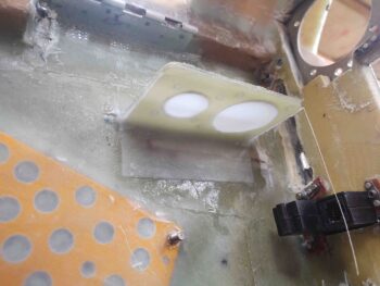
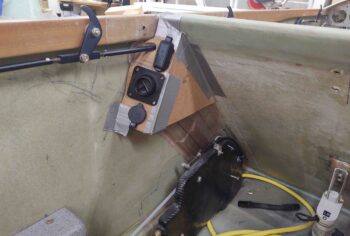
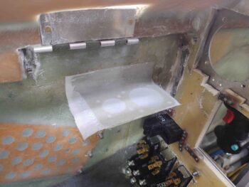
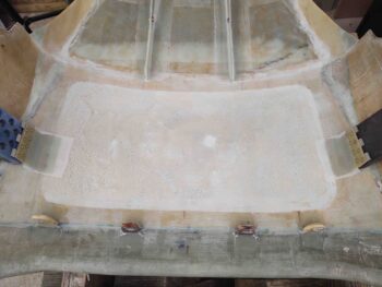
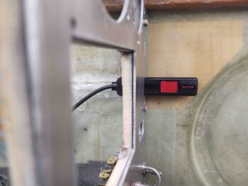
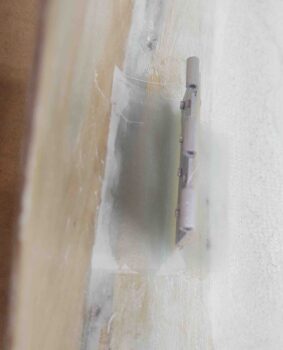
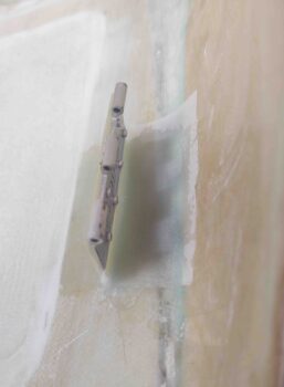
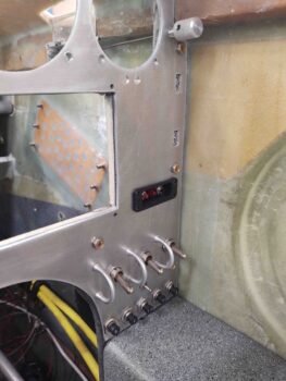
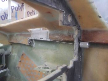
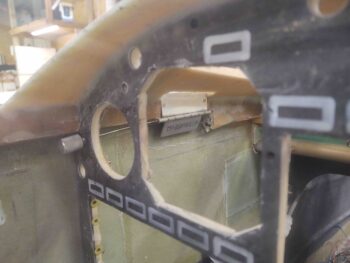
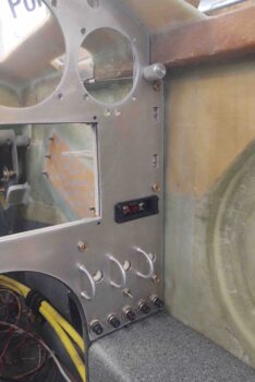
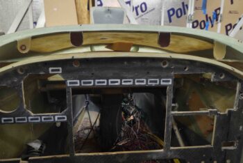
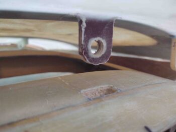
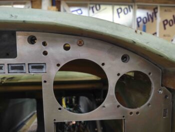
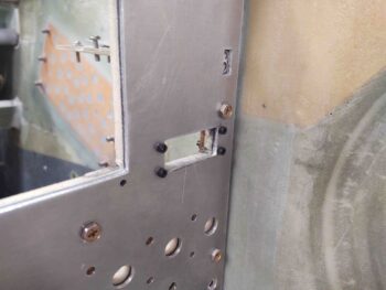
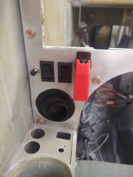
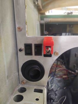
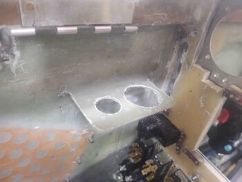
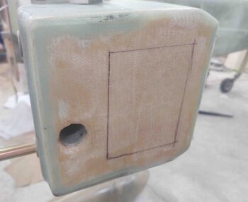
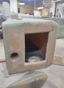
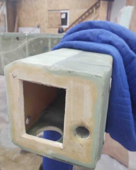
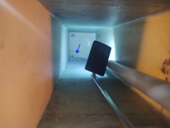
I started off today by pulling the peel ply on the repositioned/reglassed avionics bay electrical connector bracket.  I then cleaned it up a bit and did a very quick razor trim.  I still need to add another ply on the bottom, so I’ll do the final cleanup then.

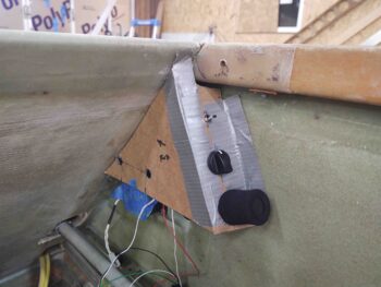
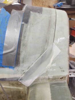
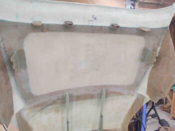
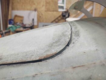
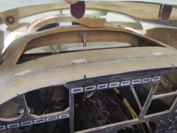
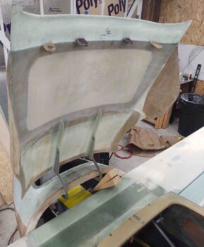
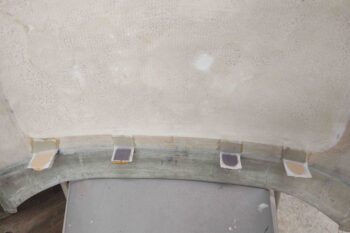
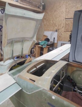
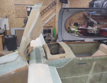
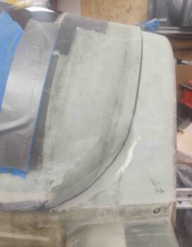
I then pulled the peel ply off the canopy left side aft lower “corner” where it interfaces with the Turtledeck.  I assessed the shape and marked a cut line to remove the excess glass.

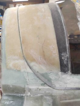
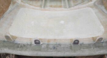
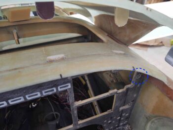
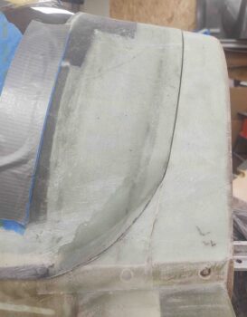
Here we have the new edge on the canopy left side aft lower “corner”…. I think it’s a vast improvement and looks much better.  And yes, I should have done this the right way prior to painting the inside of the canopy . . . some things just get missed when you’re in a hurry.

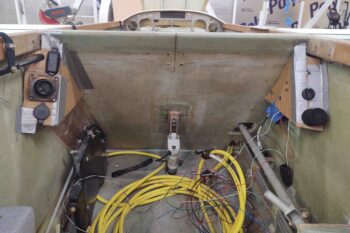
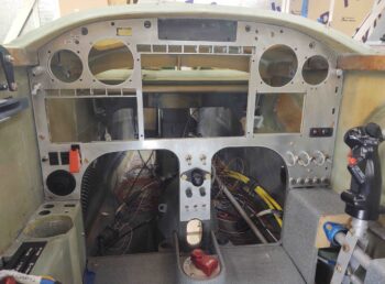
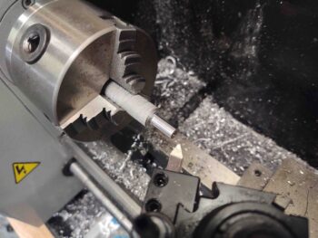
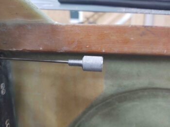
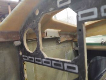
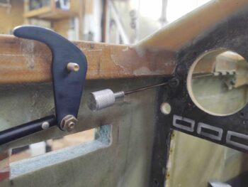
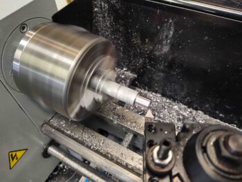
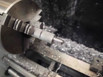
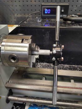
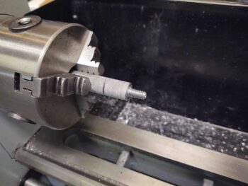
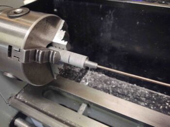
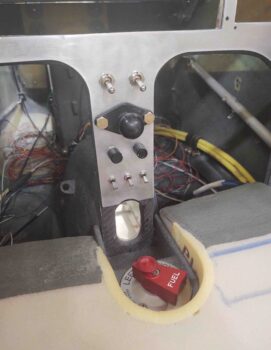
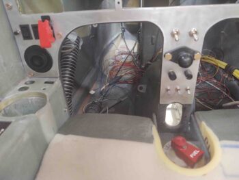
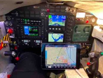
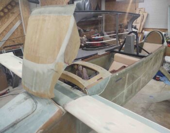
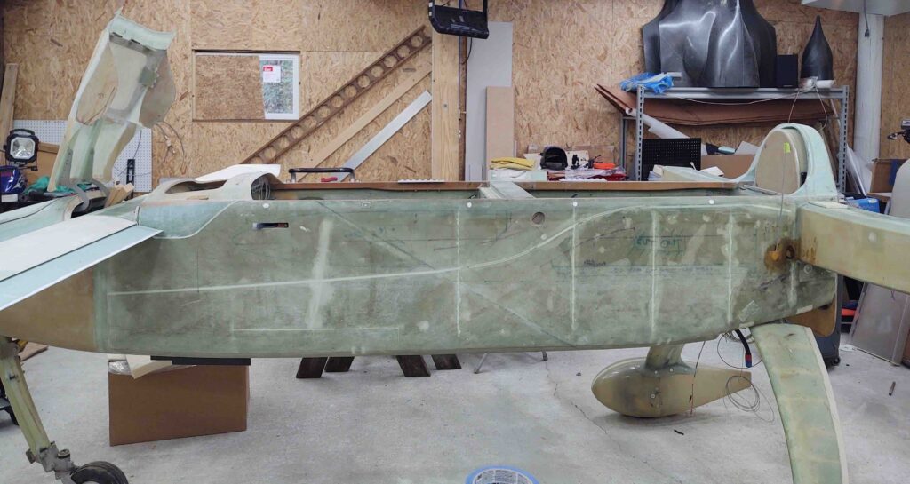
I then removed the canopy and roll bar in prep for the upcoming strake build. This is one reason I’ll need to wait a bit to dial in the canopy latch handle configuration.  The other significant reason is I want/need (for efficiency) my milling machine and lathe to be online and CNC’d to spit out much higher tolerance parts much quicker than I can do by hand.

I’ll need the wings to be on before I start measuring and dialing in all the pieces parts for the strake.  I don’t really have any help so it will be a one-man job.  To make the job of mounting the wings and removing them much easier, I am going to knock out the reversed and secured wing bolt mod that so many canardians do.

If you haven’t heard of this it is simply having the wing bolts stick out of the CS spar and then having a U-channel bracket that secures them both to the interior CS spar aft wall, and moreover keeps them from spinning.  This can be done however the owner/builder wants, with just the outboard bolts or the inboard bolts as well.  I’ll be doing all of them in this manner.  Then the wing mounting process can be a one-person affair by simply sliding the wing onto the bolts and then ratcheting the respective nuts onto each bolt.

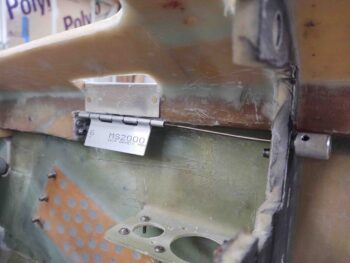
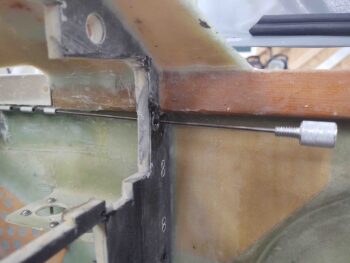
My buddy Marco just did this mod to his flying Long-EZ and had some great tips for me (I’ll cover them as I do this wing bolt mounting mod).  One of those of tips, that he researched and discussed with the Old Guard of the canard world, is cutting an access hole in the end of the CS Spar to more easily do the mod.  I may not have needed to do this if my setup wasn’t disrupted by yet another mod that I did when building the CS spar: the wire/cable tube I installed that ends on the lower aft corner of the CS Spar’s outboard face.

Why the lower aft corner?  If I go back and look at my build log it would probably say, but right now my only guess is that wire/cable tube exit location aligns with the wing wire/ cable channel.  Regardless, I can’t merely measure, cut and slide a U-channel in place since I have to work around this wire/cable tube.

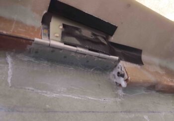
Moreover, whereas Marco used a large hole saw to create a temporary access hole to mount his wing bolts in the spar, I decided to make mine rectangular, with the sides angled somewhat like how you’d cut the top of a pumpkin if making a Jack-O-Lantern. So I marked my temporary access hatch outline.

Then cut it out and vacuumed up the mess.

Looking around at my 8-year-old work —akin to opening up yet another time capsule on this bird— I noted a big ‘ol pile of metal shavings in the front inboard corner of the spar. Clearly from when I drilled the wing bolt holes.  I of course vacuumed those out as well.

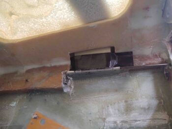
I then cut the same temporary access hole at the left end of the CS spar.

And just like the right side had another pile of metal shavings from when I cut the wing bolt holes.  Yep, these got vacuumed out as well.

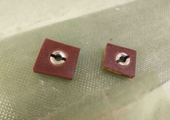
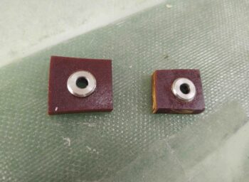
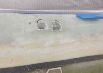
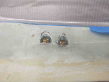
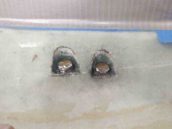
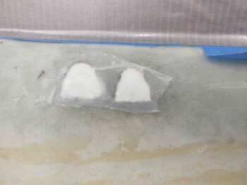
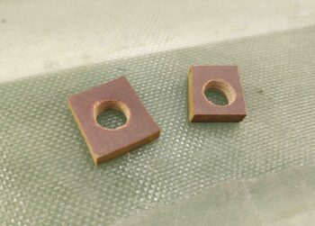
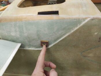
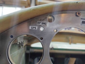
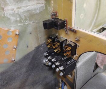
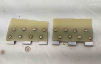
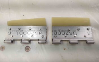
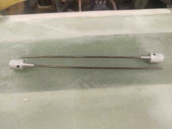
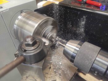
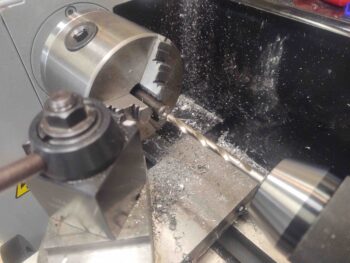
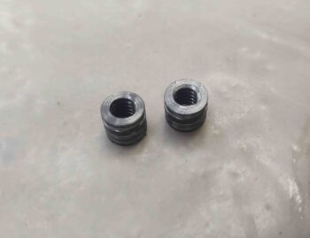
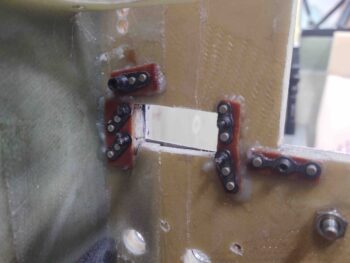
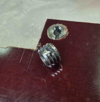
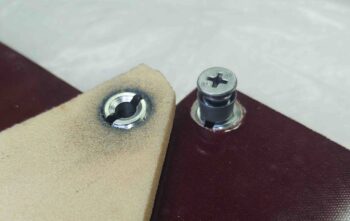
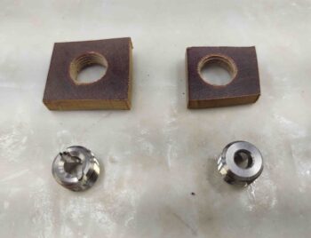
I then gathered up my phenolic plates with 1/2-20 tapped holes in them, along with the SkyBolt threaded ‘CAMLOC’ receptacles to assemble.  I was going to flox the receptacles in tonight, but I wanted to wait until I had other glassing to do since I always make up too much epoxy, even with just a gram or two, than I need when doing such a small flox job.

I understand that these phenolic pieces look a bit wonky and not symmetrical.  Part of my issue is these are 1/4″ thick, and my band saw is a small cheap one that wonders on any thick piece.  The size difference is due to the right one originally being just a test piece, but then I don’t like wasting expensive material, so I used it for this.  Once embedded into the nose sidewall, these will never see the light of day and their hideous disfigurements hidden except for the couple of pics of them in this blog.

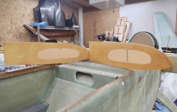
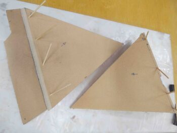
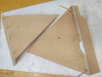
I then spent a couple of hours pulling peel ply and cleaning up the prefab Feather Light strake ribs and baffles that comes in their strake leading edge kit.  I would say on about 25% of the surfaces they had overlapping peel ply which made it kind of a pain to remove… and took a bit longer.  I would have saved 45 minutes if I didn’t have to deal with the multiple peel ply layered seams.

Still, I can’t complain that after less than 2 hours of peel ply removal I’m about 80-90% ready to start assembling/building my strakes.

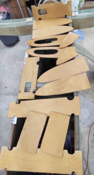
I say 80-90% because some of the edges need to be cleaned up and better aligned with the original plans measurements and shapes… nothing overly extensive though.

Also, a significant mod that I plan to do is removing more of the aft sidewall in the back seat area, just forward of the CS spar, to add more arm access (read: comfort) into the baggage compartment for the GIB. I contacted Mike Beasley since he did this exact mod to query him on fuel capacity. You see, when you do this mod you angle the BAB baffle (fuel tank inboard wall) a lot more towards the back corner of the fuel tank.  This takes away about 2.5 gallons of fuel each side.

Which leads us to mod #2.  This is often done by builders regardless if they do the “GIB elbow room mod” above.  And that is to simply use the slanted outboard OD rib –that is usually only for strake strength/rigidity– as the outboard fuel tank wall.  This pushes fuel outboard and you gain a fair bit more fuel capacity.  I know Nate Mullins did this, as a number of other builders did as well.  IIRC, Wayne Blackler advised me to do this as well.

Now the downside.  Since the spar angles aft from BL23 out to roughly BL55, putting fuel out here starts adding weight to your aft CG.  Not ideal.  Thus, as I often do, after my discussion with Mike I decided to compromise.  Since this area is a “dead cell” or a simple open air pocket anyway, I will simply split it roughly in half and only use the more forward part of this open space.  That will get me close to or slightly exceed reclaiming what would be my stock amount of fuel, while also giving me a much more comfortable back seat area, all with minimized (if any) negative affect on my aft CG.

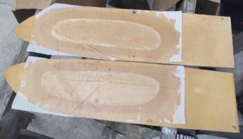
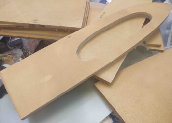
Here are the OD ribs, unfortunately with the lightening/access hole precut in them that I will fill in to configure another forward side fuel pocket.  This will also require me to cut 3 mouse holes for normal tank fuel flow in the existing RB45 outboard fuel rib.

A note on the strake build.  I’m comfortable at this point to start transitioning into the strake build although I’m not completely finished with the nose.  With glass cure cycles I can start on the strakes and fill in the cure cycle periods with working on the nose, and vice versa.


Chapter 13/18/22 – Thru-panel CAMLOCs

I got back from Greensboro early in the evening tonight and got into the shop after I unpacked my vehicle.  On the front porch was a FedEx box from SkyBolt with my “CAMLOC” studs for the thru-panel tabs to secure the aft nose/avionics cover.

I took the SkyBolt studs out to the shop and tried them out.  These are the shortest of the ones I ordered (-10) and as you can see, on the right side I probably need to drop down a size.  I’ll order a  couple of -9s and -8s when I place my next order either with SkyBolt or ACS.

Still, I’m happy with how they look, fit and function… and could certainly use all of these in the interim while waiting to replace the slightly-long stud on the right side.

I then got busy remounting the avionics bay electrical connector bracket on the interior right nose wall.  I 5-min glued it in place and then a bit later added a flox fillet and a ply of BID on top.  I then peel plied it.  Tomorrow I’ll layup another ply of BID on the bottom.

Before I remove the canopy to start on the strake build, I need to do one last thing: add a bit of meat to the aft bottom “corner” to both create a smooth curve around that “corner” and to also hide a bit of the gap with the interior drip shield.

I laid up 3 plies of scrap BID and then peel plied the BID, on both sides: underside and top.

I had meant to get a pic of the same type of addition I did a while back on the right side aft bottom canopy “corner,” but kept forgetting.  I did the same thing here with adding a small swath of 3-ply BID and then trimming it down.

Tomorrow I’ll get back to work on the nose to get it much closer to finished, and also start prepping for the strake build.


Chapter 13/18/22 – SC-1 Final Install

I started out today installing the AN3 bolts I finally ordered (and received) from Aircraft Spruce to attach the Canopy Safety Catch (SC-1).

Here are the temp screws that I used to hold the safety catch in place.

And the new AN3 bolts.  The plans call for button head screws, but those are such a pain to deal with I just went with the bolts.

Here we have the inside with the nuts securing the SC-1 bracket in place.

To get the bolts level with the canopy frame surface I had to grind them down a bit with the Dremel Tool.

I then filled in the counterbore holes with dry micro, per plans.

I then pulled the pins and popped open the aft nose/avionics cover with the cured interlocking hinge tabs working as designed.

I then took a good half hour to test out my 1/32″ flat peel-n-stick rubber seal I got from McMaster-Carr.  I checked the Gorilla duct tape and found that 2 layers of that came out to about 0.031, the same as my seal tape.  So I tacked it in place and tried it out a number of times….

Seems like the 1/32″ will do just fine.  The front hatch door still locks and opens fine.

And whatever gap it creates I can fix with an extra ply or two of glass (and then some micro) on the surrounding nose area around the nose hatch.

My last act before taking off for my weekend trip to Greensboro was to grab this pic of all the lower panel components in place.

I’ll be out of the shop for the weekend, but plan on hitting it hard when I get back Monday.


Chapter 13/22 – Interlocking hinge tabs

I started off today installing the aft nose/avionics cover interlocking hinge tabs with the pin installed, and then 5 minute glued each one to the underside of the aft nose/avionics cover.

I let it cure for quite a while before pulling off the aft nose/avionics cover and then glassing each interlocking hinge tab with 2 plies of UNI and a ply of BID.

I then got to work on cutting a notch out of the composite panel bulkhead to accept the HXr and Mini-X EFISs’ remote USB cable ports.

Here’s the top remote USB port for the GRT HXr EFIS.

And the bottom remote USB port for the GRT Mini-X EFIS.

I then drilled and tapped two 1/4″ phenolic pieces for 1/2-20 thread.  I then cut the pieces out on the band saw.

These will be inserted into notches on the internal nose sidewalls to accept the same SkyBolt/CAMLOC threaded receptacles as I used on the thru-panel CAMLOC tabs.  I assessed that at high speeds these thin side “flaps” may do exactly that: flap.  So I decided to nail them down at the corner with a CAMLOC stud.

Visually this CAMLOC will reside at the tail end of the elevator fairing.

Pressing forward, I measured the autopilot source select switch that’s currently hardwired on my panel mockup and then cut out the appropriate amount of material out of the composite panel bulkhead to mount it in the real panel.

Here’s the shot from the front (I snagged the test label out of curiosity as well).

My last task for the evening was to glass the outboard layups for the aft nose/avionics cover interlocking hinge tabs.

I then peel plied the layups and left them to cure overnight.


Chapter 13/22 – Lower right panel

I started out the day once again pulling peel ply and cleaning up the layups on the aft nose/avionics cover thru-panel CAMLOC hinge tabs, only this time on the forward (nose) side of each tab.

I then configured and designed the G10 tabs for the aft nose/avionics cover interlocking hinge latches.  I was in a rush since my friend needed someone to watch her daughter for most of the day as she went to an appointment, so round 1 of the hinge tabs, when I assessed them later, in position at my desired mounting point on the inside surface of the aft nose/avionics cover, were too short to comfortably fit the 2 rows of rivets I planned on using to secure the G10 pieces to the aluminum hinge sections.

Of course I discovered all this much later in the evening (the second and final versions are at the end of this post).

Once my little shadow had left early evening, I took a break for a bit before heading into the shop.

Back in the shop I wanted to spend a good hour or so before it got too late to use the very loud Fein saw to finish making the pockets on the back side of the panel (technically forward/nose side. . .) for the big 3 lower right panel switches.

Here’s a shot of the lower right panel after removing material from the original composite panel bulkhead for the switches to fit properly and deep enough.

Note in the upper left corner you can see where i also cut out the sidewall bracket that secured a couple of electrical connectors.  That will be moved up slightly and forward a hair.

I also cut out material in the original panel to mount the alternate static source switch on the upper left side of the panel.

With the lower left, middle strut, and lower right panel components mounted, I’m now moving into the middle area of the panel, which only has a few components: the aforementioned (complete) alternate static source switch and the 2 EFIS remote USB panel ports on the middle right edge of the panel, just below the longeron.  I’ll try to knock those out tomorrow.

After I made the major noise with the Fein saw, I got busy redesigning the next version of the G10 tabs for the aft nose/avionics cover interlocking hinge latches.  On these new versions I really only added about a 1/4″ along the bottom edge next to the actual hinge tabs to –again– ensure enough area to have 2 row of rivets.

So here we have the final versions of the interlocking hinge tabs that will be installed. It’s late now so I am kicking this task off until tomorrow.

The install process will be to 5-min glue these to the underside of the aft nose/avionics cover when it is in the down position, with the hinge pins installed.  One reason I needed taller G10 tab sections is that I wanted to push the attach points to the inboard on the aft nose/avionics cover.  This will align these tabs more center in the thru-holes in the aft nose substructure, and also provide more clearance with the protruding rivets since I wanted to mount them head side on the G10 for a more secure grip.

Tomorrow I’ll try to knock out the install of these hinge tabs by getting them glassed to the cover.

Chapter 13/22 – Aft nose hinge tabs

I started off in the shop today glassing the aft side of each aft nose/avionics cover tab with 1 ply of BID.  I then peel plied the layups.

I then got busy on the lathe machining the knobs that secure the wire pins for each interlocking hinge assembly which is another added securing point for the nose cover.

I made up the first knob to ensure it would work, and as you can see here it does.  The wire pin does have to contort just a bit, but not bad enough to stop this from working (as I can tell so far).

When the hinge pin is out to raise the aft nose/avionics cover, it will have a hard stop (which I plan to work on tomorrow) that keeps the pin in the last segment of the nose (longeron) side of the hinge.

Here’s a clear picture of the knob that attaches to the hinge pin via a set screw.

I then tried the same initial knob/pin assembly on the left side, which worked out just as well.

I then tested it with the forward CL-2 canopy latch hook to ensure there was clearance when the hinge pin was all the way out (aft), and as you can see there is.

With the first hinge pin knob looking good, I started in on knob #2.

This is the first time I’ve knurled something, and since I tried to do it for both knobs altogether, it flexed the aluminum rod a bit and didn’t quite get the bite I was hoping for.  But it still turned out acceptable, so I pressed on.

Here I’ve added some pics showing how I used a die to cut the 1/4-20 threads.

I then tested the drilled center hole to see how the wire pin fit… nice and snug.

Here are the left and right knob/hinge pin assemblies for the aft nose/avionics cover.

Here is the right knob/pin assembly installed.

And the left.

By this point in the evening, the BID on the aft faces of the CAMLOC hinge tabs was cured, so I trimmed and cleaned them up before glassing the forward tab faces with 1 ply of BID.

I then spent a good 45 minutes working on the lower right panel.  It was getting a bit late, and using the Fein saw makes a LOT of noise, so after I got the circuit breakers and tach source select switch installed I called it a night.  Over the next day or two I’ll finish up the 3 big switches (Master, Ignition 1 and Ignition 2) that will get mounted down in this corner.

And with that, I called it a night.


Chapter 13 – Aft nose cover tabs

I started out today pulling the peel ply and cleaning up the layups on the forward side of the aft nose/avionics cover thru-panel CAMLOC tabs.  I then laid up 2 plies of UNI on the aft side of the tabs overlapping about an inch onto the underside of the cover.  I peel plied it and left it to cure for a couple of hours (before mounting it back in place on the nose, to ensure the tabs cured in the correct position).  Sorry, no pic of this.

After an hour or so assessing my interlocking hinge securing points for the aft nose/ avionics cover –located on each longeron just forward of the paneI– I then got busy making up some steel 1/4-20 threaded hardpoints to secure the interlocking hinges’ pin knob, which will be on the face of the panel in each upper corner.

When I want to open the aft nose/avionics cover, part of the process will be to unthread these knobs, about the size of dimmer switch knob, and slide the pins out of the interlocking hinge pins along the longeron.  Another securing point/release for the aft nose/avionics cover.  To remount the cover I’ll simply reverse the process: insert the interlocking hinge pins and thread the knob in the secure/closed position.

I was leaning towards using a 10-32 nutplate or RivNut to thread the knob into, but after assessing the hinge pin diameter I needed a bigger threaded screw-post that will both secure the hinge pin in place and the attach to the knob (used to insert/remove the hinge pin).  It will become more clear over the next day or so… and as I said on the nose hatch video: I plan on making another one for the aft nose/avionics cover.

Here are the 2 steel 1/4-20 threaded panel inserts.  I lathed 3 flox grooves around the outer surface for better gripping in the 3/8″ holes I drilled into the panel.  I then floxed these guys into place…

Back to the aft nose cover thru-panel CAMLOC tabs… here they are all glassed up with a quick trim.

And here’s a shot of them with the slots on the top surface of the aft nose sub-structure that allows the tabs to fall right into place behind the panel [the right pic also has a shot of the right side steel threaded panel insert floxed into place (blue dashed circle)]

I took this shot of the panel to show the 4 associated CAMLOC thru-holes on the panel for each tab (blue arrows).

Another shot of the tabs with the cover open, for a bit of overall size perspective.

Here we have tab #3 after I drilled it out and tapped it with 1/2-13 threads… the threads are actually visible in this pic.

I then threaded a SkyBolt (CAMLOC) receptacle into each tab.  After some thought yesterday I decided to also flox these in place as well… so each receptacle was slathered in flox before threaded into place.  I then spent a few minutes on each one to ensure no flox was where it shouldn’t be.

After the tabs were all cleaned up, about a half hour later, I closed the lid and grabbed a shot of the threaded SkyBolt/CAMLOC receptacles peeking though their respective holes in the panel.

With that, I left the floxed homemade threaded inserts and the threaded/floxed SkyBolt receptacles to all cure overnight.


Chapter 13/22 – One tab at a time

I started out first thing in the shop today floxing in the phenolic nutplate assemblies that will secure the ELT remote head to the instrument panel.  Since the ELT remote head housing is plastic, and I like to have the nutplates set in flox nice and tight, I removed the ELT remote head so it wouldn’t get damaged.

Here are the ELT remote head 4-40 nutplates floxed in place on the back side of the panel.

I’ll remind you all that I’ll have 4 CAMLOCs across the top of the instrument panel that will lock into 4 tabs to secure the aft nose/avioncis cover into place.  I had originally planned on simply floxing the SkyBolt threaded inserts into the tabs, but upon closer inspection I realized they have grooves commingled in the threads where the posts of the 1/4-turn studs lock into.  Clearly I don’t want these full of flox.

I checked to see if I had a 1/2-20 tap on hand, which I did, so I tested out tapping a hole in some 1/4″ thick phenolic I had on hand.  It held perfectly.

But phenolic is a bit heavy, even though these tabs aren’t that big.  I had planned on using the very dense H250 foam, so out of curiosity I drilled and tapped it 1/2-20 as well.  To my surprise it held the threads cut into it and securely held the threaded SkyBolt/CAMLOC insert.

I decided to make the center 2 panel CAMLOC tabs out of phenolic, and the outer tabs out of the lighter H250.

Here are the 2 phenolic center tabs.  I forgot to grab a pic of the 2 outer H250 foam tabs.

I then finalized the location of the tab through-holes on the top of the aft nose frame, just forward and bordering the original panel bulkhead.  I then marked the holes for cutting.

I drilled a 3/8″ hole into each of end of the marked tab through-holes.

And then finished cutting out the CAMLOC tab holes with the Fein saw.  I then taped the holes up with duct tape in prep of 5-minute gluing the tabs to the aft nose/avionics cover.

A little bit later, after I 5 minute glued the panel CAMLOC tabs to the underside of the aft nose/avioncis cover, I glassed the forward side of each tab with 2 plies of UNI.  I then peel plied the layups.

I let the tab layups cure for a good couple of hours while I got to work on cutting, drilling and Dremeling out the switch and dimmer mounting positions on the back side of the panel center strut.

Here’s the result.  I’m really pleased with how the components look installed.

Another shot, including the lower left part of the panel with the switches I installed last night.

After the panel CAMLOC tabs’ glass cured a bit on the aft nose/avionics cover, I then remounted the cover back on its hinges and weighted/taped it down.  I want the tabs to cure inside the through-holes to ensure they are in the correct position.

I was going to glass the other (aft) side of the tabs tonight, but considering what a pain they’re being with aligning in the through-holes, I want a full cure on them before I glass the opposite side.

The layup schedule BTW is 2 plies of UNI each side of the tabs. Once cured, then I’ll drill a hole and tap 1/2-20 before installing the threaded SkyBolt/CAMLOC insert.  Once the insert is in place I’ll glass each side of each tab with a final 1 ply BID that will overlap onto the threaded insert, both front and back.


Chapter 13/22 – Surprise visit!

I started out this morning compiling a much needed and much overdue order for Aircraft Spruce.  I did an inventory of my EZ-Poxy resin for the upcoming strake build and discovered I only had about half a gallon left from my GIB thigh support fuel sump build. So I pulled the trigger on another gallon just to be on the safe side.  I also bought a few more SkyBolt (CAMLOC) receptacles for securing the aft nose/avionics cover and the AN3 bolts to secure the canopy safety catch (SC-1 . . . finally!).

Lastly, in order to get the cockpit area prepped for paint I need to have on hand and install the ELT antenna (most likely right behind the pilot’s seat), so I figured it was time to order the ACK E-04 ELT and get those components here for final assessment, configuration and install.

Upon coming back in the house with all the data I gained during my workshop recon I noted that I had a missed call from Marco.  By the time I called him back he was at his airport on high alert ready to launch on a high priority sortee to . . . ?  Here!  Wow… ok. (He called the other day and said he was looking to hop down here for a short visit when the WX was good… and today was a beautiful Fall day).

While he was getting airborne I ran out to the shop and threw all the avionics and instruments into the panel, including the GNS-480 GPS.

I had also started my initial cleanup on the aft nose/avionics cover hinge tabs, so I finished those up post haste and put the cover back on the nose.

BTW, here’s Marco’s recently updated and quite awesome new panel in his flying EZ, JT:

When I picked Marco up from the airport, we took the requisite selfie for Terry Lamp! (grin)

At the workshop, Marco started his inspecti … uh, tour.  Here he is telling me everything I could ever want to know about MY milling machine (hehe).

We then checked out the build.  He tested out the front seat and then while he was in the back I climbed in for another selfie.  It really was great to have him down here… it’s been over a couple years now since he’s seen the build.

Overcome with awe and sheer respect for the quality of my build (haha) Marco was rendered speechless, and could only offer up his respects with an inspiring, perfectly executed salute!

Marco snapped this shot from the back seat looking forward.

After I dropped Marco off back at the airport and he departed (amid a buzz of onlookers talking about ‘that’ odd airplane . . . ) I returned to the shop and got back to work on the aft nose/avionics cover.  I was FINALLY able to dial in the hinge configuration and get those suckers mounted.  Here we have the aft nose/avionics cover in its MG-inspired open position.

Another shot of the aft nose/avionics cover in the open position.

And one last shot . . .

As I work on the aft nose/avionics cover I plan on spending a good hour each day knocking out a section of the panel to get it so the components are all installed and I can prime, paint, label and clear this sucker.

Since the heavy lifting is complete with the install of the main avionics, I’ve mentally broken down the sections to be completed as follows: the lower left corner, followed by the center strut, the lower right corner, the mid-section, the upper section, and then all the Korey lights: GNS-480 annunciators and panel ON/OFF indicators.

Thus, today was the first to be completed of all those sections: the lower left corner.  Here we have the eyeball air vent installed, the outboard oil cooler switches installed, the RAM air open/closed rocker switch installed, and the red flip covered fuel pump switch installed. To be clear, installing these switches meant clearing out a good bit of material on the back (nose) side of the original composite panel bulkhead.

Another shot of the fuel pump switch in the ON position.

My last task of the evening was slightly increasing the size of the opening on both the aluminum and composite panels to accommodate the ELT remote head to be mounted externally on the face of aluminum panel.  I drilled the four 4-40 holes through both panel structures, and tomorrow I’ll flox in the phenolic nutplate assemblies to secure the screws.

With the aft nose/avionics cover hinges installed I expect the pace of the remainder of the cover install to accelerate a bit.  I will still be concurrently installing the panel components, but over the next week I expect both to be complete as I transition into the strake build (with a few other build tasks sprinkled in as well).