Chapter 23/25 – Cowl glass required

Today was about knocking out some glasswork for upcoming tasks as well as remounting the lower cowling and assessing clearances with the engine now back in its original position.

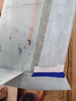
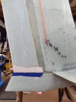
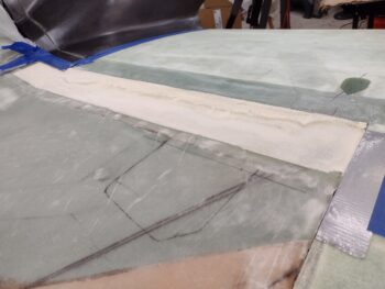
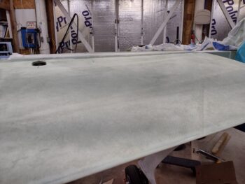
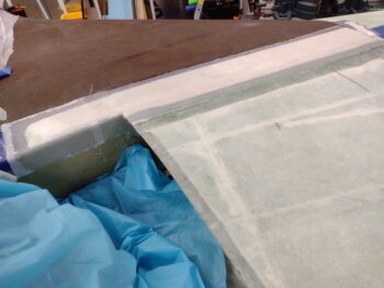
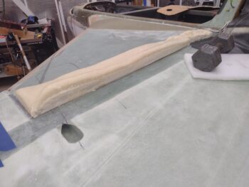
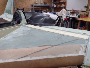
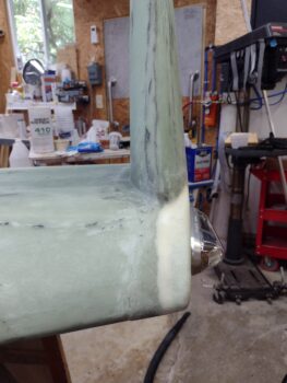
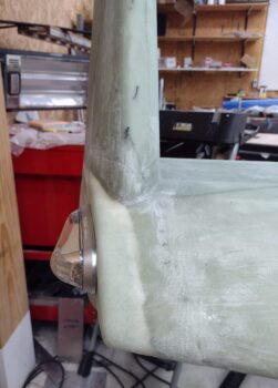
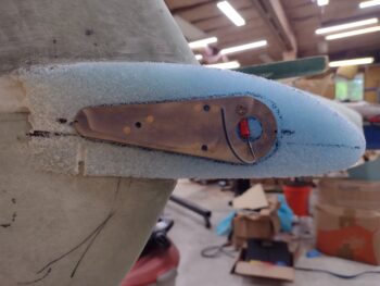
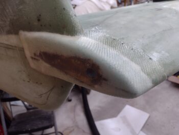
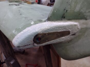
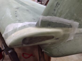
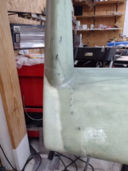
Starting off, the outboard edges of my strakes tend to dip down right in the last 0.5″ inch around the perimeter of the strake edge.  This dip of course causes there to be a more pronounced uneven skin height level between the wing and the strake.

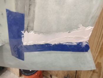
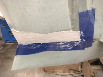
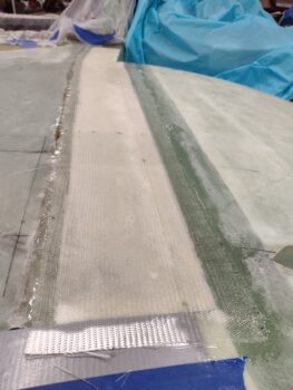
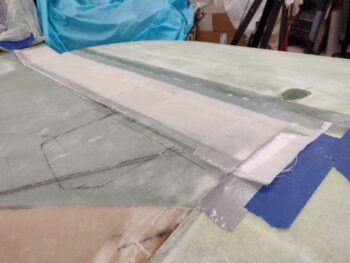
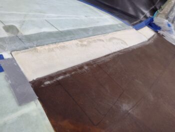
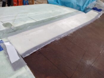
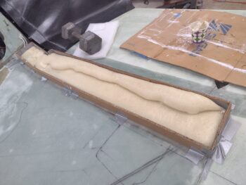
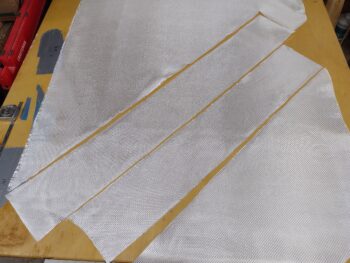
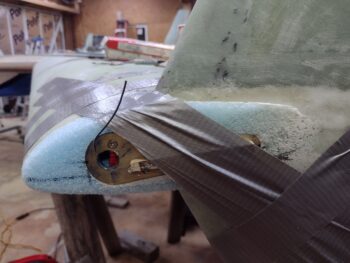
Instead of just slathering on a bunch of micro, flocro or flox, I wanted to both stiffen this edge up a bit while giving it some increased height to better match the wing.  On the end of both strakes I determined different thicknesses of BID that I was going to add, ranging from 1 to 5 plies.  3 plies was the most common addition, while I only needed 5 plies in one spot on each side, both about 3/4″ in length.

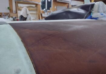
The width of the added BID started out as 0.4″… clearly it varied a slight bit as I manipulated the layup around the leading edge.  After prepregging the BID and getting it laid up, I then peel plied the layups.

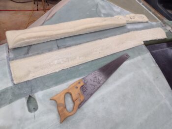
A few hours later I pulled the peel ply and cleaned up the layups.  I may add another ply or two to the still considerably depressed spots, but the majority of the areas I’m calling good and feel comfortable with still a decent application of micro on the edge now.

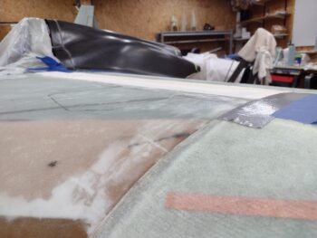
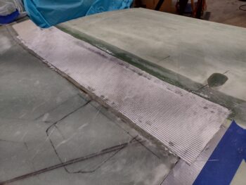
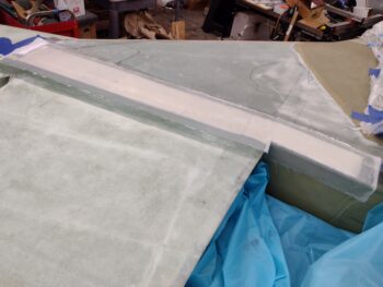
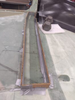
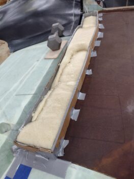
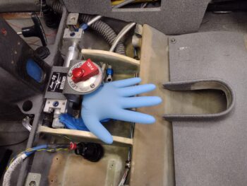
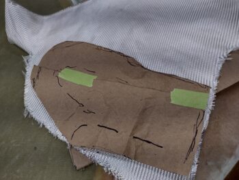
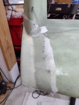
Another glassing task that I have on my list that needed to be done before I consider this bird operational is a reinforcement layup on the pilot right armrest.
[I have just under 20 layup jobs that I’ve identified that need to be done (each task may require multiple layups).  About 75% of those must be done before the airplane goes airborne, others are mods such as baggage pods, wing LE landing lights, HUD mount bracket, etc.]

The plans call for 2 plies of BID, but I only used one.  Now I’m reinforcing the center area where I will push down when extracting my less-than-Twiggy self and getting into this bird.

Plus it was a fairly quick kill and I was trying to get out the door to meet Jess for a late dinner.  Not surprisingly, all the glass & CF I used were scrap pieces.

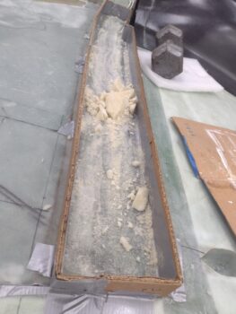
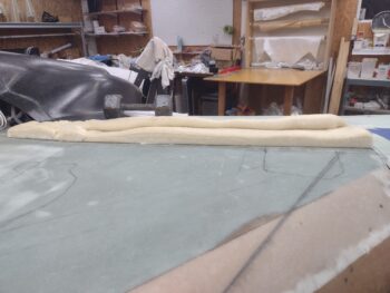
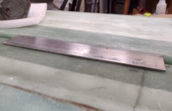
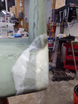
Here’s both sides of my Lantor Soric test piece that I laid up 1 ply of BID on each side.  One side was peel plied, the other not.  Yes, there’s air gaps around the perimeter where having a micro (or flox) transition would be good of course.

With a ply of BID on each side the thickness came out to almost 1/8″.  Also, as you can see on my well used scale (it means I’m building a lot! … ha) my ~2″ x 2″ test piece is a whopping 8 grams.

If you’re wondering why I’m interested in this Lantor Soric stuff, it’s because it will be the material that I most likely construct my wing/aileron fences out of… so far so good!

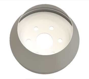
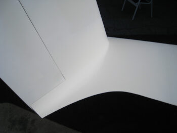
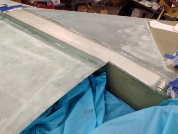
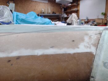
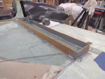
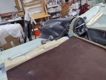
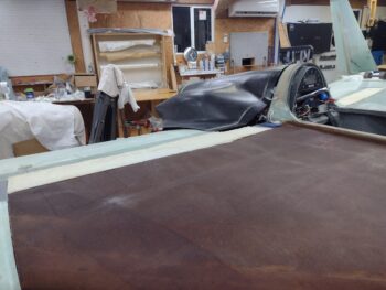
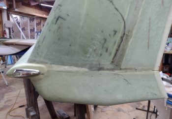
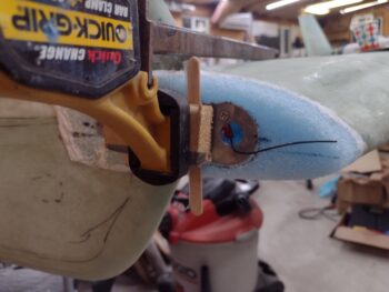
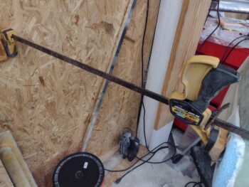
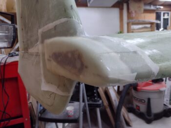
After returning home from dinner, I tucked away all the dangly stuff on the engine to allow me to mount the bottom cowling to assess clearances.

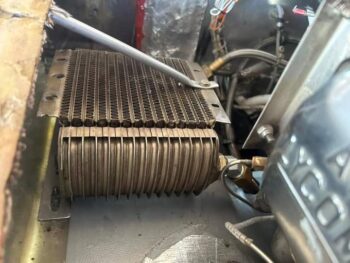
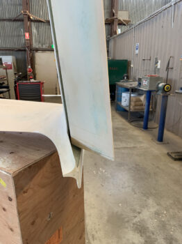
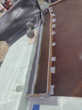
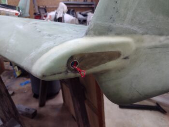
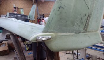
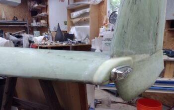
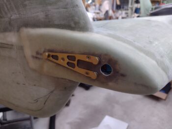
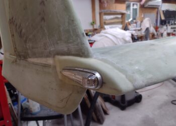
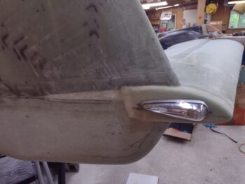
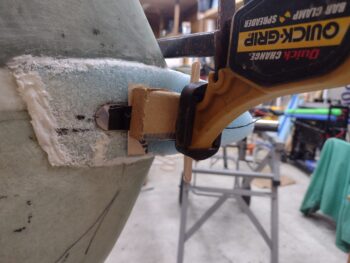
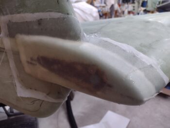
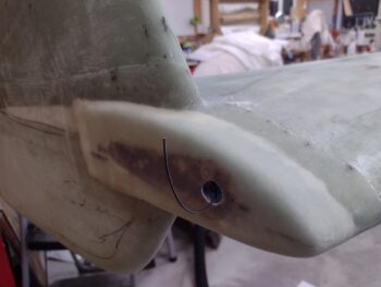
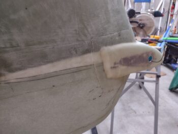
Yes, the gap between the spinner flow guide and the lower cowling is much tighter now, at just over 0.45″ … but I can manage that with no serious effort.  The big issue is the inboard left exhaust pipe, which the bottom of the 90° bend is now touching the cowling.  Moreover, my carbon fiber induction tube is just a hair away from the cowling as well… although not touching!

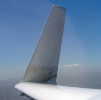
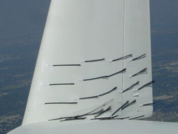
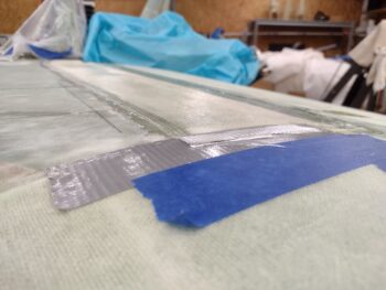
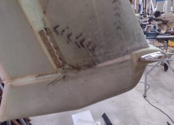
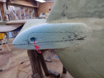
If you look closely you can see black Sharpie marks all over the bottom cowling.  I spent a good 45 minutes assessing my next steps, and yes… I will be recontouring major portions of the aft, mid to upper areas of the bottom cowling.  In addition, I will be extending the tail end transition of the RAM air scoop all the way to about 10″ in front of the boat tail “rudder” fin.  This is the only way I can see to add in some clearance to the air induction tube on the bottom of the cowling without a total rebuild.

More to follow of course, and I plan on getting started soon.  But we’re having another major heat spell… I went to have a glass of red and ponder my bottom cowling fix actions on the front porch at 11pm tonight and it was over 90°. . . clearly just too darn hot.  My point is that I will not be doing a lot of sanding on the bottom cowling during super hot days, so it may be a few days before I get a somewhat cooler day to knock that out.

Chapter 23/24 – Energy & Angles

I learned from my Air Force fighter pilot uncle that dogfights are all about energy and angles.  Pretty sure that’s one of the principle themes of what is taught at Top Gun and other Fighter Weapons Schools.

Well, I’m clearly in a dogfight as well in getting this bird built… and just as the U.S. military did with Top Gun, I needed to refocus on energy and angles a bit in regards to my energy producing device, aka engine.

But first… I started out first thing this morning to get some glass curing.  I had planned on knocking out 3 sets of layups before throwing myself headlong into the upper cowling install.

I got this one set below knocked out before I started messing with the engine angle. Here we have the BID going onto the top side of the left winglet intersection fairing made up of carbon fiber on wood.

And here the initial top side layups are complete and peel plied on the left winglet intersection fairing.

And I I then did the same on the right side.

When I mounted the 3D printed mockup mod of the prop spinner flow guide and subsequent addition of the spinner, I wasn’t focused on the ANGLE of the aft blue face of the flow guide.  I texted some pics to my canardian buddies and in one reply, Marco stated that it may just be an optical illusion but that my spinner looked a little pointed upwards going aft.  I thought he was just being a bit snarky and passed it off with a snarky comment back.  Case of the snarky comment closed… or so I thought.

Clearly the vinyl record sized flat disc that now occupies the very aft of the airplane (with the spinner off) provides a much larger visual reference plane to observe than just that of the more diminutive prop extension mounting flange.

And then I saw “it.”

As I was heading back into the house I circled wide around the left winglet and paused to look at the top cowling.  Once I saw the angle of the bright blue disc on the aft side of the bird I could then clearly not “unsee” it.  It was glaring that my prop angle was off… notably.  I now understood what I initially thought as just a punky comment from Marco was actually a very spot-on observation of a detail that I had hugely missed.

Here’s a closer look at the prop angle.  I messed around with a 2×4 and other material to assess this forward leaning prop.

I knew that with a lot of weight in the nose and having not attended to the tire air pressures in months, that the nose was probably a little low… plus I know the shop floor angles down towards the front doors.

I checked the longeron angles and they confirmed the nose was in fact low. I put a 5/16″ piece of wood under the front tire and also filled it with air.  My longerons are always a hair of a degree off from each other, and at this point the left showed 0.1° degree down and the right flashed between 0.2° and 0.3° down… for this exercise I called it 0.2° down and averaged the total at 0.15° nose down (all this actually preceded the prop angle pics above).

I dug back into the plans to confirm that my engine mount was attached in the proper configuration.  I measured the top aft edge of the mounting cup on each side, from the firewall and also the bottom engine mount cup as well.  The F.S. reference point in the plans is from the front face of the firewall, which is F.S. 125.  The most important data point here is the difference between the top and bottom W.L.’s of the engine mount as spelled out in the plans: a 0.25″ delta.

My measurements, as shown here are about as spot as can be measured: 0.25″ difference on the left, 0.26″ difference on the right.

I took the bottom cowling off and spent a good hour rigging up the engine hoist, and removing the shims off the bottom engine mounts.

With the bottom engine mount bolts only finger tight, I rechecked the angle of the engine at the prop extension hub.  Interestingly, with a 250’ish pound engine —after removing 0.1+” shims— the angle only dropped from 1.5° to 1.2°.  That told me that engine weight alone was not compressing the Lord mounts to any real amount, which is what I somewhat expected.

After tightening the bottom engine mount bolts to spec —sans shims— I was now looking at only a 0.6° angle on the prop extension face.  But don’t forget the nose is about 0.15° low… so the actual angle is between 0.5° to  0.45°.

In researching engine mount shims and in also talking with the Lord Mount folks, it’s not surprising that engines tend to to drop a bit after the mounts get “exercised” and the engine settles into place after its operated.

Again, a closer shot.  At 0.5° aft engine up —clearly less than a degree— it’s close to the center mass target and the tendency in the future is for it to settle.  Better this scenario by far than that of the engine angle being too low.

Out of curiosity, I set the level with the water bubble just touching the aft line and measured the gap at the top between level and prop stud: 0.05″ engine drop until within the minimum “level range.”

With the bubble centered that gap is 0.079″… so at a hair over 1/16″ the engine will be exactly level.  Considering I need to still mount the prop, crush plate, prop bolts, Belleville washers, spinner and flow guide, not to mention the engine baffling, and that the engine hasn’t been run to settle into the mounts, I’m simply not going to worry about this angle from here on out.

What I do have to worry about is component clearance with the lower cowling. I will state emphatically that it is time to put this engine vs cowling clearance issue to a stop. If I need to start hacking up and reshaping the bottom cowling I will proceed to do so.

After the latest rounds of engine shenanigans, multiple hours later, I finally got around to pulling the peel ply and tape off the winglet intersection fairings.  I had planned on laying up a single ply of BID along the fairing’s underside, both along the wing TE to fairing seam and also along the winglet to fairing corner seam as well… but it was late and I wanted a break from the engine angle drama.

I will note that I weighed the trimmed carbon fiber/wood fairing structures together at 1.34 oz.  I then added the glass weight and doubled that to estimate the epoxy weight as well.  Currently the added weight is around 3.4 oz.  I expect with foam, micro and glass that the estimated total added weight of these fairings will be about a pound.

Once I add and shape pour foam on the top to blend the winglet intersection fairing into both the wing and winglet, with a pleasing shape radius, I’ll most likely significantly trim down the height of the mini wall that will create the outboard upright of the fairing, against the bottom inboard rudder.

And with yet another long (and dramatic) build day under my belt… yup, calling it a night!

Chapter 19/20/23 – Spinner mockup

Thankfully I was greeted this morning with Max still whirring away printing out the prop spinner flow guide mod test mockup.  It would still take nearly 2 more hours to finish up the print, which is when I grabbed this pic here.

I then set it next to my current flow guide to show the stark contrast between the shape and size between them.

Another couple shots of the current flow guide and the test mod mockup.

Entering the shop I immediately chased out 2 squirrels that think the workshop is their residence.  I then saw this massive spider on the wall… at least 2.5″ inches across the legs.  I yelled at him for letting those damn squirrels into the shop!  If you’re gonna hang around ya gotta do some work!

I then installed the test mod mockup for the prop spinner flow guide.  It was a tight fit, but it went right on.

Here’s the clearance between proposed prop spinner mod configuration and the lower cowling… it makes me think that I may just very well add a very slight curve to the flow guide.  I’ll assess and see.

Another couple shots at the side of the flow guide mod.  I’m thinking I may add to the flow guide a bit by simply taking the front edge straight forward with a 1″ lip… with a nice radius flaring out to the aft expanding flow guide.

I then mounted the prop spinner.  Although my measurement on my 3D printed flow guide is correct, I think that the nearly 1″ wide mounting flange on the flow guide for the spinner is not a straight cylinder as I printed it out, but actually expands out a hair as it goes forward.

The spinner was a hair bit wider in diameter than the flow guide and I needed to put some duct tape internally to make it a snugger fit.  I then set the top cowling in place.

Of course this still provides a good idea as to how the spinner will look installed. Remember, the top cowling and exhaust pipes have yet to be trimmed to final configuration.

After a bit of staring down the prop spinner and pondering various aspects of its upcoming installation, I then got to work on the winglet intersection fairings.

I’ll note between last night and today I did a fair bit of research (RE-research actually) and observed that various builders had used a 2-ply BID layup as the foundation for their fairings.  I decided to use very light wood pieces cut nearly to the exact shape I wanted and then add carbon fiber for stiffness and rigidity.

The trailing edge of my left wing is a hair thicker than the one on my right wing, so I used 1/16″ Balsa wood (which I just bought) for the substrate on the left and some on-hand 1/32″ Birch plywood for the substrate on the left.  The difference of thicknesses in these areas will be flushed out with pour foam and subsequent micro finishing.

After cutting the actual left and right wood substrate pieces, using the cardboard template I made up the other night, I then cut some carbon fiber and peel ply for each one as well.

I then laid up the carbon fiber on the wood substrates and peel plied the layups.

I’ll point out that the carbon fiber is only going on these pieces and will not be securing any component to any other component… thus with these in place between the wing and winglet, and secured with E-glass fiberglass, any twisting, flexing or bending moments will be primarily at the joints secured by the fiberglass—and not specific to these carbon fiber reinforced wood pieces.

Since these were fairly small layups I used fast hardener, and had enough epoxy left over in my cup that I didn’t want to waste it.  I quickly unboxed my roll of Lantor Soric and cut approximately a square inch off of it.

I then wet out a scrap piece of BID, slathered up both sides of the Lantor Soric piece before covering it with another ply of scrap BID.  I had to hurry because my epoxy was starting to cure in the cup and was turning the consistency of thick honey.

After the carbon fiber and peel ply was in place, I then covered each of the fairing pieces with Saran wrap before piling on some sheets of steel and weights to compress the carbon fiber/wood substrate assemblies and keep them nice and flat (note my trimmed Lantor Soric test piece).

A couple of hours later I removed all the sheets of steel, the Saran wrap and the peel ply.  I then left the carbon fibered covered wood winglet intersection fairings to cure overnight.

And called it a night!

Chapter 23 – Spinner flow guide mod

I figure if I’m going to discuss modifying the spinner flow guide that ya’ll might want a reminder of what the current one looks like.  I’m sure you’ve seen this “lampshade” style flow guide before since it’s probably the most common, or close to it, for the ‘Hershey Kiss’ style spinner.

Here’s an inside shot as well.  This flow guide is designed to mount to the prop flange on the prop extension side and then butt up against the aft side of the flywheel on the forward side.

Again, in its current stock state this “lampshade” style flow guide will not fit into the aft opening of my cowlings.  To use the Catto prop spinner I need to modify the flow guide shape to be more along the line of the style Klaus Savier sells on his Lightspeed Engineering website:

Although it’s not overly visible, notice that the flow guide above does not butt up against the aft face of the flywheel, but rather curves around and free floats over the prop extension.  In order to install the flow guide it clearly has to fit around the prop extension prop flange, which is normally 7″ in diameter.

I plan to reuse the aluminum mounting plate, mounting flange and nut plates from the current flow guide, and remove all but the aft 1.3″ of it.  Moreover, in my design modification I need to ensure that its configuration avoids the cowlings’ aft opening edges, thus the resulting design on mine is not curved like the one above, but rather straighter.

After getting the bolt patterns dialed in and test-fitted, I then modeled up the rest of the modified prop spinner flow guide in Fusion 360 CAD:

Here’s another shot of the aft face of the flow guide with the mounting flange for the spinner and the bolt stud holes.

Finally, a look at the inside of the new, modified prop spinner flow guide.

As I discussed yesterday, since “Geeks gonna geek!” for no real damn good reason, I spent a good 2-1/2 hours recoding and re-tweaking my firmware settings because somewhere there is a momma’s-boy that apparently needs to have a sense of purpose in life by arbitrarily changing crap!!

But I finally got it.  One more round of this BS and I’ll be changing my firmware from the 3D printing world’s darling, Klipper, back to something stable and boring like Marlin.

Here’s the initial part of the print: the aft face of the flow guide.  I started with blue ABS but didn’t want to burn through the entire roll of it.

Although I made the mounting face only 0.05″ thick, for something this big around it took a good bit to lay down that much plastic.  If you look closely at the screen below you can see at this point this thing had already been printing for 5 hours and 11 minutes, with another estimated 12-1/2 hours to go.  And that’s at a speed nearly twice as fast as my other 3D printers!

About an hour after I grabbed this shot I swapped the filament out to a fresh new roll of silver ABS to ensure that the print didn’t run out of plastic in the middle of the night.  Plus I didn’t want to use all my blue ABS in this one print.

A bit later in the evening I sanded the micro I had applied to the bottom inboard edges of the rudders.  I also removed all the protective tape and cleaned up the surrounding glass.

Yes, definitely not good enough for the actual finish of the rudders, but good enough for what I’m doing here: just getting a decent straight fill for the tape to sit straight on….

I then taped up the bottom of the rudders and cut the associated peel ply for the upcoming layups for the winglet intersection fairing, which I had planned on doing tonight.

But I hadn’t sat down and really thought through my layup schedule from A-Z, and it was starting to get a bit later in the evening.  Jess had just arrived, being sweet to come over and cook dinner, so I decided to kick this layup can down the road until tomorrow.

After a great meal with Jess, and then switching the filament over to the silver roll… and with all looking good with Max (my new 3D printer), I called it a night.

Chapter 23 – Workin’ prop spinner

As I prepare to mount the upper cowling I want to know if & how my Catto prop spinner, specifically the “lampshade” flow guide portion of it, can be modified to work with my cowlings.  If I need to make any minor adjustments or allowances for the prop spinner when installing the top cowling and mating it to the lower cowling, best to know now.

What I do know is that the current flow guide (“lampshade”) does NOT fit and will need to be modified.  I’m pretty sure I mentioned in an earlier blog post that I had a good conversation with Mike Toomey on how he rolled his own spinners based more on Klaus Savier’s spinner design, again, specifically focusing on the flow guide portion of it.

From my conversation with Mike T. I came up with my inital plan on how to modify my flow guide to fit into my tight Melvill cowlings.  My work today is a continuation of flushing out that possibility by creating a mockup of my proposed flow guide to A) test its fit with the spinner portion, and B) have it in place during the upper cowling installation to know my flow guide mod will work/fit.

Since the Catto ‘Hershey Kiss’ canard prop spinner is made with a hex pattern carbon fiber, I called Catto 2-3 weeks ago to see if I could get my hands on some.  They obliged but we’ve been playing telephone/text tag with a good week-plus gap in comms to finalize price and quantity.  Well, today I finalized the deal to have them ship me a couple yards of “their” CF to allow me to reconstruct a flow guide using their hex patterned CF.

Phase I of the flow guide mod is of course ensuring it will fit in the aft cowling opening.  So I’ll reiterate that I feel this is a prerequisite/commensurate task early on in mounting the upper cowling.

I grabbed all the dimensions off the current flow guide for the middle opening and prop bolt hole studs and modeled them up in Fusion 360 CAD.

Once again the IT geeks got the best of me when, without thinking, I fired up my new mo-jamma 3D printer and promptly updated the firmware when I was prompted… then the issues began!  Some of my previous Klipper firmware configurations apparently are no longer recognized in the latest version of Klipper so I am getting errors.  I thought I had done enough research to clear them out, but then my model ended up printing about 1/4″ over the plate… a couple of times.  After an hour+ of playing Johnny F- Around with that I called no joy and used the smaller new 3D printer. (Ugh!…. Geeks!)

My first test version of the bolt stud holes had the pattern just a hair in too close to the center and they all needed to be moved out just a skooch.

I moved all the holes out 0.017″, and reprinted the mockup.  The new pattern worked a treat but I then discovered the holes themselves are just a hair too tight for a mockup.  For actual installation they are probably perfect.

Here’s another shot of the #2 mockup with the correctly spaced bolt hole pattern.

I’ll add about 0.008″ to each hole just to give them a hair more clearance for getting this thing on and off, and press forward with the design.  The reason I wanted to use the bigger 3D printer is that the new lampshade model may be too big for my smaller 3D printer.  We’ll see, but I may be doing some more 3D printing troubleshooting tomorrow though.

I of course want to get this thing printed & complete so I can press forward with the upper cowling install!

I’ll also note that I had a good conversation with Marco as he was on his way to his hangar to do some brake line work on JT, his Long-EZ.  His timing for calling was perfect and I had him grab a bunch of pics with various dimensions of his prop in relation to the aft cowling opening, exhaust pipes, etc. as references for me as I press forward in my cowl and exhaust pipe installs.

Chapter 25 – Wing-strake seams cut

First off, the PMag arrived back this morning from Brad & Gang at E-Mag Air Ignitions in Texas.  That task is complete… now just have to get the cooling air duct constructed for it and get it back onto the engine.

Last night I started messing around a bit with some cardboard and tape just to get a general idea of the winglet intersection fairing.  I was just going out to the shop to grab something and had a box in my hand that was going into the recycle bin… it never made it.

Since I didn’t have my phone with me during my “quick” jaunt to the shop, I grabbed these shots this AM.

Again, this is just some preliminary/visual thinking out loud regarding this fairing.  I suspect I’ll be employing what Dave Berenholtz calls “eyeball engineering” quite a bit on this effort.  Moreover, mimicry and outright plagiarism of Dave B. and James Redmon’s fairing designs will be the foundational hallmark of this undertaking.

I then spent a good half hour each side pulling peel ply off the wing/strake/CS spar layups from yesterday, and the subsequent clean-up of all the peel ply boogers.

I then marked and cut the dividing lines between the respective wings and strakes, based off my previous marks that I had made prior to the layups.

Here’s the left side:

I did the same thing on the right side as well.  Another significant task in the “done” column!

Another serendipitous find I made late last night as I was checking up on all the FB canard group posts was this little gem from Burrall Sanders.  I have been pondering in my mind just how to mount my oil cooler in a lightweight manner while still being able to remove the bottom cowling without it causing pain & drama.

I thought about mounting it to the CS spar with as lightweight as possible mounts, then turned that into just mounting it to the bottom cowling —par normal— with temporary mounts that I would install on the CS spar just during lower cowl removal.  And then I stumbled upon this option: mounting the oil cooler full time to the left wing flange, with some screws also securing it to the lower cowling (to keep the seal tight).

I will seriously consider this option given that it’s a reasonable assessment that the cowlings are taken off and put back on way more often than the wings are… so I think this could be a very viable solution for me.  More to follow.

Tomorrow I plan on starting the journey of the top cowling install, interspersed with other likely magnificent surprises (ha!) as well.

Calling it a night!

Chapter 25 – Wing-strake seam glassed

Ever feel like you’re being watched?  As I stumbled into the kitchen to grab my morning coffee this morning I saw this huge bubba on my kitchen window staring me down.  He had to be nearly 5″ long.   His buddy was a “normal” sized grasshopper that was about a foot away, that he completely dwarfed!

(It’s been awhile since I’ve posted a critter pic!)

Before starting my adventures on glassing the wing-to-strake transitions/CS spar top fill, I whipped up some micro/410 and applied it on the bottom inboard edge of the rudders.

As time permits I’ll be playing around with glassing in winglet-to-wing intersection fairings to eliminate the washup air that happens from the end of wing higher pressure airflow spilling upwards and disrupting the straight airflow across the bottom of the rudder.

Here’s an oil test that Dave Berenholtz performed showing this roguish air in action… I lifted the pic off his awesome build site.

James Redmon of Berkut 13 fame described it as air “departing the intersection in a fan shape and climbing up the winglet.”  James did a good bit of tuft testing before also adding a winglet intersection fairing and here’s a shot he took that I nabbed off his site as well.

And here are the fairings that wrangles this wayward air.  First Dave B’s winglet intersection fairing:

And then James R’s fairing:

Here we are time traveling ahead many hours to show the rudder micro about 90% cured and after I removed the surrounding protective tape.

Back onto the strakes… I spent a good 20 minutes sanding down the added foam that I poured into the shallow trough along the top of the CS spar.  Here’s a low angle shot of that.

And a higher angle shot as well.

I wanted to minimize as much weight as possible, so I went with a ply of UNI first and then a single ply of BID… both overlapping a hair over an inch onto the front edge of the wing on the aft side and about a 1/2″ past the foam on the front side.

I made sure to keep the front side edge of the layup on the aft sloping side of the slight flox “peak” that was created from when the top strake was closed out and top strake skin added.  This will create a very slight valley that will need to be filled with micro during the finishing process, but it keeps the layup glass off the peak top that would only add height to the already highest point in the area.

Here we have the 2 plies of glass laid up and wetted out.

Again, I’m knocking out 2 tasks in one layup here in that I’m 1) covering the added foam that fills the very slight trough on the CS spar while also 2) covering the considerable gap between the wing and strake intersection.

I’ve got my cut line marked (each side) and after the layup cures I’ll simply cut down the line to create the hair-wide intersection between strake and wing.  After each wing is removed I’ll dig out all the foam underneath (I added a 1″ wide strip of peel ply over the length of gap before glassing) on both the wing and strake sides, fill the slight gap with a thin bead of flox and then layup a couple of supporting plies of BID from the underside to reinforce these intersection lips.

One longer shot of the shaped left strake pour foam fill glassed.

I then peel plied the left strake/CS spar layup.

And grabbed a couple lower angle shots… this is a huge improvement on this intersection.  I like how the transition flows nicely and isn’t an unsightly blight when looking at the bird now.

While the left side strake glass cured, I then repeated the process on the right side.  First I sanded down the added foam to shape it.

Another low angle shot pre-glass.

And here we have the right side wing-to-strake intersection & CS spar trough foam fill glassed with a ply of UNI and a ply of BID, with the layup peel plied.

Of course the layup on the right side went considerably faster than the first one so it wasn’t too gawdawful late when I made it back into the house.

With this prerequisite task out of the way, I can now start the installation of the top cowling!

Moving forward.


Chapter 25 – Wing-Strake Intersection

I actually went flying with my buddy Clark for most of the afternoon, so I got into the shop a little late.

I started off by filling the gap between the wing and the CS spar/strake with urethane foam on each side of the plane, and then covered the foam strips with duct tape.

I should note that before I proceeded with any dam-building, pour-foaming or wing-to-strake-intersection-glassing tasks, which to be clear is all a prerequisite to mounting the upper cowling, I took a good 10 minutes each side to note, mark, measure and annotate the positions of my strake storage compartments.

I then constructed a dam for pour foam over the left CS spar using cardboard and duct tape.

After completing the dam, I whipped up some pour foam and poured it into the dam.  Unfortunately, my first round of pour foam —that I stirred for about 70 seconds— was NO GOOD.

As I tested some of the foam left in the cup, I could tell it just wasn’t right… it was too crunchy and didn’t have any “spring” to it.  Moreover, I could really tell it wasn’t a good batch because it came off without a whole lot of effort and merely crumbled into powder.

I tested out a small batch by stirring the old pour foam for well over 100 seconds, and that did the trick.

With my test successful (apparently old pour foam needs a bit more stirring to get the 2 parts to react correctly) I went for another attempt at getting good pour foam into the left CS spar dam.

About 20 minutes later I removed the cardboard dam to reveal a nice loaf of bread… er, uh, a nice batch of pour foam!

I’m either efficient or lazy, but for the right CS spar I re-used the dam I used on the left side by simply flipping it over and reapplying tape.

I did 3 rounds of pour foam on each side, and as I waited about 10-15 minutes each round to ensure the pour was good, I started cutting the glass for the layups I plan on doing tomorrow.

I’ll note that I’m going to kill 2 birds with one stone by not only laying up over the (shaped) pour foam area, but also bridge the gap between the wing and the CS spar/strake (after I remove the wings I’ll add more glass on both the wings and CS spar to secure each half of the transition bridge on the underside of the flanges).

Here we have the right CS spar covered with pour foam that’s contained within the dam.

After I finished cutting the glass, I then pulled the dam off the right side CS spar pour foam fill.

I then grabbed my wood saw and hacked the top off the left CS spar pour foam fill.

And then did the same thing on the right CS spar.

There was still some snack, crackle, pops going on with the foam, so I’ll let it percolate overnight and shape the pour foam applications with my sanding board tomorrow.

Moreover, it was quite late and I am ready to pack it in for the evening.  I’ll continue this task in the morning.


Chapter 20/22 – Nav lights installed

I started off this morning by knife trimming the wire routing hole that leads to the wing cable conduit on the outboard face of the extended & freshly glassed left wingtip.

I then drilled and cleared out the Saran wrap in the three #6 screw holes that allowed me to mount the AeroLEDs Pulsar Nav/Strobe Light mounting bracket.

I then mounted the wingtip Nav light to check out how it looks… Personally, I love it!

Side and angled shots of the left wingtip nav light.

And a straight on shot of the left wingtip nav/strobe light.

I then repeated the same thing on the right wingtip.  I’ll note that on each wingtip extension I spent a good 20 minutes on each side sanding and cleaning up the general area surfaces in prep for the upcoming micro finishing.

Here we have the wire access hole reopened and the nav light mounting bracket screwed in place.

I then mounted the right wingtip nav/strobe light as you can see in these pics here.

And a shot from an aft angle.

And the requisite head-on shot of the right wingtip nav light.

I then rolled into the assessment of my differing height elevations between the front of each respective wing where it meets the aft end of the CS spar/strake.

When I constructed my CS spar I followed the guidance of one of the old guard builders (who worked with/for Burt) that told me to shave a bit off the bottom & top of the CS spar at the outboard end to ensure it didn’t peek up above (or below) the wing… as in the end of the spar being thicker than the wing at that junction.  This is to prevent having to pile on more micro either on the top, bottom, or both sides of the wing.  Not a huge deal in the grand scheme of things, but it does save frustration and moreover, weight, if faced with that issue (apparently enough builders in the day were).

It wasn’t bad advice because even with the reduced thickness of my CS spar outboard end, I can see where even now it’s close to the thickness of the wing.  However, as per usual in any mod we make, the toll must be payed to the induced law of unintended consequences… meaning the reduced thickness carried through somewhat down my spar… more so on the aft side.

Combine that with my intentionally getting anal on ensuring all corners of the wings matched the W.L.’s annotated in the plans, combined with my unintentional oops of setting the reference W.L. at 17.5 vs the plans 17.4 . . .
[again, not on purpose… I measured from the aft side of the spar where the spar cap dips about 0.07″ downward going aft vs the the front of the spar where it is level foam under the glass.  This translated into a reference line closer to 17.5 vs 17.4 — which I of course didn’t catch until AFTER I mounted the wings and drilled all the wing bolt holes!]
. . .  resulting in my wings setting about 0.1″ higher on my CS spar than they should be.  If I had been a bit less anal and a lot more lazy, and strapped my wings to the CS spar so that they were even on both sides it would have resulted in a lot less work now!  And of course most likely naturally much closer to the 17.4 W.L.

{sigh} I will say I think my wings are pretty darn straight [knock on wood!] and evenly mounted on the bird.  When all is said and done they will look spot on… I just have to currently add a bit of filler to the aft end of the CS spar.

I’m about 1/8″ low on the left side, as you can see with the 1/8″ aluminum bar above.  And I’m about 3/16″ low on average on the right side.  This also has to do with the height of the “ridge” of flox and glassed joint where the top strake skin is attached to the front top corner of the CS spar…. obviously about 5-6″ forward of the aft spar edge.  That spar/top skin joint ridge is a hair higher on the right side and is translating over into the increased measured depth of the required fill.

I was thinking of simply micro’ing on a piece of thinly cut foam, BUT because of how the thick spar cap UNI tape has little ridges at the end of every decreasing length, it creates minor dips and peaks on the spar cap area (at least on my bird).  Yes micro is light, but epoxy ain’t so much… so instead of trying to fill all these inherent voids with micro, I decided to go with pour foam.  I don’t care for a good amount of pour foam where it gets hit with constant sunlight, but this application will be thin and covered by a couple plies of glass —and painted white.

Thus, this is my current plan.

Finally, just a fun FYI: as I was measuring, assessing and planning my CS spar-to-wing shenanigans, I grabbed a shot of the left fuel tank pressure test blue glove… still inflated 2+ days later.  I’d say we’re good on the left fuel and thigh support sump tanks.

I’ll note that I also spent a good half hour reviewing my notes and pondering the winglet-to-wing intersection fairing before doing a physical on-site assessment.

In addition, I’ll be discussing my revised plan for the exhaust pipes in the next day or two as well.

Pressing forward.

Chapter 20 – Wingtips glassed

As I pondered more on the cowlings and the exhaust pipes, I went ahead and engaged in the sideline gig today of knocking out the wingtip extension glassing —replete with internal nav light mounting backplate— for both the left and right wings.

I started by finalizing the shaping of each blue foam wingtip, in part “squaring” them up to ensure the outer face was vertical and parallel to the A/C centerline.  This obviously puts the wingtip’s outer face at a different angle than the outboard surface of the upper & lower winglets.

I then marked a reference line that was essentially the chord of each wing… which for us would be W.L. 17.4.   I started on the right wingtip by determining a good location for the nav/strobe light given it is a bit thick in height so it needed to come aft a bit (about an extra 1/4″) from where the original wire channel is so that the darn thing will fit on the wingtip.

The front of the light is about 2.25″ from the LE, so that puts the front edge of the blue foam wingtip addition’s wire channel at 2.5″ aft of the LE, versus 2″ on the original wingtip.

After getting fore & aft figured out on the nav light plate, I then simply center the front of the nav light on the wingtip center of mass, with the same amount of wingtip above and below the edges of the light.

The aft side the light was pointed along a line that was close to parallel to the wing chord, but at the same offset as the front of the light that needed to be centered.  It turns out this is about 0.32″ or 5/16″.

I then removed about 0.04″ of foam so that the backplate surface would sit flush with the outboard face of the wingtip foam extension.

I then plugged the nutplate holes with Saran wrap and micro’d the nav light mounting backplate into place.  I thickened up the extra micro and applied it in various spots to let it all firm up a bit before laying up the 2 plies of BID, as per plans.

As you can see, to keep the backplate firmly in place I screwed a wood block to the wall and used it to keep my spreader clamp from slipping off the wall.

As the right wingtip’s micro’d-in-place nav light mounting backplate cured a bit, along with the added thick micro areas, I then took my rudimentary brown paper template I had made up and used it to cut 2 plies of BID from a large scrap piece.

I prepregged the 2 plies of BID and wetted them out as I applied wet micro to the remaining blue foam of the wingtip extension.  I then laid up the prepregged 2 plies of BID on the right wingtip.

And then of course peel plied the layup.

With the blue foam wingtip extension, where it gets thin as it goes aft it gets crusty and brittle and breaks apart more easily.  I chipped all that away until I had solid foam and then just sanded it down and added a thick micro transition.  I’ll sand this down and simply use micro during the finishing process to finalize the smooth transition all around the wingtip extension, but especially on this aft edge.

As you can see, I went with more of a traditional wingtip extension (‘ol skool?) where the outboard side of the winglet LE, for a good 4+ inches, sits on and transitions with the “wing” as it now appears with this extension.  I did it this way to maintain both the vertical and horizontal components of each axis of the wingtip in keeping them parallel to the A/C centerline, and thus have a bit more of the nav/strobe light visible from the aft side.

A lot of my building buddies shaped this area so that only the inboard curve of the winglet appears on the wing top and the wing “ends” at the centerline of the winglet’s LE.  That method looks awesome and is very clean looking, but it does require more of an angled mount for the nav light as the curve of the outboard winglet is carried forward so that the added wingtip extension front edge terminates very close (virtually nil) to the original wing LE when looking at it from above (vs my constant width extension).

Clearly there is no major safety or aerodynamic advantage one way or the other (that I’m aware of) and it is all just mainly stylistic preference.

I then started on the left wingtip.

Here you can see more of the aft side foam —where it transitions into the winglet— is removed simply because I was mainly getting rid of foam that was breaking away at the thin points.  I was also maintaining the vertical (parallel to vertical A/C CL) outboard wingtip face and this is in part due to that shaping as well.

Note that I had to create my wiring “conduit” hole at an angle going forward to the original wing wire channel… to allow enough meat on the front side of the hole when emplacing the nav light mounting backplate.

Since I didn’t have a solid surface to attach a spreader clamp, on the left side I simply used a long scrap of wood and a bunch of duct tape to secure the micro’d nav light mounting backplate into the blue foam wingtip extension.

Here we have the nav light mounting backplate micro’d into the blue foam wingtip extension, as well as all the foam micro’d and surrounding glass surfaces wet with epoxy in prep for the 2-ply BID layup.

I used the same paper template for cutting out the 2 plies of BID as I did on the right wing (only off the big roll this time) and I also again prepregged the BID plies.

After laying up the left wingtip extension I then again added peel ply.

Another view of the glassed and peel plied left wingtip extension.

As the left side layup cured, I then pulled the peel ply from the right wingtip and cut away the glass over the wire channel in the embedded nav/strobe light mounting backplate.

A parting shot of the glassed (aka FINISHED!) right wingtip.

Time for a glass of red and a late dinner!