Chapter 23 – More top cowl install

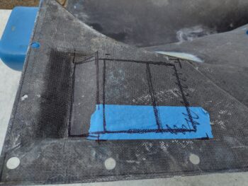
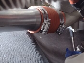
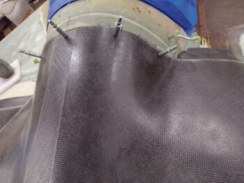
I started off this morning by drilling the holes through the front edge of the top cowling to allow me to install Clecos. I went with 5 fasteners, which will of course be CAMLOCs, since that’s what Mike Melvill used on his version of these cowlings.

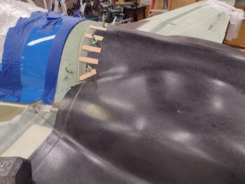
I wasn’t as concerned with the hole in the middle on each side, but then I figured the best way to evaluate the D-deck flange was to drill all the holes and get moving on all this.  To get to the middle hole on each side I had to clear away tape and some of the popsicle stick and cured hot glue.

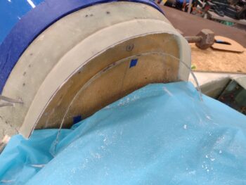
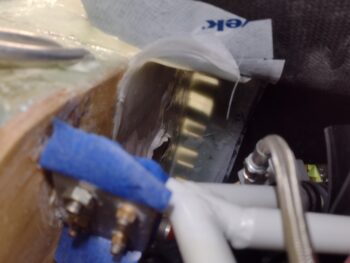
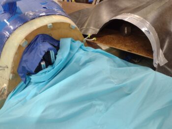
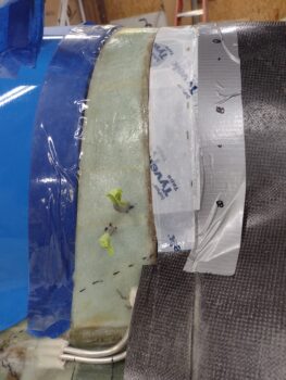
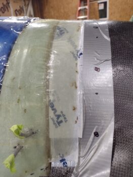
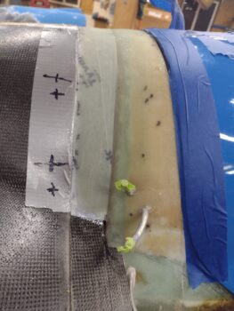
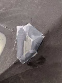
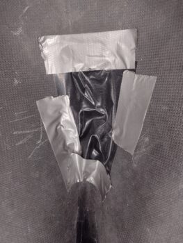
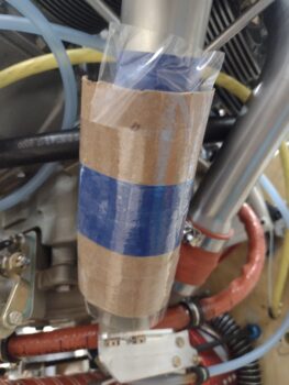
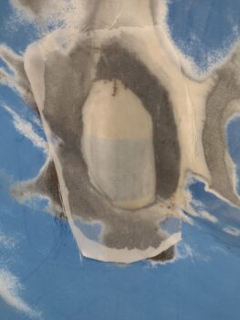
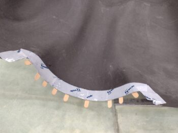
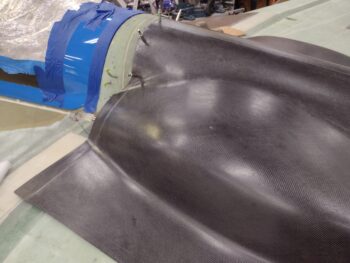
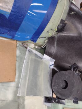
I didn’t grab a pic of this before the flange layup last night, but here’s my setup for creating the flanges/lips onto the cowlings.  This Tyvek house wrap tape is expensive, but it STICKS better than just about any tape I know… and it’s actually not too bad in coming off when its job is done.

Not surprisingly I reviewed my buddy Dave Berenholtz’s awesome blog on his cowling install before I dove back into my own top cowling installation.  Great stuff!

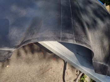
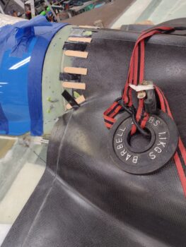
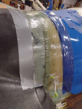
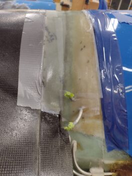
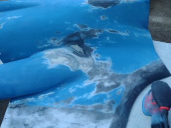
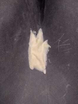
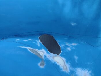
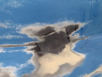
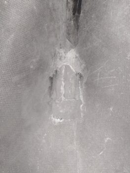
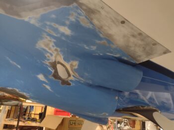
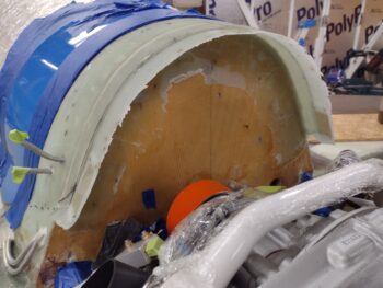
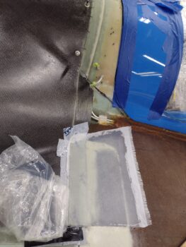
When I pulled the top cowling off this last layup and saw this below, a line Dave said as he was installing his cowlings popped into my head:
‘This is ugly building beyond description. A real, “do whatever it takes” to get a result approach.’

Hear, hear Brother… kindred spirits!

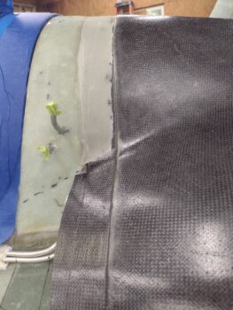
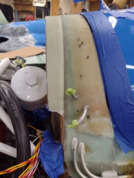
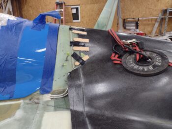
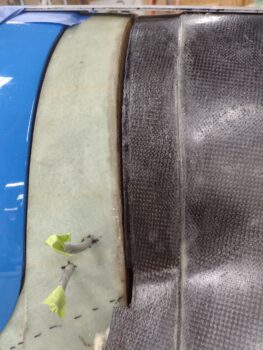
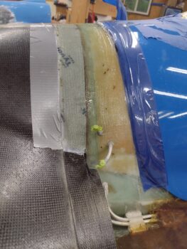
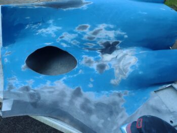
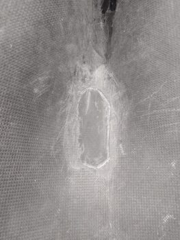
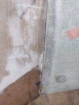
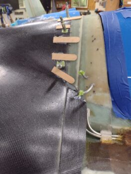
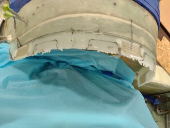
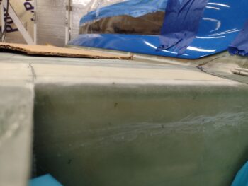
Clearly the good news is that the 5-ply flange layup glass stuck to the underside of the taped (and peel plied) top cowling.

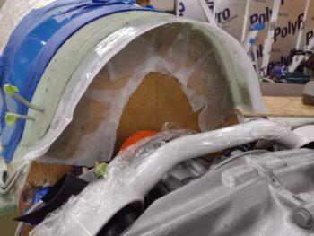
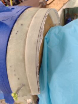
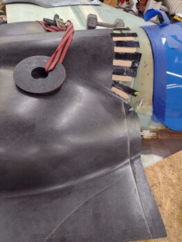
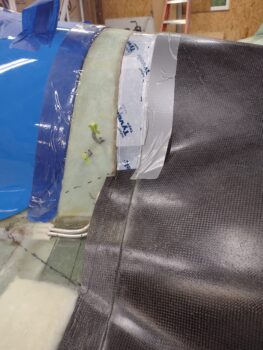
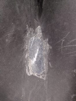
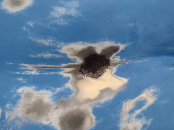
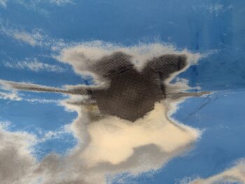
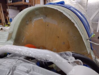
I then pulled the peel ply off this monstrosity of a layup… and I have to say that the flange width is not that bad at all!  Way more than I actually thought and besides a few possible touchup layups, will most likely work right out of the gate.

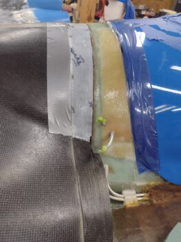
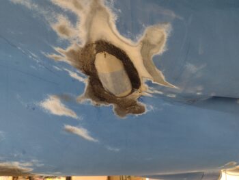
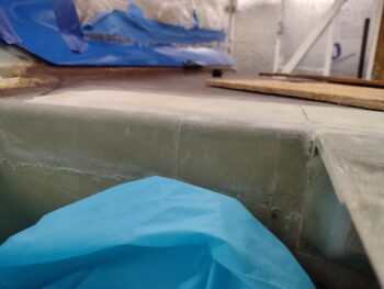
I had significantly more of an overlap onto the firewall than I needed, which is good because you can see some dead glass edges that will get trimmed away.  A few air pockets too that will either get filled with epoxy or simply cut out and a BID patch applied.  More importantly, the inside corners looked good with tight glass-to-glass bonding and no air pockets.

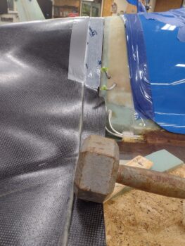
I then spent about 45 minutes (yes! … crazy) removing the hot glued-on popsicle sticks. I thought I’d get creative, innovative and smart by using a heat gun to remove them. Maybe that works if you hit the sweet spot of just getting the glue just warm enough to soften up to get off, but I found on the 2 tabs I removed it melted the glue into the weave of the CF.  And I still ended up spending time scraping off glue.

In the end it was just easier to resort to my old Neanderthal method of razor blade around the edges to remove the exposed glue, and then wood chisel to get underneath and physical tear the darn popsicle stick off.

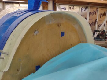
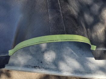
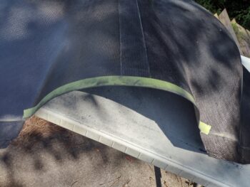
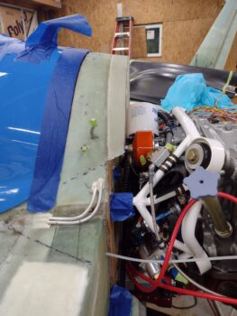
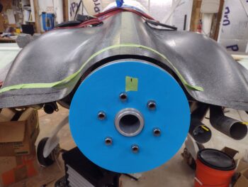
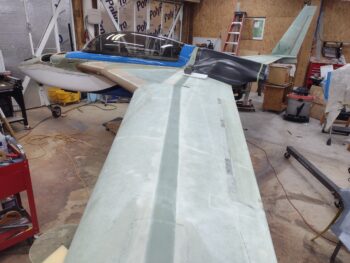
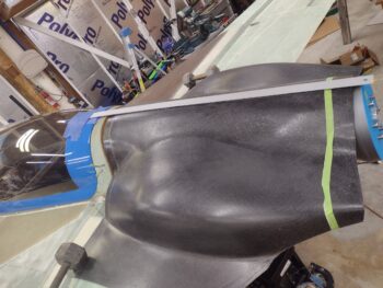
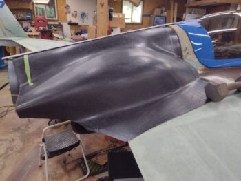
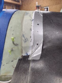
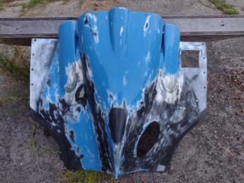
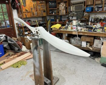
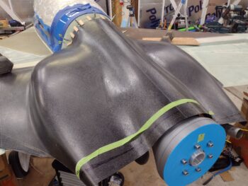
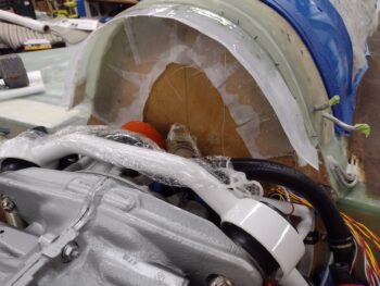
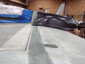
Anyway, with that done I put the cleaned up top cowling back in place.  Looking pretty good if I do say so myself!

And a side shot to check how our angle is doing…. the angle looks fine, but I don’t know if it’s the color differences or what, but the whole area from aft canopy to the end of the top cowling just looks really LONG to me.  Hmmm…  Maybe that’s why it’s called a Long-EZ?  (ha…. I know, just getting punch drunk from so much building!)

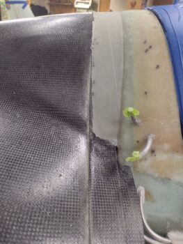
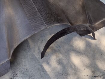
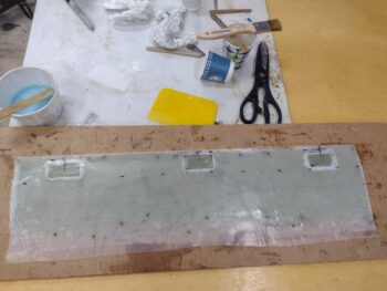
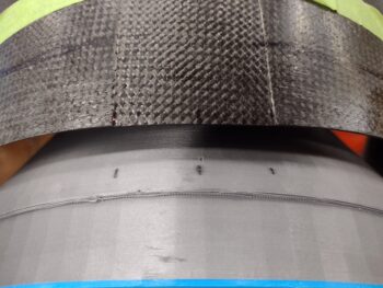
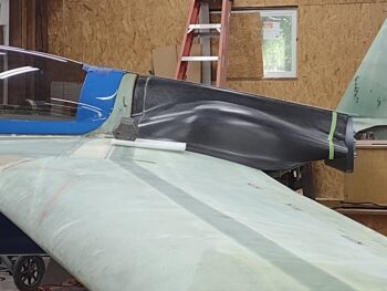
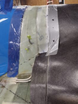
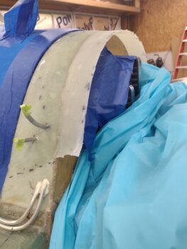
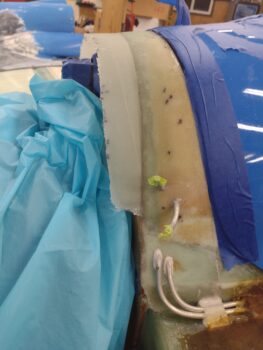
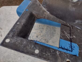
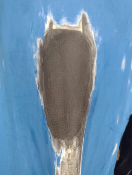
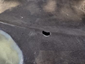
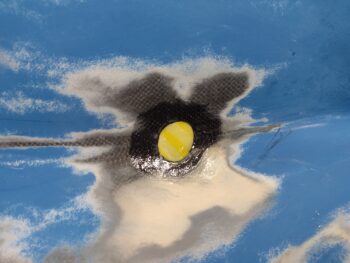
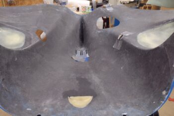
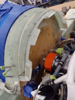
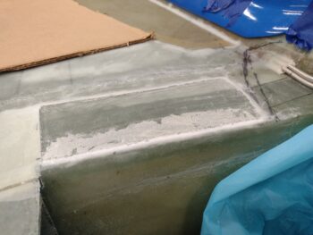
I then taped up the underside top cowl edges along the wings and the short length coming in from each corner to mark trim lines.  When the cowling came off and outside in prep for trim, I first took about 30+ minutes to mark up and trim the D-deck flange… in scalloped fashion as Mike Melvill did, mainly to allow more access to get into the engine compartment area and specifically the oil filter.

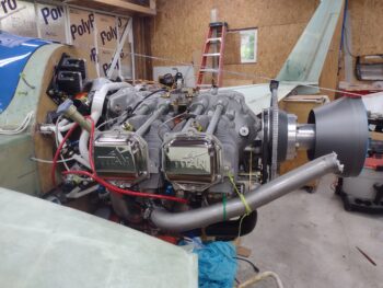
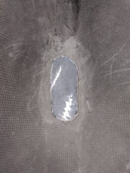
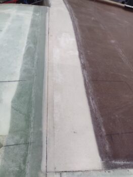
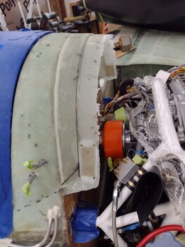
Using my trusty Fein saw and then Perma-Grit sanding tools I created this masterpiece (ha! … I TOLD you: punch drunk!).  Seriously, the 5-ply layup cleaned up acceptably nicely and I’m just happy that my calculated risk paid off and I didn’t have to remove the engine (as Jess noted: “High risk, high reward”… Yep!).

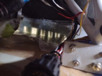
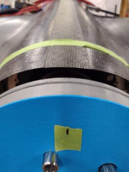
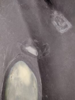
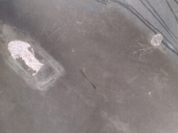
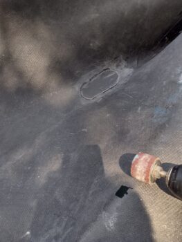
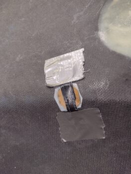
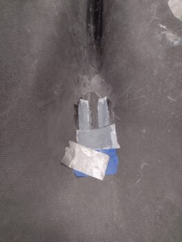
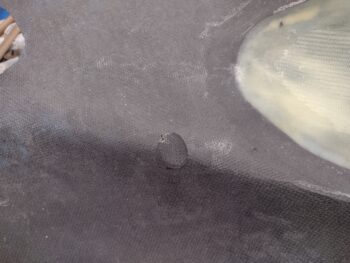
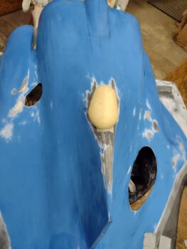
As you can see, my side G10 tabs dropped a bit.  I can still utilize them for the majority of the receptacle hole and one rivet into the G10, so not a total loss.  I’ll evaluate and ponder on this further to possibly reinforce them before installing the CAMLOC/SkyBolt receptacles.

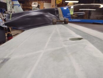
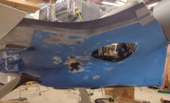
A sin of the immediate past was my CS spar fill with pour foam followed by 2 plies of glass, at least in the area just forward of the cowling.  I spent a good 1/2 hour with the top cowling in place looking at this and finally had to accept that I had called the elevation wrong and that it just wasn’t going to work: the foam and glass made the elevation way too high for plopping down 5 plies of BID and overlapping onto the lip of the cowling to match the (future) edge of the trimmed cowling.

After scheming and pondering various machinations, I finally just bit the bullet, pulled out the trusty Fein saw (it had better be at this point!) and went to work.

The primary concern here was of course “do no harm” to the spar cap of the CS spar.  That was one reason I left some foam on the aft edge of the CS spar before proceeding with my glassing.  The #2 reason was I still needed some fill to match the heights.

All told, it took me less than 10 minutes per side to get back close to previous state.

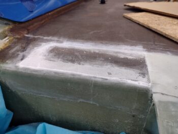
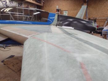
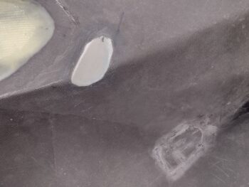
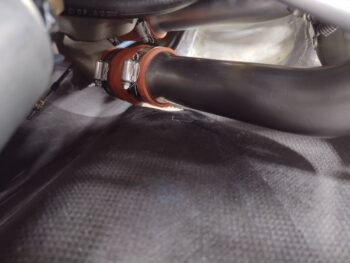
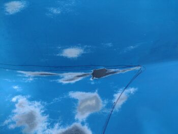
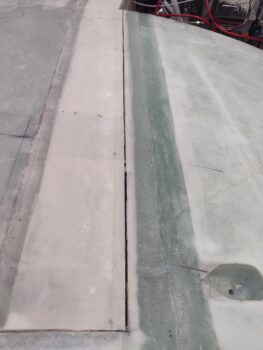
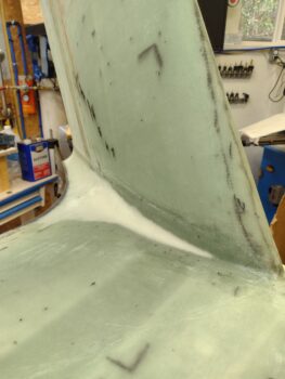
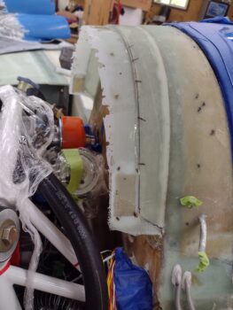
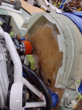
As you may be able to see above, there was a very small lip on the front side from the previous foam and glass. I knocked it down pretty good, but there was still just a bit left.  So I added an extra ply to the layup schedule for 6 plies total.  The first 4 plies of BID went up to the edge of that lip, while the last 2 plies not only went forward of that lip by about 0.3″ and 0.6″ respectively, but also a bit more inboard to help fill in and link the area where the top cowl shoulders will get filled in.

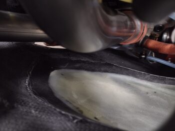
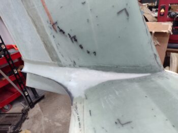
Honestly, besides adding a few extra grams in glass, both sides came out great and the level between CS spar/strake and cowling was spot on.  I also used wet flox on the remaining foam vs micro since I consider this a structural layup with it securing the top cowling that is constantly trying to be forcibly removed from the aircraft by on/incoming air.

Finally, there is about a 0.07″ height difference between this layup and the adjoining foam/glassed filled CS spar trough that I’ll have to contend with during finishing.

One last thought.  With my stepped approach to installing this top cowling I will probably need to get a lot more aggressive in dealing with the curve on the front edge of the trimmed cowling.  I didn’t factor that in when I made my plan to step through this install and I see now that it is a minor, albeit significant, fly in the ointment here.  Not that it can’t be worked through… I just have to account for it as a factor.

Pressing forward!


Chapter 23 – A bridge too far?!

The good news is that I met my strategic objective, but with some possible cleanup work (par usual eh?!).  I cover my calculated risk a bit below.

First, here are some shots of the initial situation of today with the stock plans lip coming off the D-deck and the top cowling set back in place.

My first actual build task this morning was adding a 1-ply BID layup to the inside of the 4-ply D-deck lip layup I did yesterday.  The reason for this layup is that I measured the cowl thickness at 0.065″ while the D-Deck lip (in 3 spots) measured about 0.054″ thick.

I prepregged a single ply of BID that covered the entire inside lip and overlapped onto the firewall around 1.5″.  I also added a small flox fillet in the corner for transition between the two sides of this essentially 90° corner layup.

I also used fast hardener here to get this thing cured as quickly as possible so I could get the next big layup in (below).  And I of course peel plied the layup.

I then trimmed the top cowling front —at the D-deck lip intersecting edge— to remove the current flange.

After cutting off the front flange I sanded the edge of the cowl straight and I thought all was good… luckily I picked up the cowling to take it back into the shop by this front edge.  It was then that I noticed there was a distinct inward curve leftover from the front flange joggle.

I didn’t want to remove any more than necessary, but this curved edge was not going to be removed by simply sanding it off.  So I took the cowling back into the shop, assessed it, and decided that 0.18″ was a good amount to remove 80% of this curve.  Then the other 20% could be easily knocked down with a sanding block.

So here is the final front cowling D-deck interfacing section trimmed to its final configuration.

Now it was time to trim the D-deck side lip.  The plans say go with a 1.6″ lip, but that was the only lip on the aircraft side that one had to contend with.  With the Melvill cowling you then need to essentially double that for the cowling to be “externally” mounted with CAMLOCs along its front edge.

That would result in about a 3″ flange, where you need to be able to get in and replace the oil filter —including safety wire!— in a somewhat already difficult area to access.  Compound this PITA with a 3″ lip??  Uh, no thanks.

As with everything on this bird, we typically “bargain” our compromises in 0.1″ increments, and here is no exception.  Every little bit counts.  So my proposed “stock” D-deck lip width here is around 1.4″ wide.  For the flange to secure the top cowling I’m looking at 1.2″ wide around the D-deck area.  This gets us from 3.2″ down to 2.6″… and while 5/8″ isn’t much, it can mean the world when trying to get a wrench or any tool into such a cramped space.

I used the just-trimmed top cowling as a template to draw the cut line on the D-deck lip. Makes sense right?  Since these will be the 2 interfacing edges.

I then used my trusty Fein saw and cut on the aft edge of the marked line.

And then used my straight sanding block to finalize getting the trimmed lip edge straight and clean.

Here’s where things got interesting and I had a big decision to make.  To really get a spot on layup of the 5 plies of BID that starts on the firewall at least an inch, then turns 90° and covers/attaches to the inside D-deck lip, and then extends onto the (taped at this point) underside top cowling a minimum of 1.2″ —to create the mounting flange to secure the top cowling with CAMLOCs— I would need unhindered access to the forward inside of the top cowling.

Meaning the engine would need to come off.

But that would mean I would lose both the dialed-in top cowl angle I have with it sitting on the 1″ foam block spacer secured to the flywheel AND my centering hash marks that I established with alignment ticks on both aft cowl edge and spinner flow guide (shown a bit below).  Hmmm?

–OR– I lay up as much of the 5 ply BID layup as far as I can, replete with peel ply, and then plop the cowling in place and reach up inside however able (and somewhat blind) to get the glass laid in as best possible.

I chose the calculated risk.

But what about this “Bridge too far” thing, you ask?

Well, I wanted to embed 1/32″ G10 into 3 of the 5 CAMLOC hardpoint positions on the top cowling lip that goes around the D-deck interfacing flange: the top center and lower CAMLOC on each side, essentially skipping the middle ones (#’s 2 & 4 out of 5).

My plan would have worked during a normal layup, but I missed one key characteristic of using prepreg on an inside corner layup around a tight curve… you have to cut the prepreg plastic to allow for all those compound curves, or it will just bunch up on you and you have to seriously fight the plastic to get the glass to lay down.  Which it will not do willingly [enter arguments for using foil here].

After I cut the prepreg plastic just prior to laying in the glass and pressed the glass into place, the cut plastic (not typical) couldn’t/didn’t maintain the original measurements.  Any fiberglass builder knows that trying to manipulate wet glass is like trying to push a wet noodle in a straight line…. it ain’t gonna happen.  And once it starts getting away from you, well, you have 2 options: go with the flow as best as you can, or pull the entire layup off and try to salvage it (and that too often ends up with all your glass and epoxy in the garbage can).

The resulting layup is one where it stretched on each end, diminishing my marked 1.3″ (remember 1.2″ was my goal, so a little wiggle room for trimming) flange width down to about an inch overlap onto the taped/peel plied underside of the top cowl.  From what I could see and feel I did get a solid grab on the underside of the top cowling, with no drooping.  I do know my flange is narrower than I planned and that my side G10 hardpoints are about an inch lower than where I had planned them to go… all’s fair in love, war and fiberglass layups!

Even better news is that my pre-hot glued popsicle stir sticks did their job and held the top cowling in place.  I had dry run this a couple of times and had hash marks here too to line up the top cowl to the D-deck lip.  The weights are keeping the very bottom of the sides pressed inward just about 0.06″ for alignment between the 2 surfaces.

This shot is specifically to show the canopy to D-deck to top cowling angle… personally I think this dawg will hunt and it’s looking pretty darn spiffy at this point!

Moreover, I was able to maintain the left right alignment both at the D-deck lip to cowl front edge up front and the alignment tick marks on the aft side of the top cowl as well.

Another shot of the aft top cowling alignment tick marks sitting pretty . . .

The top cowling aft curve around the flow guide isn’t perfectly symmetrically, but is definitely good enough for our birds.  Here you can see why I made and use those alignment tick marks to maintain the curved portion of the top cowling centered around the prop spinner/flow guide.

I’ll of course perform a Battle Damage Assessment on the glassed flange tomorrow after I pull the top cowling off.  I then intend to press on with the install of the upper cowling.

Chapter 23 – Top cowl install ensues

I started out today by setting the canopy in place on top of the fuselage.  I had thought about actually remounting it with the hinges in place, etc. but the amount of time and effort to actually re-install it wasn’t worth it… I know it sits a good 1/8″ to 3/16″ high without having the seals compressed and it being locked shut.

It still worked well enough for my purpose here, and that’s to check the angle between the canopy aft structure, the D-deck/Turtledeck and the upper cowling.

It may be hard to tell from these sides shots, which I guess is a good thing, but I have a 48″ aluminum measuring stick taped down to the aft canopy structure to assess the top cowling install angle.

Overall I think the top cowl angle is in line with the canopy aft structure and D-deck, but I do think my top cowl angle definitely drops down more sharply going aft than the standard that I see on other Long-EZs.

The plans say to have a minimum of 0.4″ clearance between the top cowling and the flywheel.  I have an inch.  I asked Marco to measure his gap and it’s 2″.  I may increase mine just a hair more, since even after I glass this D-deck flange I have some slight wiggle room in setting the top cowling angle.

Keep in mind in the pic below that the canopy aft structure is a hair higher than it would normally be closed, and that the Melvill cowling dips/slopes down slightly for a few inches going forward right as it nears this intersection (not sure why).

I then marked up the front edge of the cowling and did a few rounds of trimming to get it pressed up against the firewall evenly all the way around while still keeping my centering tick marks between top cowl aft edge and spinner flow guide aligned.

I hot glued 5 PVC foam tabs onto the firewall since I could then sand them at both proper angles to match the inside cowl surface and just a hair beneath the surface to allow for the thickness of the cowling… so that the D-Deck and cowling surfaces are even.

I also taped up the front lip of the cowling in prep for glassing this flange.

After a few quick dry runs and minor tweaks to the foam tabs, I then hot glued the top cowling to the tabs.  I actually added support underneath the outboard cowling edges before weighing them down as to not distort the middle portion of the cowling.

I’ll note that like I did on the bottom cowling, I’m installing the top cowling by glassing sections at a time.  Some builders, like my buddy Dave B., glass all these tabs in one go.

I’ll also remind ya’ll the deal with the Melvill cowlings: since he modified his flying airplane’s cowlings from standard plans —where the cowling front edge joggle fit underneath the fuselage-side lip to be secured with screws— to having the front of the cowling simply lay on top of the fuselage-side flange (no joggle) to be secured with CAMLOCs… to install his cowlings you have to follow in his footsteps by first installing the stock lip to then add the flange to allow the use of CAMLOCs.

The plans call for 5 plies of BID, but I’m only using 4 here.  The actual flange that secures the cowling front lip will get 5 plies.  In addition, I stepped the plies by 0.2″ to 0.3″ each ply to allow for a more gradual contour on the D-deck vs a 4-ply abrupt edge that would require more micro to fill.

I then prepregged the 4-ply BID layup.

I started the layup by adding peel ply to just the taped (white) flange area and wetting it out along with the D-deck surface receiving glass.

I then wetted out the 4-ply BID prepregged layup and set it in place around the D-deck/top cowl flange seam.

I’ll reiterate that, yes, both my fuselage and subsequently the canopy that sits on top of it are slightly “D” shaped (right side straighter than the left which has a hair more curve to it)… so the left side of the canopy/D-deck comes into this seam at a more distinct angle than on the right side, which is a few degrees shallower (aka flatter).
[#sins of the past]

I then pulled the prepreg plastic and worked the glass into place.

I then peel plied the layup . . . I’ll specifically note here that I both stippled the heck (as I normally do) out of this layup —especially when the peel ply goes on— as well as squeegeed it as well.

I say the above because I went out to dinner with Jess immediately following this layup, and when I returned I had a few small air pockets that were not there when I departed.  Jess’s work schedule can be a bit crazy, so I wasn’t sure if I would see her after dinner so I used fast hardener to possibly set up for another, subsequent layup tonight.  I note this because these few small air pockets may be the result of the quicker curing epoxy? (not sure….)

Anyhoo… with the layup cured enough to allow for easier removal of the peel ply I then decided it was probably better to remove the cowling at this point than with a full cure overnight.  I rapped the cowling on each lower side of the layup just aft of the D-deck and was able to wiggle it free in short order.

Here is the resulting flange.

I’ll assess both the interface and a bit more on the cowling angle tomorrow before I go final with trimming the flange off the top cowling and glassing the D-deck mounting lip for the top cowling.

Baby steps.

Chapter 23 – Sand the cowl you say?!

Starting off this morning I pulled the peel ply from the external side of the right side layup on the bottom cowling indention (inside… bump external) that provides clearance for the aft right cold air intake pipe.  I then cleaned up and sanded the edges of the interior side of the layup.

I then laid up strips of CF around the perimeter and peel plied the layups.  Only the edges need to hold since the entire layup will be covered in foam to shape the external side of the right cowling.

A few hours later I pulled the peel ply and cleaned up the perimeter layups.

I then remounted the cowling.

Here we have the best pics I could get showing the clearance provided by this protrusion.  The first pic is from the aft side, while the second is from the front side.

I then removed the cowling to outside the shop for some cutting and sanding, and on my way out of the shop to knock out my tasks I had this hitchhiker plop down on my shoulder.  I grabbed a pic of the friendly creature for my little buddy since she loves just about any animal and insect alive.

I also marked off the initial area to be cut out for the oil cooler.  I’ll fine tune it as I start the oil cooler install onto/above the lower cowling.

Here’s that area cut out.  I had to go back and look at pics to see how Mike Melvill had his oil cooler installed, thus the redraw on the cut line.  Again, I’ll dial it in during install depending on clearance, mounting fit, etc.

I then did a round of sanding on the lower cowling.  I bought a couple of sanders on sale (my DA sander is inop at the moment) at Harbor Freight, and am using up the included sandpaper before I go buy more.

After the first 45 minute round of sanding, I washed off the bottom cowling and set it in the sun to dry.  When I returned an hour later with the sun much lower in the sky, I noted how you could see right through the single plies of carbon fiber.  This supports my theory of a single ply acting as a “soft spot” (softer at least) for the CF air induction tube just in case there is contact.

A bit later I did another good round of sanding before again washing off all the sanding dust.  Clearly a good bit of the blue is coming off and I’m a day or two out from slathering up pour foam on the aft half of this thing and reworking the contour.

To be honest I really like the crazy look of this, but I guess “grunge” isn’t in style for Long-EZs… and since I’m the compliant type (ha!) I guess I’ll bend to peer pressure and paint this thing proper!

It was yet again a very hot day, and I was drenched with sweat from head to toe… but with the weather not getting any cooler at the moment I went ahead and soldiered on. I plan to start the upper cowling install too and work the final cowling installs in tandem to ensure I get the upper and lower clearances and spacing as symmetrical as possible.

With that, I headed into the house to take a well deserved shower and then did some much needed grocery shopping!

Pressing forward.

Chapter 19/23 – Final wing rigging

I started off this very long build day by ripping the peel ply off the bottom of the lower cowling where I had laid up 1 ply of CF to create more clearance and a “soft spot” for the CF air induction tube.

I then cleaned up just a bit around the edges.

I had used Gorilla duct tape inside the bottom cowling as a dam for the pour foam that allowed me to glass the CF layup above.

After removing the tape dam, I then removed all the foam to reveal the clear packing tape I had put over the foam… I then removed the packing tape which revealed the peel ply.

Finally, I removed the peel ply and cleaned up the edges of this relief layup.

I then took the bottom cowling outside to do some work on it.  First up was using a round sanding wheel to make a round shaped divot into the left corner of the cowling to add a bit more clearance for the aft left cold air intake tube.

Here it is after I used the sanding wheel… more of a round shape to match the cold air intake tube. It’s even angled close to how the tube flows.

Here’s the same thing on the outside of the cowling.  I also trimmed just a hair more out of the hole on the right side for the aft cold air intake tube on that side as well.

I then did about 10 minutes of sanding on the bottom cowling to start removing a bunch of the paint for some major upcoming cowling contour rework.

Back inside, I made a small cardboard disk “saddle” mold (or plug) for the small left side cold air intake tube clearance divot.  Before I taped it in place I added a layer of peel ply.

As you can see, I did yet another round of aggressive sanding on the lower cowling, specifically in the areas that would be getting layups.

I then wet out the peel ply over the “saddle” plug and the surrounding lower cowling, and then laid up 1 ply of carbon fiber.

I then peel plied the CF layup.

At the same time I did the layup above, I also laid up some narrow tapes of perimeter CF and a decent-sized patch on the forward end to secure the CF air induction tube relief layup in place.  I also peel plied that (the tape is due to one corner of the peel ply being stubborn and not laying down).

I grabbed a wide-angle shot not only to show the 2 lower cowling clearance layups, but also to show the very different left and right sides of the bottom cowling.  I understand this is forced in many respects due to needing clearance for the alternator, but the cowling is very unsymmetrical with the left side (right side of pic) much lower than the other side.

Jumping ahead a number of hours, here’s that same layup after it cured and I pulled both the peel ply and the cardboard mold off the cowling.

I of course pulled the tape and peel ply off the CF air induction tube layup and cleaned it up as well.

Last night I added and swapped washers on the left wing, obviously requiring removing the left wing to get those on.  Subsequently, today, I removed the left wing again to add/ reconfigure the washers while also removing the right wing TWICE as well to finalize the washer configuration between left and right wings!

Besides refining my wing removal and mounting processes, I can now say definitively that I’m very pleased that I decided to go through this exercise.  A friend of mine recently started flying a new canard and had to really tweak one wing into place vs its previous “final” position —something we all pray doesn’t happen to our birds!  The resulting pivot to get the plane to fly straight left about a 1/4″ gap between the strake and wing on the leading edge.  Clearly, in part my effort here is to be diligent, with the goal to have a straight flying Long-EZ (ok…. and NO large gaps, if I’m being honest!).

I actually had a brain fart last night on the left wing washers when I simply added in a thin washer (~0.032″) at the inboard bolt and swapped out thin washers outboard for thicker washers (~0.065″).  It definitely made an in improvement and helped close the ~1″ difference between left and right wing position identifiers (outboard forward aileron corner and point on winglet-to-LE corner) by over 5/16″, but it didn’t result in any pivot or rotation of the wing, which I was actually after.

Today, after I left the thin washers in position on the outboard side of the right wing, and put a thick washer in the inboard spot, I noted that the numbers didn’t change much (other than right at the wing root and a small bit between measurements to the nose). Why did the left wing washer reconfiguration seem to have more impact than the right?  Ahh, (face palm) because I simply moved the entire wing aft 1/32″ (no pivot).

My errant fix action on the left wing last night was actually serendipitous in that it made me realize that simply moving the wing aft (or forward) appeared to have significantly more impact on my numbers than pivoting the wing (with the washers at least).

After some more hard thinking (for me), I put the right wing bolts back to all single thin washers.  On the left I swapped the thin washer inboard for a thick washer, and then doubled the thick washers on each bolt (total 2 ea) on the outboard bolts.  This negatively affected my nose to winglet/wingtip measurements a bit (~1/8″) between the 2 sides, but it just about hit the bullseye on making my wing alignment fore & aft (and sweep) spot on.

In addition, here’s some fuselage-strake-prop measurements for FYI . . . From the front of F28 to front edge of the “prop” measured 136.75″ on both left and right sides [Note: I measured 23″ out from A/C-engine CL both directions and marked these points on my “prop”… all prop-face measurements were to these respective points].

However, from the front of F28 each side to the aft edge of the CS spar measured 38.75″ left and 38.56″ right.  Interestingly, from the nose to aft CS spar edge they swap longest lengths with the left 98.5″ and the right 98.63″.  This actually makes sense since I had to do some significant machinations to get my nose dead center on the front of a wonky fuselage!

I of course wanted to ensure to get the wing sweep/fore-aft alignments completed before micro-finishing the topside strakes and wings ⇒ especially the intersections.  As you can imagine, the thick washers on the left wing kicked it out a decent bit.  No worries of course since none of it has been micro-finished and can be tweaked to get the line back narrower.

On the right side my total change was adding a thin washer to the inboard bolt, which I believe I had when the plane was upside down (not sure why I didn’t have them this time around?).  The impact to the right wing-to-strake seam was of course pretty much nill.

Now, since I’ve been using props with quotations for the last couple of blog posts, let me segue that into letting ya’ll know how excited I am to report that I snagged a backup Hertzler Silver Bullet prop —same dimensions as my primary SB prop (66 x 75)— from Nick Ugolini.  This is the pic he just sent me showing me that the balancing and painting is complete!

Moreover, I plan on visiting Nick in the next few weeks to not only pick up the prop, but to also do a little transition training in his Cozy IV.  Woo-hoo!

Next came a big test: did my wing bolt washer shenanigans totally throw off the fit of the lower cowling??  Thankfully NO!  Apparently there’s enough flex in the cowling that although a couple of the forward Cam-locs felt tighter, they still went right in.

With the lower cowling in place, I took a minute to grab a shot of the left side divot I made to allow a bit more clearance for the left aft cold air intake tube.

I then wrapped up the right side aft cold air intake tube with a couple plies of cardboard, then some clear packing tape.

And taped a piece of peel ply to this cardboard form in place underneath the opening in the cowling.

It was very late and I didn’t want to haul down and unwrap the CF roll at this point for such a small, singly-ply layup… so I just used a scrap of BID (pretty much all of this layup will be covered by pour foam).  I wet out the peel ply and the surrounding surface of the lower cowling first, then I laid up the ply of BID.

And then I peel plied the BID layup.

And with that, I very much had a glass of red and called it a night!

Chapter 19/23 – Holie bottom cowl!

I didn’t do a blog post yesterday because it was all about research.  Over about 12 hours worth, including old 1980’s Sq. III videos with Dave Ronneburg and David Orr (aka Beagle) on cowlings, baffles, etc.  Ahh, if I had only watched those in year zero!

With the bottom cowling on, I grabbed a very long 1/8″ drill bit and chucked it up.  Then I drilled 3 holes in the cowlings that marked the most critical components suffering from lack of clearance between them and the lower cowling.  Those components (marked with arrows on green tape) are:

1.  The centerline carbon fiber air induction tube.
2.  The left inboard exhaust pipe 90° elbow.
3.  The left cold air intake tube (the right side is already cut).

My initial plan for the centerline carbon fiber air induction tube was simply to extend the structure of the belly RAM air scoop to end [externally] just a bit aft of the cold air induction tube [internally].

I first found and marked the centerline of the bottom of the lower cowling.

And then marked the proposed extension of the aft RAM air scoop structure, or swoosh if you will (technical term).

First I had to locate exactly where the carbon fiber air induction tube wawouls situated in relationship to the cowling… so I drilled another bigger hole, mounted the bottom cowling and took a peek.

From there I used my trusty Fein saw to cut out an oval peek hole.

I then needed to make a decision.  You see, the tightest clearance between the carbon fiber air induction tube and the bottom cowling is about 1/8″.   And that is literally for maybe 1.5″ going forward.  From there the remaining air induction tube has a decent amount of clearance.

My secondary plan, which would be way easier and much faster, was to cut a relief hole in the bottom of the cowling to then recover with CF.  Since the average thickness of the cowling is about 0.07″, then if I relocate the “floor” underneath the very aft portion of the carbon fiber air induction tube to the existing exterior surface of the bottom cowling, I could then reclaim that 0.07″ of clearance…

I know, I know!  Barely nothing.  But that would then put me at just under 0.2″ of clearance.  Plus, since I’m only using enough carbon fiber (1 ply) to cover this relief hole, then there is a bit more give than the much thicker cowling.  Essentially what I’m creating is an oval “soft spot” on the bottom of the cowling that when painted will be indistinguishable from the rest of the bottom cowling; will keep the air in; and will have a considerable bit more give if “pushed around” by the more stout carbon fiber air induction tube.

It took a few iterations to get the clearance dialed in.

Pert near final!

I took the lower cowling outside and did a fair bit of sanding on it before bringing it back inside and cleaning it up.

I then taped inside the hole with some thick duct tape.

And slathered some pour foam into the hole.

Baking some more bread!  (A side view).

About 10 minutes later, after cure, I then hacked the foam down before sanding it to match the bottom cowling surface.

I then applied clear packing tape to just the foam area.

And also a layer of peel ply that was cut the same shape and size as the foam.

I then laid up 1 ply of CF (see the horse head? Hint: it’s sideways)

I then peel plied the layup.

To be clear, if after flying for a bit I notice any significant chaffing, rubbing or contact between the CF air induction tube and the cowling, I will then employ my initial plan and take the RAM air scoop aft end all the way to nearly the end of the bottom cowling boat/shark/rudder tail to ensure the required clearance is on hand. 

As the first CF layup was curing, I then notched the left side divot that will allow just a bit more clearance for the cold air intake tube.

I then added a “propeller” to my bird.  I noted that in the propeller installation instructions it says to check the distance of the prop from the TE of the wing on each side to see if the prop is rotating in a perfect circle perpendicular to A/C centerline.

I decided to investigate the dimensions of the prop not only on how it aligned with the wing on each side forward of it, but straight out 90° from the prop hub.

That’s when I fell into yet another rabbit hole. . . (they’re everywhere on these builds!!!)

If you remember about 10 months ago, before I mounted the winglets I did a deep dive on if my wings were straight and equal to each other.  Since I hadn’t installed the winglets yet nor did I have the engine installed, I didn’t have nearly as many solid data points to refer to on just how the wings were looking.  Back then they looked great and I determined —in many different directional dimensions— that they were only 1/16″ off in length from each other.

Okay, great!

But when I ran a straight line along the front surface of my “prop” . . . whoa!!!! Did I find a different story!  I made a not so pleasant discovery and was staring down the barrel of my wings being off in F.S. (Fuselage Station), sweep, whatever you want to call it, by a good inch [read below as I clarify this statement].

Now I will note that my first assumption from my previous confirmation (mentioned above) was that my wings were of course straight, it was the engine that was off kilter (not up/down as before, but left/right).

However, after taking a myriad of measurements I confirmed that my engine is exactly in line with the fuselage.  So it is a bit of an odd situation.  The engine is almost dead on with the fuselage, but it is off when compared to the wings (since the wings are off from each other).

To convey just how off they are, the straight line out 90° to the LEFT/port side from the prop hub and along the straight “prop” I have temporarily installed has the line crossing the forward outboard corner of the aileron just kissing the corner.  Conversely, on the RIGHT side the line crosses the outboard forward aileron corner an inch forward of that corner.  The same goes with the intersect point from “prop” to each winglet, with the right side being about 1.2″ forward than the left.

“Strange things are afoot at the Circle K, Ted!”  

It gets weirder.  Interestingly, all the flying surfaces are dialed into the nose. When I measure each wingtip, aft top winglet corner, etc. to the nose, I’m at most 1/8″ off between them one side versus the other.

Finally, I’ll report that the CS spar/strakes are a hair over 1/8″ off perpendicular to A/C centerline.

I did a quick dive into the plans on wing sweep, which can be up to 3″ off between wings and Burt says a Long-EZ will still fly just fine.

I also removed the left wing, added a thin washer inboard and a thick washer (vs thin) per outboard bolt.  I intend to add/swap washers to the right wing as well… more to report tomorrow.

For now…. yep, I’m calling it a night.

Chapter 24 – Top of Winglet Fairings

Before I got serious about prepping the boat for a day out on the water, I spent about 45 minutes in the shop pulling peel ply off the cured layups on the top halves of both the left and right winglet intersection fairings.

I then cleaned up all the peel ply boogers left from the peel ply edges & seams.

Cleaned up the edges of the layups at the transition of new glass to old glass.

I also razor trimmed and sanded the inboard “TE” of the fairings.

And sanded the very aft curved trailing edge to clean up the glass and avoid any puncture wounds.  I’ll trim to final length probably after the bottom side of the fairing is finished (I’ll assess).

I also sanded down the top of the vertical “wall” that rests against the rudder to remove any spikes and potential finger pokers, on both sides of course.  I’ll trim the edges of these inboard “walls” to the same height on both sides within the next day or two.

And that was the extent of my airplane building today.  Again, I am very pleased with the way these winglet fairings turned out.  Of course building two separate components like this about 25′ apart means that there will be minor variances, and there are… but I’d say that they match each other by over 95%.

Tomorrow I’ll jump back on the build!

Chapter 24 – Winglet fairings glassed

Although not quite as hot as yesterday, today was still darn hot.  With activities limited to indoors (by me!), today was all about getting the topside winglet intersection fairings glassed.

Of course this meant first that I had to foam and shape the left side fairing.

As I did on the strakes, I simply cleaned up and flipped the tape-covered-cardboard dams that I used on the right side to pour the left winglet intersection fairing foam.

Note that as I did on the right fairing, I have the cardboard dam sitting on the edge of the fairing to keep a good 1/4-3/8″ bare edge (no foam) for ensuring a glass-to-glass seam along this fairing “TE.”

After getting the dam in place I then mixed up and slathered in 2 batches of the pour foam.

After the foam cured, I then started by trimming off the top with the wood saw before I then removed the dam.

A bit more major foam removal with the wood saw.

And then the first couple of rounds with the 2.8″ diameter fire extinguisher mounting “cup” (that I’m not using now) with 50 grit sandpaper wrapped around it.

After a few more rounds, including some smaller diameter Perma-Grit tools, I finally had a pleasing shape for my fairing.  I also tweaked the right side contour just a hair as well.

It was now time for glass.

First I want to share with you what I read recently on the COBA canard forums, where a guy mentioned that every pound he added aft of the firewall meant he needed 1/2 a pound of ballast in the nose.  I don’t know how specifically accurate that is but lately, between his comment and Klaus’s admonishment on build weight, I’m re-motivated and have been on a “diet” with the bird in regards to weight management (if only I myself could be so disciplined!).

I mention this to say obviously that I want to add as little weight as possible on these fairings.  Thus on the front half of the first ply I decided to use UNI vs BID simply because it’s a bit lighter.

On the aft side for the first ply I chose BID because I want to reinforce the “wall” that makes up the aft 1/3 of the outboard vertical component of the fairing… immediately adjacent to the rudder.  I also overlapped this aft BID a good inch forward of the front vertical edge of the rudder so that it would be secured to the actual winglet.

This ply of BID also overlaps just a bit onto the UNI.

Ply #2 is simply a single piece of BID that covers the previous plies and of course the entire topside winglet intersection faring.

After adding micro/slurry to the foam and wetting out the surrounding glass edges, I first laid up the forward ply of UNI, then the aft ply of BID.

These steps are representative of what I did on the right side as well.

I then laid up the top ply of BID and wetted it out.

And then peel plied the entire layup.

Again, I did the same thing on the right side.

I’m very happy with how these winglet intersection fairings turned out… I think they look pretty darn snazzy and the weight penalty isn’t bad either.  I’ll gauge the rigidity of fairing, but my initial thought right now is that I’m only going to use a single ply of BID on the bottom of the fairing over the intersection foam.  I’ll confirm that after these layups cure overnight.

Tomorrow is supposed to be another hot day, and I’m simply not going to cover up and wear a mask, etc. to sand down carbon fiber on a hot day.  Moreover, since I’ve been hard at work on the plane build for weeks solid now, it’s time to take my girl out on the boat for a nice day on the water.  In short, not a lot of plane-building is going to get done tomorrow.

Chapter 24 – A pleasing shape!

Today was another very hot day, so no bottom cowling sanding yet.

I started off by simply pulling the peel ply, razor trimming and cleaning up the reinforcement layups on the right pilot armrest interior surface.  I’m happy to report this task is complete and pressing forward!

I also got another round of glassing in after cleaning up the corners and edges of the now attached CF-covered wood substrates making up the winglet intersection fairings.

After prepping the underside areas on both the left and right winglets/wings I prepregged the BID before laying it up.

First the left side . . .

And then the right.  Of course I peel plied the layups as well.

On the right winglet intersection fairing I constructed a dam on the top side for pour foam.

I then added in pour foam in 2 batches.

A bit later I pulled the dam borders off the cured pour foam.  Yes, it’s always way more foam than you need just to get everything covered.

I then took my trusty wood saw and started hacking (or sawing!) away.  After a few rounds in just a few minutes I had whittled the foam down a good bit.

I wanted a tubular object that was around 3″ in diameter to start my sanding & shaping with, and then planned on going smaller in diameter from there.  My previous fiberglass tube that I glassed for securing the fire extinguisher in the past measured just over 2.8″ in diameter… perfect.

I then wrapped it in a sheet of 50 grit sandpaper.

And went to town.  Here are a couple of pics after a few rounds of sanding, followed by some cleanup with the shop vac.

I got to a good stopping point after another few rounds of sanding to come back to tomorrow to finalize the shape.  It was getting late and I was hot and tired, so I wanted to reassess the final shape tomorrow before glassing this top side fillet on the right winglet intersection fairing.  Note that these pics below are all to the same level in sanding.


I’ll also note that I only did the right side —from foam pour to sanding— just to ensure that I didn’t miss anything or screw anything up!  Tomorrow I’ll do the left side and sand/shape it before glassing either side just to ensure the contours and profiles are the same on each side.

Again, in a way I’m just filling time waiting for slightly cooler weather to work my #1 priority: the bottom cowling, and in turn the exhaust pipes (yes, still… sigh).

Chapter 23/25 – Cowl glass required

Today was about knocking out some glasswork for upcoming tasks as well as remounting the lower cowling and assessing clearances with the engine now back in its original position.

Starting off, the outboard edges of my strakes tend to dip down right in the last 0.5″ inch around the perimeter of the strake edge.  This dip of course causes there to be a more pronounced uneven skin height level between the wing and the strake.

Instead of just slathering on a bunch of micro, flocro or flox, I wanted to both stiffen this edge up a bit while giving it some increased height to better match the wing.  On the end of both strakes I determined different thicknesses of BID that I was going to add, ranging from 1 to 5 plies.  3 plies was the most common addition, while I only needed 5 plies in one spot on each side, both about 3/4″ in length.

The width of the added BID started out as 0.4″… clearly it varied a slight bit as I manipulated the layup around the leading edge.  After prepregging the BID and getting it laid up, I then peel plied the layups.

A few hours later I pulled the peel ply and cleaned up the layups.  I may add another ply or two to the still considerably depressed spots, but the majority of the areas I’m calling good and feel comfortable with still a decent application of micro on the edge now.

Another glassing task that I have on my list that needed to be done before I consider this bird operational is a reinforcement layup on the pilot right armrest.
[I have just under 20 layup jobs that I’ve identified that need to be done (each task may require multiple layups).  About 75% of those must be done before the airplane goes airborne, others are mods such as baggage pods, wing LE landing lights, HUD mount bracket, etc.]

The plans call for 2 plies of BID, but I only used one.  Now I’m reinforcing the center area where I will push down when extracting my less-than-Twiggy self and getting into this bird.

Plus it was a fairly quick kill and I was trying to get out the door to meet Jess for a late dinner.  Not surprisingly, all the glass & CF I used were scrap pieces.

Here’s both sides of my Lantor Soric test piece that I laid up 1 ply of BID on each side.  One side was peel plied, the other not.  Yes, there’s air gaps around the perimeter where having a micro (or flox) transition would be good of course.

With a ply of BID on each side the thickness came out to almost 1/8″.  Also, as you can see on my well used scale (it means I’m building a lot! … ha) my ~2″ x 2″ test piece is a whopping 8 grams.

If you’re wondering why I’m interested in this Lantor Soric stuff, it’s because it will be the material that I most likely construct my wing/aileron fences out of… so far so good!

After returning home from dinner, I tucked away all the dangly stuff on the engine to allow me to mount the bottom cowling to assess clearances.

Yes, the gap between the spinner flow guide and the lower cowling is much tighter now, at just over 0.45″ … but I can manage that with no serious effort.  The big issue is the inboard left exhaust pipe, which the bottom of the 90° bend is now touching the cowling.  Moreover, my carbon fiber induction tube is just a hair away from the cowling as well… although not touching!

If you look closely you can see black Sharpie marks all over the bottom cowling.  I spent a good 45 minutes assessing my next steps, and yes… I will be recontouring major portions of the aft, mid to upper areas of the bottom cowling.  In addition, I will be extending the tail end transition of the RAM air scoop all the way to about 10″ in front of the boat tail “rudder” fin.  This is the only way I can see to add in some clearance to the air induction tube on the bottom of the cowling without a total rebuild.

More to follow of course, and I plan on getting started soon.  But we’re having another major heat spell… I went to have a glass of red and ponder my bottom cowling fix actions on the front porch at 11pm tonight and it was over 90°. . . clearly just too darn hot.  My point is that I will not be doing a lot of sanding on the bottom cowling during super hot days, so it may be a few days before I get a somewhat cooler day to knock that out.