Chapter 20-23 – Threading the Needle

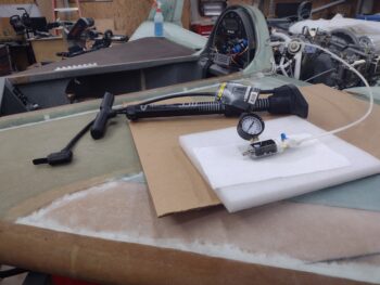
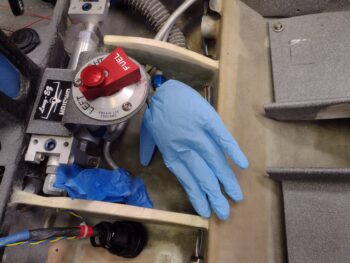
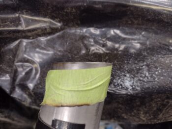
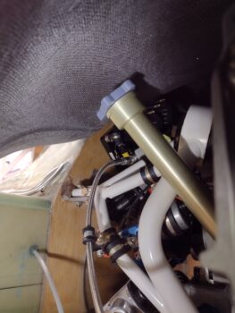
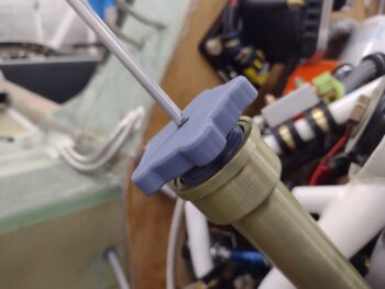
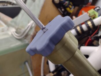
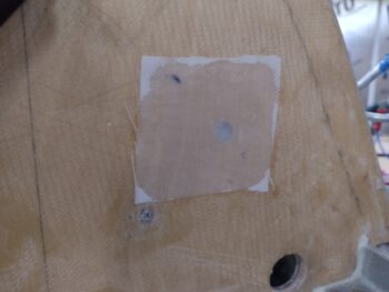
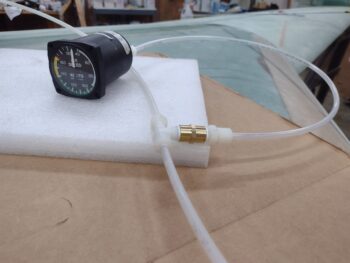
Late last night when I got home from a quick late dinner with Jess, I was annoyed that the previously inflated blue glove for my right fuel tank pressure test was totally flat. On a whim I blew in the tube again and set the right fuel tank pressure to about 100 knots on the air speed indicator, and had a decent inflation in the blue glove.  I then closed up shop and went to bed.

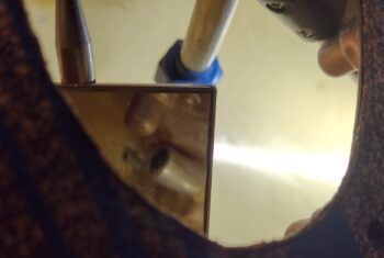
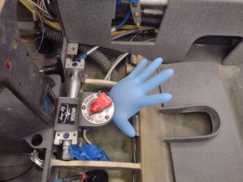
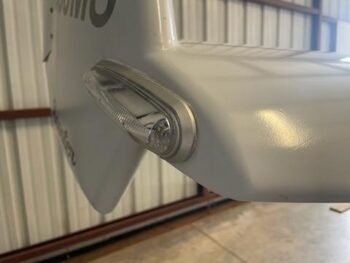
Well, this morning, having forgotten about it to some degree, when I went out to the shop 11 hours later I was pleasantly surprised that glove was still inflated nicely.  I then snapped this shot at 15 hours later, as you can see.  For some reason the glove stayed inflated this time around, and I’ll take it!

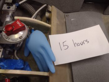
Of course the ASI read 0 and I suspect it might be part of the problem as it allows for a slow leak.  I will most likely do another round of pressure leak tests before finishing the top strakes, and also after the gas caps are in… only with Freon to ensure there are really no significant leaks.

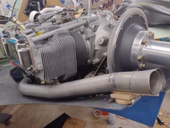
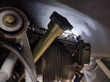
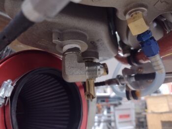
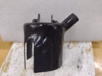
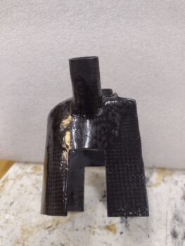
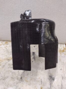
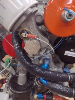
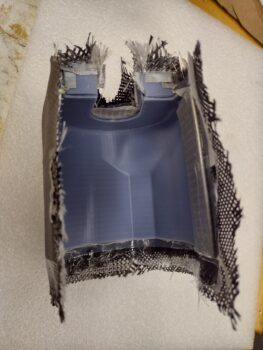
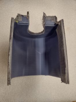
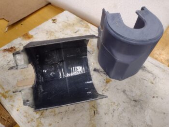
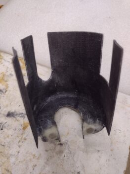
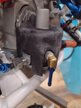
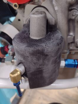
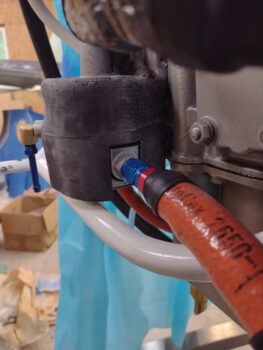
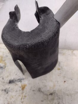
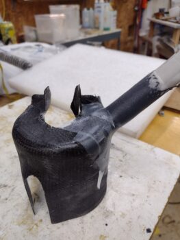
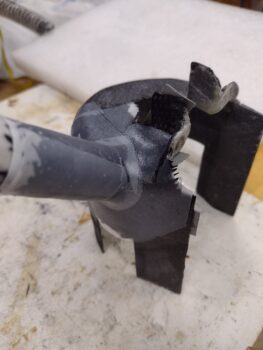
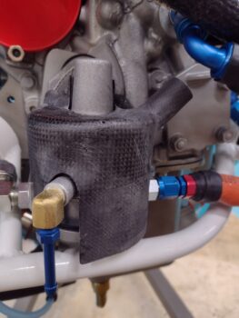
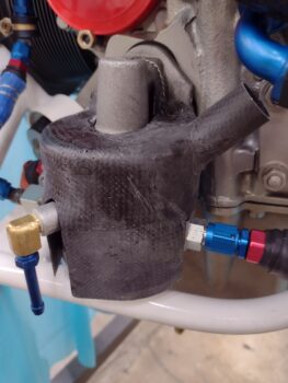
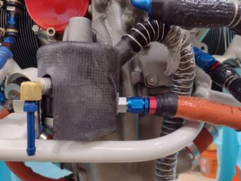
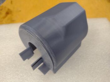
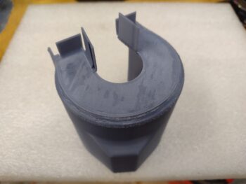
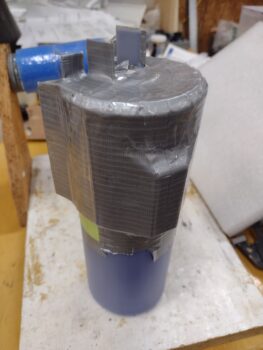
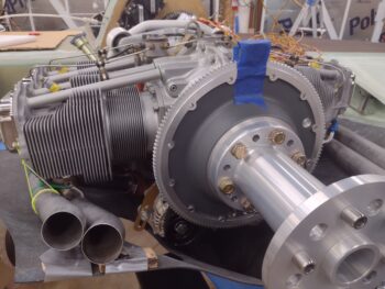
In more good news, I received the invoice from E-Mag Air and paid them for shipping to send the PMag back.  In the next 2-3 weeks I’ll most likely have the engine back off the bird, and then will re-install the PMag back into its spot.  While the PMag is off the engine I will make a cooling shroud for it as well.

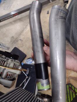
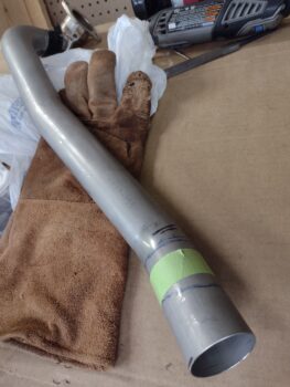
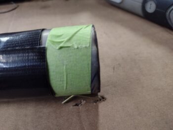
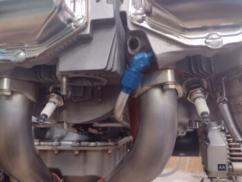
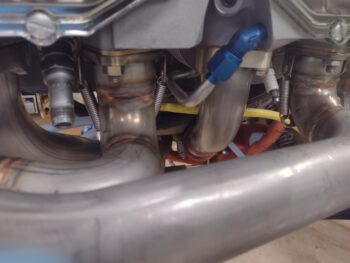
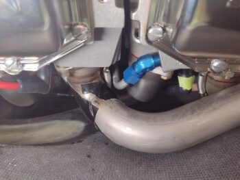
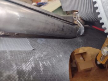
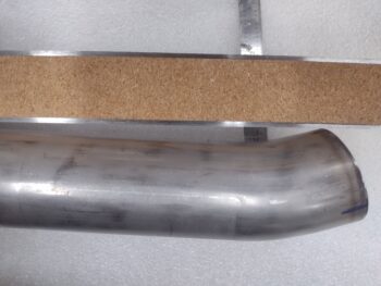
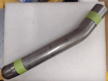
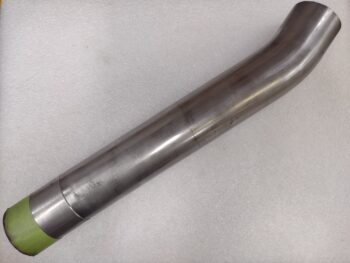
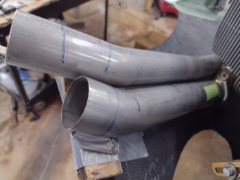
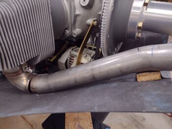
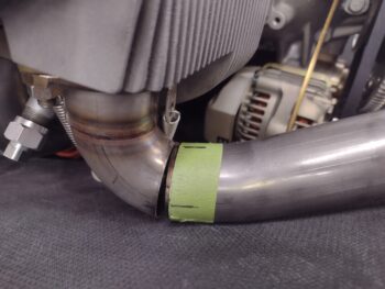
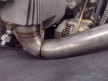
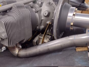
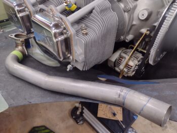
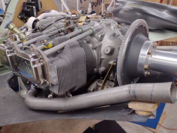
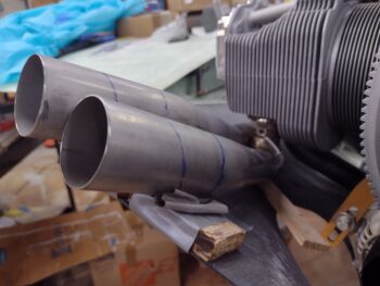
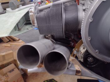
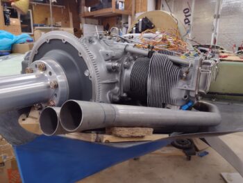
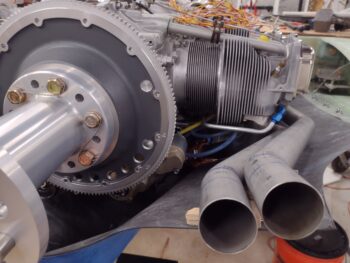
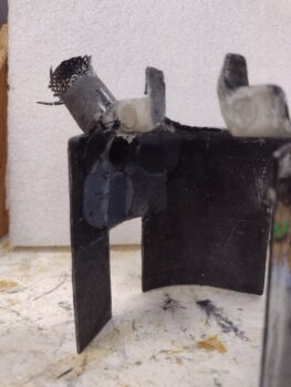
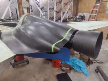
As for the exhaust pipes: I’m done trimming the pipes for now.  I ordered some ER347 filler rod for 321 stainless and plan on tack welding the pipe(s)… first the inboard pipe, and then the outboard pipe to nest as close as possible to the inboard pipe.  I may not actually tack weld the outboard pipe, but will clock it and mark it for James to weld it up.

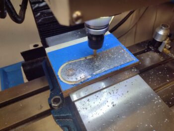
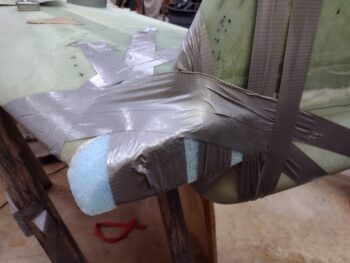
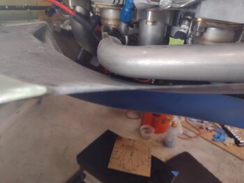
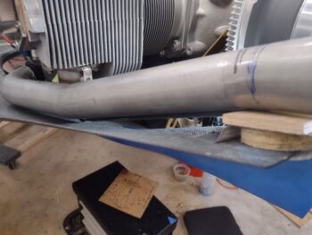
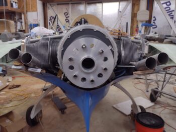
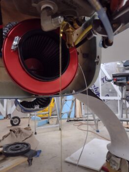
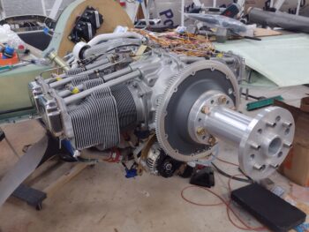
I then taped a 1″ piece of foam on the top of the flywheel as a gap for the top cowling.  I want to check the exhaust pipes’ elevation with the top cowling in place since I don’t want to end up with the pipes too high in relation to the top cowling.

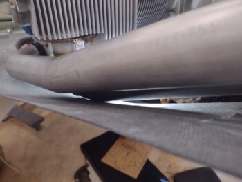
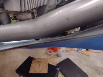
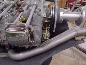
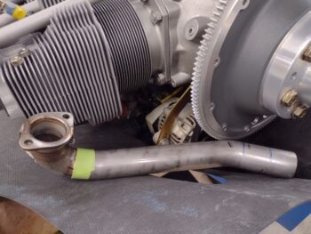
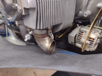
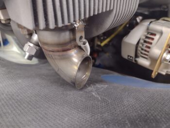
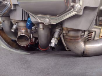
The title of this blog, “threading the needle” is in reference to the aft opening of my cowlings and the exhaust pipes’ exit out of them.  I may have the narrowest cowling exit on record for a Long-EZ!  I will also note that there is a decent probability that I will be modifying the exhaust pipes even more since they will most likely need to be angled more inboard towards the prop hub.  About one pipe diameter inboard as to where they are now… the outboard slit (aka cowl opening) will be very tight with only about 1/2″ clearance above and below each pipe.

Since the right exhaust pipes come inboard more anyway, they are not quite as bad as the left pipes.

As I did some research, I noted on my buddy Dave Berenholtz’s site that his lower cowling is about 1″ lower than mine at the very aft end if you measured his fin vs mine.  Since I had my bird inverted at the time, I made a decision to mount the cowling to keep the flips minimal.  My lower cowling install seemed much easier than Dave’s because he had the aft opening locked in at a good gap and the bottom cowl’s forward firewall vertical interface parallel to the firewall.

Without an engine installed and inverted, my focus was on the perimeter fit, which resulted in just a hair trimmed off each side and a slight gap towards the bottom between the firewall and the cowling front edge, which again was slanted a bit… requiring me to bridge that bottom gap between cowl bottom edge/front face and firewall.

Conversely, Dave seemed to really fight the bottom cowling sides the entire way and that was because if the sides of the bottom cowling were set in their “natural” state (as I did), that would equate to what I have now: the bottom cowling aft end about an inch higher than it should be.  This helps explain all the significant clearance issues I’ve had.

I’ll note that ONCE I walk the razor’s edge and get the exhaust pipes positioned, and the upper and lower cowlings are in place, that reduced cross-section exposure on my bottom cowling as its angled up more sharply should prove helpful in more unhindered air flow to the prop… we’ll see!

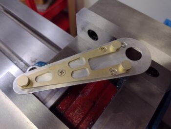
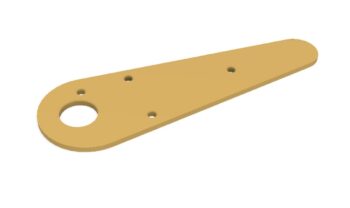
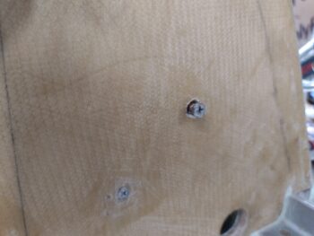
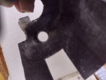
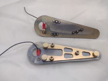
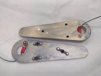
My next task was installing the three #6 nutplates on each nav light mounting backplate.  In addition I terminated a black ground wire and attached it to the backplate for each one as well.  These nav/strobe light mounting backplates are now ready to be installed into the wingtips and covered with a couple plies of BID.

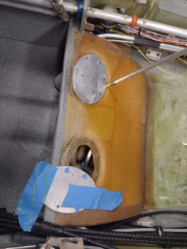
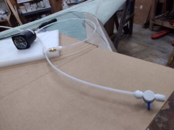
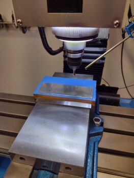
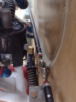
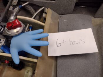
After the “15 hour” pic I took above, I then swapped my test kit over to perform a pressure check on the left fuel tank and thigh support tank.  I took extra measures to temporarily seal the thigh support top port cover, and I think it showed as I had far less leakage on the left tank than the right… at least in these tests.

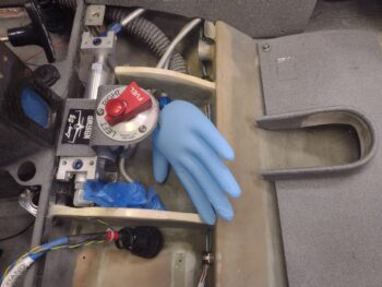
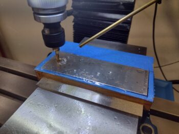
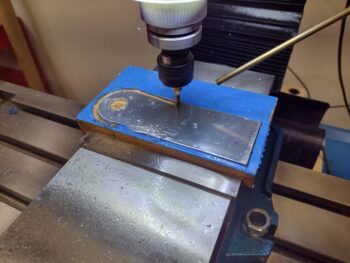
Here’s clearly a pic at 6 hours later.  I’m calling the left fuel and sump tanks good with virtually no deflation of the glove.  Still, I’ll leave it overnight and see how it looks in the morning.

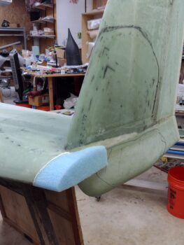
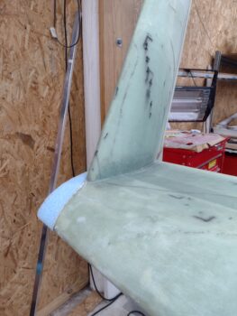
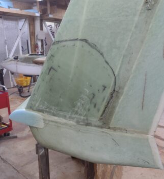
Since I trimmed my lower winglets down to about 2/3rds the size of the stock plans size —off the top of the foam core, not the bottom— they not surprisingly caused a bit more of a headache going on than the stock sized ones would have.

Why? Because by trimming off the top I reduced the overall width of the lower winglet mounting point a good bit… making them more difficult to align properly going on.  I attempted to focus on the trailing edge and align it straight with the rudder, but in doing so angled the bottom winglets out by about 1/8″ more than they should have been, all things being perfect (are they ever?!).

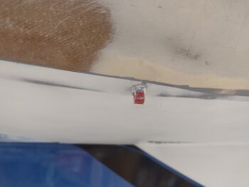
This slight “kick-out” didn’t manifest itself really until the wings were mounted and the plane upright.  Then you could see the bottom winglet a bit fatter than then top on the outboard side.  I used a straight edge to determine where the offending bulge was and marked it up… it had to be reduced to eliminate a need for extra micro to hide the bump and straighten up this slight difference between the two surfaces.

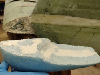
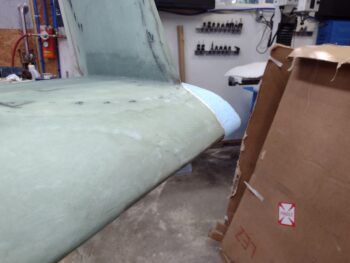
I grabbed my belt sander and went to town… it didn’t matter to me if I broke into foam, I needed to reduce this profile down significantly.

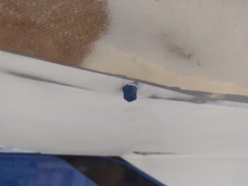
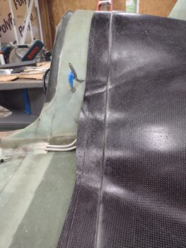
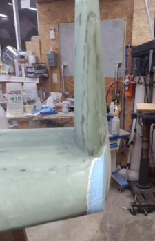
Surprisingly, I went 3 good rounds with the belt sander, rechecked and remarked the the surface protrusion each time, and then hit the areas again hard with 2 sessions of my 36 grit sanding board… and only on about 1 square inch on the right side did I hit foam.  I’ll patch that and assess this more when I get to finishing the winglets.  This bit of sanding did slim it down noticeably (see pic 2 below).

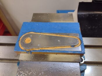
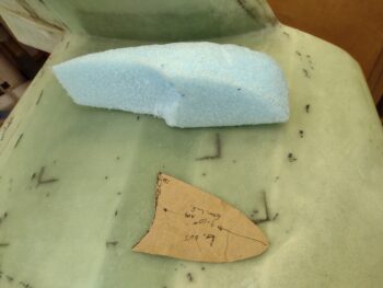
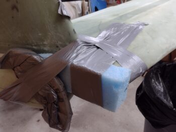
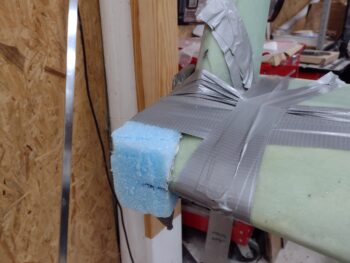
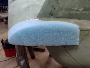
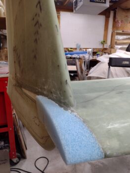
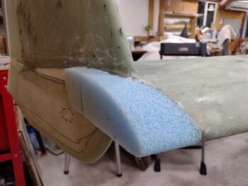
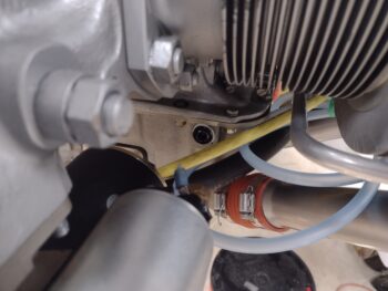
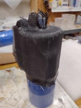
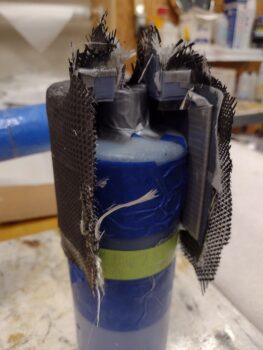
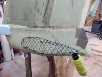
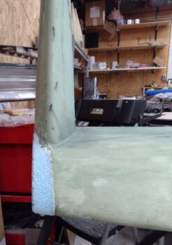
See the yellow string in the pics above and below?  I used that for my 90° perpendicular line to A/C centerline to then use a big square to mark the cut lines on the foam wingtip additions.  The resulting cut lines are pretty much parallel with the A/C centerline.

I then used a wood saw to cut the blue foam wingtip additions just outside the line.

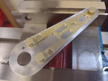
I grabbed my sanding blocks to then sand the blue foam away just up to the cut line.

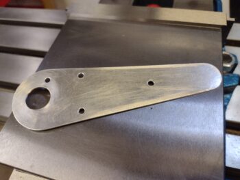
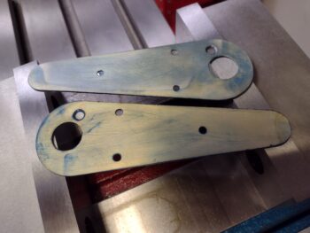
I did the same thing on the right wingtip… here are the pair of them shown together.

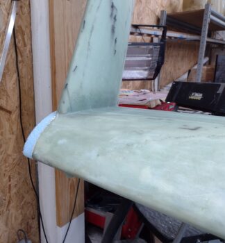
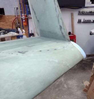
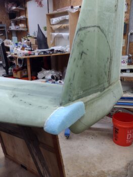
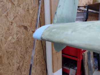
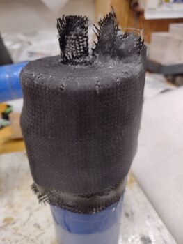
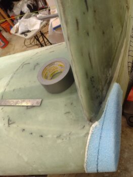
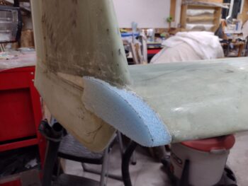
And a solo pic of the trimmed & sanded right wingtip.  Not bad.

Another shot of the trimmed/sanded right wingtip.  I like the way this looks, but I’ll admit that my biggest headscratcher now is how I’ll work the transition on the bottom winglet with this addition.

I’ll sleep on it and see if any ideas come to mind tomorrow.

I previously mentioned “perfection” and once again curiosity got the best of me.  I measured from the top aft winglet tip on each side to the front centerline of the nose.  Here are the results:
Right ↔ 266-3/4″
Left ↔ 266-5/8″
1/8″ difference for that entire distance?!  I’ll take it!!

Ok folks, calling it a night!

Chapter 20/21/22 – Lights ‘n leaks

Since a fuel tank pressure leak test typically is performed over a 24-hour period [although on further review I’ll note the plans state “several hours”], I wanted to get one going on the right fuel tank as quickly as possible and move on with other stuff.  I did spend a good hour cleaning off the wings and strakes which have been perfect long-term storage areas (ha!) but want things looking presentable since I want to do a video on this subject.  Something I’ve never seen.

Starting off, my plan to focus on only the fuel tanks for the pressure leak test was not going to happen.

In my mind I was going to cap off the GIB thigh support sump tank 1/2″ fuel inlet and 3/16″ vent line —both coming in from the main fuel tank— in the top outboard corner of each sump tank.  However, I failed to remember that I didn’t leave anything but a slight nub showing on these tubes entering into the sump tank.  And unless I had a very tiny stopper for the vent line AND could fumble around up in that corner to get it into place, I wasn’t confident the pressure wouldn’t just pop it out without tape or something securing it (focus inside the square mirror).

The scope of the Fuel Tank Pressure Leak Test now just became the Fuel Tank & Thigh Support Sump Tank Pressure Leak Test.  The only feasible solution without killing a bunch of valuable time was to put the lid back on the thigh support and hope that it doesn’t leak. I didn’t want to use any sealing goop (along with the gasket) because I’m not ready to go final just yet with the sump tanks.

In prep for the test I also pulled the protective plastic 1/8-NPT plug in the fuel drain and put in a Teflon-taped aluminum seal.

I’m using the same 0-15 PSI gauge device that Ary Glantz used when he tested his tanks, and I used a bicycle air pump to slowly pressurize the tank.

Although the tank gauge quickly fell back to zero, the glove was inflated so I went ahead and proceeded with simply watching the glove.  I could tell I had a very small leak with a minute amount of bubbling during my soapy water test at the very bottom edge of the thigh support cap [the pointer stick in pic above is pointing to area of initial bubbling during soapy water application].

The glove stayed inflated for about 2.5 hours but then was clearly well on its way to going deflated when I pulled the first test setup apart.

Test #2 was more old skool, but I was still keeping watching on the thigh support hatch cover.  I’m not sure if the water from my soapy water test had made the gasket act like a sponge, but I was getting zero bubbles after I tightened the screws up a bit more.

So I decided to go for another full test on round 2.  As you can see, this time I used an airspeed indicator and following Waiter’s instructions on IFlyEZ.com.  I filled the tank manually until 100 knots was indicating.

Over the first 10 minutes the ASI slowly dropped to about 90 knots, but then held that for about an hour.  Then over the next few hours it very slowly dropped.  I know that both the 0-15 gauge and ASIs lose air through slow leaks (as per Ary’s discovery) and so my main focus was the inflated blue glove.

Here’s the glove around 4 hours later.  By around 7 hours later it was essentially flat again.  Now, the shop did cool by around 3.5° F, but I feel that I have a very slow leak somewhere… and having literally doused every part of the system with soapy water. I’m not entirely unconvinced (having had soapy water in these tanks for multiple days without losing a drop) that it’s not something in my test setup.

That being said, over the next day or 3 I plan on A) testing the Left fuel tank/thigh support tank using these “standard” methods to see what I find, and B) most likely go with the “nuclear option” and employ Freon for testing for leaks.

After my initial fuel tank pressure testing was underway, I got busy machining a pair of mounting backplates for the AeroLEDs Pulsar nav/strobe wingtip lights.

I started by cutting out a 1.8″ x 5.4″ coupon of 0.04″ 6061 aluminum and secured it for machining with my new favorite method (and now tried and true!) of blue tape and super glue.

I then milled the left nav/strobe light mounting backplate…

And here it is about 10 minutes later…

It took me longer to clean it up than it did to machine the darn thing!

And a test fit for the external Pulsar nav light mount… like butta!

At this point I actually messed around a bit with the fuel tank pressure test, and also was using some OLD Alodine (again, that curiosity thing!) on the left nav light mounting backplate.

I then sliced another 1.8″ x 5.4″ coupon off the ‘ol sheet of 0.04″ thick 6061 and mounted it with blue tape and super glue as well.  Here I’m probing the corner of the sheet to set 0-0-0 for the X, Y and Z axes.

And then machined the right nav light mounting backplate as well.

And here it is… the right wingtip nav/strobe light mounting backplate, hot off the press!

I cleaned it up and also did a fit check with the Pulsar external mounting bracket.  Note the extra countersunk screw just above the front large hole: that is for an “airframe” (aka this mounting backplate) ground wire.

And here we have the pair of mounting backplates for the AeroLEDs Pulsar nav/strobe wingtip lights.  You’ll have to forgive the rather psychedelic appearance of these backplates given, again, that the Alodine I used was rather OLD!  Thank goodness these things will get buried in the wingtips eh?! <smile>

And with that, I called it a night!

Chapter 21/23 – Pipes & Wingtips

Curiosity got the best of me and I wanted to get some epoxy curing in some form or fashion on this bird, so I spent about 10 minutes shaping the blue foam wingtip cap for the left wing. Yesterday I rummaged around and found good foam scrap candidates for each wing tip, and today I’m getting at least one of them secured in place.

After cleaning some of the old dead micro and epoxy off the exposed foam at the leading edge area wingtip, I then slathered up both sides with micro.

After getting the foam in pert near the exact desired position, I taped the crap out of it to ensure it didn’t move and was pressed up tight against the wing tip and forward “corner” of the winglet (at the pointy junction where top and bottom winglets meet).

After my approximate half-hour diversionary task was complete, I jumped back on the left inboard exhaust pipe.  I cut the first wedge I had marked up from last night, set up the inboard in position again to mark round 2 of trimming.

Which is shown prepped here.  I then cut this slant wedge off as well.

After my first two rounds of trimming the intersection angle of the left inboard exhaust pipe, I then gave my exhaust pipe welding bubba, James, a call.  He let me know that he had 3 race car exhaust header sets he had to get out the door this week, but that next week he only had one… given that next week was looking like a light week for him, we scheduled my exhaust pipe weld-ups for then.  That schedule actually works out perfectly for me since I can get a jig built for the right side pipes to have James heat those up and bend them just a skooch (~1/4″) up.

With that, I finished round 3 of trimming the left inboard pipe intersection angle.

Since I now had some breathing room, I shaped the blue foam wingtip extension for the right wing and micro’d it in place as well.  And yes, I slathered it with duct tape again (which isn’t adhering so well… thus the added securing plies) to keep it in place tightly and securely.

By this point the left side wingtip foam addition micro had cured so I pulled the tape.  Looking good so far!

I then sanded the added blue foam block parallel to the surface of the wing… not bad!

Here’s another couple shots of the blue foam wingtip add-on shaped to match the left wing contour.  I’ll of course work the actual end shape A) after I decide exactly what style I want, and B) as I have time in-between the engine and cowling stuff.

I then took a break to grab a late lunch and finish my latest research (technically RE-research) on fuel tank leak testing.  I refreshed my knowledge base by looking at the plans, reading the CP newsletters, searching through the CSA articles, and looking at various canard build websites.

I decided for ease of getting the fuel tank pressure/leak testing done I would simply copy another smart guy builder, Ary Glantz, in his approach.  He used a small 0-15 psi gauge with an included schrader valve (for a standard bicycle tire pump) to pressurize his tank.  Moreover, they sell these gauges at Home Depot… the biggest problem being the closest Home Depot to me is 45 minutes away.

I tried to call Jess but she wasn’t available at that point.  10 minutes later I was back out in shop evaluating the left inboard exhaust pipe and marking it up for yet another round of trimming the intersection angle when she called me back.  I asked if she was up for having dinner in Jacksonville and doing some shopping while I wondered around Home Depot looking for all my tube fittings to cobble together a fuel tank pressure test kit.

An hour or so later we were having dinner and planning out our respective shopping adventures!

Upon returning back home with my new bag of goodies, I went back out to the shop for a bit to remove all the tape from the right wingtip new blue foam addition.  I then grabbed my sanding board and shaped the blue foam parallel to the wing curvature, just as I did on the left side.

Here are a couple more shots of the right wingtip foam extension from a lower angle.

I then closed up the shop and headed back into the house.  I had retrieved my box of AeroLEDs Pulsar Nav/Strobe lights earlier and I pulled the instructions out.  In the included instruction sheet is a template for the nav/strobe light mounting backplate.  However, the instruction sheet template is not to scale, and although they tell you how to print it out so that it is to scale, I simply spent 10-15 minutes modeling it up in F360 CAD.

I then 3D printed a test 0.020″ thick backplate to ensure it was correct and to scale, and Voila!  It was.

Within the next week I intend to construct the wingtip nav/strobe light mounting backplates out of 0.04″ thick 6061 aluminum… I’ll machine them so they are clean and to nice tight tolerances.

And with that, I called it a night.

Chapter 23 – Final pipe shape?

I had a lot going on starting out today, and most of it wasn’t in the shop until mid-afternoon rolled around.  Late last night and first thing today, I reviewed my initial plans for pressure testing the fuel tanks for leaks.  No, I haven’t done that yet and before I move into adding more glass and micro to the tanks, I want the leak tests completed.

I’ll remind everyone that between my old hangar getting hit by a tornado, and thus destroying a lot of my historical note binders with water and wind, combined with Windows 7 no longer being supported so my instant access to One-Notes ended (I can go through a painful, convoluted process to get them… and some I’ve retrieved).  After these two events, my “instant info” access & retrieval was hampered greatly.

I note the above to explain why I spent a good half hour going through all my emails in performing some engine baffle data collection and consolidating pics, etc. into a PowerPoint presentation.  Yep, engine baffles are looming on the horizon!

In addition… since I haven’t capped the end of my wings or made provisions to mount the nav/strobe lights yet, I did a bit of the same data collection thing.  Only this time reviewing pics online and my own site in a somewhat impromptu design review.  I had a number of pics of my buddy Marco’s wingtips for his bird JT, but didn’t have any I could find for Mike Beasley’s “Scooter”… I texted Mike and thankfully he was at his hangar so within short order I had over a half dozen pics of his wing tip/nav light/winglet interface.  I’ll note I also did a good once over of Dave Berenholtz’s site as well, and hit up fellow builder Brian Ashton in Alaska for what he had for his configuration.

I then got out to the shop.

The first thing I did was set up my welding station: got the TIG welder all set up and plugged in, and then test welded some scraps of this 321 stainless steel pipe.  As per Clinton at Custom Aircraft Parts, 321 SS requires ER347 filler rod and I don’t have any on hand… nor does any welding shop in Eastern Carolina! (actually within an hour of me…).  Moreover, the cost of getting it shipped to me here within the next week wouldn’t be worth the money (not even Amazon has a vendor that can ship it within 2-3 days).

This 347 welding rod is important since my test runs at tack welding such thin-walled pipe was not working and serving only to melt the edges of the pipe segments being joined, no matter what amp setting I was using.

Thus I decided that I would simply mark the pipe configurations and take all the pieces to James and have him weld them up from individual pieces.

With my 321 stainless steel exhaust pipe welding stint cut tragically short, I proceeded to pick up where I left off last night in shaping the intersection of the new straight segment on the left inboard pipe.  After the initial slant cut to interface it with the 90° elbow of the slip joint mount tube, I realized that my 2.2″ extension piece of pipe was just a hair short and wasn’t going to pass muster.

I grabbed the outboard pipe, marked off 2.75″ inches (it came out to 2.7″ after cutting), taped the cut line and trimmed it down.

I then added the 2.7″ extension to the inboard pipe and prepped it for shaping to intersect (again) the 90° elbow of the slip joint mount tube.  It was early evening at this point and I had told Jess, who unexpectedly had the evening off, that we could go out for a bit and enjoy a “cool” mid-80’s (vs the recent mid-90s) evening.  Thus again, this task will be continued tomorrow.

I’ll add that I forgot to post this yesterday: the newly arrived brass 1/2-NPT 45° street elbow for the bottom engine sump oil heat OUT hose… to replace the current steel 90° one that is just way too big and reeking havoc with its zero clearance with the SCEET tubing.  Just as with the sniffle valve, I’m hoping a switch to a 45° street elbow will solve my clearance issues.

Again, I am seriously hoping and cautiously optimistic that my exhaust pipe clearance issues will be resolved soon!

Chapter 23 – Left pipes a tweakn’

Today I continued on in my quest to get the exhaust pipes tweaked to fit inside the cowling… and still working specifically the left side at this point.

Before I could continue on with finalizing the configuration of the left side exhaust pipes, I needed to check the clearance between the spark plug in cylinder #1 with cylinder #3’s exhaust pipe.

I had Champion aircraft spark plugs installed but after a good bit of research during the past year I learned that Autolite 386 plugs are good to use with the PMag, so I picked a few up.  Now I need to install them in the bottom plug holes in each cylinder to test out clearance with both the actual plugs I’ll be using and the PMag spark plug cables.

Now, not only are these Autolite 386 spark plugs 18mm [read: no adapter] and run well (according to a bunch of RV drivers… but can we trust them?? ha!), but they are pretty darn cheap to boot.  That means I will be changing them out at every annual… which is where this exhaust pipe story has even yet another twist….

You see, I thought the tight cowling was causing all the issues, but interestingly enough when I went to remove the aircraft plugs on the right side, I couldn’t even get the socket over the plugs due to the exhaust spring tabs and springs being in the way.  With some judicious bending of the forward cylinder’s exhaust tab I could force the socket on there and got the A/C plug removed.  And yes, the Autolite plug was easier going in.

However, on the aft cylinder I had to remove the exhaust pipe completely to get my socket onto the A/C spark plug to remove it.  I had a decent bit of oil oozing out of these cylinders, so I wasn’t mindful of replacing the aft cylinder exhaust pipe first to test out if the Autolite would have gone in easier than the A/C plug coming out.

I then took a few minutes to connect the PMag spark plug cables up to each respective plug and run all the cables forward to the front of the engine.

Ok, back to the exhaust pipes.

I had marked the left outboard exhaust pipe to allow me to secure the pipe to the 90° mounting flange, according to my index mark.  After mounting all the pipes in place I then put the cowling back on.

Here’s the left outboard exhaust close to the configuration where I plan to tack weld it in situ, and then have James finalize the job with a beautiful TIG weld worthy of 321 stainless steel!

I then of course checked the clearance of the installed bottom spark plugs and their associated cables… much better than I had expected and not bad at all (I put green tape on the black spark plug cable boot to make it more visible).

And here’s a shot of the clearance between the left outboard exhaust pipe and lower cowling.  Optimized?  Hell no!!  But good enough for the space I have going on here!  Especially since I’ll be lining the interior cowling with Thermo-Tec to keep it from burning up (as if I had a choice!)… I’ll also most likely get the pipes ceramic coated as well fairly early on to cut radiated heat down as much as possible.

I then turned my attention to the inboard left exhaust pipe.  Here’s the “dip” issue I pointed out yesterday. I used a ruler to show the dip more clearly.

And here’s somewhat the same thing over on the bench… note the dip is very close to 1/4″ deep.   Which is significant in this situation.

Back to the left inboard pipe set in place, here you can see that dip coming down and kissing the bottom cowling.  Now, in reality that pipe is not touching the cowling.  The issue is without a pipe used to lever over the spring loaded slip joint mount, it springs outboard a bit and messes up the mocking up of the pipe… so if it were all put together there would actually be daylight (albeit not much) under that dipped pipe.

I took measurements at the point where the forward curve (that causes the dip) starts on the left inboard exhaust pipe.  I then set it in place and determined as best as I could the length of pipe (after trimming) that I would need to not only connect the pipe back into place, but to also ensure it stays nested with the outboard pipe.

My measurement was close to 1.8″ to remove the dip, so I planned on cutting off a 2.2″ replacement straight segment from the very aft end (which is excess and will get trimmed off all the pipes). The 0.4″ added difference as extra just in case [in retrospect it may still not be enough].  I then marked each cut line at each end with green tape.

I then spent some time with my Dremel and small cut off tool to cut the pipe at the cut lines.  I didn’t spend a lot of time on the green tape end since that will get trimmed to reconnect to the 90° pipe.

I then set it back in place… this isn’t a perfect representation since the added pipe is still a little high, but the low point now will be the 90° elbow and not the dip.

Moreover, with the hole in the cowl from me removing the goiter that was there for the alternator, I plan to expand my fill out a bit wider to add a hair more clearance depth to encompass that area of the low 90° elbow.

Here’s another shot of the left exhaust pipes mocked up in place.  Note how you can now clearly see daylight underneath the majority of the pipes.

Another shot of the left exhaust pipes… I’m going to do my darnedest to keep the pipes nested together to optimize their flow.

Again, although set just a tad high, here is a good representation of the now straight inboard left exhaust pipe… sans dip.  Much better as we can see above regarding clearance with the cowling.

Tomorrow I plan to break out the TIG welder and do some tacking on these pipes.  After I lock in the position of the left outboard exhaust pipe then I’ll configure the inboard pipe and tack it up as well.  Once the left side pipes are actually welded up and in place, then I’ll work the comparatively minor tweaks on the right pipes.


Chapter 23 – Pipes… mind the gap!

Today was all about getting the left exhaust pipes configured in situ.

I started off with the left inboard exhaust pipe and marked its cut line with the green tape.

I then made my initial cut on the left inboard exhaust pipe.

With a 1/2″ spacer in place for minimum clearance you can see the resulting gap between the 2 pipe segments.

I trimmed the forward 90° segment about 1/8″ on the bottom and about 1/4″ off the top. This trimmed 1/8″ on the bottom reduced the depth of the pipe by about 0.070″ (from the very lowest point).  This gives me a minute bit more clearance with the cowling, but I’ll take every bit I can.  The differential amounts removed served to angle the opening up just slightly.

The green tape is the next round of trimming for the aft segment of the left inboard exhaust pipe.  You can see it will bring the joint much more closely aligned…

Although the new cut didn’t make for a perfect connection angle… I’m “walking” these joints in so as to not overshoot the required angles.

[Note the curved “dip” of the first ~2 inches of the aft pipe segment? (right after the cut) Although this rounds out the flow and makes for a nicer curve, it also drops the pipe to the closest point of all the exhaust pipes in relationship to the cowling surface… I’m thinking strongly of removing this curved section and replacing it with a straight segment of the same length]

A bit wider view on the left inboard exhaust pipe.

Although I marked the left outboard exhaust pipe cut line with tape along with the inboard pipe, I didn’t want to convolute the information flow above…  in reality I cut the inboard pipe first, then the outboard pipe, before fine tuning the inboard pipe.

As I was pondering the forward curved 2-inch section of the inboard pipe I mentioned above, I cleaned up the cuts of the outboard exhaust pipe and then mounted the outboard exhaust pipe 90° section.

I then taped the left outboard pipe in place with spacers for elevation and cowling clearance.  After some long pondering on this outboard pipe as well, I decided that I will most likely shape the (currently cut) weld joint to pivot the pipe in a clockwise manner (looking towards nose) to gain a bit more cowling clearance and also more clearance for the #1 cylinder spark plug (the clearance is too close for comfort at this point).

In addition, the aft end of the pipe will have to come up about a 1/4″ higher to facilitate the clearances above.

Here’s a couple shots of the “nested” left side exhaust pipes… definitely an improvement from what they were! (but we can do better….!).

And a look at the right side pipes.

Admittedly, these shots are a hair misleading because the wood spacers are both lifting the longer pipes UP while also pushing the flange of the lower cowling DOWN just a bit.  In reality, these right-side pipes will both most likely need to come up about 1/4 to 3/8″.  The bend, whether an actual bend or cut/reweld will be a few inches aft of the corner of cylinder #2.

And here’s one last shot of both left and right pairs of exhaust pipes in their newly elevated states.  Yes, it’s a work in progress folks!

My plan is to work these exhaust pipe configurations over the weekend and have them done by next Monday/Tuesday.  Then as soon as James has time, I can get these things welded up and get on with the upper cowling install.

I will note that there may be more welding required on the aft ends of the pipes if they need to be turned downwards to be leveled out on a more horizontal plane… just a thought at this point.

Pressing forward!

Chapter 23 – Engine tidbit checks

With the engine back on the plane, I started off this morning by placing the top cowling in place and weighing down the corners to keep it pinned in place.

On the aft end I have the top cowling literally resting on the flywheel, so we know it’s as low as it can go for this test . . .

I then grabbed a shot of the newly installed 10.57″ long oil level tube with the dipstick cap mounted in the top.  As you can see, plenty of clearance with the cowling set in pretty much the lowest possible position… although this clearance is in line with my calculated measurements, I’m always very happy to see it confirmed in a real world fit check.

I’ll remind ya’ll that Mike M. made these cowlings to fit around an O-360, so there is a scooch more room (theoretically… not on the bottom side with my engine eh?).  Again, I’m very glad to see this new dipstick setup fitting nicely into the scheme of things.

Before pressing forward with my other tasks, I refreshed the desiccant in the top spark plug contraptions… this hot humid weather is burning through my desiccant!

In prep for installing the oil heat system oil pan feed fitting to dial in the standpipe collector flow, I did a quick check on the new dipstick length.  Since the new oil level tube is 4.2″ taller than the old one, I simply added 4.2″ to the raw stock 3/16″ dia. 6061 rod that will be my new dipstick.  I drew a Sharpie reference line at the top of the dipstick cap to keep track of the dipstick length.

Well, the dipstick bottomed out inside the engine and pushed the dipstick up about a 1/4″ when the cap was threaded all the way in.  My goal is to have just the end of the dipstick touching the top surface of the oil with 2 quarts in, and I wanted this ready to go when I added oil for the oil heat standpipe check.

I then removed the bottom plug from the oil pan where the oil heat standpipe fitting gets installed.  As the little bit of oil drained out, I gathered up the oil heat standpipe fitting and my tools in prep for installing it.  Since this is just a temp install, I used Teflon tape to keep the oil from leaking around the fitting.

I then installed the fitting into the bottom of the engine pan. Notice how massive this -8 90° elbow fitting is… unfortunately this sucker is too big and intrudes into the space of the air induction SCEET (orange) tubing.   More on that in a bit.

Back to the oil heat standpipe oil flow test.  I don’t even remember how or why at this point, but I know I calculated the height of the standpipe at 4.4″ to give me somewhere between 2.5 to 3 quarts of engine oil in the bottom of the oil pan before it starts flowing into the standpipe for the oil heat system.

This is obviously a failsafe to keep a leak in the oil heat system from causing a catastrophic engine failure due to engine oil depletion.  Lycomings are happy enough on 2.5-3 quarts of oil, thus my calculation.

Well, all these many years later I have to say I nailed it!  At 2.75 quarts in the oil started flowing out of the oil heat fitting.  I confirmed this by measuring the collected oil after putting 3 full quarts of oil into the engine, and the oil that flowed out was almost exactly 0.25 of a quart.

The issue now (I have to say, at this point I’m not surprised!) is of course the underside clearance between the oil heat fitting and the SCEET induction tube.  The induction tube is not moving, so that means I need a new solution for this oil heat fitting.

So just as I did with the Sniffle Valve, I ordered a 1/2-NPT brass street elbow and a length of brass tubing.  Since I now have a confirmed length on the required height of the heating oil collection standpipe, I can braze a brass tube to the street elbow and hopefully get the clearance required betwixt oil heat fitting and SCEET tube.

I then ran down to Harbor Freight and Lowe’s to grab some tools and materials I needed (in part) to install the oil plug on the aft side of the engine oil pan.  I will say that I had a steel plug here to replace the one that came out, but after reading an entry by Klaus on a W&B thread in the COBA forum, I have to say I was re-motivated to trim as much weight off as possible on this bird.

So I ordered some more aluminum fittings, including this plug, to save a bunch of ounces in the engine compartment.

In fact, also due to that forum post I recently went around weighing all my new/latest stuff and re-tweaking my overall estimated weight.  With the addition of an O2 system (5+ lbs), the near-doubling of my estimated upholstery weight (13 to 25+ lbs), rounding up my estimated paint weight another 8 lbs, and including both the RAM air scoop and aft nose/avionics cover weights… I’m at 1050 lbs.  Remember, this includes the weight for the oil heat system as well and literally every single component going in the plane, plus a 10-pound padding just in case I missed something.

Tomorrow I plan on remounting the exhaust pipes and the lower cowling, and then cutting the exhaust pipes to fit the lower (and upper) cowling.

Chapter 23 – Exhaust Pipe Tweak Plan

Today was all about finishing up a bunch of tidbit tasks to allow me to remount the engine to the fuselage.

The underlying reason my timeline for remounting the engine was hastened is in regards to my exhaust pipes.  After communicating with Clinton at Custom Aircraft Parts and sending him detailed pics, including ones of the left pipes’ immobilization, he told me that he was ready for me to send the pipes to him to get tweaked… one at a time.  Which makes sense since we’re doing this configuration tweaking remotely.

To be certain, after months of communicating on this back and forth, I am very appreciative that Clinton was going to do what he could to resolve these clearance issues.

However, Clinton’s caveat was that their current lead time on projects was 45-60 days. I totally understand shops being swamped with business, which is a good thing, but if we work these pipes one at a time, with the cost and time of shipping back and forth, this could be a rather costly endeavor that could potentially take 6-7 months longer.  That timeline is a No-Go for me… so I had to find another way.

Enter local race car header builder James R. … through talking to one person after the next, who knew this guy, etc. I finally got James on the horn.  His shop specializes in high end stainless steel exhaust systems for race cars, and he understands exacting tolerances… and more importantly: stainless steel.  No disrespect intended, but unlike Clinton and gang who do aircraft exhausts as their bread and butter, James seems to be looking forward to a slightly different challenge and helping out on something that is unique to his world.  Moreover, he’s 45 minutes away!

So here’s the plan: I am going to cut and set the pipes in place in-situ on my bird, tack weld them and then simply take them to James to have him weld one weld on each pipe and call it a day.  To be clear, in January I spent weeks looking for a “James” in the local area and nobody knew anybody who had the high level of knowledge and experience that I was looking for… I guess round 2 of my search proved more successful.

Bottom line is I’m pressing forward, and am cautiously optimistic that within the next 2-3 weeks this exhaust pipe clearance issue will be a thing of the past.

Ok, back to the current build.  I started off by digging a hex-shaped divot into the firewall to mount a bolt/screw to allow securing an Adel clamp inside the GIB headrest engine components compartment.  I floxed in the bolt, secured it on the other side and added a ply of BID over the bolt head.  And then peel plied it.

In assessing the “completed” fuel pump cooling shroud, there were 2 things I wanted to tweak.  Both involved the air inlet nozzle.  First, the CF at the joint between nozzle and body wasn’t as smooth as I wanted.  Which I could have just used some micro to clean that up.

But second, although the 2 plies of CF for the nozzle seemed stiff enough, since I was going to be applying clamping pressure to secure the SCAT tubing to the nozzle, I really wanted a 3rd, internal ply, of CF.  So I laid one up on the inside of the nozzle tube, which transitioned over the nozzle-to-body intersection as it overlapped onto the inside of the cooling shroud.  I then peel plied this internal CF layup.

Here’s what that looked like after I pulled the peel ply and cleaned up the layup a few hours later.

While that last CF layup was curing, I also epoxy wiped the fuel pump cooling shroud with 2 rounds of West epoxy.

The epoxy wipes were simply to fill in any pinholes, etc. on the surface of the shroud.  When I remove the engine next time I plan on wet sanding the excess epoxy off and either leave that if it looks fine, or maybe hit it with one final thin epoxy wipe or a coat of clear coat.

I’ll note that in its current state this fuel pump cooling shroud weighs in at a whopping 1.9 oz.

I also evaluated the SCAT tubing flow, both locally to the fuel pump cooling shroud and as part of the entire system beginning at the RAM air scoop-located NACA scoop.  I added an Adel clamp to secure this segment of the of the SCAT tubing near the cooling shroud.

I also installed a Clickbond on the firewall for another Adel clamp to secure the SCAT tubing coming up from the NACA scoop.

I am mentally creating the “Y” joint that will attach this SCAT tubing to the pair of 7/8″ diameter SCAT tubes that go to the fuel pump and PMag for cooling (I actually laid up and peel plied a 1.5″ ply of BID on the end of the aluminum tube that will get attached inside this SCAT tubing and have the “Y” tubes attached to it… not shown).

I had printed out wire heat shrink labels a long time ago when working on the P9 and P10 firewall electrical connectors, and I finally heat shrank those 5 labels onto the wires tonight.

I also remembered that my Oil Temp sensor was installed only hand tight, so after some quick research on that I installed it to its “torque” spec (actually rotation spec on this guy: 135° after hand tight to properly seat the crush ring).

I then safety wired both the OT sensor plug and the cover cap on the mechanical tach port (top center of pic, in-between the white oil filter and orange SD-8 b/u alternator).

I had planned on Jess helping me with remounting the engine, but she got tied up a bit helping her grandmother so I pressed forward on my own.  I figured since I may have to do it someday on my own anyway that this would be a good test of my abilities.

With the engine mount extrusions exactly the same distance apart as the engine mount nubs, I found the trick is to bring the engine down a hair low, angle it so the front is higher than the aft side and “hook” the lower nubs into the lower engine mounting extrusions.  Then with constant forward pressure on the engine, raise it up and seat the top nubs onto the upper extrusions.

That worked a treat and I really had the engine on and initially secured in about 15 minutes.  Add another 15 minutes to secure the hardware and I was done with the install.

I then checked the clearance between the fuel pump overflow fitting and the aileron torque tubes… a good 1/4″!  Again, that equates to a mile in Long-EZ specs! <wink>.

The same is true for the oil hoses, as I’m very happy with the clearance between those and the firewall as well.  These are the last items I need to be concerned about clearance-wise between engine and firewall… hoo-yah!

Tomorrow I plan on getting to work on the exhaust pipes and hopefully get those clearance issues taken care of ASAP.  As for now, Jess is making Keto-friendly tacos… time to sign off!

Chapter 23 – Fuel pump cooling done!

After a good overnight cure I pulled the CF/BID and its plug off the canopy sealing goop bottle…  I then trimmed all the edges of the layup to clean it up.

I then pulled the fuel pump cooling shroud off the plug…

And pulled the inside peel ply to go a few rounds in creating the slots for the fuel IN, fuel OUT and overflow fitting bosses.  I’ll note that this is another area where my roll-your-own design is different from Lycoming’s cooling shroud: theirs has holes that require the shroud to be mounted prior to connecting up all the hoses/fittings.

Here we have the last of the iterative test fits with the final trimming of the 3 slots complete.

I then did some test runs of the 7/8″ diameter SCAT tubing to figure out where the optimum placement for the tube attach nozzle should be on the cooling shroud.

I had thought about coming in at a lower angle, but here I figured I should follow Lycoming’s lead with the air blasting at and pointing towards the main body of the pump: to optimize the effect of the cooling air flow.  This required more of a 45° down entry into the cooling shroud… I’ll again point out that my tubing nozzle is about 180° out (port side) from Lycoming’s (starboard).

I used a length of thin-walled plastic pipe that I picked up in Germany for the plug to create the tubing nozzle.  For the hole I simply drilled a pilot hole then used a 7/8″ diameter hole saw.

Before glassing up the nozzle, I made a slit down the length of the plastic pipe so I could collapse it for removal after the tubing nozzle cured.  I then covered it with clear tape and peel ply before laying up 2 plies of carbon fiber.  I of course completed the layup with more peel ply.

Here is the nozzle trimmed about 4 hours later, with the fuel pump cooling shroud back on the fuel pump.

I then threw my SCAT tubing on the nozzle for a quick check and to show the configuration of my fuel pump cooling setup.

And with that, I called it a night.

Chapter 23 – Fuel pump shroud glassed

I started off this morning by sanding the interfacing surfaces of the fuel pump cooling shroud layup plug before using some super glue and clamps to secure them together.

The tabs up top are all about securing the cooling shroud in place.  If you’ve seen the Lycoming shroud it has holes that go around (or under?) the fuel pump main mounting bolts.

Not wanting to mess with removing the bolts and re-safety wiring anything, let alone the fact that the Lycoming shroud is metal and I don’t want to have my fuel pump secured in place with a layer of composite in between, I chose to simply “surface” mount this thing.

I’ll do this by glassing in strong magnets upright in the back tabs to help secure the shroud to the fuel pump mounting bolt faces.  Then I’ll RTV the interior tabs to each side of the riser on the top middle of the pump.

It took a decent bit to tape up the plug… here it is in all its splendor.

I was using fast hardener in my MGS epoxy, and with the outside weather over 100° F I didn’t realize that the much “cooler” feeling shop was still nearly 80° F.  Thankfully I didn’t mix up much at first since I started with an internal application of peel ply over the tape.

I really hate wasting expensive composite materials, so the first ply of BID
[again, only because this shroud will be directly touching the aluminum body of the fuel pump… I don’t want any galvanic reactions going on between the CF & aluminum in a place I can’t easily inspect without pulling the engine off]
was 4 pieces of scraps, followed by the first layer of CF which was another cobbling together of scraps, followed by a single ply of CF.

As I was laying up my first ply of BID my cup of epoxy exothermed.  That’s when I found the thermometer that the rascally squirrels (they’re a total PITA!) had knocked over.  Ahh, it was much warmer than I thought in the shop.  It actually happened a bit later as well when I had barely any epoxy in the bottom of my cup, being pretty much done with the layup.

I did actually peel ply the layup after I finished, but didn’t grab a pic of it.  I had some friends that needed to borrow my trailer in a bit of a rush, so I was trying to get this thing knocked out in general, but to help them as well.

I finished the layup in late afternoon and then made some phone calls regarding the exhaust pipes.  I then got cleaned up and headed downtown to take Jess out to dinner… don’t want her feeling like a Long-EZ build widow!

I pulled the peel ply and grabbed these pics you see here after returning from dinner.

Tomorrow I’ll pull the plug off the bottle of canopy protective goop (that I never used… glad I got some use out of it!) and then trim it up.  Clearly after a trim and some judicious sanding it will look much more presentable!

Pressing forward.