Chapter 22/24 – What…more sanding?!

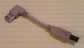
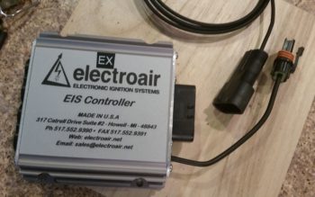
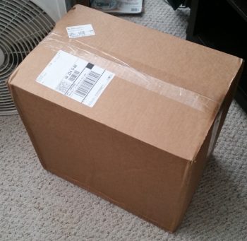
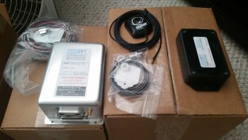
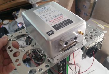
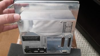
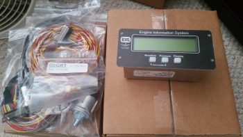
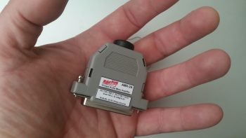
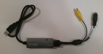
I started off today receiving the package from GRT with the USB video module that I discussed in yesterday’s blog.  I looked it over a bit and noted how lightweight it is.

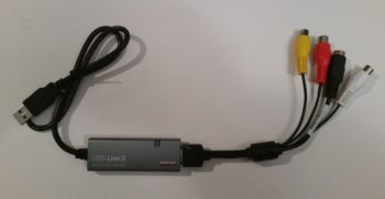
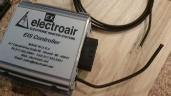
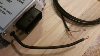
I then made it even a little lighter by summarily lopping off the left & right audio feed jacks since I know I won’t be using them in my configuration.

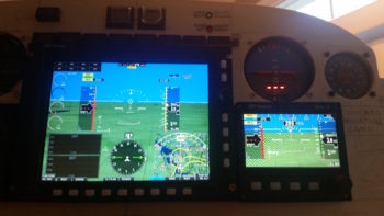
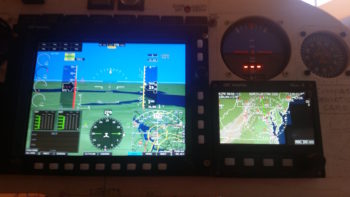
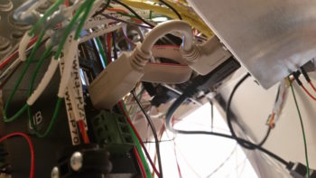
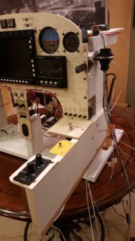
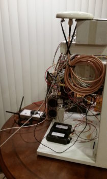
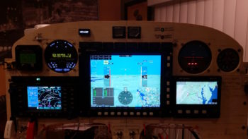
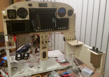
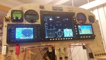
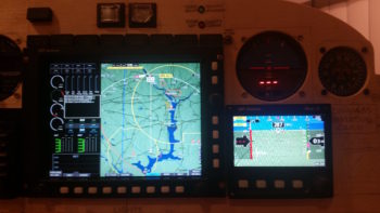
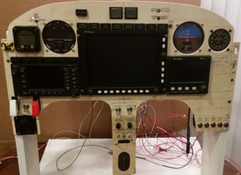
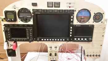
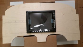
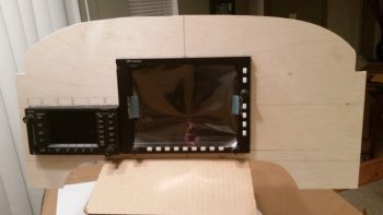
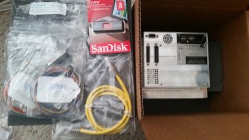
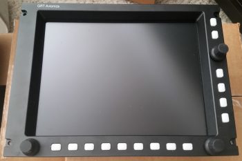
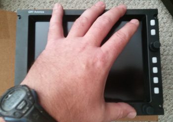
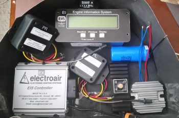
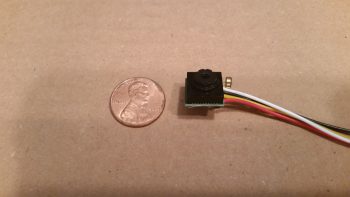
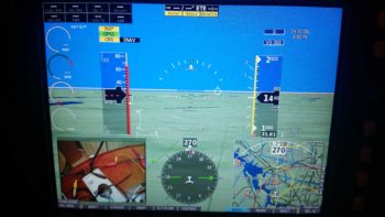
Of course I couldn’t resist trying it out, so I hooked it up to my 4-port USB hub, connected the camera and then fired up the panel. Within 2 pushes of a button I had the inset showing what the camera was viewing.  Awesome!  Especially since there was no software configuring or loading required.

Within the next few days I should good a manual video channel switcher normally used by gamers that I got for a few bucks off of Ebay.  I’ll use that for some testing and report the data back to the guys developing the video auto-switching module on the AeroElectric Connection forum.

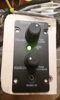
A sideline benefit to firing up the panel and checking out the new video capability was that I also got to power up the Dynon Intercom for the first time.  Now, I didn’t do anything with it to test it out, but I didn’t see any sparks, flames or smoke, so I’m going to call it good for now!

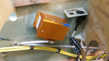
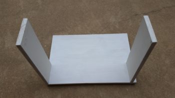
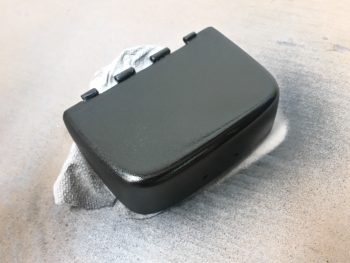
I then went to the shop and spent well over an hour dialing in the left armrest, focusing on its fit & interface with both the heating switch panel and, yes, the cupholder.  After getting the fit as close as I could, I decided that I needed to lock it into position by installing some mounting brackets –4 out of the 5 identified mounting bracket positions so far– to keep this thing from going all willy nilly on one end while I’m trying to do something on the other end.

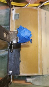
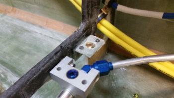
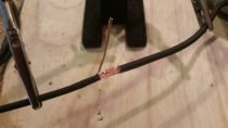
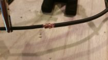
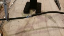
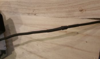
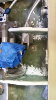
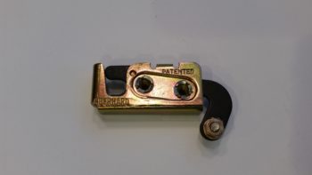
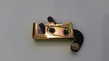
Before I got deep into the armrest mounting though, I only had less than a couple of hours to make a lot of noise (I live in a townhouse with a STRICT homeowners’ associate that has a tizzy if I make noise after 10 pm).  One of those noisemaking tasks was to trim back the Nylaflow, glass and micro about 4″ so that I could mount the parking brake handle farther forward at the left side base of the nose wheel cover (NB).

I originally planned to have the parking brake handle installed adjacent to the nose wheel viewing window on the left side of the center panel strut, and the nose hatch release T-handle on the right side.  After assessing it for a while, I wanted it farther forward to get it out of the way during flight ops, and plus I wanted to make it so that I had to unbuckle my shoulder harness and lean forward to get to the handle…. which of course leaning forward is infinitely easier to do in a Long-EZ with the canopy open.  So, in short I’m saying that for both T-handles I wanted to ensure it was no-kidding ground ops thing.

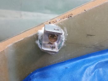
After making a bunch of noise by ensuring that I could move the parking brake handle conduit, I then made a bit more when I trimmed the cable sheath on the parking brake cable assembly with the Dremel tool.  I cut a piece each of angled aluminum and 7-layer glass bracket stock for 2 more mounting brackets for the left armrest.

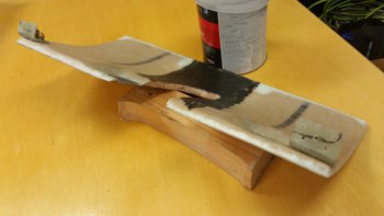
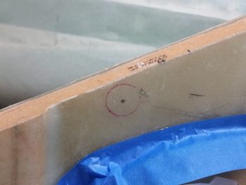
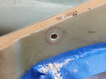
I then started making quite a bit less noise by simply using the drill to finalize the mounting brackets for the left armrest.  I made up one bracket for a #10 screw, and the other a bit smaller for a #6 screw.

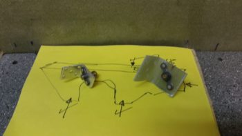
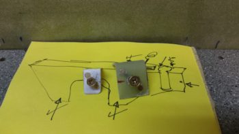
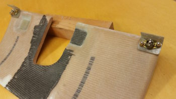
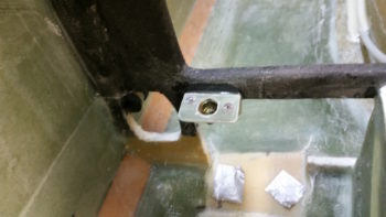
I then prepped the left armrest by taping up the edges in the immediate area of the mounting brackets, and then attaching the brackets in place.

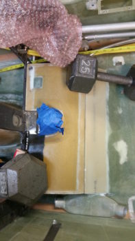
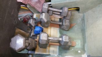
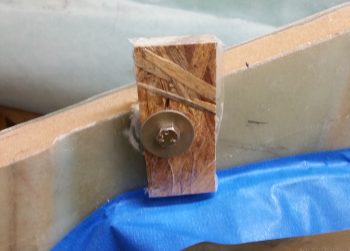
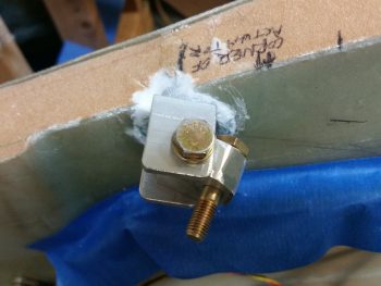
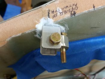
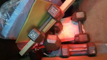
I then whipped up some flox using fast hardener and floxed the left armrest mounting brackets into place.  Although just about each one needed some type of persuasion with a heavy dumbbell to keep it in place.

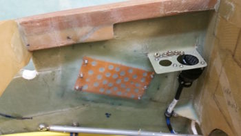
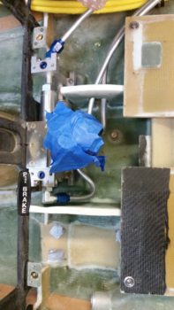
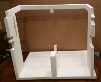
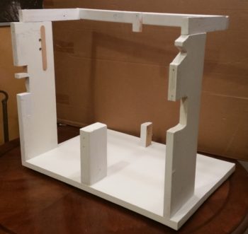
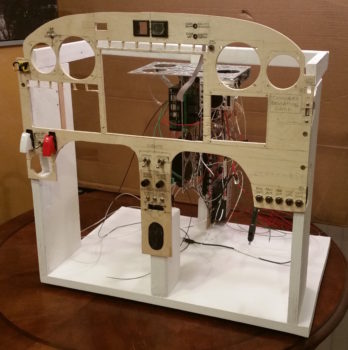
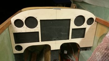
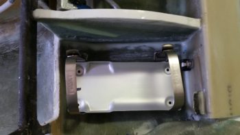
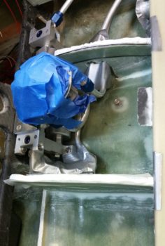
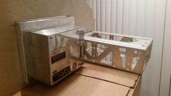
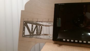
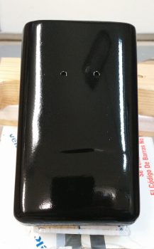
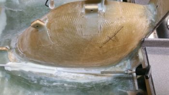
Also, to be clear, I have a few more mounting brackets I’ll need to install on the left armrest, this is just round #1.  [BTW, the left armrest is at the very bottom of the pic, seat bulkhead is on right side]

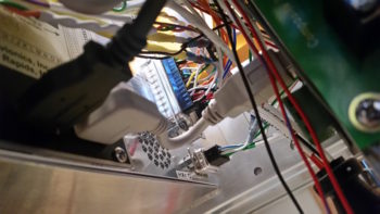
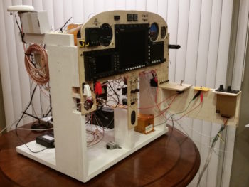
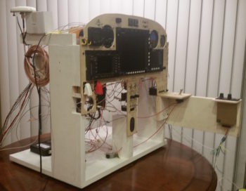
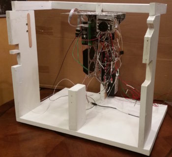
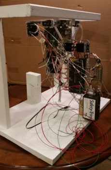
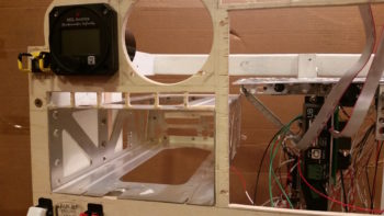
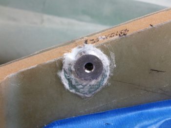
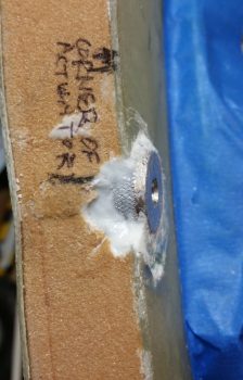
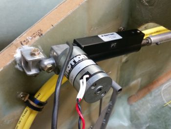
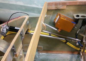
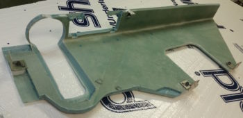
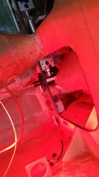
Here’s a shot of the wheel well cover (top left) and front side of the panel.  I have the heat lamp shining primarily on the left armrest’s very forward mounting bracket that is attached to the aft side of the lower left instrument panel (lower right corner of pic).  Since I had some leftover flox, I very quickly finished prepping a small bracket I had cut from the 7-layer glass bracket stock I made a while back for the thigh support CAMLOC fasteners.  I then floxed it in place on NB (middle left of pic) for use in securing the parking brake handle.

Tomorrow I’m meeting some friends for lunch over in Maryland, so it will probably be a bit shorter build day.  But I will try to knock out as much as I can.


Chapter 22/24 – Coming together…

I started out today by doing a bit of electrical system administrivia until I could call GRT Avionics.  I then called them and left a voicemail detailing my tale of woe regarding the AHRS not talking to the HXr EFIS.  Within 15 minutes Mark from GRT called me back and within a minute I had the AHRS online.  It was simply a matter of setting the baud rate to 19200 (which I couldn’t find in the documentation) and it was off to the races from there.

While I had Mark on the phone we also worked through how to set & label some of the analog ports for my specific inputs such as the GIB thigh support fuel sump low fuel alarm. He had to do some digging around but he found the info that allowed me to set all my unique analog port inputs.

Here’s another shot with some slightly different screen views than above.

Upon checking my mail I found that I had received the 4″ USB dongle I ordered to connect the HXr EFIS display to the 4-port USB hub.  The USB hub connects items such as the Radenna SkyRadar ADS-B IN Receiver and by adding a little nub of a USB device also provides Bluetooth capability for the GRT EFIS system.  Specifically, with a small Android tablet the GIB will be able to see essentially the same info on the PFD as I do up front.

I then installed the USB dongle . . . this is the HXr EFIS side

And here is the 4-port USB hub side.  You can see there is not a lot space behind (again, technically “in front of”) the EFIS display unit.

I also received the parts from ACS that I was remiss in ordering in a timely fashion.  With the #2 CAMLOC receptacle in hand I then pressed forward with the pilot thigh support cover CAMLOC locking tabs installation.  Two items worthy of note on these CAMLOC tabs is that, first, I realized I did not have countersunk rivets large enough to mount the CAMLOC receptacles to the tabs…. hmmm?  I quickly determined that a #6 countersunk screw would do the trick so I rounded up some of those (I only had the fancy SS hex drive #6 screws that would work) and some locknuts and got to work.

The second issue was that the left tab would not sit flush with the lower instrument panel cross piece and that it really required some force to get the thigh support cover to seat down in its proper position.  Of course I didn’t notice this until the receptacles were mounted in place and the CAMLOCs were installed tightly.  I fiddled around with it for a bit and realized it just wouldn’t work with the bracket at a 90° angle since it was obvious the angle must be more acute.  I don’t really like bending composite components with heat because things can go south quickly, but I bit the bullet and did just that.  I used a scrap piece of wood to mount the bracket to and then judiciously applied heat and was able to bend the bracket into a more acute angle and . . . Voila! . . . worked like a champ!

Here’s another shot with the thigh support CAMLOC brackets ready to be floxed into place into the fuselage at the base of the instrument panel bulkhead.

Ahhh, this familiar site!  What could it be??  Well, this time around of course it’s the thigh support CAMLOC brackets floxed into place and curing.

While the thigh support CAMLOC brackets cured, I prepped the Trio autopilot pitch servo for removal.  I needed to remove it for a twofold purpose: 1) I needed to repair 2 of its P3 connector pins that were NOT toning out, and 2) I needed to hook it up to the panel-mounted Trio autopilot control head for testing.

I forgot about the cool looking base floxed into place inside the right side of the nose, so I figured I would grab a currently rare shot of no pitch servo mounted on the side wall.

A bit later, after I confirmed the flox had cured, I pulled the weights off of the pilot thigh support cover and checked the fit of the now CAMLOC-secured cover.  Bottom line, as my buddy Dave B. from OZ would say, “It works a treat!”

Here are the left and right CAMLOC receptacle brackets now permanently floxed in place at the base of the instrument panel.

And here’s a shot of both thigh support CAMLOC receptacle brackets.

As I finished wiring up the Trio Pro Pilot autopilot into the instrument panel mockup, I first repaired the 2 errant connector pins on the pitch servo and then connected both servos to the Trio autopilot control head.

I also ginned up a quick little mount for a temporary autopilot disconnect switch just in front of the intercom.  I picked this spot since my actual autopilot disconnect switch is on the control stick.

BTW, the connector you see in the Adel clamp attached to the outside upright of the instrument panel mockup base is the P5 connector, which attaches to the control stick cable connector.

Although I temp-mounted the GNS480 GPS antenna puck last night, I thought I’d get a shot of that and the newly connected Radenna SkyRadar-DX ADS-B IN receiver sitting down low in front of the instrument panel mockup base.  You can see that I zip-tied its own GPS antenna puck to the top of it, this making GPS antenna puck number 5 that is currently connected to this panel mockup!  If you’re curios, here’s the list:

      1—GNS480 GPS Receiver
      2—HXr AHRS
      3—Mini-X EFIS
      4—TruTrak ADI
      5—Radenna SkyRadar-DX ADS-B Receiver

Ok, so here’s the latest shot of the mocked up instrument panel, ready for official power-on test #2 . . . which means that I am really just checking out my Trio autopilot wiring installation.

And here’s the panel with power fired up again.  A quick note that not only did I resolve my AHRS connection issue, but I was able to tweak my GNS480 external annunciator lights and rewire the OAT probe on the MGL clock, so all of my 3 issues from yesterday are resolved.

My last act of the evening, as I was doing some minor configuration inputs on the Trio autopilot, was to personalize that sucker to make it MINE!  [Note the blue GPSS LED light lit up as the Trio AP is talking to the GNS480 GPS receiver…]

Alrighty then my friends, tomorrow I plan to work on both the thigh support cover piece that will wrap around the fuel selector valve to finish off the thigh support install, and also work on finalizing the Dynon intercom wiring connections as much as possible.


Chapter 22 – Light it up!

I started off today by cutting 2 small pieces of wood and attaching them to the existing panel mockup base with wood screws.  The lower 3/4″ plywood plate, mounted vertically just below the left-side row of circuit breakers, does double duty in holding up the second horizontal plate, and at 4.5″ in depth mimics the top of the lower LHS side hole in the instrument panel bulkhead, the highest point for running wires from under the left armrest to behind the panel.  In other words, all the wires going to/from the intercom to behind the panel must be run below this plate.

I mounted the second, thinner plate on top of the arm intercom-positioning jut-out at the base of the panel just forward of the row of circuit breakers.  This plate mimics the left armrest console aft of the panel and forward of the control stick. Since I plan on mounting my master switch and both “mag” switches here, I went ahead and mounted my master switch in its approximate position.  In this setup I’m bastardizing the master switch to serve as a power ON/OFF between battery power and main buss feed.

Over 12 hours later here is the panel –with about as many of the wiring cross connections completed as possible– ready to be fired up for the first time.

After I double checked all the connections, I set the battery in place and attached the leads.  My battery was at 13.8 volts, which gave me a good bit of time to test out the panel.

I took this shot a fair while later after I applied power to the panel.  I had left the GNS480 off for quite a while since it’s a bit of a power hog as I initially worked on configuring the GRT boxes.

Currently, I have 3 main issues I need to address, one major, 2 minor:

  1. My HXr won’t recognize the AHRS unit.  I’ve double checked all the connections, power, RS232 etc.  I’m stumped so tomorrow I’ll contact GRT.
  2. Three of my powered GNS480 external annunciator lights (Korry) lit up even before the unit was powered on.  Clearly I’ll need to figure this out.
  3. The OAT probe is inop on my nifty little MGL clock…. and has never worked.  I’ll contact MGL tomorrow as well.

Barring the usual snags, I’m super happy with the panel.  Tomorrow I’ll probably get back into the shop for at least a bit, but I do want to get the AHRS issue resolved.


Chapter 22 – Fun’s over…back to work!

I started out today by re-drilling the holes in the pilot seat thigh support CAMLOC receptacle mounting tabs where I had added 2 plies of BID (no pic).  I was ready to install the mounting tabs with CAMLOCs in place, but realized it wasn’t the best idea with only one CAMLOC receptacle on hand.  Obviously I need to order one, so I added it to the small ACS order that I’m compiling.

I then started reviewing what I had left to finish my panel mockup.  With the 2 AG6 warning annunciators, I’ve ridded my panel of all extraneous warning lights save 2 (one red, one green) that specifically are allowed on my panel for the JBWilco Gear & Canopy warning system.  Interestingly, out of all the LED panel assemblies I have in stock, I did not have a green light.  I had the nice Cadillac of LED panel lights that my friend Eric at Perihelion Designs peddles, of which I have a Red & Amber version of, but I don’t have a green.  I went to Eric’s site, but alas I didn’t see them on there (I’m sure even if I missed it he would sell me one).  Interestingly I found Eric’s nice LED assembly on Stein’s site… ok, I had an identified source of supply for my green light!  Check.

So I marked up the panel using the sexy red LED panel light assembly I had on hand … Uh, Houston we have a problem, and it’s space…. not outer space, but space for the fancy robust flange included with Eric’s LED light assemblies.  They could easily fit, but at almost 0.45″ in diameter, they do take up some real estate!

In my quest for a green LED, I did run across Jack Wilhelmson’s Landing Brake switch plate that included a red and green LED… bingo!  Of course I had to rid the LEDs of their soldered component webbed matrix bondage stuff, but after I whittled them all down I ended up with a green and red LED light, albeit with short, solder-encrusted stubby leads. Knowing how these lights look in a panel, plus the diminutive plastic “grommets” used to hold them in the panel, I decided to go with these.  Plus, I really like repurposing stuff that might otherwise just end up in an old parts bin!

I checked Jack’s included landing brake wiring schematic (I’m too lazy to attempt deciphering the resistor color band codes) to determine that he did in fact use a 470 ohm resistor . . . perfect!  Thus, I reused that as well in my evil plan here.  I soldered Jack’s repurposed resistor to Jack’s repurposed green LED.  I then added the appropriate color-coded 22 AWG wire leads by soldering those into place as well.

I then soldered one of my benchstock 470 ohm resistors to the red LED, and also soldered on the appropriate color 22 AWG leads.

While I had the soldering iron fired up & soldering kit ready to go, I knocked out a quick soldering task that I had open on the books: I ridded myself of a big, bulky, heavy and unnecessary deutsch connector that resided on the ground wire to my ElectroAir EIS Controller.   To be clear, in my latest phone call with the ElectroAir bubbas, I specifically asked if this would present any issue: obviously they stated no, the connector was simply in place for ease of installation.  In my case, it would not make installation easier . . .

So, I unceremoniously lopped off each side of the deutsch connector.

I stripped the wires and prepped them for splicing (notice the longer 3-strand “tail” on the top wire).

I then joined the wire together, wrapped the lead (“tail”) around the joined wire bundles to secure the wires together tightly, and then soldered the whole affair.

I then added a piece of heat shrink to finish out my ElectroAir EIS Controller ground wire streamlining . . . Voila!  Aaah, much better.

Unlike my cleaned up ground wire above, my next task was to add complexity to the instrument panel mockup base by creating a mounting frame for the Triparagon, since it’s such an integral part (read: epicenter) to the electrical and avionics systems.

I added a top frame assembly that mimics the F28 bulkhead, including a mounting tab for the Triparagon.  On the forward bottom side I simply screwed a small block of wood in place.  I then slathered on a couple quick coats of white primer to make it all match and let it cure while I was drilling and cutting out mounting holes in the panel mockup.

Quite a few hours later, I brought the dry instrument panel mockup base upstairs, since it was ready to be pressed into service.

I then mounted the Triparagon in place.

Here’s an aft/side shot of the Triparagon.

I then mounted the ELT control head (bottom component on center strut), switches and circuit breakers into the panel mockup.  Right as I was getting ready to mount the panel into the base, I realized I had left out the diminutive Push-to-Test button for the top row Korry lights [I haven’t even address the actual wiring for the GNS480 external Korry light annunciators yet].  So after figuring out it’s exact location, I hauled the panel down to the shop and quickly drilled the mounting hole (with some requisite panel-thinning immediately behind it so it would fit depth-wise).  I then mounted the panel onto the base front uprights.

I then mounted the compass card, GRT Mini-X EFIS, TruTrak ADI, and MGL clock.

I didn’t realize it until much later, but for some reason I inexplicably mounted the MGL clock on the front (outside) of panel vs from the back.  After looking at it for a bit, I realized that I really like it this way.  I will try mounting in the traditional manner and assess, but I am really liking how it looks mounted on the front side of the panel.

I then went offline for a bit panel-wise and had to dig into the Garmin GNS480 unit manual for the details on installing the backplate onto the mounting tube (bracket).  My GNS480 came with the tube and an entire new mounting kit replete with a myriad of tiny screws, washers, etc. to assemble the backplate, D-Sub connectors and antenna connectors.

Once I got the backplate installed onto the mounting tube, I then mounted the tube into the panel mockup.

I then spent the next 2+ hours installing the remaining panel components: GNS480, GRT HXr EFIS, and Korry indicator lights.

I also mounted the 2 LED warning lights that I soldered up previously.  Here’s a shot of just the instrument panel . . . closer to what you would actually see in the plane.

And an even closer shot of the panel components.

Over the next few weeks/months I’ll do all the wiring and cross connects for the panel & Triparagon.  I would like to get it wired to the point that in the next 7-10 days I can fire it up and check out the HXr to ensure all is good with it.  As for now, I’m done with my major digression and will get back to working on the pilot seat area & left pilot armrest console in my continuing quest to finish off the lion’s share of interior cockpit component installs and configuration.  This will of course facilitate closing up the top of the nose and getting the canopy installed.


Chapter 22/24 – Ribs are done!

Today I started by . . . yep, adding the last bit of dry micro to the last 2-3″ middle area of each micro cap on the pilot thigh support ribs.  These things looked like twins with their shiny micro midsection glaring away, untouched and unspoiled by the thigh support top plate.  So, after sanding the middle micro areas on each each rib top dull, I then whipped up another round of dry micro and applied it.  All in all, I seriously only needed 1/8″ to 3/16″ more micro here, but man this is one of those things in the build that wants to be stubborn!

As the dry micro cured atop my ribs, I got to work finalizing the instrument cutouts for the mockup instrument panel that I’m constructing.  This panel will not only allow me to test instrument, avionic & component placement –and FIT!– but also put them all in their near-final position to allow me to wire them up.

After a few hours I finally saw what I’ve been looking for the last couple of days: no flat or untouched micro atop both my thigh support ribs… yeah!  I started cleaning them up by literally shaving the sides of the overhanging micro like you would a big block of cheese.

Once I got the sides close, I then switched to a sanding block to finalize the sanding of the added micro top.  I may add one more ply of BID just in the center areas for strength, but primarily to keep these from getting chipped away over the years.  Regardless, this part is DONE!

I then tested out the ELT location using the mounting bracket that was included in the ACK E-04 Retrofit kit (read: “starter” kit, IMO) that I just received today [perfect timing!]. The kit also included the panel mounted control head, so I’ll be mounting that in the mockup panel as well.

I also received the Eberhard latch that I’ll be using for the nose hatch.  This is close to the one I saw on Rick Hall’s Cozy IV at Rough River.  I added the wire clamp nut assembly making it pretty much ready for install [Note: I might take the drill to it and drill a few lightening holes since this thing is a bit heavy for its size].  Below the latch is in the hatch closed & locked position.

Here’s the Eberhard nose hatch latch in the hatch open position.

I also cut some uprights for the base of the mockup instrument panel.  I’m making this panel mounting stand a bit taller than just the main instrument panel area to allow for mounting the Triparagon behind the panel, since it plays such a key role in the panel instruments’ wire cross connections.  I went to dinner with my buddy Rob tonight, so before I left I spent about 15 min. painting this base with some white primer to hide all the unsightly water marks and wear on these “trash” pieces of wood that I used.

Tomorrow I plan on continuing with the seemingly unending saga of getting the pilot thigh support top plate installed.  My main task is to get some tabs glassed onto the lower aft side of the instrument panel to allow mounting 2 CAMLOC fasteners that will secure the front side of the seat support plate in place.  I’ll be working on the base for the ELT mounting bracket as well, shaping the fuselage floor to permanently install nutplates to secure the ELT bracket.


Chapter 22/24 – Pile the weight on!

I started out today spending well over an hour doing some research, answering questions, and providing info to Bob Nuckolls, et al. in response to a question I asked on the Aeroelectric Connection forum.  The question I asked was on how to create or modify a 4-into-1 video splitter to channel the micro cameras I’ll have on ship for viewing the back seat left & right fuel site gages, top side looking aft (at engine/prop), and bottom side looking aft (at engine/prop).  This device will then feed a GRT-integrated USB video module that will allow me view the video feeds in a small sub-window on my EFIS either auto- cycling through (that was one of my questions how) or by manual select.

I then got to work on round 2 of the pilot seat thigh support rib tops.  I took the profile of the bottom of the thigh support cover’s underside contour and then cut a cardboard template out so I had a good 1″ wide rib top edge profile to then cut the 1-ply prepregged BID tapes for each side of each rib.

Below you can see I’ve got the 1-ply layups + peel ply on the left rib (bottom) and on the side of the right rib, with the plastic still yet to be pulled.  I know I’ll have to add around 3/16″ -1/4″ more dry micro on top of the existing micro, so I laid up these edge plies of BID so they stuck up above the existing micro a bit.

Once the layups cured for about an hour, I then trimmed them a bit, cleaned them up and then added another round of micro.  I then of course had to add massive amounts of weight to the thigh support cover plate . . . Why?  Because I could …. (grin)

During my shop shenanigans I heard a delivery truck stop by.  A little while later I did in fact find a couple packages on my doorstep.  The first one was from Airflow Performance and had the 90° and 85° air intake elbows that I ordered, with the associated gaskets.

These elbows make up the physical mount and air intake for the air coming out the of Silver Hawk fuel injection servo into the Superior cold air plenum.  In the pic below, the nose of the aircraft would be to the left, prop to the right.  Since all the cold air induction plenums are built for forward facing engines, to incorporate one I had to get my air turned around.

To be clear, this isn’t something I did willy-nilly, although I know a number of Cozy builder/ drivers have done it with reportedly good success.  I conferred with Kevin Murray at Sky Dynamics, my IOX-340S engine builder, Tom Schweitz, and just within the last week I had a good discussion regarding getting this air turned around with Pete at Precision Airmotive, the maker of the Silver Hawk fuel injection system.

I’ve also been discussing this quite a bit with Chris Seats, a fellow Long-EZ builder.  While Chris is not using the Silver Hawk FI (he’s using the EFII system) he is using the Superior cold air induction plenum, so he has to turn the air around as well.  Chris is constructing his own air intake duct out of Carbon Fiber, but was curious about the weight of these combined elbows… which is 1.7 lbs. total.

The other package contained the 2″ high “EXPERIMENTAL” vinyl label that will eventually go on the inside bottom frame of the canopy rail.  It’s kind of hard to tell, but the lettering is simple black letters with a white shadow.  If you’re wondering why I bought this now, remember I had 2 weeks to do nothing but research and figure some of the smaller issues out… so while I had the opportunity I played around with my vinyl decal styles and pulled the trigger on a couple orders.

While my second round of micro on the thigh support ribs cured, I then spent a good amount of time determining the exact location of my GRT HXr EFIS on my panel mock-up blank.  I then cut the PFD mounting hole in the panel and test fit the HXr.

After a gazillion tweaks on the dimensions, trying to ensure every component gets a spot at the (panel) table, I then cut out the mounting hole for the Garmin GNS480 GPS unit that you see “installed” here.

Here’s a shot of the GRT HXr EFIS and GNS480 mounting tube behind the panel.

And another shot of the GNS480 mounting tube.  I’ll have to play around with getting the tube mounted in this panel mock-up blank, since it is a different configuration than how it will actually get mounted in the real panel.

I then spent another couple of hours dialing in the remaining panel avionics, instruments and components.  Since it was too late to do another inevitable round of micro, I left the weights in place on the thigh support cover and hit the rack.  Tomorrow I’ll continue with my primary push to get the pilot’s seat and fuel valve cover completed so I can move on to the left armrest (which, in turn, when finished will allow me to do a final mount of the GIB heating & air ducts).


Chapter 22 – No turning back… now!

Haha!

I didn’t get ANY actual building done on the plane today!  Why?  Well today I got a nice delivery from the UPS bubbas . . . you gotta love people who bring you airplane parts!

Hmmm? . . . a big box from GRT Avionics.  This can’t be anything but good!

And what do we have here, 3 smaller boxes inside the big box.

Small box #1 revealed HXr EFIS accessories: GADAHRS, magnetometer, GPS antenna puck, OAT probe, and wiring harnesses.

I had already located my preprinted label stash and as each item came out of the box it got labeled with it’s 2-digit component ID.  I also wanted to check the fit of the GADAHRS on the top cross mounting shelf of the Triparagon: perfect fit!

The bigger of the 3 boxes was the GRT HXr EFIS itself. I bought the smallest HXr EFIS GRT sells –the 8.4″ model– since I wanted to conserve as much panel space as I could.  I figured it would fit well and still have exactly the same features as the large 10.4″ and 12.1″ models . . . actually more, since those models don’t have the optional touchscreen feature that I ordered on this unit!

You can see the top layer of the box contained more wiring harnesses, a thumb drive, and a display unit cross connect ethernet cable (that I won’t use since the Mini-X does not have an ethernet port… the displays will talk to each other via an RS232 serial pair).

And then I pulled out the centerpiece of my instrument panel: the GRT Avionics 8.4″ Touchscreen EFIS.  When I started this EFIS journey years ago, I’d never imagine that the unit I’d get was even more capable than what I was asking for.  I have to say that I’m extremely happy with the configuration, outlay and capability of my panel and avionics!

Here’s a shot showing the depth of the HXr EFIS.

And the back panel.

This shot gives you an idea of the actual size of the unit.  It’s not like I have gorilla paws, so this EFIS is a perfect size for a Long-EZ panel (in my opinion).

I’ll reflect back on how it is to plan something for literally years and then finally have it come to fruition.  This is my personal money shot right here.  Finally… my HXr PFD & the Mini-X MFD, together . . . where they belong!

I then opened up box #3, which contained all the wiring harnesses and engine sensors for the GRT EIS4000 Engine Information (management) System.  Since I needed a different MAP sensor that doesn’t come in any of the EIS4000 packages, I ended up getting the basic package and then just adding a couple higher quality sensors to the lineup.

And here’s the very capable EIS4000 control unit.  A lot of builders simply place this in their panel and call it a day, and it will work well that way.  But to spice things up a bit all you need is one little 22 AWG wire to port all that info via serial data into the HXr & Mini-X and you can see all the engine data in beautiful, colorful graphical representation.

I can’t even begin to relay how many phone calls that I fielded today.  So besides inventorying the new orders and crosschecking interfaces with components I already have on hand, I finished out the evening by “simply” figuring out the configuration of my GIB headrest (aka “component storage facility”) which will house the following (top down, CW):

  • Hobbs Meter
  • EIS4000 Control Unit
  • B&C SD-8 Backup Alternator Capacitor
  • B&C SD-8 Backup Alternator Voltage Regulator
  • B&C SD-8 Backup Alternator Self-Excitation Bridge Rectifier
  • Princeton fuel level control unit – Left Tank
  • ElectroAir EIS (Electronic Ignition System) Controller
  • Princeton fuel level control unit – Right Tank

(That’s all . . . at least for NOW!)

Oh, and let’s not forget the other item I also received in the mail today: my diminutive (cool in itself) MakerPlane AMX-2A Audio Mixer that allows me to take all my GNS480 system and NAV reporting messages, combine those with Trio AP audio reporting and CO sensor audio alarm, etc. and run it all seamlessly into my Dynon Intercom.  It has 10 channels so it can handle more than enough devices that I think I’ll ever throw at it.  And, as you can see, it’s literally the size of a 25-pin D-Sub connector backshell  [because it is one!].

Tomorrow I plan on getting back onto the build.  I’ll be honest though, as I start prepping for RR, and my 2 weeks of visiting friends in NC and VA, time will be in short supply.


Chapter 22 – Look Ma… I’m on TV!

I had planned for this past week to be a much more productive effort on the plane build, and while I did get some significant stuff done, it was not all build related.

September is the month that I have to get an annual state mechanical safety inspection done on my truck.  My truck has been limping along like a trooper as I’ve literally been soaking every mile out of these tires, going a few thousand miles over the oil change interval, etc. due primarily to my all-consuming focus on this build.  Well, it was time to take a day or two to make my truck the pretty penny, so that it not only passes inspection, but lasts a few more years as well as I recover from this rather expensive plane build endeavor I’ve undertaken.  That pretty much wiped out Wednesday & yesterday, but I was able to take the truck to the auto hobby shop on base and do an oil/filter change, new front brake pads, etc.  Sunday will be new tires and that will be the lion’s share of my truck upkeep for a bit.

Today I had a whole list of shop build tasks to undertake, but that all went sideways with the myriad of phone calls I had –most plane build related– trying to nail down the purchase of some Bi-Lok reducer fittings for my hell hole brake line cross connects, and working with GRT on finalizing the purchase order on my GRT 8.4 HXr EFIS and EIS4000 engine management system.  Both those efforts alone entailed a myriad of phone calls and some decisions I had to make on my side (read: a bit of research).

Since I had planned on hanging out with an old Air Force buddy of mine tonight, I knew it would be a short build day.  So after talking with Jeff at GRT about their optional USB EFIS video input, I decided to explore that capability a bit more before heading out to dinner (i.e. no shop work).

Quite a while ago I bought a very small video camera off Amazon for around $12 to test out.  My specific idea was that with all the challenges I’ve heard from Long-EZ flyers about the real world ability of turning their head around and viewing the fuel site gauges in the back seat area, why not exploit GRT’s video input capability by using a couple of mini-video cameras to simply view the site gauge fuel levels (I do have Nick Ugolini’s fuel probes as well that feed the EFIS fuel tank quantities).

For an ounce or two tops in weight I can simply take a quick glance at a video feed in an inset on my EFIS and confirm the fuel site gauge level readings.

In addition, with a camera posted top CL of the pilot headrest looking aft, in one quick glance I can check the status of my top engine cowling and prop.  Moreover, I can check the status of the GIB and make sure they’re doing ok.

Finally, since I found a 4-into-1 video feed unit online, I plan on attaching the fourth camera just aft of the front gear T-foot that hangs down in the airstream on the bottom CL of the fuselage.  The camera will also be facing rearward to allow me to check on the health of the lower fuselage, landing brake, landing gear, lower cowling and prop.  Since the air just aft of the nose gear T-foot will already be a bit turbulent, the mounted video camera’s tiny footprint shouldn’t increase drag by any significant degree.

I figured out the wiring on the camera and dissected it a bit to see how I could use much thinner/lighter 24 AWG aircraft wiring to extend the leads vs using big, bulky, heavier audiovisual RCA jacks & cable leads to connect the cameras up to the avionics bay.

I of course wanted to see how well the video camera worked, so I connected it up to my dining room TV, added power to the tiny camera and Voila!  As you can see the picture is definitely good enough to see any details required for my basic needs on the airplane.

With my nascent plan coming together for these incredibly light, tiny cameras, I can incorporate their installation into the build process as I move forward.  There of course will be a bit of research and engineering to get exactly what I want as far as the control of what camera shows up on EFIS video feed, but beyond that I’m pretty much set.

Ok, another rabbit trail marked as recon’ed!

Tomorrow, Chris Seats will be coming over later in the afternoon to pick up my spare canopy that I threw up for sale on the canard group FaceBook page, and to check out my build progress.  That means some requisite shop cleaning (yep, it’s still a mess!) and then after Chris leaves I’ll actually get back to building!


Chapter 13/22/25 – Pitch trim actuator install

I actually took the first 2 pics yesterday, but since I was heading out to meet some friends, and was trying to field an influx of phone calls, I missed my window to mount the pitch trim hardpoint into the sidewall.

No worries since it just gave me more time to figure out my exact plan on how to embed the pitch trim hardpoint into the right sidewall.  Below you can see that I started drilling out the hole where the hardpoint will get floxed/micro’d/flocro’d into place.

Today I finished the pitch trim actuator assembly hardpoint install, although when I got home my phone was dead, and it being my current camera I didn’t get a few key intermediate pics… and I really needed to proceed with this install since I’m falling behind schedule on this build!

I took a scrap piece of wood, drilled a 1/4″ hole into it, then covered the outboard side with packing tape.  Not shown is the clamp and the wedge that I used to keep the head of the bolt fairly parallel with the aircraft CL, and the face of the mounting hardpoint near 90° vertical.  This pic was taken a little while after I had removed the clamp and the wedge, when clearly my phone was recharged.

While I let the pitch trim mounting hardpoint cure, I wet sanded the tool box with 500 grit wet/dry sandpaper, let it dry, then mounted it, and hit it with 2 good coats of clear coat.

While the lower tool box body clear coat was drying, I then wet sanded the tool box lid, which of course proved to be a bit more stubborn than the tool box body in smoothing out the surface imperfections.  I got to a point where I just needed a bit of clean up around the corners when of course –although being VERY careful– I broke through the black paint to the primer below.  This tool box lid truly is proving to be the problem child from hell!  So, I dried it off and hit the corner edges with 2 more coats of black paint.  I’ll let it dry a few days before wet sanding it again and hopefully getting a few good coats of clear on it!

Here’s another something that I didn’t get a pic of earlier.  Apparently, when I drew my install point target circle, the geometry of how the mounting hardpoint fit into the sidewall was different when I could actually test fit the hardpoint piece IN the sidewall.  The original hole started in the lower left corner in relation to where I eventually mounted the hardpoint, which of course meant backfilling the open area of the hole with spare Divinycell foam.

I also knew that even though I drove the position of the mounting hardpoint as far forward and up as I could, that I still may very well need to rewicker the mounting bracket to get the spacing and/or alignment of the pitch trim assembly correct.  In addition, I know this hard point install won’t win any beauty contests, but just keep in mind that this will all get sanded, floxed, and covered with 2-3 plies of BID when the nose top gets constructed.

Here’s a downward shot of the pitch trim mounting hardpoint showing the mounting face of it straight in comparison to the sidewall.  Also, although hard to tell in the pic, the face is also vertical where the sidewall tapers out slightly as its height increases.

With the micro & flox pretty much cured, I then attached the mounting bracket to test fit this sucker!

I took about 10 minutes to file down both the top & bottom edge of the swivel bracket to allow for a better fit inside the U-channel mounting bracket.  Below you can see it swiveled inboard.

And here it’s swiveled outboard.  If it doesn’t look like it’s swiveled outboard much, you’d be right!  I still need to shave down the width of the swivel bracket on the outboard side by about 0.10″ so that it has clearance to swivel outboard the required amount.

I then mounted the pitch trim actuator and assembly.  I could instantly tell that this entire assembly was sitting about an inch low.  My suspicion when mounting the hardpoint proved correct, meaning I’ll have to rework the mounting bracket assembly.  I’m still very happy with this install though since I’ve refined my target positioning from about 50 meters down to 5 meters . . . meaning that while not in it’s final, spot-on position, it’s very close and very workable!

Here’s a wide angle shot of the entire pitch trim assemble.  In his install directions, Vance Atkinson states to mount the pitch trim assembly at a point on the elevator control tube about 1.5″ forward of where the control tube passes through the instrument panel.  Right now, I’m about 3/8″ (0.375″) forward of that (so, 1-7/8″ forward of the panel).  I’m hoping since Vance had his assembly pretty much parallel with the aircraft waterline, and mine is much more aligned with the actual angle of the elevator control tube, that the added 3/8″ won’t be an issue.

[Note: As I understand it, some Strong pitch trim units installed in the same position where I’m mounting mine proved to be a little problematic, with resulting minor oscillations and difficulty in trimming the aircraft.  Of course I’m not using a Strong unit, but nonetheless I’ll keep my eye on these potential issues and work to correct them if need be.]

Ok, although not a slam dunk right out of the gate, I am –again– very happy with how the pitch trim unit install is going.  I like it up front here because although it’s tight quarters where I’m installing it, it moves weight forward, keeps the aft part of the airplane more clear of components, results in much shorter power wires, and should keep my comms clearer & more noise free due to the motor works being away from any of my comm circuits.


Chapter 22 – A lighter EZ day . . .

First off, I want to apologize for the first two pics being out of focus.  It’s hard to tell sometimes how they look on the phone screen until later on.  I think there’s plenty enough detail to get the idea of what I’m on about with these pics though.

I started off today wiring up the remaining cavities in the P5 connector, which routes all the wires for the pilot Infinity control stick grip.  The proof is in the pudding when completing these bigger wiring tasks, as so too it is when you finally get down to wiring up these connectors to the end components.  I spent a fair amount of time working over the pinout diagrams beforehand to make sure they were as spot-on as possible, but when the wiring starts –like any best laid plans– things change. Wiring sizes, wiring colors, wire size or color availability on-hand, routing, etc.

In addition, since my new nose gear system is operational, I’ve been scavenging the longer, terminated wires off of the old nose gear wiring harness to use in both the P5 (and P4) connectors.  This changes the wire colors sometimes since re-utilizing good terminated wires that may have a different random color than the first random color I chose is more important to me than sticking to an arbitrary random color!  To be fair, some colors (power & ground) are a bit more sacrosanct to me, but the other random stuff I swap out in a heartbeat.

As you can imagine, there are a lot of rabbit holes to chase down to get all the wiring accounted for in these harnesses.  With the P5 (control stick) and P4 (throttle) connectors being two behemoths in this wiring system, they really do interface with a lot of system end components. For example, although not a jaw-dropping number, if you look at the wires (there’s 3) in the lower left corner of the pic below of the associated Trio Pro Pilot Autopilot wiring harness, one goes to the P4 connector and the other two are terminated together into the P5 connector.  To terminate these wires, a general idea of the routing and a quick mockup is in order to figure out the length. Obviously the length doesn’t have to be perfect, but longer is always better (EZ’er) than shorter.

After figuring out, verifying, and finalizing all the wiring connections, terminations & routing on the P5 connector, I then set my sights on the P4 connector.  It too deals with a myriad of electrical system end components in and around the panel, including Triparagon-mounted items, GNS480 GPS, and even the Landing Brake (see below).  It took me a bit of time to verify the connections on these wires as well, but I confirmed all that was good, and tweaked a few things that had been superseded yet not annotated (by me!).

All in all it was a good day, and I’m really glad to have knocked these two connectors off of the list of prerequisite items that need to get completed before I start on the nose top.  To be certain, in each connector there are a few wires that I actually didn’t mount into the actual connector cavities.  However, I did cut all those wires to length and terminated them, so they are ready to go.  This might help explain why you don’t see the wires wrapped with flightline tape nor any of the cable clamps mounted.

One thing that finalizing the P4 connector wiring above allowed me to do with minimal extra effort was to test out the operations of the Landing Brake using the throttle-mounted landing brake switch.  I haven’t actually run the landing brake in (I think) going on almost 5 years now!  So, to knock some of that rust off . . .  here goes:

I do have about a half dozen connectors to terminate on the end unit side (mostly on the roll trim relay board), which I plan on getting to later tonight or earlier tomorrow.  I’ll also be mounting some Adel clamps and wire-securing hardpoints in the avionics bay (area between the panel and F22) tomorrow as well.