Chapter 23 – Engine Pickling… MC

“MC” for those of you never having filed a travel voucher for an Air Force mission was always the last 2-digit code annotated and stands for “Mission Complete” . . . which is currently the status of my engine pickling endeavor.

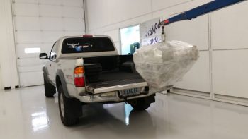
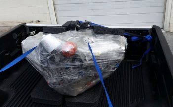
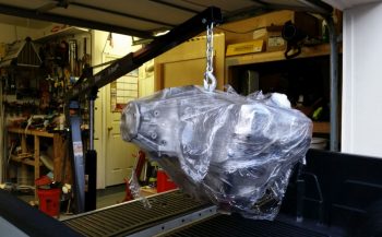
I will note that with the big task of welding up the engine stand mounting brackets and seeing my buddy Greg off over a couple of nights really put a dent in my schedule, and put me way behind the power curve time-wise.  Since I had a locked in rental on a moving trailer, and a locked in timeframe that I needed to be in NC, my back was somewhat against the wall.  Still, the primary goal here for me was to get this engine pickled, and then move what I could in the allotted time I had left.  I just was not going to risk any internal engine corrosion with any more time than was necessary.  In short, it was time to get this engine pickled.

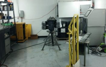
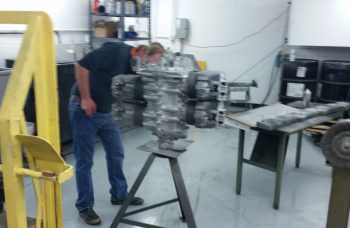
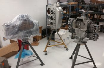
With having removed the engine last night from the fuselage, I then did the limited trial and error dance for getting the bottom engine stand mounting bracket mounted to the engine mount.

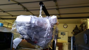
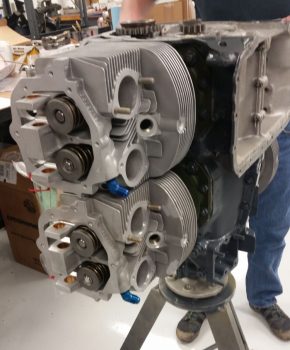
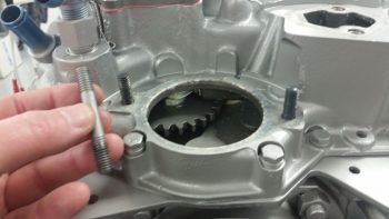
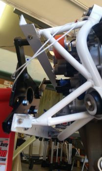
However, the top mounting bracket was the big dance, and it took a couple of hours to dial that baby in.  The primary issue was that I forgot how the engine mount stubs –and thus the engine mount extrusions– are at a slight angle to follow the fuselage angle (this is denoted in the plans).

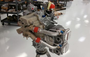
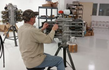
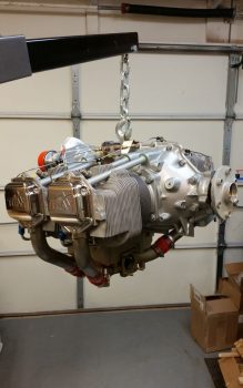
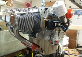
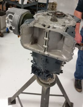
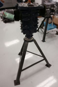
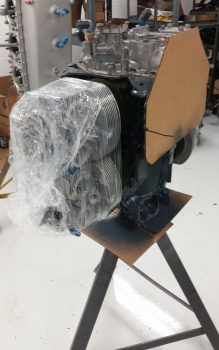
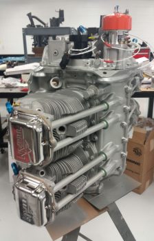
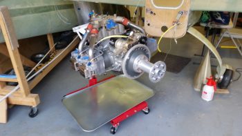
After much wailing & gnashing of teeth, a number of expletives and my new boneyard of broken drill bits (I think one side of the mount ended up so hot that it was in an annealed type state… since drilling a hole into it was like going through stainless steel) I finally got it all put together and then the engine mounted to the stand!

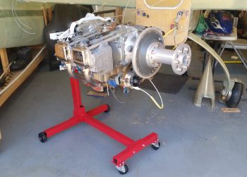
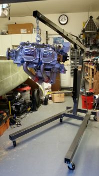
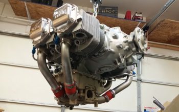
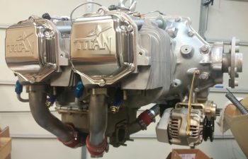
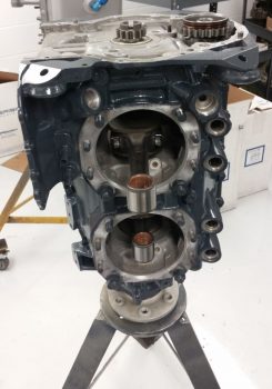
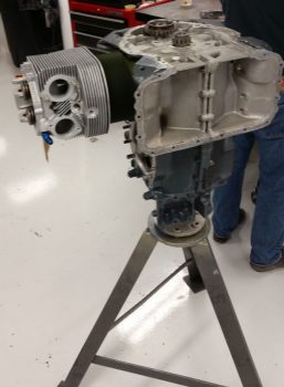
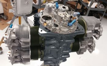
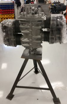
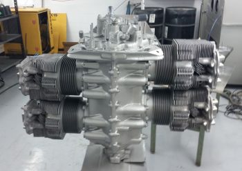
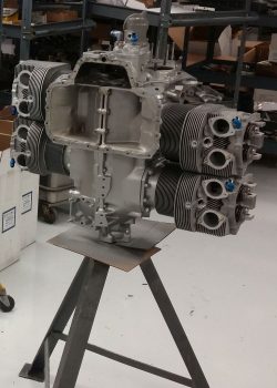
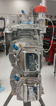
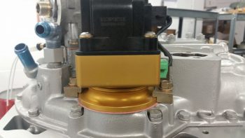
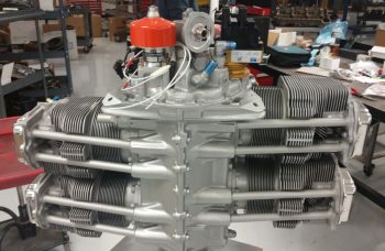
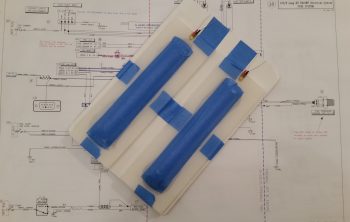
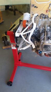
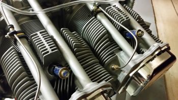
Here’s a better view of the engine mount attached to the engine stand mounting brackets.

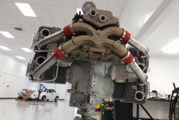
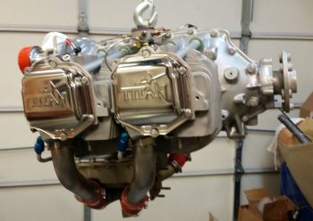
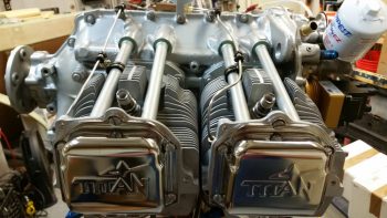
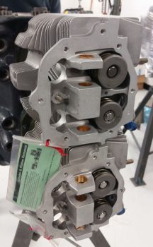
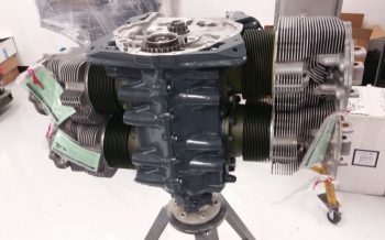
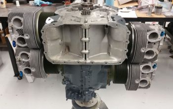
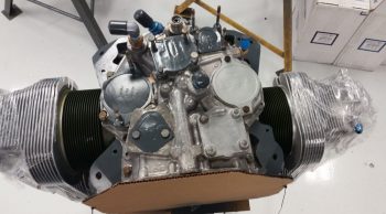
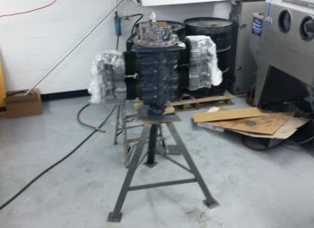
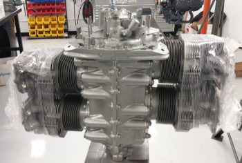
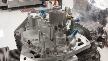
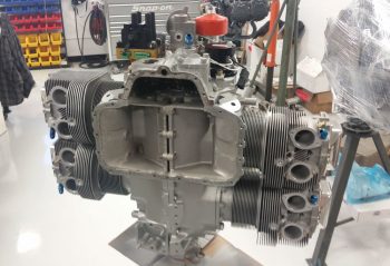
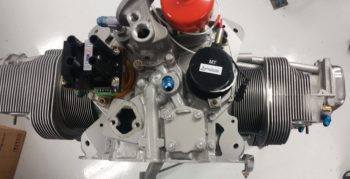
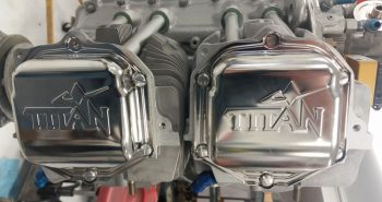
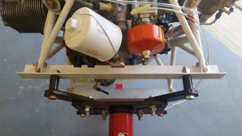
And a couple of views from the top.

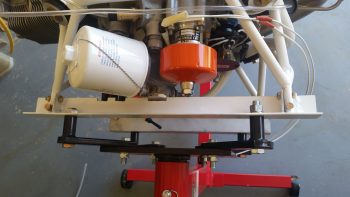
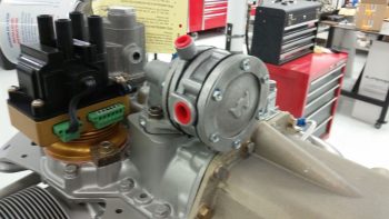
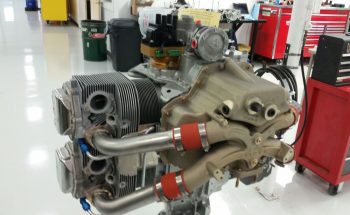
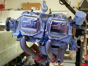
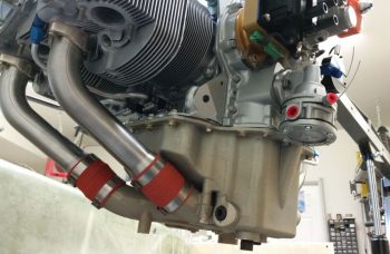
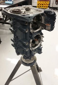
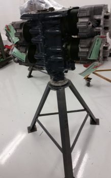
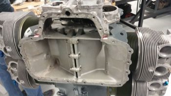
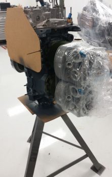
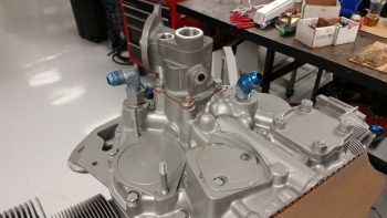
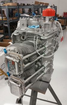
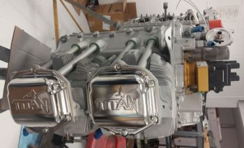
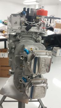
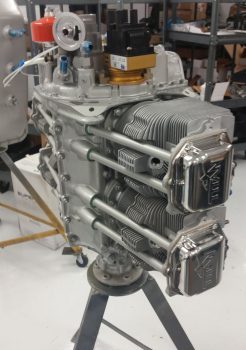
Ah, yes, and of course here we have a view more from the lower side.

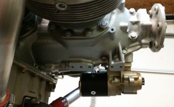
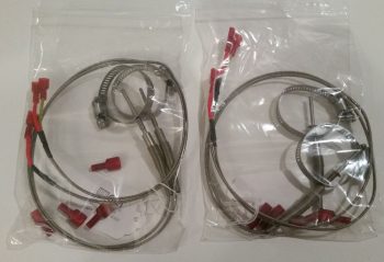
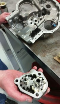
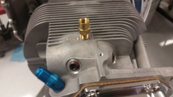
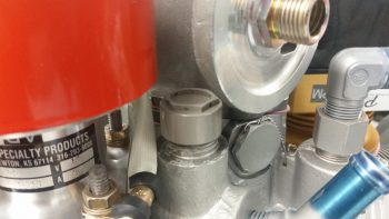
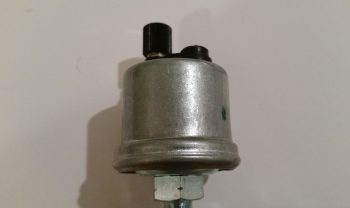
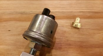
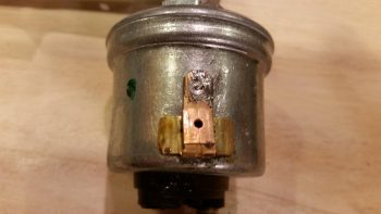
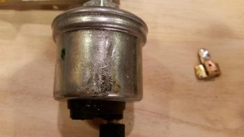
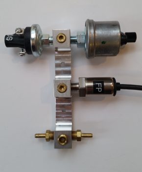
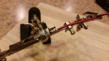
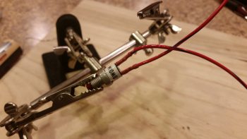
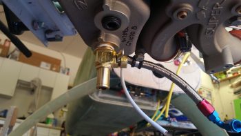
I also drilled a hole through the lip of the oil drain valve to accept a 0.041″ piece of safety wire.  I then threaded the oil drain valve in place.  Unfortunately I was remiss in remembering that this was a Japanese made oil drain valve, and thus metric, so my 3/4″ wrench was just a hair loose on it.  When I really went to snug it up that last little bit I rounded a couple of the wrench flat corners over.  I then grabbed a 19mm wrench to finish up the last little bit of snugging it up tight.

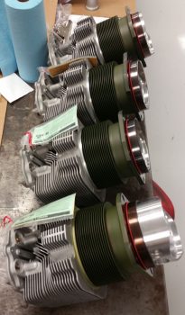
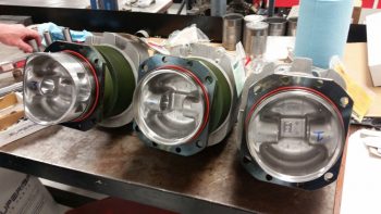
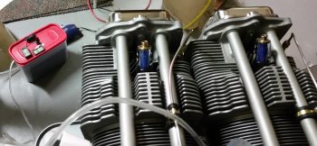
I removed the spark plug cylinder dehydrators from the bottom side of each cylinder and replaced them with standard aircraft spark plugs.  I then removed the top spark plugs while I squirted preservation oil into each cylinder, and then replaced them with standard aircraft spark plugs as well.

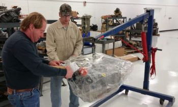
I sprayed approximately 2 oz of PolyFiber Engine Storage Oil (ESO) into each cylinder when its piston was in the down (inboard) position.  I will admit that I realized as I was prepping for the pickling of the engine that an optimum solution would have been to have cover plates for both the intake and exhaust manifold ports, but I didn’t have either, and again, since I was in a time crunch I pressed forward and simply placed an oil drip pan underneath the engine for any runoff.

I will say that I shown a pen light into each cylinder with the top plug out, and what I saw on the each cylinder wall gave me a huge sense of relief.  I could see the honing of each cylinder wall with bright shiny metal and NO corrosion…. which I’m very thankful for.

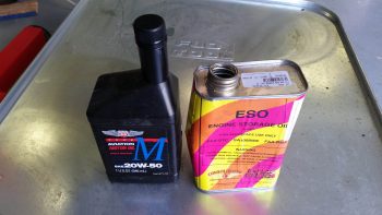
I then poured 3 quarts of Phillips 66 20W-50 oil into the engine, fed in the remainder of the ESO and then poured in an unused quart of Harley-Davidson 20W-50 to top it off.

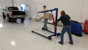
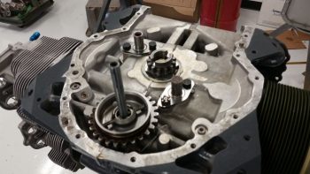
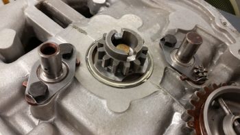
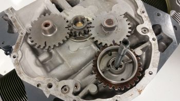
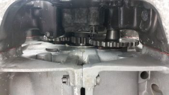
With my 4+ quarts of oil in the sump, I then flipped the engine upside down and let it sit that way for a good 5+ hours as I loaded up my rented moving trailer.  My goal here of course was to bath the top-mounted camshaft in a bunch of oil.

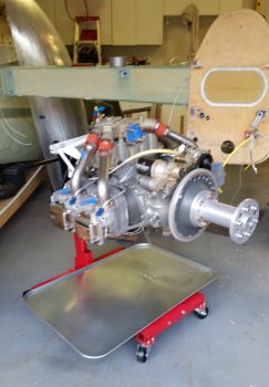
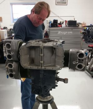
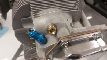
In my haste I failed to cap the oil heat return fitting so it spit out a bit of oil when I flipped the engine upside down.  Beyond that little issue the engine stand seemed to work exactly as I thought it would in allowing me to wrench on the engine and also rotate it as if it were on an “engine spit.”

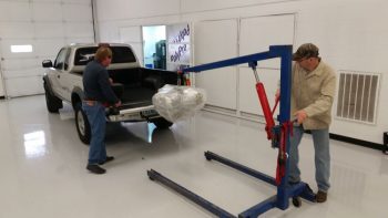
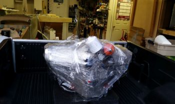
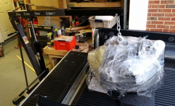
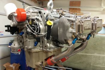
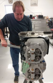
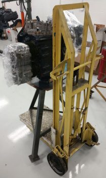
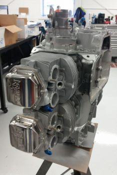
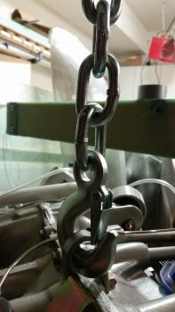
Before I left for NC I turned the engine back right side up and attached the hook of the engine hoist to the top engine lifting tab.  I’ll turn the engine back upside down when I return from NC, but since I just welded up the engine stand mounting brackets I didn’t want to test my luck (just in case).

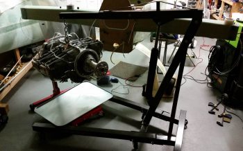
I did leave a bit of a gap between the engine hoist hook and the engine lift tab to allow me to quickly identify if any of the welds on the engine stand mounting brackets gave way while I was gone…. again, just a precaution with an expensive aircraft component.

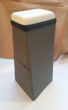
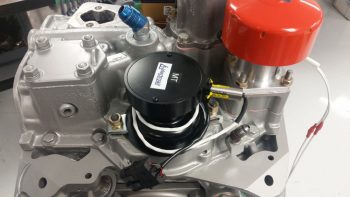
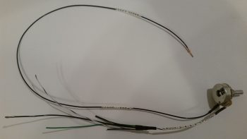
For the final push on the engine pickling, as I was working on the engine I was also concurrently baking up another batch of pink desiccant.  Once it had turned blue and cooled, I then recharged all the cylinder dehydrators and the main engine dehydrator bin.  I then removed the top spark plugs and replaced them with the spark plug cylinder dehydrators.  Note that now the spark plugs are mounted on the bottom of each cylinder with the spark plug cylinder dehydrators on the top.

Again, I’ll be gone for a few days, and with the engine now off the fuselage and pickled for the time being, when I return I’ll be putting all my energies into building the nose and canopy to finish off the aircraft centerline build.


Chapter 23 – Engine Build: Phase II

I started out this morning at around 0630, packed up the truck with all my engine accoutrements and headed off on my 1.5 hour trek up to Winchester, Virginia for the last phase of my engine build.  I had already talked to the builder, Tom, who let me know that during some down time in between engine builds that they installed the Superior cold air induction sump and the high pressure fuel pump, and sure enough that is exactly what I found when I arrived.

Here’s the high pressure fuel pump mid-picture, just to the right of the PMag ignition.

Here are a couple wider angle shots showing more of the Superior cold air induction sump.

Although it seemed they were eager to pack up the engine and for me to get it out of their hair, I did want them to finish installing the fuel injector nozzles, the fuel injector distribution spider (and bracket) and the 1/8″ stainless steel lines in between.  Another engine builder that I hadn’t met yet, Larry, undertook the task to hook up the fuel injection lines.

With the topside fuel injection components and lines in place, and after Frank I messed around installing, moving and reinstalling some AN fittings for the main oil line and the oil heat system return line, Frank and Larry then wrapped up the engine for its trip to MY shop.

Here’s a shot of the engine wrapping to keep any potential precipitation off of it.

With such a large shop, it was a bit of a trek to get the engine down to the other end to put it in my truck, but Frank and Larry dug deep and somehow mustered the internal strength required to make it happen!

And here we go…. history in the making.

The three of us got the engine set in place with thick foam-rubber pads and then strapped it down.

An hour and a half later, both the plastic wrap and tie-down tasks had worked well, and the engine was still right in place.

I’ll digress just a bit, because before I could unload the engine I had to finish Phase III of my shop cleaning and organizing to have enough room to maneuver the engine hoist. I wanted to move the fuselage dolly so that one end was against the side wall with the other end sticking out in space, which would still be less obtrusive than it’s shown here.

However, with my fuselage dolly also being my canopy storage container, I wanted to get the canopy out of it since I plan on starting the canopy build in the next month or so.

I was impressed at how good of shape the canopy looked after it’s multi-year hibernation in the fuselage dolly.

Plus I would now get the benefit of MORE STORAGE SPACE!

With my shop furniture cleaning and rearranging out of the way, I then got down to business getting the engine out of my truck and into my shop… I started by carefully removing all the tiedown straps.

After a brief 30-min break to recharge the engine hoist with hydraulic fluid, I then backed up the truck to the shop entrance, set the engine hoist in place, and clamped the hook onto the engine.

I carefully lifted the engine up above the truck bed, but since the shop floor slants down, both of engine hoist wheels were over the lip at the door threshold.  No matter what I tried, I just didn’t have a good angle to get the wheels over the lip.  I chocked the engine hoist wheels to ensure it didn’t move, and then very slowly and carefully pulled the truck forward.

With the application of some basic fulcrum and leverage techniques, using some spare dunnage, I was able to get the engine where it belongs . . .

IN MY SHOP!!!

Here’s one of many pics of the engine.

And another after I closed the main door and got to work checking out a number of things on the engine.

I spent a good bit of time assessing how the Silver Hawk fuel injection servo would get mounted to the cold air induction plenum.

Here’s another side view with the fuel injection spider lines somewhat visible.

Also, I was VERY happy that the guys at AERO Engines hooked me up with a short dipstick and oil filler neck! Thanks guys!

Although a minor detail, I also thought it was great of them to actually install a new oil filter and wire tie it in place for me…. as you can see in the below view of the accessory case end.

Here’s a low-angle shot of the front of the engine with the cold air induction oil sump and plenum in view, as well as the high pressure fuel pump.

Although I mentioned it on my last engine post, I really like the snazzy chrome style “Titan” valve cover plates vs the old metal painted Lycoming ones…. just my preference of course.

I then temp-mounted the starter to check out the fit and also see what hardware I would need to order for mounting it, if any (I actually need to order ALL the hardware for it).

I then mounted the alternator to check for fitting and potential hardware requirements.  Moreover, I wanted to check the mounting distance from the alternator to the starter which would tell me which B&C cross link I would need to order.

In addition, I mounted the spark plug dehydrators, put desiccant in a bunch of the open orifices and taped them closed with painters’ tape.

I am very happy that this significant piece of the puzzle in my build is essentially in place.  Of course there are still a myriad of minor bits to acquire, installations to do and deconflicting issues to be done, but it’s a great feeling having this thing in MY shop!

Tomorrow a goal is to get the engine dehydrator hooked up and ensure I keep the internals on this engine DRY.

Ok… back to it.


Chapter 22 – “Starter ON” Warning

Yesterday I got some rubber “T” molding that is used at the edge of auto windshields and the window frame for sealing a windshield edge.  I bought it off of Ebay because it was the only source of supply I cold find (I looked a while!) and had it shipped in from China.  I checked it out a bit last night, then this morning I trimmed it and mocked it up atop my pilot seat headrest (which will get repainted with my now standard interior scheme color later).  The molding looks like it will do a great job for it’s intended purpose of securing the GNS480 GPS antenna puck cover (aka “radome”) in place, given that I don’t have any glue, tape or anything securing the pieces together in the pic below.

I spent a few hours this morning replying to emails and updating my electrical diagrams in what appears to be a fairly controversial move on my part.  I’ll start by providing some background on my quest to find information on optimizing the firewall components’ layout and engine wiring transition through the firewall.

I remember reading about Brian DeFord’s Cozy burning up on the ramp due to an electrical issue at the firewall. I’m still not 100% clear as to what caused it, as he may not be either.  It was a tragedy and I’m sure heartbreaking for Brian, but I’m glad both he and his beautiful family were safe from harm in this incident.  One thing that Brian mentions is that he did not turn off the master switch at the first telltale signs of smoke, and within 20 minutes his stellar Cozy IV lay in a pile of ash with only the engine and winglets pretty much left.

This led of course to some major discussions on the Cozy forum and other venues about hot wires transiting through the firewall.  In my research I discovered a question asked by Greg Norman [I know Greg from RR16] to the Cozy forum specifically about mounting the starter contactor/solenoid on the cold side of the firewall.  There was fairly overwhelming consensus in those that replied that stated mounting the starter solenoid on the cold side of the firewall kept from having to have the big power wire traverse the firewall.

As I assessed this, I came up with a number of pros as to why I concurred that it was a good idea:

  1. In keeping the main power cable from transitioning through the firewall, it simplifies the corrective action for smoke or malcontent coming from the engine compartment in that the only hot wire going through the firewall (before start… after start there is of course the alternator B lead) is caused by the starter button/switch being engaged. To remedy a hot wire to the starter and cut power one merely STOPS pressing the starter button/switch.
  2. As per above, this makes turning off the Master Switch less of a critical step to remedy something electrical-related being amiss in the engine area to more along the lines of probably a good idea thing to do.
  3. The ancillary logistical benefits of moving the starter contactor to the cold/forward side of the firewall in routing wires is quite significant. It simply makes for running less wires through the firewall, wire runs to the Hall Effect sensor for both the primary and SD-8 backup alternators are optimized, and it places more items in the rather empty Hell Hole area and gets them off a very crowded firewall, just to name a few benefits.
  4. Below is a diagram I made to explain this.  Prior to my decision to move the starter contactor forward to the cold side of the firewall, everything in the diagram below was mounted on the hot/aft side of the firewall.  The main big power cable coming from the nose mounted battery contractor is the big line at the very top left half of the diagram.  Now that I’ve moved the starter contactor (planned, not executed …. yet) everything in blue is on the cold/forward side of the firewall while the alternator and starter are of course still mounted to the aft side of the engine.

Thus, in short, moving the starter contactor forward to the cold side of the firewall just really appears on the face of it to make for an easier install and a safer operational setup. Honestly, I might not have done it if there wasn’t the overwhelmingly increased ease of wiring it provides.

[I should note that I posted this as a question on the AeroElectric Connection forum, and in my discussion with Bob Nuckolls he does NOT seem to be a fan of moving the starter contactor to the forward side of the firewall.  I will also state that I have not received any clear reason from anyone, including Bob, up to this point as to why it would NOT be a good idea.  I have had a number of Cozy/Canardians say that they are or have done this, and are glad to have made the change.  Understandably, the folks who seem the most unenthused about this idea are not canard/pusher pilots/builders, but tractor aircraft drivers].

Moving on from the controversy, today I received the missing EGT probes from GRT…

and the missing CHT probes.  Thus I’m calling The Case of the Missing EGT & CHT Probes SOLVED!

I then got to work on at least getting one electrical task knocked out today.  Since I was already dealing with the starter contactor I decided to build the circuit that is used by the AG6 warning annunciator to alarm during engine start with a “Starter ON” annunciation.  If this red alarm annunciation does not turn off after engine start, or after a failed start attempt, then it tells me that the circuit is still live and that I need to take immediate corrective action (probably very close to what happened to Brian DeFord in his Cozy burning-up incident).

The circuit for the AG6 Starter ON warning cohabitates with the Starter lead on the downstream side post of the starter contactor, starting off with a 2 amp inline fuse [Note: The wiring diagram for my task here is shown in the diagram above on the right side of the page].  I grabbed another mondo-wired inline fuse assembly and assessed its eventually mounting in the vicinity of the starter contactor.

I then trimmed one leg down a bit, stripped the wire back and crimped a blue PIDG 0.25″ ring connector onto the end of the trimmed inline fuse leg.  When I crimped the terminal in place I clocked it so that it would be vertical while the body of the inline fuse housing was flat against the firewall.  Of course I had preloaded the wire with a piece of red heat shrink to place over the terminal after I crimped it.

Here’s another shot of the 2 amp inline fuse for the AG6 “Starter ON” warning annunciation lead.

I then hacked off the other leg a little over half-way.

I stripped a big portion of the insulation away.

I then teased out around 4 wires to create a pigtail for wrapping around the component leads for a tight junction when they would get soldered onto the lead.

When I talked to Rich at Aircraft Extras regarding the installation of the resistors for the AG6 warning input leads, he said the install manual required 2K Ohm 1/2 watt was a good ballpark for what can be used.  After that discussion, I’ve used 1.5K Ohm and 1/4 watt resistors on other AG6 leads without any concern.  But here, with this being connected on the same post as the one item that sees the biggest inrush current on the entire aircraft, I wanted to go with what’s called out in the AG6 install manual…. as a minimum.

The problem was I was out of 2K Ohm 1/2 watt resistors.  Hmmm?  Ok, well, I guess two of those 1K Ohm 1/2 watt resistors in series will just have to do!  So, I improvised, adapted and overcame … and pressed forward with my 2 resistors in series.

I then soldered the two 1K Ohm 1/2 watt resistors together….

and trimmed the excess leads.

I then (mistakenly . . . sheesh!) tied the resistor set and a diode together at the end of the 2A inline fuse lead.

And soldered that up.  But something wasn’t right.  Yep, strange things were afoot at the Circle K.  When I checked my diagram I quickly noted that I had tied in the diode at the wrong point.

So I snipped the diode off and soldered it in parallel with the white/orange lead that heads off to join up with the white/orange lead from the 6-wire cable that heads up to the panel avionics area.  The diode that I relocated is a protective diode that simply goes to ground and protects the line from any massive amounts of juice from frying anything.

I then added protective heat shrink to the whole shebang and called it good.

And then did some labeling of the inline fuse housing (“IF007”) as well as the inline fuse housing I configured for the SD-8 the other day (“IF008″… not shown).  Of course when I get some more wire labels here in another week or so I’ll label up all the unlabeled wires I’ve just created over the past week.

Besides all my crazy antics above, I also did a fair amount of research and identifying what to buy for the next round of electrical tasks.  I really think the parts requirements for the electrical system will continue to dwindle exponentially over the next few months as I get closer and closer to dialing in the electrical system to its final state.  And again, tomorrow will be more of the same on knocking out electrical system tasks.


Chapter 23 – Engine Build Phase I

Ok, let’s get started . . .

It was a dark & rainy morning (really) this morning when I loaded up the truck and I got on the road around 0630.  The rain made the typically slow DC-area drivers drive even more slowly, so I got to the main A.E.R.O Engines office at Winchester airport just a hair after 0800.  It didn’t matter though because the owner, Tom Schweitz was over at the engine assembly building across the airfield.  So I drove over and met Tom, who then introduced me to one of his master engine builders, Frank.

They showed me my engine with the crankshaft already mounted up in the crankcase on the build stand.  Since there was some confusion over whether I should have 1/2″ or 7/16″ prop flange bolts, they installed a brand new 340 strokered crankshaft with 1/2″ prop bolt flange into the Lycoming crankcase that I had bought from Tom back in July 2013 (right before I went to Qatar for a year). [NOTE: There was a bit of confusion on my side as well, so when I sent the prop extension back to Sam at Saber Manufacturing to have 3/8″ prop bolt mounting holes drilled for a Hertzler Silver Bullet prop, I also had Sam drill out 1/2″ prop flange mounting bolt holes in-between the 7/16″ holes.  In the end, it cost a bit more, but it all worked out and I can now use a lot of different props on a lot different engines with this prop extension]

And here’s the 4 brand new cylinders and pistons, that come as a matched set for flow and weight.  I had originally planned on going with tapered finned cylinders for weight reduction, but in the end decided against them since these below not only cool better (obviously more surface area) but if I ever have just one jug go bad on a trip, I can simply replace the offending cylinder with a common Lycoming/Superior/ECi vs having to track down a tapered fin cylinder (from Continental now since they bought out ECi).

The pistons are a standard low compression piston ~8.5:1 but when strokered the output is equal to 9.2:1 higher compression pistons.  This configuration alone will typically dyno out at 185 HP.   But add cold air injection and RAM air and it should result in numbers well over 190 HP, so I don’t need to thrash the cylinders with even higher compression pistons just to add a few more horses.

Luckily I grabbed a couple of quick pics of the crankshaft in the case and all 4 ECI cylinder/piston assemblies (above), because by the time I got out the door & back with a load of some of my engine goodies Frank already had one jug and piston mounted to the crankcase/shaft.

Here’s a look at the first jug in place on the crankcase.

And here’s another look at the cylinders with each respective piston inside its cylinder.  This setup makes it much easier and faster to build the engine since there’s no messing around with wrangling oil rings to get the pistons into the jugs.

Again, another load of my engine accoutrements and yet another jug in place!

Here is Frank on jug #3 (I’m not going by cylinder #s, just order mounted).

And cranking down the myriad of bolts that hold these beasts in place.  I have to tell you, the specialized tools this shop has made this job look REALLY easy!

Here’s a closer look at the top of the valve springs and cylinder heads.

About the time I finally got my engine gear situated, cylinder #4 was in place with the bolts getting torqued to final specs.  As bantering ensued, I was a bit relieved that the conversation turned to what color paint I wanted the engine, INCLUDING the cylinder barrels.  We had a good laugh when I conveyed that I had been having some initial concerns over the odd color combination.

Here’s the bottom of the engine where the Superior cold air induction oil sump will get mounted.  Unfortunately, we discovered that the one I had ordered from Tom got scarfed up on some other build, so Tom had to order a new one that won’t arrive until next week.  Yes, for all you Air Force types: “Flexibility is the key to airpower!”

A longer shot of the completed cylinder mounting.

Frank then pulled out a somewhat raspy looking accessory case.   He explained that just like the engine core, a lot of larger components get reused during builds, and that the cleaning/degreasing process actually makes them look a little rough . . .  and thus part of the common practice of painting of the engine cases!

On the engine side, the two separate idler gear posts are placed on either side of the smaller oil pump gear.  The larger gear towards the bottom of the screen is the camshaft gear.

You can see on the idler gear posts the bend up tabs that are used quite often in lieu of safety wire.

Then the idler (“mag”) gears slip in over the idler gear posts and get marked and placed in relation to each other and TDC.

Frank then lubed up the internal oil pump gears and mounted the oil pump assembly into the accessory case.

Then applied some RTV-type sealant in a few spots around the crankcase & accessory case interface, threw a gasket on and proceeded to mount the accessory case in place.

A shot of the bottom bolt attach points for the Superior cold induction oil sump on the bottom of the accessory case.

And a shot of the gears inside the accessory case housing.

We then wrapped up the jugs and placed protective plates in place, including the large piece of cardboard on the engine bottom, to prep the engine for paint.  In the background in the pic below you can see a large 6-cylinder Continental motor being built.  I wasn’t overly thrilled with the blue/gray color (it wasn’t terrible, but I preferred a color that conveyed a bit more of “Formula 1 race car” and a bit less “tractor” to me), they didn’t have the high grade black engine paint on hand (they don’t buy it because Tom hates painting motors black!) . . . so, I went for that Continental silver in the background (anyone who knows me… and my truck, knows that I really like silver vehicles.  So it worked out great.)

Another shot of the engine prepped for paint.

We then picked up the whole engine, stand and all, and moved it down the long building to the paint booth.

Here’s the engine in the paint booth ready for a makeover.

And here it is sporting its new sexy silver color… love it!

Again, in different light.

We found a couple of small spots that Frank missed, so back to the paint booth for some touching up on the paint job.

Again, love this silver . . . very nice (IMO).

We then got to work on the accessory case by mounting the 90° oil filter adapter.

Here’s another shot of the oil filter adapter.  As a point of note, only the plate on the far right is real.  All the others are simply covers to keep the paint out of the holes.

I took this shot just to show some of the concurrent engine builds they have going on… incredible.  If you’re not sure, my engine is the one on the right…. (big smile).

A close-up of my engine build in progress . . .

We then installed the SD-8 backup alternator on the vacuum pad.  This was done after Frank had installed all the valve lifters & tubes, valve rockers, and some outstanding Titan covers that Tom dug up (no painted “Lycoming” valve covers for me! <grin>)

Another shot of the engine build in progress.

I then dug out my brass fitting insert that has a very small outlet hole and serves as the transition from cylinder head to braided manifold pressure tubing.  Below the brass fitting insert you can see the hex plug that will get removed so the brass manifold fitting insert can be installed.

I then installed the brass manifold fitting insert.

Here’s a longer view of the brass manifold fitting insert and the mounted SD-8 backup alternator.

We then set our sites on the “mags.”  I have to say it was an interesting environment because, although it was very loose and fun with the guys, they don’t do or understand the experimental world.  The stuff I brought was all very new and a mystery for most of these engine builders (except for Tom…. thank goodness, since he often served as my “interpreter”).  Thus, I double-checked the manual on the Electrair electronic ignition Mag Time Housing installation . . .

to ensure we got installed correctly in relation to TDC.

Since we didn’t require a Mag impulse coupler on either side, both sets of long threaded studs had to be removed out of the accessory case and replaced with shorter ones.  In the pic below I’m holding one of the longer studs, with the shorter ones already installed.

We then installed the P-Mag.

We then installed the Andair mechanical tach port cover.

Another wider angle shot of the population-increasing accessory case.

I took this pic below to show what it would like to view the engine from the side, as it sits in the aircraft.

Another view of the bottom side of the engine.

A side view . . .

A quarter view.

A slightly fuzzy shot of the increasingly populated accessory case, with the P-Mag, 90° oil filter adapter, SD-8 backup alternator and Electroair MTH all installed.

Here’s a closer shot of the shiny “Titan” valve covers indicative of the IOX-340S engines.  Again, stylistically I’m glad that they had these on hand (as a very busy build facility for certificated engines they just don’t keep a lot of experimental stuff around… for long at least).  I much prefer these than the dull painted ones with “Lycoming” stamped into them.

Here’s one more quarter view of the right side of the engine.

And one more quarter view of the left side of the engine.

The weather will remain somewhat cold for a bit, so tomorrow I’ll press forward with finalizing my EIS4000 and HXr engine parameter input swap and configuration, as well a few more minor electrical system tasks that I have.


Chapter 22 – Inverting fuel gages

Last night at some point I was thinking about the actual physical wiring of the aft two cameras that each focus on a fuel site gage.  I knew that before I could finalize my decision that I would have to test and verify that 24 AWG wire would provide enough juice for the cameras to send a good video signal.

What was gnawing at me was an issue of consolidation, and one of cable management. Dealing with 3 separate 24 AWG wires isn’t an insurmountable task, but I thought there might be some efficiencies to be had.  I drifted to sleep with this on my mind.

Then there was the question I had this morning regarding those pesky LED lights on the fuel site gauges themselves. Hmmm, how will the wiring on these critters actually physically get run?

Then I had an idea.  An idea that has eluded me for almost 7 years, considering Vance Atkinson’s fuel site gages are the first components I purchased, IIRC, for my Long-EZ project: What if I inverted them and put the LED on top?  I pulled the installation instructions out to find, lo and behold, that the last line on the page –hand written– said that I could mount the LED on top OR bottom.  Cool!

With that info in hand, I then planned initially –to be verified with some camera tests– to use a 5x24AWG conductor wire to handle both my aft camera and fuel site gage wire runs. Each aft camera would use 3 of these wires while each fuel site gage would use the remaining 2 wires…. again, all 24 AWG wires packaged nicely in one cable.

Since I don’t have any wire label stock on hand (they should arrive tomorrow) the first thing I did today was something else I haven’t done in almost 7 years, I tested the “red” LEDs (as listed on the included specs & install sheet) on the fuel site gages to find out that they A) worked, and B) are in fact actually white LEDs, not red.

I then took about 45 minutes to get some low hanging and long overdue bits ordered.  I finally found and ordered a couple of pieces of 1.5″ diameter heat shrink off of Ebay (I checked McMaster-Carr, WAY too expensive) primarily to encase/protect my relay that controls COM1-COM2 radio flip from the control stick.  I also ordered a length of a rubber automotive seal that I’ll use for mounting the GNS480 GPS antenna puck cover atop the pilot headrest (after 20 min the ONLY source of supply for what I wanted was again off of Ebay, and straight from China no less).

I then got to work on my wiring diagrams to upend the Atkinson fuel site gages and depict their new orientation correctly.  I also better depicted their actual physical wire runs and added in the visible segment of the 5x24AWG conductor wire.  I have two diagrams, fuel system and cockpit lighting, that contain the fuel site gages so I tweaked one of them to the new “final” configuration and then merely copied over the entire new depiction to the other diagram.

I then spent a few hours doing something I haven’t done in a fair while: I created a new wiring diagram for the Video Camera Network.  Here is a saved JPG version of that diagram.  I was putting the cart before the horse slightly in that I hadn’t tested out the 24AWG wires –at least the non-shielded wire version– for the video cameras, but I was quite confident that it would work.

After compiling all the data I needed to represent the Video Camera Network wiring on a system diagram, I then set about testing my 24 AWG hypothesis.  Fortunately, I found about a 7 foot length of the exact 5-conductor wire I want to use for the aft cameras, so this would be a great representation to check the video display quality using near the same length of wire.

I then stripped off the first couple inches of the outer insulator and grabbed 3 of the wires to hook up to micro-video camera #1 for testing.  I soldered the wires to the camera leads off the tiny PCB board that the camera uses for 12V-to-5V conversion, and then hooked up the camera at the EFIS side.  I fired up the EFIS and as you can see in the lower left inset, I got a very readable video display from the camera.

Since this camera is going to be used to view the fuel quantity in a fuel site gage, I amused myself (yes folks, constant electronics will drive you stir crazy!) by placing the still-wrapped site gages in the video camera’s view to snap the pic below.

I then spent a good 20 minutes desoldering a connector off a PCB board (I stole it off the defunct 5v GNS480 indicator light that burnt up) and then soldering three 22 AWG wire leads to it.  I then connected my 5V “wide angle” video camera #3 up to the EFIS and 12v-to-5v converter to test it out.  As you can see below, although not nearly as “wide angle” as I was expecting, the video display quality is fine.

Now, I noted that a few of my 5V components go from 5V+ power on the positive lead then simply hook up to standard 12V ground on the negative lead.  Since these cameras depict and physically have a both a positive and negative side for the video signal (via the yellow RCA jack) and on the camera power input (via the red RCA-type jack) I figured each component needed a direct connection to ground.  I noted this concept was supported in Eric and Alec’s design of my 4-into-1 video signal sequencer, since on the unit’s D-Sub connector they placed a signal ground pin right next to and for each video signal input pin. Moreover, also on the unit’s D-Sub connector they had a pin for camera power and another for camera ground.  Ok, so that’s how it needed to be wired (allegedly).

But back to my 5V ground vs 12V ground, as I was testing the grounds on camera #3, I pulled the ground off the outer ring of the video signal RCA jack which resulted in ZERO impact to the video signal.  It was still right there on the screen.  In fact, I moved the camera just to ensure no weird screen capture event had occurred.

Hmmm, interesting.

Ok, so then I disconnected the ground path to the 12v-to-5v converter.  The EFIS video inset screen went blank.  I then tried re-hooking up the ground to the outer ring of the video signal RCA jack…. still no video signal.  Reconnecting camera ground brought the video back live again.

So the 2-ground requirement I had noted in the camera install manual does not seem to apply, at least for seeing the video signal.  I’ll have to double check in the manual to see if it keeps the unit from errant electrons or something.  Moreover, I tested this on camera #1 by hooking it back up and found the exact same results: no ground lead required on the video signal RCA jack.  Not a huge find in how it impacts the amount of wiring effort, since it merely eliminates 3 small ground lead pigtails… but it is nice to know.

I depicted this on my new Video Camera Network electrical diagram and with confirmation that the 5x24AWG conductor wire will work I then labeled all the wires with the appropriate wire colors.

Again, tomorrow I should be getting my wire label stock delivered so I can get back to finishing up some tasks that require wires to be labeled before next steps can be completed.


Chapter 22/23 – Bad Assumptions…

will get you every time!  We all know the saying about assuming, well I “went there!”

Before I tell you that story of woe, first some successful task completions.  My first order of the day when I went upstairs to work on some even more tweaking of electrical diagrams was to hook up my nose gear auto extension system’s laser altimeter to my PC via the included USB cable to finally configure the settings.

After I downloaded and installed the Lightware terminal program, I then proceeded to set all the operating parameters for the laser altimeter.  Of course that meant going paragraph by paragraph through the manual to make sure I didn’t screw anything up!

As I was tweaking the electrical diagram for the engine systems and EIS4000, I wanted to investigate further a note I had on my VDO HPS-01 Oil Pressure sensor.  The manual states that the case must be grounded, but the sensor only includes one terminal for the signal wire. As I went back through my notes I had highlighted a myriad of issues builders had had with these VDO sensors . . . mainly in wonky sensor readings caused by poor or no grounds.

Enter rabbit hole!  Well, I wanted to get to the bottom of this since it was a point on my electrical diagram that was cloudy and unknown to me.  I wanted an answer to this riddle so I could press forward with this variable turned into a constant.  After an hour or so of researching my notes, manuals, forum posts (mainly VAF) and other notations, even from canard heavyweights like Marc Zeitlin, I came to the conclusion that my VDO oil pressure sensor, did “in fact,” need a grounding tab attached to the case as spelled out by the EIS4000 manual, et al.

I looked online for these tabs, and after not being able to find a source of supply, I decided to construct one myself from some multi-connnecting Fast-ON tabs I had on hand.  I simply bent the wings of the female connector out to then create curved “wings” that could then be attached to the case of the VDO oil pressure sensor.

Patting myself on the back for my sheer ingeniousness, I then read up on brazing vs. soldering, concluding there that with brazing being generally 5x stronger than soldering, I should “in fact” go that route.  I perfected my expertise by watching a few YouTube videos on brazing, and with my newfound knowledge in hand I ran down to Lowe’s and grabbed some bronze brazing rods.  Ah, my plan was coming to fruition!

I got home, cleaned up both surfaces to be brazed with steel wool and then some wipes with Acetone.

I had let a wood board soak in water while I was gone and used that as the underlayment for my project.  Yes, all ready to go!

And then the “fun” began…. with my portable propane torch I attempted to get this baby red hot.  Well, after not doing that, but inadvertently burning some of the plastic assembly on the top side of the sensor (merely cosmetic) and realizing my best attempts of getting any bit of the brazing material to lay down was a lesson in futility, I called it quits.

Hmmmm?!?!?!

I then decided that since I had a fair bit of surface contact between tab and case, I would try my hand at soldering the tab onto the case.  Again, no joy!  The case seemed to be impervious to any attempts to attach anything to it!  Crazy . . . .

Here’s the sad aftermath of my attempts to attach a grounding tab to the side of my VDO oil pressure sensor.

Now, here’s the kicker.  I did learn a lesson in all this.  After failing miserably above, I went back into research mode.  What was the deal with this VDO sensor?  Did they make others (they do) with a terminal for a ground wire (they do).  Hmmmm?  So I uploaded all my pics, put my notes in my blog to finish in the morning, and then called it quits for the evening.

However, as I was getting ready to head to bed, I was looking through pics of installed VDO oil pressure units in aircraft.  Now, I knew if it was installed straight to the engine case (which is a no-no in itself) that it didn’t need a ground wire since the case was grounded. But I was seeing pics of remotely mounted 1-terminal VDO oil pressure sensors like mine WITHOUT a visible grounding wire!

What gives?!

Thus the need for my ground wire . . . or . . . wait a minute!  Ahhhhhh! I quickly did a continuity test on my engine sensor manifold block and –Voila!– it’s conductive!  I got a solid tone with one probe on one end and the other probe on the VDO oil pressure case at the farthest point I could get from the first probe.

Thus, my ASSUMPTION that the manifold block was a non-conductive aluminum spun me off on a wild goose chase and caused me literally hours of un-needed effort!  Combine that with the note on the GRT EIS4000 diagram that states: “The case of the sensor provides a ground connection for VDO type sensors.”  I had simply allowed the word “case,” combined with all the horror stories and accounts of the requirement to attach a grounding tab lure me down a road that was entirely unnecessary!

Ok, so here’s a shot (I cleaned up the nasty brazing/soldering marks off the VDO oil pressure sensor with steel wool earlier) of my engine sensor manifold with the sensors attached.  The top left is of course the VDO oil pressure sensor that sends a signal to the EIS4000.  The sensor beneath it is a simple backup oil pressure switch that drives a “Low Oil Pressure” light on the AG6 warning annunciator in case I lose my EFIS, EIS, etc. The sensor with the black cable running out of it is the Fuel Pressure sensor.  On the right you can see 2 brass barbs, one is for the PMag MAP tube and the other tube runs through the firewall into the hellhole where the Electroair and GRT MAP sensors are located.

At this point I’m not sure exactly where or in what orientation the engine sensor manifold block will get mounted, so I included a pic showing it oriented vertically.

I should note that in addition to all the antics above, I spoke with my engine guy up in Winchester, VA.  We scheduled the engine build for the end of next week, so again, I’ll start ramping up for that in earnest early next week.

Tomorrow I plan to get back to the plan, and that is to really make an honest attempt to finish labeling my power busses!


Chapter 22 – Bringing boring back…

Snooze alert!  The stuff you’re about to see is boring …. good heavens, even I’m bored with this stuff!  I tell ya, the one good thing about working seemingly endless hours on the mundane tasks is that it really makes you itch to get back into the shop and sniff epoxy.

I spent over 5 hours yesterday scrubbing & updating every wiring system diagram I have on hand.  I figure that if all goes according to plan that this will be the last winter I have before my first flight to knock out all this nitnoy stuff…. again, much of it that I haven’t gone over in quite a while.

Today I spent a few hours on the phone discussing build topics with another Long-EZ builder, it was a great discussion but it put a sizable dent in my schedule. Why build airplanes when you can TALK about building airplanes?! … ha!

I then did some more cleanup on a few more electrical-related docs before getting down to business.  After attaching about a dozen wiring labels, I then stripped off some of the heat shrink over the solder splice on the Electroair electronic ignition’s control unit ground wire.

I had removed a Deutsch connector a while back and simply soldered the 2 wires together, but now I needed access to that solder joint to splice yet another wire into the mix: the 22AWG lead that will be the negative input (V- In) to the AD626 op amp board for Spark Advance reporting to the EIS.  Again, the signal coming out of the Electroair control unit is too weak so I need to literally amp it up by a gain of 10 so that the GRT EIS can use the strengthened signal to report the Spark Advance to the EFIS screen.

After exposing the original solder splice joint, I then soldered the 22AWG wire into the joint.

I then recovered the new solder splice with some more heat shrink.

Next, I focused on my 12V-to-5V power converter.  What will it be used for you ask?  Well, in order to use an aft-looking wide angle video camera that I’m going to mount at the top of the headrest, I need to use a 5V power signal to drive it.  In addition, I want to mount and use my Bendix/King AV8OR portable back-up GPS in the lower left corner of the panel, which too uses 5V power.

So I made up, labeled and terminated the power and ground wires for the 12V-to-5V power converter and screwed them in place on the terminals.

I have a power wire jack on order for the BK AV8OR GPS, and I need to acquire some 24AWG wire before proceeding with wiring up the video camera, so below is as far as I’m going to go on the 12V-to-5V power converter for now.

I then assessed and marked the plywood instrument panel mockup to drill a 3/8″ hole for the panel ON/OFF indicator LED lights’ dimmer.

After drilling the hole and cleaning up the sawdust, I then test mounted the dimmer switch and knob…. not bad.

I then got to work on cutting and soldering the panel ON/OFF indicator LED light ground wires to the dimmer switch.

While I was in the vicinity, I also removed the panel ON/OFF indicator LED lights’ Push-to-Test switch and soldered the power leads to it as well.

I then added heat shrink over the soldered leads for protection.

Tomorrow my focus will be on getting the Power Busses labeled, which was part of my tasks today in doing some final determinations on what components go to what tabs on the power busses.  I also updated some ground bus tab and connector pin assignments.

Yes, this stuff can be mundane and boring at times, but it is quite necessary and has proven worthwhile considering the number of small oversights that I keep finding on my diagrams and spreadsheets.  I think nearly all the clerical mistakes have been corrected now, allowing me to start off 2018 with all my electrical system docs and diagrams in order!


Chapter 22 – “Deslumpifier”

Alas, in light of the amazingly cold wx we are currently experiencing on the eastern seaboard of the United States, I’ve continued my quest to cross to-do items off my list, whether it is as banal in nature as simply ordering parts.

One such part I recently ordered was my instrument panel eyeball vent to allow me to focus heated air towards the upper part of me during cold flights.  I can tell you that right now that sounds like an especially good feature to have!  This Aveo eyeball vent was actually a bit tricky to decide which version to buy.  At first I was leaning towards anodized silver, even took a small poll.  But after getting everyones’ input and then spending a bit of time looking at both panel pics online and at my own panel, black just seemed the right way to go.  I’m sure in a week I’ll want silver again… argh!

I also received my “Deslumpifier” from electronics guru Eric Page.  He did a great job and his Voltage Slump Eliminator construction looks very professional.  It’s not too obtrusive in size and will add a great feature to my panel by allowing me to simply enter an entire flight plan into my GNS480 GPS navigator –on battery power and thus stress free regarding time (e.g. NOT sitting there burning mucho dinero in the form of 100LL)– before I then power up the engine whilst leaving the GNS480 on.  Good times!

After checking out the “Deslumpifier” I then spent well over an hour updating my engine management system and panel power electrical system diagrams, as well as creating a sheet to cleanly annotate all my current GRT EIS4000 configuration settings.

Another nice little surprise at the very beginning of 2018 was a text I received from Marco pointing out an announcement on Grand Rapid Technologies’ website.  They are now offering the special features package (EIS data display, Bluetooth and ADS-B display) for free on their Mini-X and Mini-AP EFISs.  Well, it ended up that I didn’t qualify for the “free” package, but I found out that I could get it at a greatly reduced price when I ordered my last GRT engine sensor: the Hall Affect Amp sensor.

Since I have Bluetooth and ADS-B on my HXr, I wasn’t concerned about those displaying on my Mini-X.  However, I did really want the capability to display engine data on my Mini-X in case my HXr EFIS display died inflight, so I pulled the trigger and ordered the software.

What I didn’t realize was how well laid out the Mini-X engine data display would look (IMO). A few hours after pulling the trigger on the software, I received an email from GRT and was able to update my Mini-X to display engine data.  I have to say that I’m really pleased with how it looks (of course, again, these pics don’t do it any justice!).

Here’s a wider angle view with the checklist displayed in the lower left inset on the HXr.  I did this to simply show that if I was messing about with a checklist, or had a full screen map or approach chart displayed, that with two button clicks I can very easily bring up the Mini-X engine data screen.  So, not only is it a great backup feature to the HXr, but it clearly offers a lot of flexibility to provide flight-centric information in a variety of ways.

Tomorrow should be another electrical tasker day in that I’ll most likely be doing a lot of wire & component labeling, and attempting to finish up so much of the small electrical items on my to-do list, nearly all of which are currently panel-related.


Chapter 22 – Programming EIS

The last few days has once again been ones of digging into my various engine, engine components and engine sensor manuals both for research and education on the operating limits of each item that will be tracked by the GRT EIS4000 Engine Information System.

As many of you are probably aware, GRT’s EIS Engine Information System was the first product produced by GRT back in 1991 as a result of GRT founder Greg Toman’s search for an automated engine management system for a 2-stroke ultralight engine.  Since he couldn’t find one, he simply built one!  How’s that for the spirit of homebuilt aircraft?

Barring some sideline and unexpected maintenance issues on my truck, today I was able to get both the initial and secondary (more refined) engine sensor upper and lower limits configured into the EIS unit.

Additionally, Nick Ugolini was kind enough to share his EIS4000 wiring configuration diagram with me as well, which served as an excellent qualitative crosscheck on my configuration. Moreover, my decision to mount the EIS4000 control head in the GIB headrest (i.e. “D-Deck” or “Turtleneck”) was based on Nick’s configuration that he shared on his blog (admittedly, in my ignorance at the time I didn’t think it was best to mount the unit so far aft… but it didn’t take long to realize that it was a great idea).

You might be asking how exactly this EIS control unit mounted in the GIB headrest displays engine data on the panel EFISs.  It’s actually very simple in that it relies on one 22AWG wire RS232 serial connection between the EIS4000 and the panel mounted HXr and Mini-X EFISs.

Besides just getting the unit powered up, as you can see in the pics I was able to get some “stick time” on navigating through the EIS4000’s menu pages and getting the initial settings configured.  Also, by assessing the configurations on my AUX ports I was able to play the shell game on paper and reassign 3 of the engine sensor connections with newly associated AUX ports which allowed me to avoid major re-configurations of EIS menu items.

Tomorrow I have some more digging around in the manuals for some “final” verifications on some of my upper and lower limits, such as the ECi IOX-340S’s EGT and CHT numbers.  I’ll also continue prepping for the engine build and knocking out panel wiring tasks.


Chapter 22 – Engine Info System

The weather here is VERY cold, dipping down to ~10° F (-12° C).  So NO shop work when it’s that cold.

On the good news side of things . . .  I got an email from Eric Page, the friendly neighborhood electronics guru off the AEC forum.  He has finished my one-off “Deslumpifiier” that should allow me start my engine with my GNS480 already turned on & flight-plan loaded.  Eric also just sent the completed circuit board up to Alec in Canada for chip coding the onboard 4-into-1 video camera signal processing unit that will feed my GRT EFIS video inset view capability.  This video signal combiner component will end up being about a 6-7 month long collaborative effort by the time I get it into my hands, so again, I’m glad to be getting the more esoteric instrument/electrical requirements through the queue before the real avionics install takes place.

In addition, Eric is close to finishing the tiny circuit board that will have the Bob Nuckolls’ recommended AD626 op amp chip mounted onto it, which will crisply increase the Electroair spark advance signal x10 to allow a very granular input into the GRT EIS box for displaying realtime Electroair electronic ignition spark advance data on my EFIS screen.

Moreover, since it’s currently so cold, today I started working on finalizing my engine info system installation requirements and EIS wiring harness prep.  The bottom line here is that I really need to dig into the manual on my GRT EIS4000 unit to get much smarter on it, both from the installation and wiring standpoint, and the operational integration with the GRT EFISs.

So I’ve been confirming all of the connections for the EIS input sensors, and taking a good inventory of each sensor to confirm what will be plugged into each specific port. I’ve already rewickered and refined some resistor placement requirements, and am confirming literally every configuration –both physically and software-wise– for each connection.

In the next day or so I also plan on doing a bunch more cleanup and labeling on my instrument panel wiring as well, as well as braving the cold shop for some metal work to physically mount the AHARS unit to the Triparagon top cross shelf . . . and figure out my bracket/cable attach points for the 3 heat/air levers.

Over the next few days, I’ll also start gathering all my engine accessories and hardware in prep for my mid-January engine build.  I also need to do as much reading as possible regarding the engine build to get much smarter in that area too.