Chapter 22 – Executive Decision

If you’ve been following my blog you know that I’m on a brief hiatus from building to finish up my Instrument rating.  My plan is to finish up my rating by mid-March, at which point I plan on getting back to the build hot ‘n heavy.  Who knows?!  Maybe I’ll even finish up installing those wheel pants! ha!

One reality that I had to accept as I was preparing for an upcoming Instrument flying stage check was my lack of understanding of the Garmin GNS430 GPS navigator, which is installed in all the Cessna 172s that I fly for training.  I had resisted in really getting deep in learning the GNS430 since for my Long-EZ, my plan was to install an Avidyne IFD 440/5×0 GPS.  But alas, with a couple of stage checks and my FAA check ride looming on the near horizon, I realized that I really needed to nug out some training on the GNS430.  This decision was made easier in part when I received an email from the ubiquitous King’s offering a 20% discount on any of their training courses.   So I pulled the trigger and bought the King GNS430/530 training course (which is pretty good by the way).

As I was just getting into the 430 training, I was thinking I would buy a 430W to install in the Long-EZ since I use it so much in my training airplanes.  With the completion of my Commercial rating still looming on the horizon, I would still require a lot of time behind the 430.  Since the Avidyne IFD440 is a slide-in replacement for the Garmin GNS430W, why not use the 430 now and simply replace it with the IFD440 later?  Sounded like a good plan.  For clarity, I discussed this at length with Marco who agreed with the merits of my logic (although being a big Iron driver, he’s not a big fan of the 430).
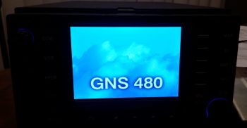
My GPS Navigator choice: GNS480

Although it wasn’t my intention initially, as I dug deeper and deeper into learning the GNS430, curiosity of how its features compared to other units got the best of me.  So during breaks in training I would sneak in quick peeks at the Avidyne and GNS480 features.  As I would Google certain features that I wanted more info on regarding the 430 (holds, OBS, airways, etc.) I kept coming across overwhelmingly positive reviews on those features for the GNS480 [Admittedly from those bubbas flying behind them… to the guys that hadn’t flown the 480s, the report was that the learning curve was ‘too steep,’ the interface ‘too FMS-like,’ and a constant projected fear of no further Garmin support on these units].

As my curiosity deepened, before bed one night I spent a good 45 minutes watching a video specifically on the GNS480 operations.  I was deeply impressed with the power & capability of the GNS480, and every chance I got I would spend a few minutes here and there researching it more.   After a day or so of this, I sent the 480 video to Marco with a good hunch that he’d really like this unit as well (he did!).

If you’ve ever gotten a feel for my modus operandi, it will probably not surprise you that I was already communicating with a number GNS430W sellers in line with my latest 430W plan.  However, there was an oddity playing out during my short-lived quest to acquire a 430W.  First, nearly every seller of every 430W unit that I engaged with turned out to be a scammer.  Moreover, I spent a good week working a promising deal that in the end turned out to be yet another scam.

However, I guess all things work out for a reason, because during the week I was working the potential 430W purchase with what turned out to be yet another scammer (NOTE: nearly every 430W listed on Barnstormers and other sites turned out to be a scam), I was concurrently learning more and more of the GNS480’s capabilities.  Remember, during the majority of this time I was practicing instrument approaches and studying IFR flying. Truth be told, this training was probably the tipping point in my choosing the GNS480 over the GNS430W.  Why?  Well, as I re-flew my recent actual IFR flights and approaches on the respective 480 and 430 simulators side-by-side, the GNS480 clearly had superior capabilities when it came to flying IFR flights and approaches (in my opinion).  [I’ll expound on the specific comparisons in a later post].
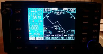
GNS480 Main Map Page

To be clear, with the great price (but not unrealistically low) that I would have paid for the GNS430W that I was dealing on, I would still have gladly bought it and installed it.  My requirements goal here was to install a lower cost WAAS GPS unit that allowed me to fly my Long-EZ IFR.  Nonetheless, by the time I determined that the 430W seller that I was dealing with was a scammer, I reset my search primarily on finding a quality, well-priced GNS480 unit.  Well, in short order I was able to serendipitously do just that, finding a local GNS480 seller (and experienced pilot) that had a unit for sale.
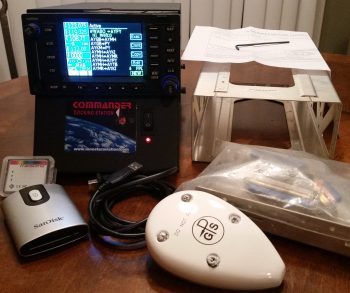
My "new" GNS480 Kit

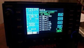
I met with the seller, Phil, at a local airport where I was able to play around with the unit in its Commander docking station.  The fact that Phil was selling an entire Plug-n-play package was the deciding factor in why I pulled the trigger on this unit.  Here are all the components that were included:

  • Garmin checked & software updated to Vers. 2.4 and 5.1 (allows ADS-B+ out)
  • Mounting tray (“tube”), backplate and electrical & coax connectors
  • GA 35 WAAS GPS antenna
  • Data card reader + 2 data cards
  • Lone Star Commander docking station

GNS480 FPL screen...w/ comments!

A result of my evaluation, and subsequent purchase, of the GNS480 has brought me to the conclusion that this will be the final and only GPS unit that I plan on installing in my Long-EZ. Clearly this means that my proposed Avidyne upgrade is simply off the table now.  With the GNS480’s handling of voice and nav comms, its inherent WAAS GPS/VOR/LOC/ILS capabilities, and its fantastic handling of airways, I am more than thrilled to have made my decision final in identifying this GNS480 as Long-EZ N916WP’s long term GPS navigator unit.
 

Chapter 22 – Sloggin’ it out!

Today I started out by finalizing my pitot-static system plan.  I still need to make some phone calls tomorrow to some of system vendors to ensure I’ve got the most optimized configuration for hooking up the pitot-static lines on their respective systems, but beyond that I’m pretty much done.  I’ll be dropping an order to Stein here soon and it will include the remainder of the parts I need to complete my pitot-static system install.

Pitot-Static System

In addition the pitot-static system, I also reviewed & assessed my recently added Triparagon connectors that should allow me to remove the instrument panel fairly easily.  I found a few more issues that made me add the Trio autopilot’s wiring harness to the list of components that require me to simply remove the connector.  The main issue with this harness is that there are shielded wires that run all the way back to the roll servo.  Clearly these are not easily removed, and I’m sticking to Stein’s advice (because I agree!) to NOT add connectors in the middle of shielded wire runs.  Thus, this requires me to remove the Trio autopilot’s connector and leave it in the plane when I remove the instrument panel. In short, I made a lot more progress on the concept of running all the instrument panel components’ wires through connectors to allow EZ removal of the panel.

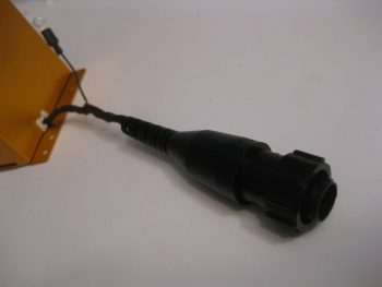
Later on, I figured I would get some wiring done while I was watched football.  Since I had just had the Trio autopilot wiring harness out, I decided to re-terminate the roll servo pins with AMP CPC pins vs Molex, and add the AMP CPC connector housing.  I’m not messing with the pitch servo since it needs to be cut significantly shorter and I need to get a good measurement for that.

Trio autopilot wiring harness

The pic below shows how the connector pins looked before I started.  Again, I cut the Molex pins off and reterminated the wires with AMP CPC pins and then mounted the connector housing for the roll servo cable.

New A/P roll servo AMP CPC connector

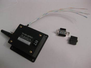
Continuing on, perhaps a little ironically I removed the 9-pin D-Sub connector from the roll TRIM servo and swapped it out with a 4-pin Molex connector I got from Stein.  As you probably know, I’m not a huge fan of Molex connectors, but I figure any roll trim servo failure is fairly benign in the operational realm of flying a Long-EZ.

"Old" Roll TRIM Servo connector

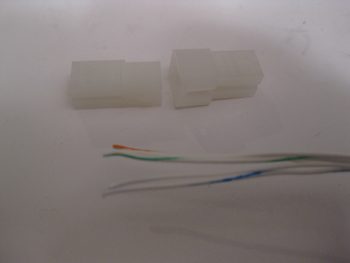
I started by cutting off the D-Sub connector as close to the connector housing as possible.  In both pics above and below you can see the 4-pin Molex connector housing.

Swapping Roll TRIM servo connector

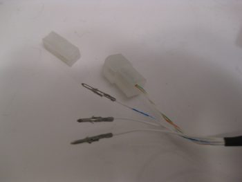
I then reterminated the wires with mini-Molex pins.

New Roll TRIM servo Molex connector pins

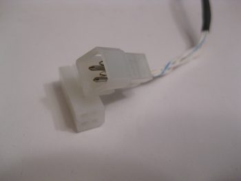
And then snapped the pins in place into the Molex connector housing.  BTW, this connector is J6.  I’ll of course wait to terminate & add wires to the other half of the connector when I actually install the roll trim servo.

New Roll TRIM servo Molex connector

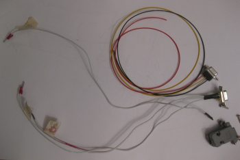
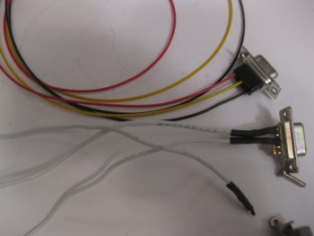
My last action of the evening was to rewire the wiring harness for the TruTrak ADI.  As I was taking inventory of all the wires, which included digging into the manuals, I noted that the wires on the TT ADI’s wiring harness connector were simply HUGE!  Although the installation manual calls out for 22 AWG wiring, these wires range from 14 to 18 gage… way too big!  Since the wires were soldered into the 9-pin D-Sub connector, I simply created an entire new TT ADI wiring harness D-Sub connector with crimped pins.  I of course used 22 AWG wires for the new harness.

Rewiring TruTrak ADI wiring harness

Here’s a closer shot of the new TT ADI wiring harness (red, black & yellow) that will replace the old one (white wires).

Rewiring TruTrak ADI wiring harness

Tomorrow I’ll finish the plan for the wiring, finalize the positions of the airspeed switches and other Triparagon cross shelf mounted components (“CrackerJack parts!”) and attempt to get the Triparagon cross shelf mounted.  I’ll most likely order the pitot-static parts as well after talking to a few equipment vendors.


Chapter 22 – Unraveling the mystery

Over the past few days during the Thanksgiving holiday I’ve actually been getting a fair amount of electrical system documentation, planning & system design work done.  Some things I’ve done, like taking the time out to figure out the wiring & pinouts for the Infinity pilot control stick buttons, switches & wires, is pretty much a known quantity and simply needed to be completed & checked off the to-do list.

Determining P5 connector pinouts

But the pitot-static was a different animal entirely. I had some pieces parts on hand, but I really needed to get educated on pitot-static systems before starting out.  During my research I ran across a very nicely detailed post on the VAF forum from Paul Dye (editor of KitPlanes mag) concerning his pitot-static system.  In the post he not only described his pitot-static system, and the advice that Stein (from SteinAir) –who we know is a genius on all things panel related– gave him, but how he also devised his pitot-static system, and in turn his electrical system, to allow for the panel to be removed EZily.  Hmmm?!

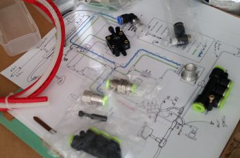
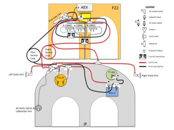
I played around with designing my pitot-static system with the intent to get it documented in PowerPoint and on paper, but have not gotten around to either yet.  Although I pretty much have the pitot-static system designed in chicken-scratch form & in my head, as you can see below (the diagram below was summarily stolen from a guy asking questions on his p-s system that posted it to VAF…I’m merely modifying it to suit my needs!).  But the panel removal idea –one that Marco and I have discussed non-specifically many times– began to gnaw at me more & more each passing day over these past few days.  It was definitely germinating in my brain.  One overriding reason is that if I could pull it off, it could literally change the structure & process of how I build the nose of my plane.

Planning/Configuring pitot-static system

So today I spent the entire day taking inventory and listing out every single wire that comes off the panel mounted avionics, instruments, warning lights, buttons, switches, etc. I determined what connectors would need to stay connected, and which ones must be disconnected for the panel to be removed.  I created a whole new series of connector designators for the D-Sub and Molex series connectors: J1 – Jn, as compared to the current series of the AMP CPC connector series: P1 – Pn.  

After hours of collecting this data, and determining that it could be done, then I got to the business of updating the majority of my electrical diagrams to reflect these new intermediate connectors.  I determined a couple of things, at least initially:

  1. The majority of switches will be on separate sub panels that will be removed from the panel before it is removed.
  2. The Avidyne P1002 communications connector and the Dynon intercom connectors will have to be removed and stay on the plane side due to the multiple cross/inter- connects to components and the shielded wiring.
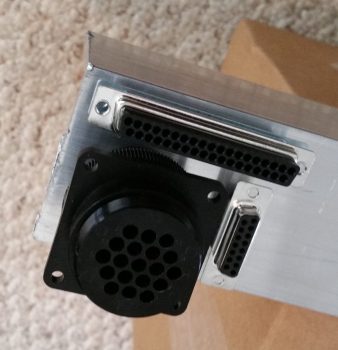
  3. Given the factors above, I determined the number of pins required could be provided with 37-pin (J4) and 15-pin (J3) D-sub connectors, and utilizing the 19-pin AMP CPC connector (P6) that I had previously planned on using for the GIB stick grip.  These should give me enough pins for the panel wiring, with some extra slots.  The AMP CPC (P6) and 15-pin D-Sub (J3) will handle primarily power & ground wires, while the 37-pin D-Sub (J4) will handle primarily signal (a ton of RS232) wires.

Panel removal electrical connectors

Of course I need to confirm and refine my plan, but with this in hand and the finalizing of the pitot-static routing plan, I’ll be able to finalize the component placement on the Triparagon, get the top cross shelf and side mounting tabs cut and lightening holes drilled. I’ll also be able to roll these new factors into the design of the top nose structure and see how it effects the forward canopy skirt.  Tomorrow will be a light build day, but I do plan on getting a few hours more done on this stuff.


Chapter 22 – Electrical System

Of course at this point my electrical system is analogous with the Triparagon.  Since, that being said, it is true too that the majority of my electrical components are mounted, or will be mounted, on the Triparagon.

After spending a good couple of days here & there populating the Triparagon components with wires to & fro the various parts, and finalizing a large number of circuits for the resident things on the Triparagon, it then stood to reason –and begged the question: Does it work?  Yes, it was truly time to test install this monstrosity.

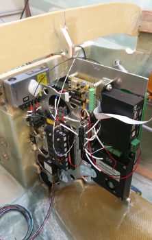
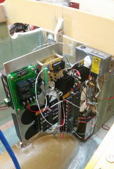
So I did a mock up install of the wired-up Triparagon onto its mounting tabs in what I call the Avionics Bay (instrument panel to F22) of the Long-EZ.  I also installed the Voltage Regulator to see how it fit into the mix.  Below you can see the left side of the Triparagon & the Voltage Regulator.

Triparagon mock install

And a shot of it from the right.  I’d like to point out that up to this point the Triparagon has definitely met, or exceeded, my design goals.

Triparagon mock install

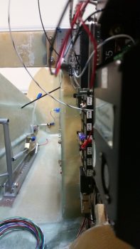
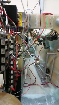
To give you all a sense of space…. specifically the space NOT taken up by the Triparagon (aka “legroom”) I took a couple of shots from close to straight in line with the edge of the the NG30 plates that house the nose gear motor.  In addition, the nose wheel cover (NB) also provides a “natural” barrier & offers a bit of standoff protection from wayward feet or legs to help keep the Triparagon out of accidental harm’s way.  I would like to point out that the current Triparagon wiring is in the initial “free form” stage and has not been organized, nor secured in place yet.

Triparagon mock installTriparagon mock install

There’s still just a bit of cross-connect wiring that needs to be done on the Triparagon proper, along with some final prep of the mounting tabs and the installation of the top cross shelf before I move back onto installing the wheel pants.


Chapter 17/22 – All Electric…

This morning I had to run over to get a new muffler on my truck, which ended up taking half the day.  I went to a cafe and had some coffee while I waited for the truck to get finished, and while there I made up my to-do task sheet for the day.  Unfortunately, I only got the first 2 items on the list done, each of course taking a bit longer than I had anticipated.  By the time early evening rolled around, I punted and simply went to dinner & a movie with a buddy of mine, so not a lot done on the actual build of the plane today.

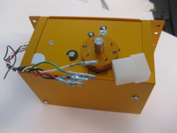
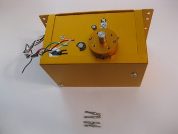
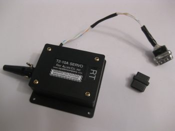
My first task was to prep the connection wiring and replace the connector on the Trio Pro Pilot roll trim servo somewhat like I had done with the pitch servo.  The main difference here though is that the roll servo will reside in the engine compartment, not the cockpit, and thus will be subjected to higher temps and more of the elements.  I wanted to completely protect this wiring and replace the Molex connector with an AMP CPC connector.

Trio AP Roll Servo

I started by removing the Molex connector.

Trio AP Roll Servo Molex pins

And then removed the 4 individual Molex connector pins.

AP roll servo Molex pins removed

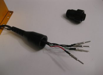
I added a couple of pieces of heat shrink, a flexible wire stay, and crimped 4 new AMP pins onto each of the wires.  Technically, in the same way that as the pitch servo, there are 2 ground wires that share the ground pin connector: one to the internal electronics, and one for the case ground.

AP roll servo AMP pins crimped on

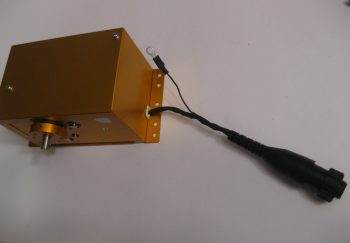
As you can see, I also crimped a ring terminal in place for the case ground wire.  In addition, I snapped each AMP pin into the AMP CPC connector housing and closed it all up.

AP roll servo AMP CPC connector

And a closer shot of the final AMP CPC connector configuration for the Trio Pro Pilot roll servo.

AP roll servo AMP CPC connector

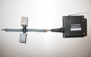
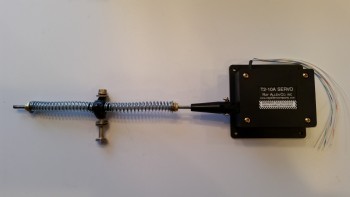
My second (and final) electrical-related task of the day was to terminate the 24AWG wires coming out of the RAC servo that I’m using in my roll trim system.  I decided to try a little trick that Bob Nuckolls has for modifying a DB9 connector to use as an inline type connector.

Below you can see I’ve already removed the metal housing from the female side of the DB9 connector.

Roll trim servo unterminated 24AWG wires

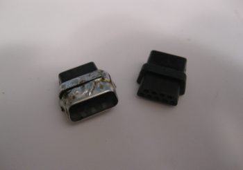
I then had to remove the tabs from the male side, but this being my first time making one of these I removed a bit too much of the flange, so when resoldering the sides back together I had to try to bridge the gap, which if you’ve used solder you know it’s not a good gap filler or bridging material.  I later cleaned off some of this excess solder but pressed on after I took this pic to get this thing completed.

Modified DB9 connector for Roll trim servo

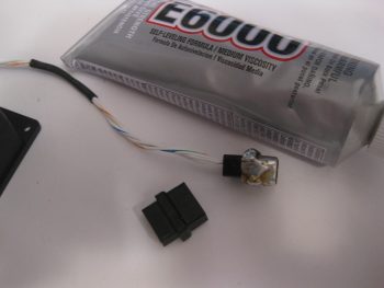
I guess I should have taken an interim pic of the individually terminated wires with the D-sub pins, but here’s the final connector after I added some E6000 adhesive for essentially a potting material & strain relief on the back side of the connector.

Modified DB9 connector for Roll trim servo

The female side of the connector will get D-sub sockets terminated onto the wires and with the wires terminated, all of this will get heat-shrinked together to complete the final connection of the 2 connector halves.

Modified DB9 connector for Roll trim servo

For what is essentially a 4-pin connector I’m not really sure if I’d use one of these again.  I think for the future I’ll look for a more elegant off-the-shelf solution to use for the RAC servo wiring, or any smaller gauged wires for that fact.

I’ll be heading to the AOPA fly-in at the Frederick, MD airport tomorrow, so won’t get anything done until maybe early evening… we’ll see!


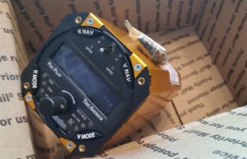
Chapter 22 – Trio Pro Pilot on deck!

Today I finally received one of my instrument panel items that I’ve had on the list of things to buy for years now!  About a week ago I pulled the trigger on the Trio Pro Pilot Autopilot control head.  If you recall, I bought the servos from a guy off of eBay a couple of years ago and had them sent straight to Chuck at Trio who upgraded and ops checked them to ensure all was good.

LEZ Trio Propilot

This autopilot unit has the GPS Steering (GPSS) and GPS Vertical Steering (GPSV) options on it, with the GPSS allowing the Pro Pilot to receive GPSS commands from the GRT EFIS or Garmin via ARINC 429 data outputs.  The GPSV allows the autopilot to receive pitch steering commands from a WAAS GPS receiver for precision approaches using GPS.

In addition, after a lot of discussion over the years, Chuck tweaked one of the pull up resistors in this Pro Pilot’s innards so that it can receive fuel data from the FT-60 Red Cube fuel flow meter along with the GRT EFIS.  This gives me fuel management on both the EFIS and the Pro Pilot, which provides some pretty nifty fuel flow information.


Chapter 16 – New Throttle Handle

The other night I was on the computer when my Spidey sense started tingling, and I started poking around eBay for throttle handles & quadrants.  For some reason I was off on a mental tangent concerning my throttle handle since, if you recall, in early 2013 in response from a discussion with my buddy Marco, I found a source for some F-16 throttle handles for us.  We both like the thought of HOTAS (Hands On Throttle And Stick), and an F-16 throttle handle, besides being cool, obviously offered a way of putting switches on the throttle.

Fast forward a couple of years, with both F-16 throttle & fuselage in hand, I started realizing that the Long-EZ cockpit is just not that big.  Obviously, the F-16 doesn’t have a lot of real estate either, but the Long-EZ specifically has a narrow left-side console & there’s just not a lot of room for a larger throttle handle taking up a lot space in that area.   In addition, the F-16 throttle handle sticks out over the pilot’s leg, which I could see getting in the way during ingress & egress to the bird.

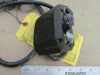
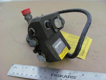
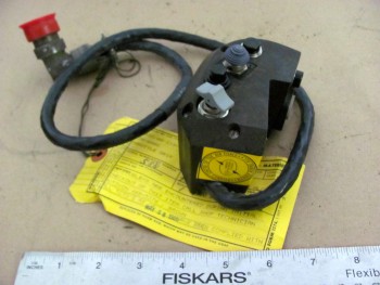
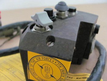
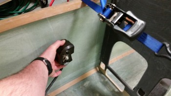
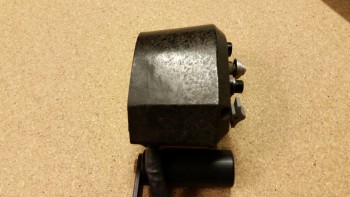
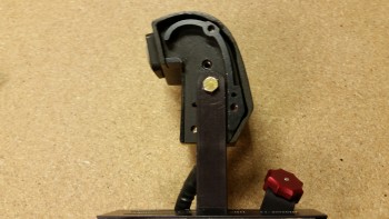
Now, back to my foray on eBay.  I was actually looking for an F-100 style throttle handle, and found a couple when I searched for “throttle quadrants.”  If you haven’t seen an F-100 throttle handle, it’s rather cylindrical with just 3 buttons on the top.  I was actually thinking of incorporating that style into a new design, and maybe work with Marco to build a unique one out of some lightweight 2024 aluminum.  But right before I logged off eBay, I searched for “throttle handle” and found a military surplus F-15 throttle handle for sale.  It was $69 and seemed to be in pretty good shape (pics below).  I did some quick research & felt it was a good deal, so I pulled the trigger.

F-15 Throttle HandleF-15 Throttle HandleF-15 Throttle HandleF-15 Throttle Handle

Once I received it a couple of days later, I pulled it out of the box and quickly checked the size & fit in the cockpit.  The first thing that struck me was the great fit of the throttle handle in the Long-EZ’s fuselage since the throttle handle’s outboard side is completely flat vertically.  This is of course because technically this is just half, or one of, the F-15’s throttle handle assembly.
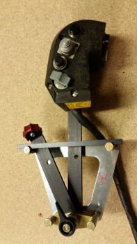
Since the F-15 has two engines, this is actually the right-hand engine’s throttle handle and is located next to the left engine’s throttle handle in the F-15.  If I remember correctly (I supported F-15’s years ago at Langley AFB), they are typically physically paired so they move in unison, thus their mating edges are completely flat . . . which again works perfectly in a Long-EZ!

F-15 Throttle Handle

Curiosity got the best of me so I pulled out the existing throttle quadrant and laid the new F-15 throttle handle next to it.  As you can see from the pic below, the new handle is only slightly wider the existing black plastic tube handle only because of the switches mounted on the side of the F-15 throttle handle.
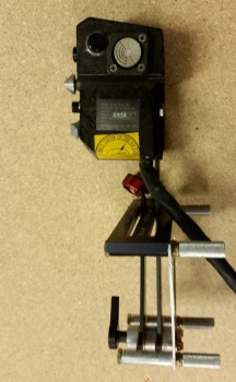
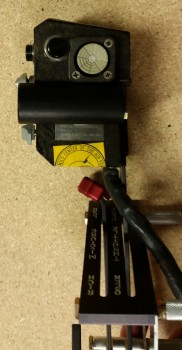
BTW, the cost of those aviation grade switches alone was a big factor in my thoughts on this being a great deal.  Unfortunately, as you can also see in the pics, I’ll have to spend some time on cleaning up the surface of the new handle too if I want to improve its curb appeal (which I will).

F-15 Throttle Handle

Now, every once in a while when I’m off on one my quests to incorporate some unique “unauthorized” modification to my Long-EZ, and am way, way off the path of approved build actions, I actually get a break.  Not just a break, a BIG break that makes something really EZ to incorporate into the design.  Thus, was the case with this throttle handle.

Remember, I had originally just opened the box to ensure that what I had purchased was correct and undamaged.  But after checking the size & fit in the cockpit (GOOD!) and the initial size & fit on the throttle quadrant (GOOD!), I noticed the throttle handle had 3 threaded attach points on the outboard (flat) side of the handle.  These 3 points all were threaded for AN3 (3/16″) bolts, which is exactly what was used to hold the black tubular handle on the the throttle quadrant that I have (AWESOME!)

I quickly took off the existing tubular throttle handle and within mere minutes had the new F-15 throttle handle MOUNTED to the throttle quadrant.  Clearly I’ll have to drill a second hole to finalize the installation, but that will be all that’s required to physically mount this throttle handle.  Of course I will have to contend with routing the wiring as well, but I don’t see that as terribly difficult.

F-15 throttle handle attach

One important note on fit: you’ll notice that with the attach point of the throttle quadrant lever being located close the center of the new throttle handle, the overall space used to employ this throttle handle in the cockpit is quite negligible.  It literally just adds a hair more aft of the original handle, a little over an inch to the front, and the vast difference in height between old & new is minimized by mounting the new handle “low.”  Thus, there’s really only a true height increase of the throttle quadrant by about 1.5″.

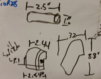
In fact, I keep a small whiteboard on the door of my shop for taking notes, listing glass cut schedules, etc. and I use it constantly throughout my build sessions.  I don’t usually show my chicken scratchings on this blog, but here are the size differences I noted between the two throttle handles:

Old/new throttle handle dimensions

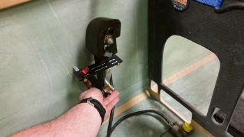
With my NEW throttle QUADRANT assembly in hand, I then checked to see how it looked & fit in the cockpit.  In my opinion, it fits like a glove & is exactly what I was looking for… I couldn’t be happier!

F-15 Throttle Handle

Here’s a side view of the freshly mounted throttle handle.

F-15 Throttle Handle/Quadrant

And a view from front looking aft:

F-15 Throttle Handle/Quadrant

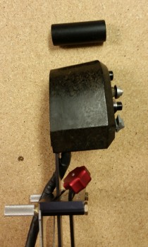
I snapped a few shot to show the size comparison between the old throttle handle & the new one (note the old handle resting on the new one).

F-15 Throttle Handle/Quadrant

And an aft view.

Throttle handle size comparisonsAs you can see, the new F-15 throttle handle fits much better than my existing F-16 throttle handle (I guess I actually didn’t show the F-16 handle, so I’ll try to get a pic of that in a future blog post). It’s a little ironic, because as I mentioned before I actually worked on & supported F-15s while in the Air Force, and although I was trained on F-16s, I was never stationed where I was in direct support of them.

Another point in this handle blowing the F-16 handle out of the contest, is clearly this handle comes with switches mounted!  That makes the task of identifying and employing switches for the landing brake, PTT, COM flip-flop, etc. much easier.  Over the next week, I’ll be identifying the wiring schema for the throttle handle, and figuring out how the handle-mounted switches will be incorporated into the overall electrical system plan.

A quick clerical note, I’ll be posting this both in the Chapter 16 (Controls) & Chapter 23 (Engine) build log sections of this site (the original F-16 throttle handle posts were listed only in the engine chapter).


Chap 17 – Finishing up the Roll Trim

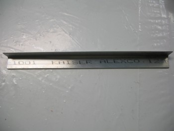
The only I thing I needed to construct to finish up the roll trim as per Waiter’s detailed instructions was the two 1/16″ thick 2024 aluminum angle tabs.  These tabs hold the X-Tube to the control tube (which transits down the side of the fuselage).

I didn’t find any angled 1/16″ 2024 aluminum as I rooted around in all my metal stock, but I had a nagging feeling that I had ordered a piece.  Thus, last night I carved out some time specifically to research the case of the missing angled aluminum (queue dramatic music).  A significant motivation for me to look was that it was going to cost about $17 to have a $3.50 piece of aluminum sent to me from Aircraft Spruce.

First, I found it in on my master spreadsheet and I had even listed it as being for the roll trim build.  That meant that I should have it on hand.  With various parts of my EZ project literally having been scattered about 5 locations around the world, I thought maybe I might have lost it in transit.  Well, I then checked my invoices and found the box that it had been shipped in, along with the aluminum tubing for the fuel lines.  Since it was wrapped in brown paper at the bottom of a tall box, I had missed it at the bottom, dimly lit corner behind & below all the various tubing and wire bundles.

Anyways, an hour blown on looking for my aluminum angle piece, but the mystery was solved & case closed!

Roll trim tab construction

After I finished the aft seat 2-ply BID reinforcement layup and while it was curing (detailed in the post above ↑) I set my sites on knocking out the tabs for the roll trim assembly. This will finish up the actual construction of the roll trim assembly, and all that will be left is the installation & wiring up of the roll trim system.

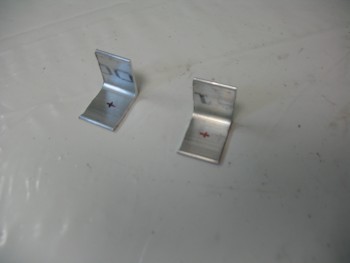
I checked each end of the 1/16″ angled 2024 to ensure it was square, which both sides were. Then after making a mark at 3/4″ I simply used my small chop saw with a wood blade, and very slowly cut the aluminum.  Repeat for the second one and voila!  Two tabs.

As per Waiter’s plans, I marked the spots for the mounting holes in center going top to bottom (3/8″) and 1/2″ from the side (this is 1″ x 1″ angled 2024).

Roll trim tab construction

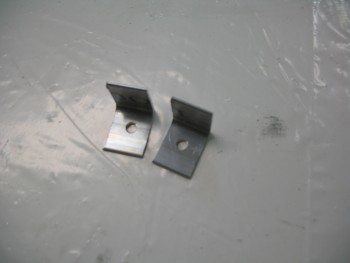
I drilled a small pilot hole in each tab, then finished up with a 3/16″ hole.  I deburred the holes & then checked the fit of the AN3 bolt.

Roll trim tab construction

I then cleaned up the edges with the Dremel Tool and gave the non-drilled side tabs just a bit of a radius where the pipe clamps will be located as they hold the roll trim assemble to the control tube.

I then mounted the tabs to the assembly.  They fit great and everything looks good.  I’ll Alodine these tabs later on when I do another batch of aluminum components.

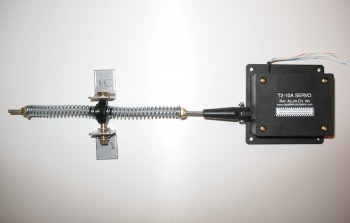
Here’s a few shots with the mounting tabs in varying positions on what I’m going to call the COMPLETED Roll Trim assembly!

Roll Trim Assembly

Roll Trim SystemRoll Trim Assembly


Chap 17 – Roll Trim Complete

Well, let’s say it’s 95% complete.  I still need to cut two 1/16″ 2024 aluminum “L” brackets to attach to the X-Tube (via the 3/16″ bolt) to then be attached to the aileron control tube with a stainless steel hose clamp on each aluminum “L” bracket.  I don’t have any 1/16″ angled aluminum on hand, so I’ll wait until I put in my next consolidated ACS order to pick some up (to save on shipping costs).

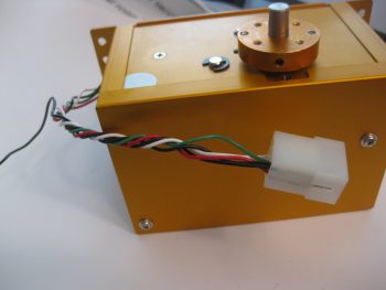
Nonetheless, here is my new, completed Roll Trim system:

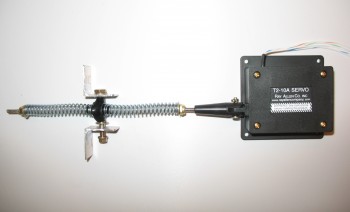
Waiter's Roll Trim