New Canopy Arrives!

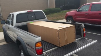
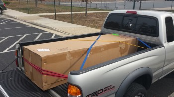
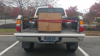
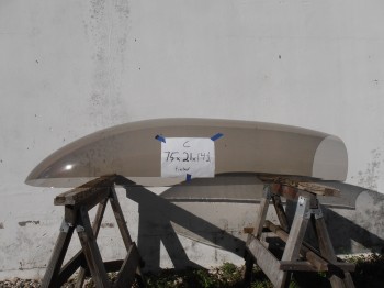
Today I went down to a freight terminal 40 miles south of my house to pick up my new canopy that Todd Silver sent out last week.  Todd had shipped out the canopy in hopes of getting a look at the canopy mocked up on my fuselage when he stopped through town as part of a multi-state canopy install tour that he was on.  Unfortunately, Todd stopped by last night (Tuesday evening), but since I had originally received an estimated delivery for Wednesday (today), that’s when I picked up the canopy.

New Canopy

Canopy - SecuredCanopy - with plate!Canopy Overhead Shot

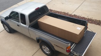
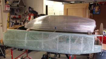
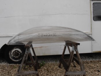
Here’s a shot of the new canopy that Todd had hoped to see!

New Canopy Profile

As you can see by the pic above, the new canopy’s profile is excellent and the dimensions are spot on.  I am VERY happy with this canopy!


Main Landing Gear Fairings

Today I received my Main Landing Gear Fairings from Steve at Eureka CNC.  Although I got a delivery confirmation from FedEX an hour before I got home, the box was nowhere to be found.  Apparently FedEx delivered them to the wrong house, requiring me to go on a 45-minute goose chase for my box.  My neighbors let me know that was a common occurrence so I eventually found them at the house at the end of the street!

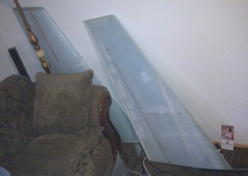
These gear fairings are often called “Wortmann” gear fairings, and as I’m sure most of you know they solve a big drag problem on the Long-EZ by streamlining the main gear in two ways:  First, it takes the oval shape of the main gear and converts it into an airfoil shape, which is exponentially more aerodynamic than virtually any other shape.  Second, it twists the  gear’s angle of incidence so that it meets the oncoming air straight on and fixes the stock gear’s offset profile (read “dirty”) which creates a lot of drag.

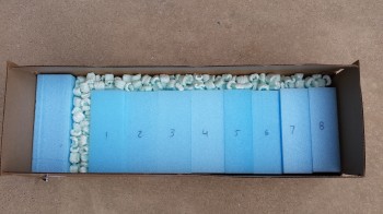
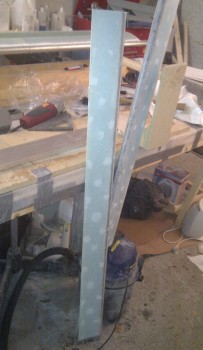
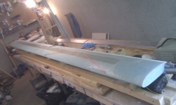
After the delivery drama was over I opened the box to find some very precisely (of course!) hot-wired gear fairings!

Gear Fairings

Eureka CNC Gear Fairings

I can’t wait to get these babies glassed onto the main gear.  Thanks Steve!


New Canopy

I’ve been talking with Todd Silver for a number of months now on getting a new canopy.

Why?  Well, here’s the story:
The first canopy I got from Todd was one that I went down and picked up out of his shop in Ft. Lauderdale in early 2013 while I was deployed to Tampa, FL.  I had wanted a little bit larger/longer canopy so that I wouldn’t have the windscreen up so close to my face, and a little bit taller to have just a little bit more “cabin” space.  However, I should have analyzed the shape of the canopy more thoroughly before throwing it in the back of my vehicle and hauling it back up to Tampa.

Fast-forward to late 2013, once I was settled into my job in Qatar, where I had more time to ponder various build aspects since I wasn’t actually making layups or sniffing epoxy fumes.  I took my pics of the canopy, traced them out (poor man’s CAD) and then overlaid them onto an outline of a close depiction of my fuselage.  I checked this out a number of times from as many angles as I could find.  The main depiction of what I found is here:

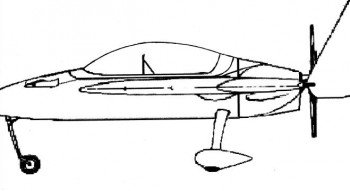
Old CanopyThe canopy profile is very close to a true section of a circle on a standard curve. What this meant is the highest point of the canopy sat behind the rollover structure and really wasn’t adding any usable space, but was most certainly adding drag.  Now, to be clear I picked this canopy out of a lineup and the result of my dissatisfaction with it was my fault, not Todd’s.  Todd was nothing but exceptionally helpful as I was looking at his canopies.  In addition, the shape of the canopy also meant a fairly flat and low profile directly in front of the pilot’s seat, and a sharper curve aft where the canopy met the firewall structure.  To be clear on another point: this canopy is beautiful.  It just happened to have the wrong characteristics that I was looking for.

Now, I confirmed my misgivings with the canopy when I came back to the states for a couple of weeks from Qatar in March 2014.  I hauled the canopy down to my buddy Marco’s shop (since my project–but obviously not my canopy–was in storage) and we trial fitted it on his fuselage.  Now, I widened my fuselage 1.4 inches at the pilot seat, but the rest of the fuselage is widened at the same ratio as the original plans fuselage (except my firewall).  Being more of a maverick, Marco chose to widen his fuselage 2 inches the entire length.  When we put the canopy on his fuselage it displayed and confirmed the characteristics I was concerned about (see pic above), but it also proved to me that the dimensions were just too big, since the canopy was close to being oversized even for Marco’s bigger fuselage.

With confirmation in hand, I approached Todd and let him know my concerns.  I sent him the pic above along with this pic below depicting more of the shape I was looking for (BTW, I used Steve Volovsek’s canopy as a style reference).

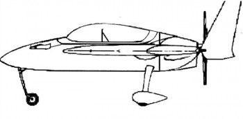
Desired Canopy

As you can see, the most “bubbly”part of the canopy is directly over the pilot as it flattens out behind the pilot for a good intersection angle with the firewall.

Thus began a conversation over the next few months about the size, shape, etc. of the canopy I was wanting.  Since I wasn’t in a hurry to get a new canopy until after I returned from overseas and settled in, Todd and I waited until I got back to finalize my choice of a new canopy.  Well once back, Todd of course delivered in spades.  He sent me a lineup of pics of a few different canopies (I think knowing full well which one I’d pick) that were all very close to what I wanted, with one being spot on:

New Canopy

Compared to my existing canopy on-hand:

My CanopyTodd was a champ and gave me a great deal even though I was the one who initially picked the “wrong” canopy.  Once I picked out my new canopy he shipped it out the same day.


More toys!

Well, after numerous initial discussions with my good OZ-based EZ-building buddy Dave Berenholtz (check out his build log here), the Sky Dynamics engine gurus, and my engine guy Tom, I decided to forego the pain that would ensue if I decided to go with a traditional Slick mag along with my Electroair electronic ignition, and then swap the initially cheaper Slick for a PMag many hours later.  Yes, after Dave so graciously shared his tale of woe as to the difficulty of doing exactly what I had in mind, and after researching the electrical connections required, and the switches, and the  . . . you get the idea.  Much easier to just bite the bullet, design it right the first time, and then get ‘er done with one shot/one kill. [See my 12 May 2014 post]

Thus, being able to fully & justly blame my mate Dave for a much lighter wallet, I called (from Qatar) up Brad at E-Mag back in late May and had a wonderfully enlightening conversation on the myriad of capabilities of the P-Mag system.  Convinced that I was VERY CLOSE to making the right decision, I told Brad I would call him back to pull trigger once I was 100% sure I was going in the right direction and had researched every option. In addition, I knew with Oshkosh looming on the horizon that I would want to put an order in not too far out to ensure that Brad wouldn’t be sold out when I wanted to have a P-Mag on hand.

Well, after some more intense research and another half-dozen discussions with home-builders around the world, I called Brad back a few weeks later and told him that I was completely sold on the P-Mag and would need a unit come late August/early September.

But why did I need a P-Mag then?  Well, I had discussed with my engine builder Tom at Aero Engines in Winchester, VA, that after arriving back in the States I wanted to get the engine built within a month or so.  Although it will be delayed just a bit, within the next month or two I should be building my new ECi IOX-340S under his watchful eye. The PMag was the last major component for the engine build that I needed, and I wanted to make sure that I had it on hand so that an experienced engine builder–knowledgeable on P-Mags–would ensure that I installed it 100% correctly.

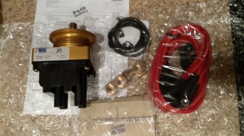
P-MagWell, sure enough Brad gave me a call in late August and my P-Mag unit arrived just a few days later, with a bag of microwave popcorn included no less!  Now that’s customer service!


Chap 23 – Oil Drain Valve

I was putting together my last big Aircraft Spruce order before I left the Middle East to head back to the States and got to the spot where I needed to order my SAF-AIR oil drain valve. I mean everyone uses SAF-AIR right?!  But man, oh man, are these things expensive!  I decided to do a bit more research to see if there were any alternatives out there.  Well, as you all know I spend a lot of time checking out what our RV brethren are doing over on the VAF site.  There I found a bunch of RV’ers singing the praises of an oil drain valve that is used in just about every type, make and model of vehicle around the world… from huge mega dump trucks to Caterpillar tractors to, well, uh, airplanes!

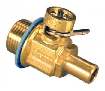
Chap 23 - Fumoto Quick Oil Drain Valve

The valve they were talking about was the Fumoto oil drain valve that carries all the features of the SAF-AIR oil drain valve: it has a quick drain lever and a nipple attachment to allow permanent or temporary mounting of a hose to help in directing the oil flow while draining. It got rave reviews from both the VAF folks, and by just about everyone else that has ever used one. Maybe one of the best features of the Fumoto oil drain valve is the price.  I found it on Amazon for way less than half the price of the equivalent SAF-AIR valve.  Another thing it got high marks on feedback from its users was that it doesn’t leak or drip!

One thing I was concerned about was weight.  Since the Fumoto valve is virtually all brass, while the SAF-AIR is aluminum & stainless steel, my initial thought was that the Fumoto might be significantly heavier.  But much to my surprise (and delight) the Fumoto is almost exactly the same weight (literally within a few grams) as the SAF-AIR valve. With that knowledge in hand I pulled the trigger and ordered my new oil drain valve.  I also ordered one for my truck while I was at it.


Chapter 22 – More Electrical Subsystem Diagrams

As I said in my last post, I’ve been really busy trying to get everything in order to relocate out of the Middle East back to the States.  I’ll be visiting family on the west coast for a couple of weeks when I get back, so I’m trying to set-up all my travels once I get back as well.

I was able to do a fair amount of work on my Electrical Subsystem Diagrams, and I added a few more to the list.  Unfortunately I haven’t had time to take any pics of them.  Here is the new updated list nonetheless:

Z.  Z-13/8 Electrical System
–    Switch Configuration
1.  Panel Components
1.1 Panel Components Power
2.  Radio & audio system
3.  Main Bus
4.  Batt Bus
5.  E-Bus
6.  Nose Gear
7.  Pitch & Roll Trim Systems
8.  Lights: LDG, TAXI, NAV, STROBE
9.  Engine Info Management
10. Fuel System
11. Cockpit Lighting
12. Landing Brake
13. Throttle Switches
14. Control Stick Wiring
15. Integrated Back-up Battery System
16. Alarm & Warning Systems
17. Charging System
18. Heater System
19. Electronic Ignition
20. P-Mag Ignition
21. Component Connections
22. Starting System
23. Panel, Battery & Avionics Grounds
24. Cockpit, Firewall & Engine Grounds
25. Heated Pitot Tube
26. Trio Autopilot
27. ELT
28. Connectors/Pin IDs
30. Long Wire Runs

This will probably be my last update on these Electrical System Subsystems for a while.  I should get back into the swing of things on the build starting early to mid-August when I’m settled back in my house in Northern Virginia.


New Old Pics

Hey Folks!  I found some old pics off my cell phone from Germany and am not quite sure if I posted them previously or not.  Yes, I’m being lazy right now by not going back to look through my myriad of posts to see if they were previously posted or not.  My excuse is that I’m in a mad rush to get everything wrapped up here because I’ll be leaving the Middle East in a few weeks and have a ton of non-build related stuff to get through to get out of here on time in early July.  I’ve got another assignment to the Pentagon and will be heading back to the States sometime in early July.

So here goes.  Some are a bit blurry, but I included them anyway.  Again, these are all build pics from Germany.  A number of them show the assemblies in storage in my Climate Controlled Storage Facility (again, my house… hehe!)

Chap 7 - FuselageChap 11 - Elevators

Chap 10 - Canard

Chaps 19 & 14 - Wings & CS SparChap 20 - Winglets

As oddly as it sounds, I’m going to title the picture below: “Why Microsoft Sucks!”

Normally I use Google Chrome as my browser, but it had uncharacteristically locked up on me, so I opened IE to build this post.  This is the first time I’ve used IE to create a post in probably 6 months.  And I couldn’t even get one post loaded without issues.  I had created this post in it’s entirety, but then when I saved it to go live on my site, it only saved from the first two pics up.  So I guess this post helps support the adage that 40% of work is rework.

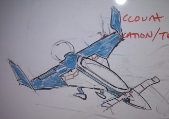
Now, (back on Google Chrome) this pic below is a crude drawing that I made on my whiteboard at work since the folks that worked for me would ask me almost daily as to the progress of the plane building project.  This was long before I built this web site, so I would color in the completed components in blue, and would use this crude diagram to answer any questions they had.  I would guess that this pic was taken circa late August-early September 2012 since the CS Spar wasn’t completed yet.

Long-EZ Build Progress Tracker Cheers!

Speaking of Landing/Taxi Lights . . .

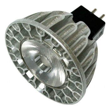
I spoke with electronics guru, Eric Jones, from Perihelion Design for a couple of hours a few days ago.  Eric is a regular contributor to Bob Nuckolls’ Aeroelectric Connection forum.  IMO, two indispensable resources if you’re working your electrical system are Bob Nuckolls’ book, The Aeroelectric Connection, and his forum hosted on the Matt Dralle’s Matronics forums, which covers far more than just electrical systems.  My discussion with Eric turned to LED landing/taxi lights, which he is infinitely familiar with.  I wanted to see if there was a lower cost LED solution to those sold on Aircraft Spruce, Wicks, etc.  Eric recommended the MR16 light, which has many different derivatives, and sent me this specific model pictured below as his recommendation to try out.   As you can see in the pic below, it looks very solid with a robust heat sink & cooling air flow design.

Chap 22 - Soraa LED Landing Light

I bought the Soraa MR16, Model # 00235, which is an 11.5-Watt Dimmable LED light.  In addition, this MR16 is a 75 Watt bulb equivalent with 3700 Candlepower.  It produces a 20° narrow flood beam and looks to be perfect as an ancillary landing/taxi light in the nose along with the AeroLED Sunray Plus LED landing light that I picked up about a week ago.  However, at less than $40 off of Amazon, including shipping, it may just work out to be an excellent deal.  Of course I will test the light, configurations, etc. before incorporating it into my nose light design, but for now it looks highly promising.  I’ll report more on it when I get to that stage of the build.


Chapter 22 – Nose Landing Light

Well, here it goes.  After literally years of wondering, pondering, scheming and hypothesizing as to what I should do for a nose landing light I decided to go with a light that is simple, lightweight, with low power draw … albeit bright.  Notice I didn’t say cheap! 

I finally decided that I didn’t want to mess around with any contraption, mechanical or electro-mechanical device that would move a light from point A into position B so that it could be used to illuminate the runway.  One concern I had with the plans type landing light set-up is that it doesn’t easily allow for incorporating & using wig wag technology… not without some drag penalty.  Over the years I’ve spoke with a number of builders & EZ drivers on this subject, and there is an overwhelming consensus that our Long-EZs are simply difficult to see in the skies, and that we simply need to be as visible as we can possibly get to enhance safety of flight.

Another concern I had was having a single-use light.  I’ve heard many builders, and read many others, discussing having a movable light so that it can be dual-use, serving as both a landing light, then a taxi light.  I really didn’t want to mess around with having to adjust my light to use it as either a landing or taxi light, although I wholeheartedly agree that having the capability for both landing and taxi lights is a valid requirement.

My epiphany finally came from Squadron III’s newsletter, sent out by David Orr (AKA “Beagle”).  Beagle has a beautiful Berkut and guess what he has on the front of it? Two, small, round beautiful lights!  There was my answer!  No drop down lights, no mechanical levers to push or pull, no extra switch to flip . . . the answer was so obvious! Just use two small bright lights, and point one at the appropriate angle for landing, and set the other at the right angle for taxiing . . . or close enough to it.  I’m not overly concerned about the taxi lighting because I have two taxi/wigwag lights designed into the wings.  But by having two small ~2″ lights in the nose it meets all my design criteria: Simple, no moving parts, lightweight, low current draw, minimal drag, and incorporates full-time wig wag capability.

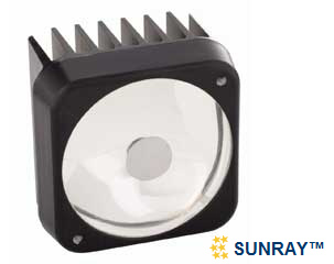
I looked around for a while for an appropriate light to use.  Beagle and I spoke and he gave me some pointers, managing heat being one critical aspect of using nose-mounted landing lights.  I finally decided to stay with my current exterior lighting brand choice by sticking with AeroLEDs.  I ended up buying one of their Sunray Plus LED landing lights.  I figure I’ll test it out & if I like it I’ll simply buy another one to use in tandem.

Sunray Plus


Chapter 22 – Added Sub-System Pages

Before I get into the specific subsystem wiring pages that I’ve completed over the past several days, I wanted to explain my requirement for creating subsystem diagrams for my Wire Book.  Actually, in the spirit of efficiency, and because I think he explains it much more eloquently than I can, I blatantly stole an entry off of Nick Ugolini’s blog that helps expound upon the reasoning of why subsystem diagrams are invaluable tools to have in one’s toolkit when dealing with repairing, upgrading, troubleshooting and diagnosing electrical systems.  Here’s Nick’s sage advice:

The wiring diagrams are absolutely CRITICAL to long term maintenance of the plane and they need to be as complete and clear as possible.   After flying these planes for years, I find most of the maintenance issues in the future will mainly be wiring problems.  Fixing a screw, bushing or engine component is quick and easy.  Finding out why a light or radio stops working is really tough and almost impossible without a well-documented wiring schematic.    The type of connectors, switches, plugs, type of crimper used, wire, etc should be of the highest quality possible, because it will bite you in the butt if you don’t pay really close attending to this critical aspect of the plane.    Of all the work I am doing on the plane, I approach this area with the greatest concern and closest attention to detail possible.    This is why it takes so much time and effort.  I spent 3 hrs yesterday working on just 4 pages of wiring and I am still not done.    I will probably have 30 or 40 drawings.   

Some people approach the electrical draw from the aspect that you should put everything in an area on one page.  An example is the power system should show all components and where they all go (charging, starting, lights, lines to the radios, etc).  This is great for wiring the plane, but doesn’t help as much when you are trouble shooting a sub area of the larger system.  Let’s say you are only working on the alternator part of this system.  

I like drawing the areas out in sub systems.   The alternator system is drawn separately from the starting system or the ignition system.   In the future when you are trouble shooting  problems with the charging system, it is MUCH easier to look at just the system of interest and visually see what is going on.  You don’t have to separate it from a larger drawing with lots of other stuff on it.  It makes wiring the plane more of a pain but is much easier to trace wires.   

Anyone can wire a plane… it is not rocket science and is fairly easy to do.  Run a wire from A to B and you are done. Easy.  I have seen so many planes (certified and experimental) where if you ask the owner for a wiring diagram, you’ll get a blank stare.  I have seen very few wiring diagrams and they were by obsessive compulsive engineer types who really knew the value of having one.   Most builders just wing it.
-Nick Ugolini 

So, with much agreement and in the spirit of Nick’s words, I’m pushing on in my attempt to complete these subsystem wiring diagram pages for my Wire Book.  Since my last post on electrical diagrams I’ve completed the Fuel System, Alarm & Warning Systems, Starting System, and Long Wire Runs wiring diagrams.
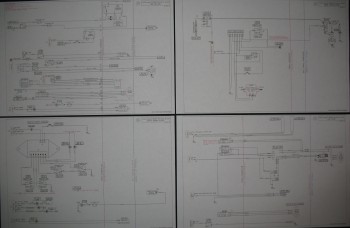
Chap 22 - Electrical Subsystem Diagrams

Here is the fuel subsystem wiring diagram.
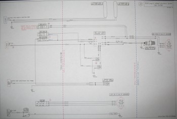
Chap 22 - Fuel Subsystem Diagram

And here is the alarm & warning subsystems diagram.
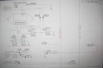
Chap 22 - Alarm Subsystem Diagram

I apologize if the pages look a little slanted, because they are.  I’m using a Brother printer that is supposed to print 11×17 inch pages, and technically it does do that.  However, it just doesn’t print  the pages straight… or it does rarely let’s say.  It sucks, but it was the only one I could grab in my limited time in the States before heading to the Middle East.

BTW, the long wiring runs is nothing more than a pictorial list of all the wiring runs between the nose/instrument panel area and the hell hole/firewall area so I can account for the amount of long wire purchases I may need to make if I don’t already have enough wire on hand.

Below is the updated list that I shared last week (again, green denotes completed or mature, yellow is currently being worked):

Z.  Z-13/8 Electrical System
–    Switch Configuration
1.  Panel Components
2.  Radio & audio system
3.  Main Bus
4.  Batt Bus
5.  E-Bus
6.  Nose Gear
7.  Pitch & Roll Trim Systems
8.  Lights: LDG, TAXI, NAV, STROBE
9.  Engine Info Management
10. Fuel System
11. Cockpit Lighting
12. Landing Brake
13. Throttle Switches
14. Control Stick Wiring
15. Integrated Back-up Battery System
16. Alarm & Warning Systems
17. Charging System
18. Heater System
19. Electronic Ignition
20. P-Mag Ignition
21. Component Interconnects
22. Starting System
23. Panel, Battery & Avionics Grounds
24. Cockpit, Firewall & Engine Grounds
25. Heated Pitot Tube Wiring
26. Trio Autopilot
30. Long Wire Runs