Chapter 16/21/22 – Crossing the Rubicon

Today I crossed the proverbial Rubicon in my initial steps of the thigh support fuel sump by glassing the fuel lines into place, but more about that in just a bit.

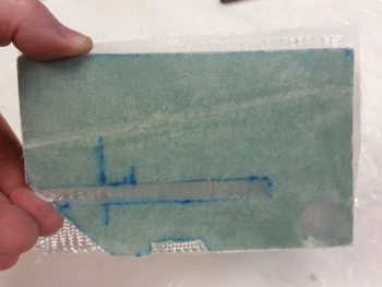
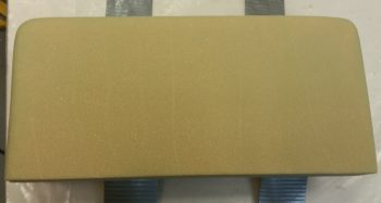
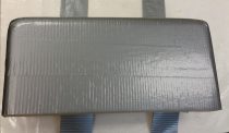
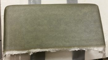
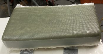
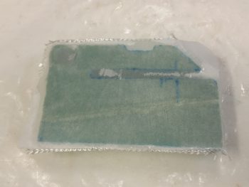
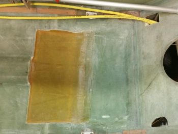
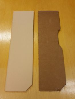
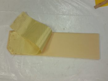
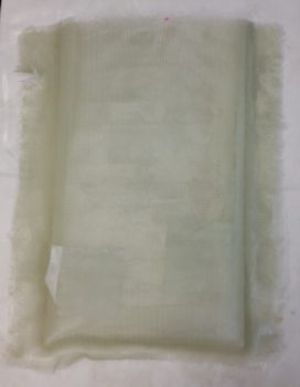
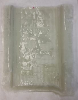
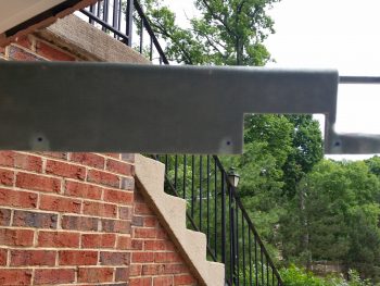
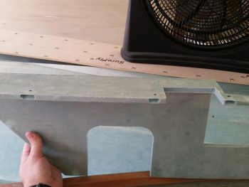
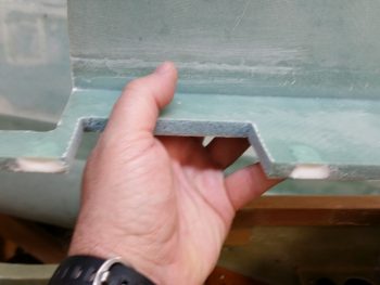
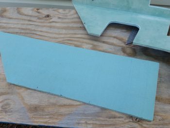
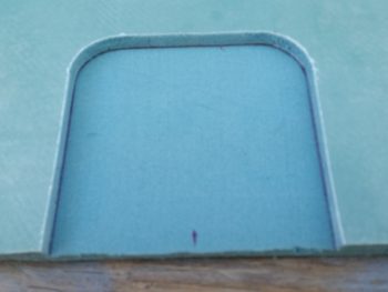
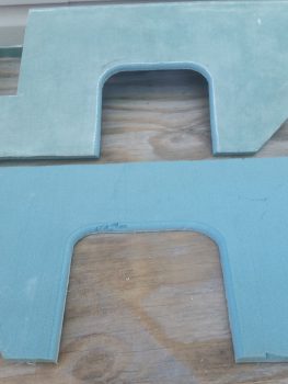
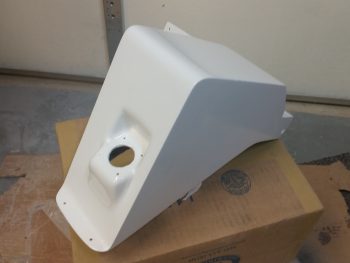
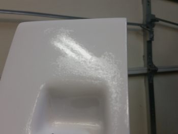
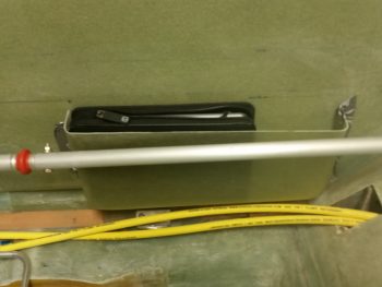
I started out today by trimming up the GIB right armrest storage pocket and removing it from the foam plug.  The pics below show both the front and inside of the storage pocket.

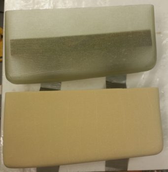
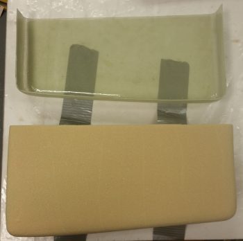
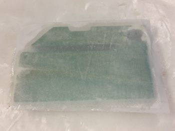
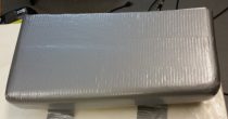
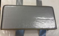
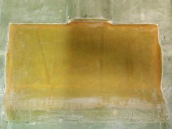
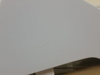
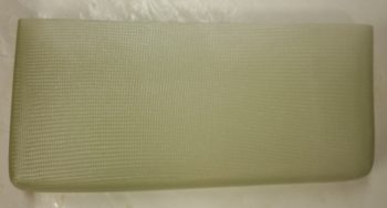
Here it is again, solo.

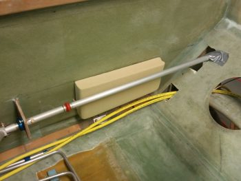
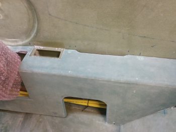
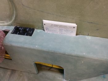
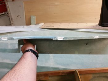
I then mocked it up in place to see how it fit.  I can say I’m happy with it, so it will soon be getting glassed into place so I know exactly how to route all my stuff around it!

I had to lower it about 0.20″ for the iPad to fit, while in its case.  But mounting it just a tad lower also helps me with some lid ideas that I have.

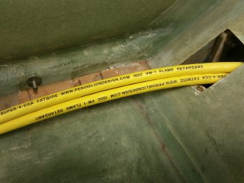
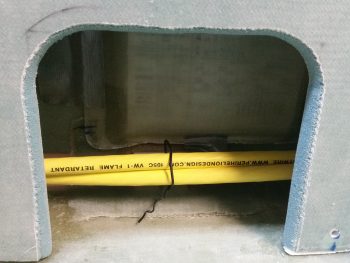
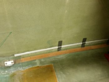
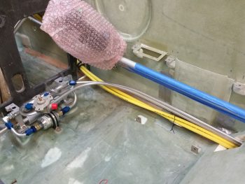
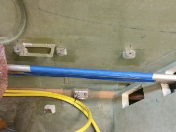
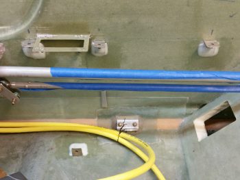
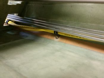
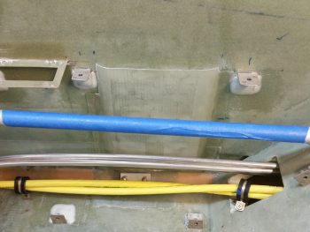
Moving on: I’m happy to report that the big pair of yellow cables are finally secure from the nose to the back seat.  Again, I will most likely have to secure them in one or two places in the Hell Hole, but beyond that, the task of routing these big suckers and securing them is complete!

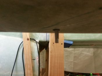
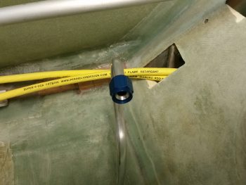
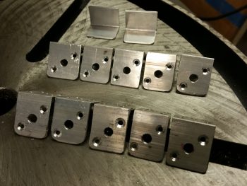
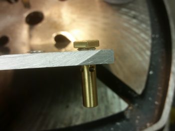
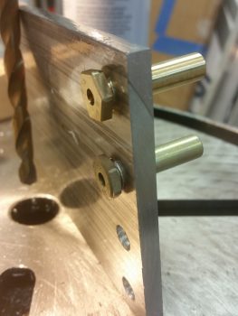
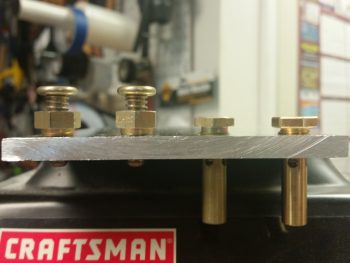
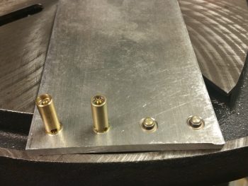
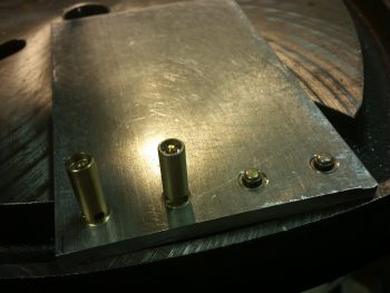
Starting from the front part of the aircraft, here are the two newly mounted Adel clamp hard points in the pilot seat area: one Clickbond (forward) and one RivNut (aft).

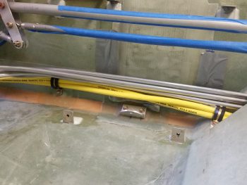
Here’s a closer shot of the Adel clamp Clickbond hardpoint.

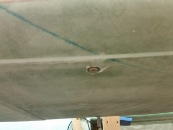
And a closer shot of the Adel clamp RivNut hardpoint.

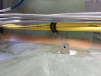
I also mounted a Clickbond just aft of the pilot’s seat as you saw in yesterday’s post.

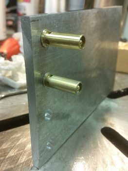
Here’s a clearer shot of that hardpoint with an Adel clamp mounted & in use to keep the big power cables secure.

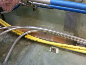
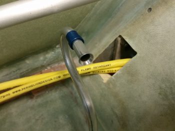
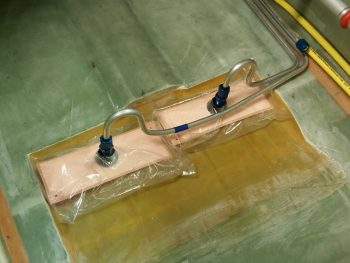
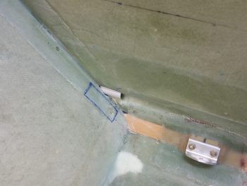
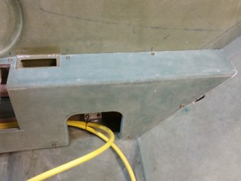
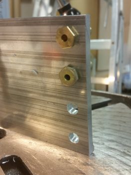
And here’s the RivNut Adel clamp hardpoint in the lower right side opening of the back seat.

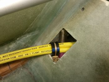
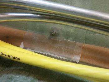
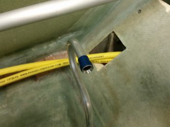
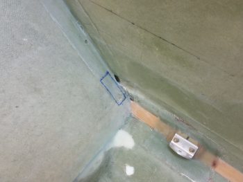
A little wider shot reveals the Clickbond that I floxed in place last night.

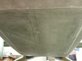
A bit later, I covered the Clickbond addition with 2 plies of BID and some peel ply.

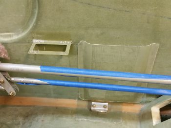
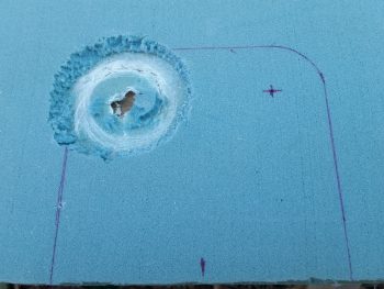
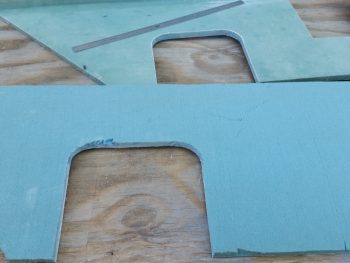
I had an issue with the right side armrest today that needed some cutting to solve.  I simply couldn’t get the armrest mounted since the fuel lines were in the way.  I wanted to be able to mount the armrest since I was going to install the “map” pocket permanently to get a final idea of fuel line routing… and just to get it done!

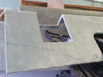
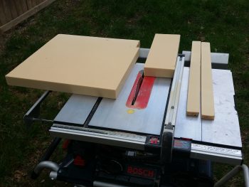
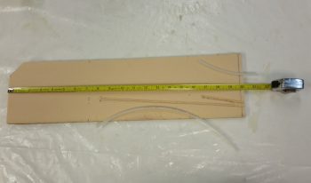
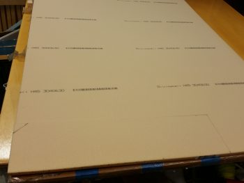
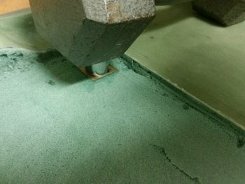
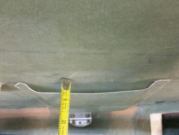
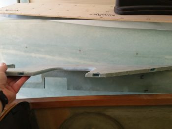
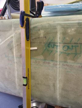
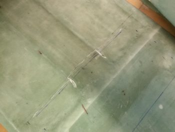
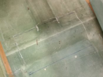
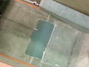
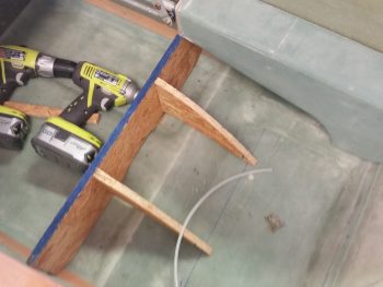
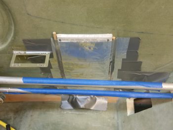
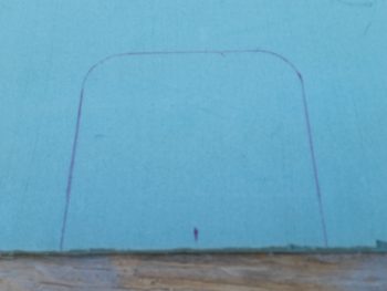
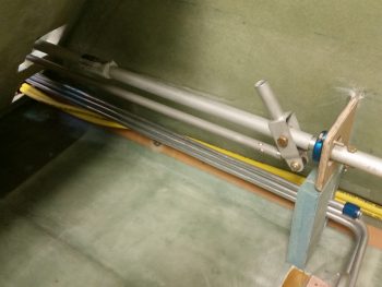
I taped in my 12″ flexible decimal ruler to get a good estimate of what the pilot thigh support ribs profile will be, and then cut it out.  Of course, I also wanted to get this area cut out in my continuing effort to get the pilot area sorted out as well to allow me to move on to the nose build.

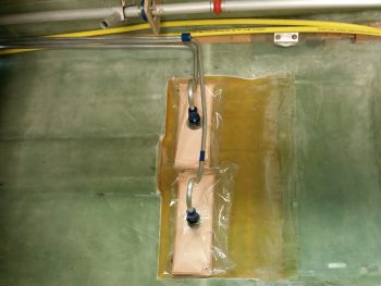
I did flox in the map pocket at this point (final pic is below) during the same round of glassing that I did the big power cables’ “final” Clickbond above.

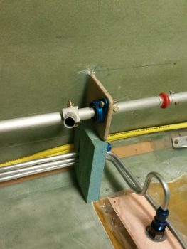
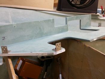
I then moved on with the prep to start glassing the fuel sump right forward wall extension piece to get it installed tonight.  This may seem like not such a big deal, but this piece is a major lynch pin to the entire fuel sump build.  Not only is it a part of the front wall –making the front wall a bulkhead by traversing from one fuselage sidewall to the other– but it also ties the sump to CS118 for added strength.  Finally, it secures the 3 fuel lines heading aft: one to each sump tank and the other to the engine.

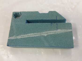
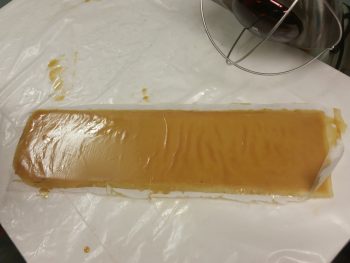
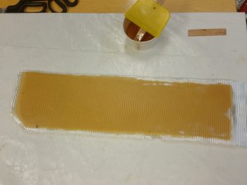
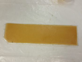
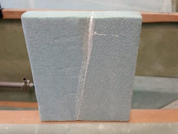
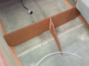
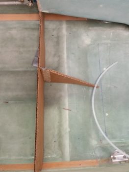
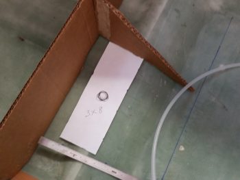
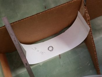
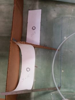
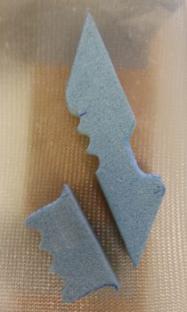
One of my tasks was to make foam fuel line mounting brackets that –at least the bigger one– will need to be glassed in place when the fuel sump right forward wall extension piece gets glassed in.  I’ll most likely wait on the smaller bracket.  If you’re wondering why I went with foam and am using fiberglass to secure the fuel lines, I actually got the idea when I queried Nick Ugolini on it.

To use Adel clamps, I would have had to spread out the fuel lines much farther apart (unless I grouped them together, which was not something I was so keen on doing). Plus, the way the fuel lines go through the pilot seat back opening, they either have to have a significant bend or slant to get them to the sidewall an inch away to use the Adel clamps, or they still need some type of bracket built to provide the required standoff from the sidewall.

Yes, if my “map” pocket wasn’t installed I could have possibly drilled or removed the edge of the pilot seat back that sticks out from the sidewall, but I wouldn’t prefer to do that anyway . . . and of course it’s not an option in this case.  To be clear, I have been researching this topic online and talking to folks for over a week now regarding the securing of fuel lines, and when Nick mentioned this, it was simply an Aha! moment.

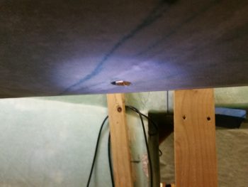
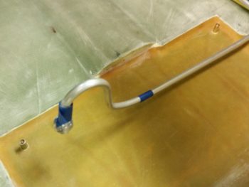
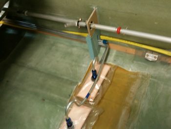
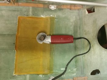
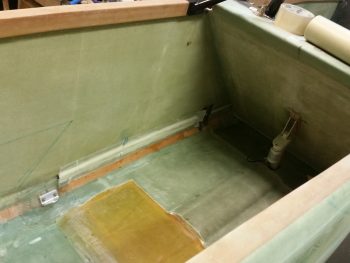
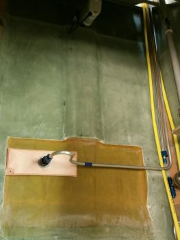
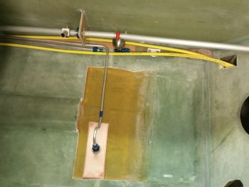
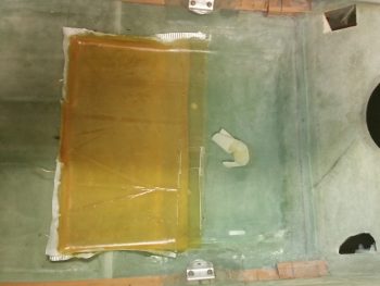
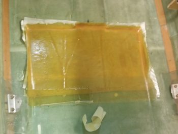
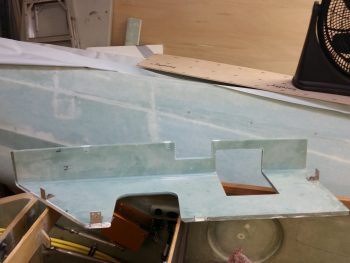
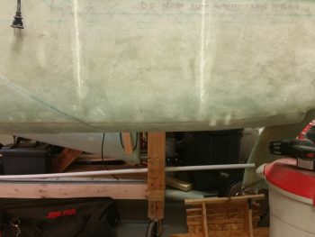
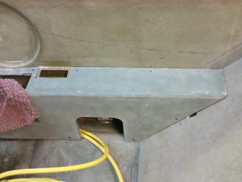
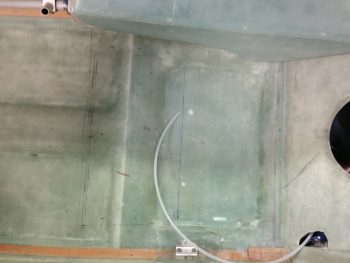
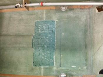
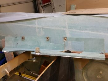
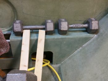
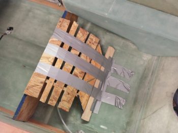
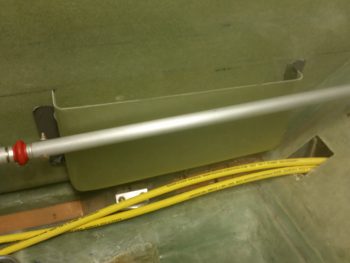
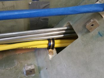
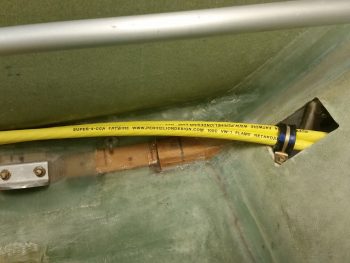
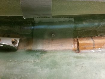
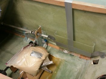
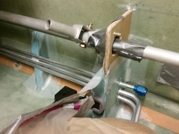
After a grinding few hours, here’s the final glassing-in of the fuel sump right forward wall extension piece. Obviously in the pic you can see where I’ve also 5-min glued the right armrest storage pocket.  As for the sump wall extension piece, I floxed it in place first after sliding the 3 fuel lines into the initial slot I created on this 1″ thick Divinycell extension.  I then used a clamp as a spreader to keep the extension piece firmly pressed against the right sidewall.  A bit later I had to remove the clamp for a bit while I mounted the foam fuel line bracket, but then it went right back into place.

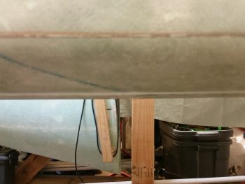
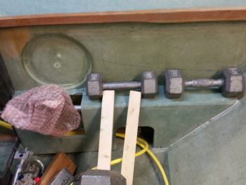
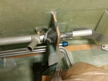
I used a couple of pieces of the original foam I cut out of the wall extension piece to place back under the bottom fuel line.  To lighten up the fuel line install I resorted to using flocro with a bit more micro than flox.  I flocro’d the bottom foam piece back into place under the  bottom fuel line, then had to add another 0.4″ thick foam piece to get the height correct.  I then slathered up the channel for the middle fuel line with flocro and added a 0.35″ foam spacer between the first and second fuel lines.  Again, I added more flocro and then another 0.40″ foam spacer between the middle and top fuel lines. Finally, I closed up the space above the top fuel line with another foam piece flocro’d in place.  The top fuel line has a tad more space between it and the middle fuel line to provide just a bit of clearance for the fitting that’s right there.

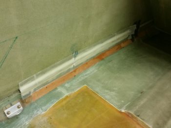
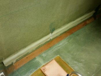
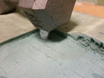
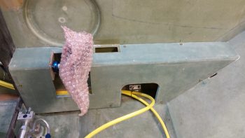
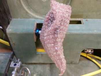
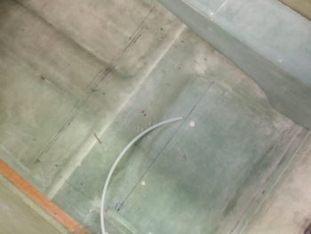
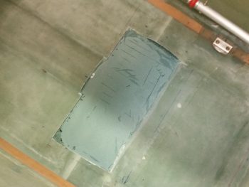
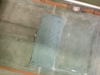
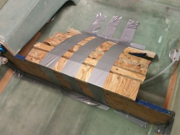
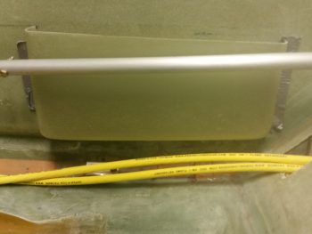
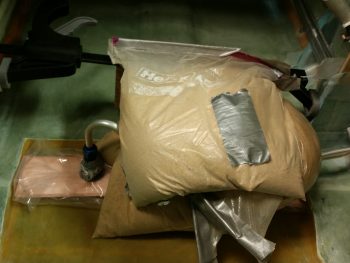
Once I knew the wall extension piece was securely in place, as were the fuel lines, I then carefully used sandbags to weigh down both fuel lines going to the Hydramats in an effort to have them cure in the correct position.  I of course am hoping that there is minimal spring back and that this works . . . to make it easier when mounting the middle and right side walls. Not a huge deal if they don’t, but again, it would make the upcoming wall installations easier.

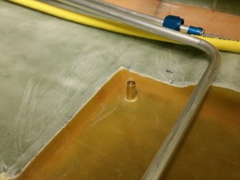
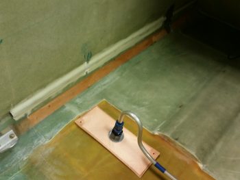
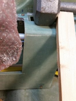
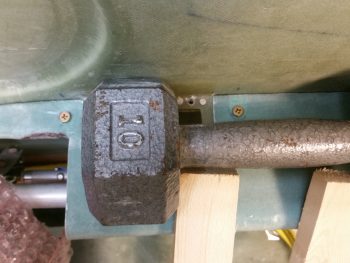
Besides using 2-ply BID tapes to secure the sump wall extension piece to the right sidewall & fuselage floor–respectively, I also laid up 2-ply BID tapes between the CS118 mini-bulkhead and the sump wall extension, also on both the front and aft sides.

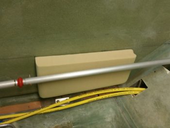
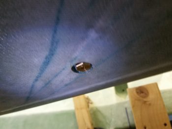
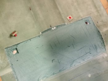
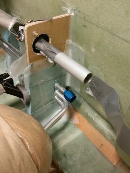
In the pic below you can also see the foam fuel line bracket that I floxed & glassed in place.  For this I simply used 1 ply of BID on each side.  After I ensure the fuel lines are in the correct position, tomorrow I’ll secure each fuel line in place with flox in its respective notch, then I’ll layup a 1″ wide ply of BID over the entire edge of the fuel line bracket, from floor to sidewall.  I’ll most likely mount the other fuel line bracket, and probably even get the fuel lines nice and situated, then mounted at the pilot seat bulkhead opening.

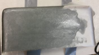
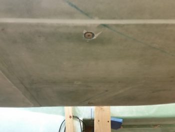
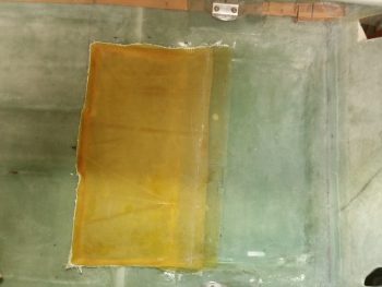
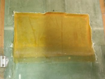
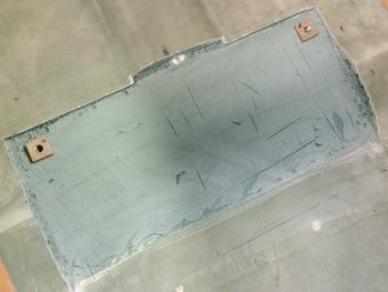
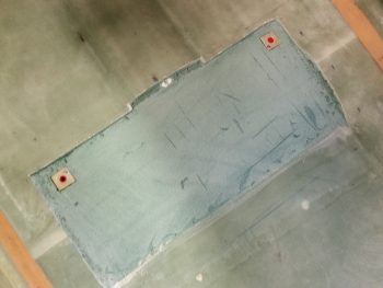
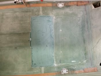
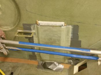
A few hours later after I finished the layups above, here’s the floxed in place and 90% cured pilot right armrest “map” pocket.  I ended up mounting it about 0.050″ lower than I had marked, which actually works out perfectly because there is literally no sign of the actual “map” pocket visible when the armrest is installed.

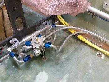
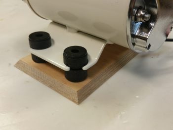
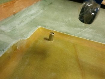
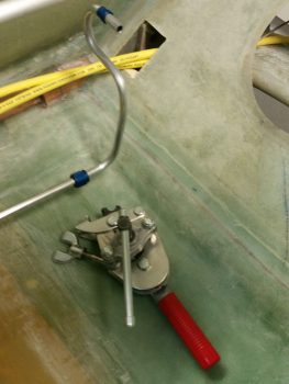
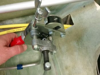
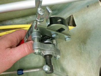
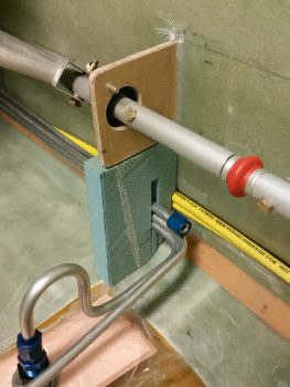
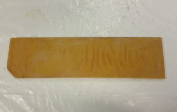
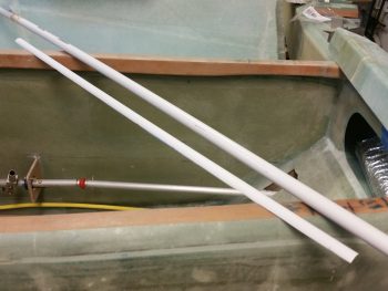
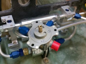
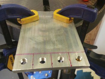
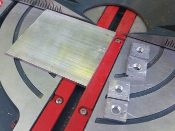
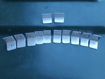
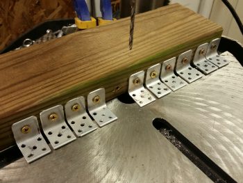
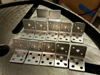
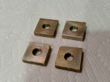
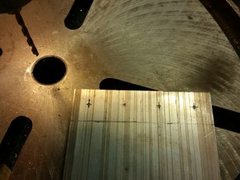
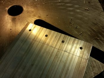
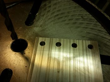
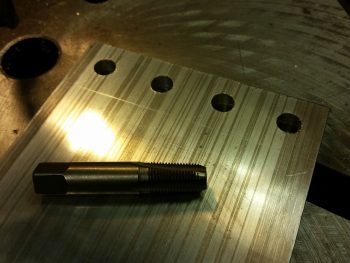
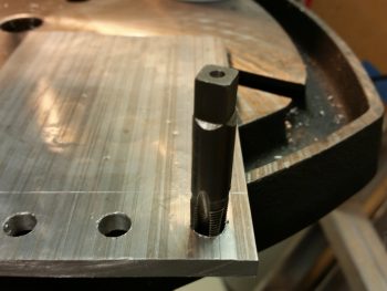
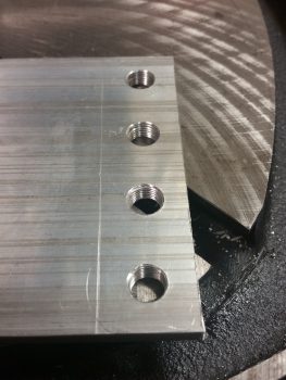
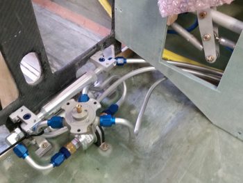
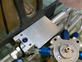
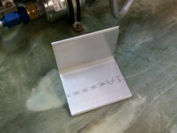
I actually did this early evening before it got too dark, but I placed it here in the blog for better topic flow.  I went out to my shed and pulled out the big miter saw to cut this 2.5″ x 2.5″ x 3″ wide 6061-T6 angled aluminum bracket piece for the initial fuel selector valve bracket.  This bracket will be the base for the “S” curve bracket that will attach to it. In turn, the “S” curve bracket will be what the fuel selector valve actually mounts to.  The position shown here is way low since I just have it setting there.  However, the left/right position shown is pretty much spot on.

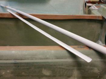
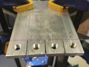
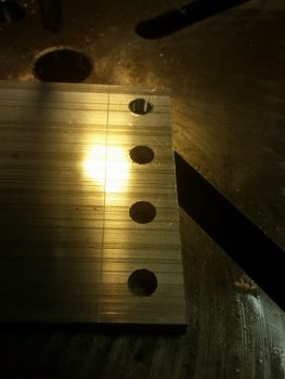
Here’s a shot of it free & clear.

Tomorrow I’ll continue to work on the thigh support fuel sump and should get the front side of the front sump wall glassed, and then actually get the front wall installed tomorrow night.  Then I’ll start working on getting the 2 side walls & 1 interior rib cut out, shaped and glassed.


Chapter 16, 21, 22 – GIB Prereq’s

Today I started out by trimming the right front corner piece of the fuel sump’s front wall extension.  I had glassed the aft side last night, and now I trimmed it up in prep for glassing a ply of BID on the front side.  I did leave the glass over the channel in the middle alone for now just to maintain a little bit more strength in the piece while handling it.

I then micro’d up the foam and laid up 1 ply of BID on the front side.

Something I didn’t mention from last night is that I took the small bit of left over epoxy that I had, whipped up some flox, quickly prepped 2 Clickbonds, and floxed them to the corner of the fuselage in a couple spots to secure the pair of big electrical cables going from nose to aft.  I also embedded a RivNut (not shown) in the pilot seat bulkhead, for an additional Adel clamp for these big battery cables.

So, before I mixed up the epoxy to glass the 1 ply BID layup on the fuel sump right front wall extension piece above (today), I made up two small 2-ply BID pre-preg setups with ~2″ x 2″ plies to secure the Clickbond assemblies that I floxed in place last night using the leftover epoxy.  I laid up a 2″x2″ 2-ply BID layup over the first Clickbond, which is located in the area below the pilot control stick.

Here’s a closer look.

The 2nd Clickbond lies halfway between the pilot seat bulkhead and CS118, aft control assembly mounting mini-bulkhead.  It also got a couple plies of BID.  As you can, I also peel plied both of these Clickbond BID layups.

Still using the same epoxy as the above layups, I whipped up some more flox to attach yet another Clickbond for the big battery cable pair, and also embedded another RivNut in the GIB seat bulkhead for the same purpose.  I know that I’ll need one more Adel clamp in the Hellhole for the big battery cable pair, perhaps two, but that will be it for securing these mondo cables up to where they either attach (-) or pass thru (+) the firewall.

I realized that I was remiss in showing a pic of the fuel selector valve with all the fuel lines in place, so here’s a shot.  Also, to the right you can see one of the new Clickbonds.

I then pulled my table saw out of the shed and cut a 1/4″ thick piece of Finnish Birch plywood for the oil heat pump mounting pad.  I also beveled the edges in prep for it getting glassed into place.

I then tried out the fit of the oil heat pump on its new mounting pad.  The 4 each AN3 bolts will stick through the pad –with the heads embedded in the plywood on the back side– to secure the oil heat pump.  In addition, before I glass all this I’ll sand the beveled edges of the pad to remove any sharp corners.

While I had my table saw out I took the opportunity to cut up some 2″ thick urethane foam for some plugs.  The 2 longer strips on the right will be plugs for the heat & air ducts, while the block in the center is the GIB right armrest storage pocket plug.  FYI – this storage pocket is somewhat like the “map” pocket in the front right pilot’s console, only much bigger.

I hate wasting dead space in this plane, especially since storage space is a premium in Long-EZs.  Since I have just a hair wider back seat bulkhead (around 0.8″), combined with the Cozy Girrrl’s Cozy style control sticks [which straddle the control tube vs. attaching just on the inboard side], I needed to move my control tube assembling inboard about 3/4″ if I wanted the configuration to match that of the plans.  All these minor mods served to create a significant gap between the aft control tube and the right fuselage sidewall.  A gap that I of course exploited to use as storage.

I had jotted down some initial configurations last night, and further dialed those in today to come up with a storage pocket measuring 12.5″ long x 1.7″ wide x 6″ deep (tapering up to 5.2″ deep on the aft side).

This configuration not only provides a fair amount more storage, but it also allows all the engine fuel feed line, main tank sump feed line, big power cables and a smaller electrical bundle to all traverse around or under it.

Thus, with my design good, and wanting to dial in the engine fuel feed line, specifically, I decided to go ahead and glass this baby up.

I started by taping up the urethane foam plug with silver duct tape.  For a smoother interior pocket surface after it has cured, I then followed that up with a layer of clear packing tape.

I used BID as the first ply down, followed up by 2 plies of UNI biased in opposite ~30° directions.  To add a little bit more stiffness than my “map” pocket, I added 1 more ply of BID that covers the entire side and about half of the bottom and each end.

Here’s the glassed GIB right armrest storage pocket.

I then peel plied the bottom, front and back sides to allow for future glassing in place with BID tapes.

I then left it to cure as I went out for the evening.


Chapter 21 – Building sump ‘n stuff

I started off today doing a bunch of research on the Silver Hawk EX fuel injection system to figure out the mechanical lever configurations and how the throttle handle and mixture lever would control the fuel injection servo.  I needed this info to get a good approximation of where the throttle and mixture cables would be run down the fuselage sidewall.  This allowed me to better figure out where my oil lines will go inside the cabin for the oil heat system.

I also did a fair amount of research on the FT-60 “Red Cube” fuel flow sensor installation, as well as the Matronix pulsation damper I have on hand.  Finally, I took a good look and assessed the placement and installation of the oil pump for the heating system.

Upon finally getting back into the shop, I figured it was time to drill out & clean up the currently glassed over fuel sump drain valve hard points.  After carefully drilling the overlying glass and then cleaning up the holes, I then ran the 1/8″ NPT tap back through them to clean them up (although not a great pic, I wanted to show the general task).

I then did a quick install to check how the fuel sump drains looked and felt from both the outside of the fuselage and inside the fuel sump.  Although these are –again– just a quick install to see how the overall fit is and if there are any problems, I’m already very happy with the elevation of the fuel drains.  Once I clear out some more foam and dead flox, they’ll mount even farther up inside the outer skin exterior.

I had to use a light to get a shot of the right fuel sump drain valve.

Here are both drain valves together.  Take note were that green line is next to the left drain valve in the foreground.

And here’s a pic showing a straight elevation shot from the left side of the fuselage looking right.  And what can you see?  If you look at that green line shown in the pic above, you can’t see the drain valves from the side.  And again, these are very initial installs.  Thus, I think the final installs will be exactly what I was looking for.

Here’s a shot of both drain valves protruding up through the fuel sump floor.  I drilled these out now because when the sump walls get installed I figured it would be much more difficult to drill these out & clean them up.

Here’s the right sump fuel drain valve.

And the left sump fuel drain valve.

I spent a good half hour creating a wire template and then bending, shaping and cutting the fuel line that goes from the right sump tank up to the fuel selector valve.  As I was finishing up flaring the front side tube for the AN-6 fitting, I though I should document my flaring the fuel tubing for a fitting, so here it is.

Below you can see the flaring tool ready to go on the aft fuselage floor.  The tubing that I’m going to flare looks like a 3/8″ cobra ready to strike!  In prep for flaring, I taped up the tubing on the front side in the pilot’s seat area to keep it upright.

Here I’ve clamped the tubing into the flaring tool.  For every flare I ensure the cutting edge on the flaring tool gets a small drop of oil.

And here’s after I screwed in the flaring cone into the end of the 3/8″ fuel line tubing.  If you look closely you can see the flared end of the tubing.

And here it is all nice & clean after I removed the flaring tool.

And with the sleeve up nice & snug with the flared tubing.

Finally, here’s the nut in place and the fuel line ready to be installed.

Again, I just flared the right fuel line tubing that connects the Holley Hydramat fuel feed to the right intake on the Andair fuel selector valve.

Here’s another shot of both left & right Holley Hydramats connected to their respective fuel lines.

With all the fuel lines completed (as far I need them to be thus far) I could then configure the front right corner 1″ thick Divinycell foam piece that will make up the right front sump wall extension that actually connects the thigh support fuel sump to the right fuselage wall. I needed the fuel lines to be completed so I could know how to configure them in & through this block of foam.  I also needed to account for the 2 big power cables that weave their way through the length of the fuselage from nose to engine compartment.

As you can see, I cut a groove for the 3 fuel lines and little notch that will allow me to thread the big power cables through this bulkhead later on.  Again, the sump front wall piece that I just glassed will tie into this piece and make up the front sump wall & mini bulkhead across the fuselage at this point.

Moreover, once I configured the right front sump wall extension piece, I was then able to measure the exact length of the fuel sump front wall piece that I had just glassed yesterday, and trim it down a bit.

Also, as you can see in the pic below I made a couple of channels in the foam to run Nylaflow conduits for the sump low fuel alarm sensor wires for each side.

I added a hole in the upper right hand corner of my fuel sump right side wall extension piece for the routing of all the wires heading back to points aft that ARE NOT the 2 big power cables.  I cleaned up the foam and prepped it for a 1-ply BID layup.

After micro’ing the foam surface, I then laid up 1 ply of BID on top and then peel plied it. Tomorrow I’ll do the other side.

In addition, tomorrow I’ll continue to work on the sump and all the prerequisite items that I need to complete to be able to finalize the sump build, and then subsequently the pilot seating area configuration.  Of course this all leads to the final component install in the nose area, which in turn will allow me to finish closing up the top of the nose and get it glassed.


Chapter 16/21/22 – Apollo 13

In the movie “Apollo 13,” Gary Sinise’s character –who was an astronaut left on earth and didn’t go on the mission– is trying to find an optimal way to save as much electrical power as possible for his buddies in their damaged spaceship…getting slung around the moon and heading back to earth.  He tells another character that efficiency they’re looking for can be obtained as long as they get the correct sequence…. and that, my friends, is exactly what I’m trying to do!  Get the right sequencing down in order to be as quick and efficient as possible on this build in the long run.

You may have noted that it seems like I’m all over the map on this build, and I may be a bit.  But what I’m really trying to do is to get all the prerequisites to certain tasks completed so that when the original task is complete, there’s no rework or lost optimization.  That methodology of course entails quite a few rabbit holes that can take hours, days or even a week or so to complete as a prerequisite task for the original task. The original task of course is still there, waiting to be completed, and it will be . . . after the prerequisite tasks are all finished.  I hope that was all clear as mud!

I started off today checking out what was an extremely wet, epoxy-laden layup on the interior side of the fuel sump front wall.

I pulled the peel ply and trimmed the edges.  Not too bad.  I’ll probably leave the epoxy ridges unless they present a problem.

I started off trimming the fuel sump floor layup with my razor knife for a while, then grabbed my “Fein” saw to trim the remaining overhanging glass.

Although it doesn’t look that much different from above, I trimmed all the excess glass away.  As you can see, I also took a few minutes to run the big yellow power cables back to the hellhole.  I need these power cables ran so I can verify the size and shape of the front right side sump tank wall mount, since the front sump tank wall is essentially a bulkhead that goes from one sidewall to the other.

I then needed to figure out my spacing and configuration under the right front armrest for my fuel lines and big power cables, as well as the other smaller wire bundle as well.  To do that, well, guess what?  I needed to mount the map pocket in its position.

So I worked for about a half hour shaping and dialing in the exact spot it would get mounted.  I then transferred the opening shape over to the right armrest, and trimmed a notch in it the size & shape of the map pocket.

Here’s a test fit and a shot at how the map pocket looks with the intercom installed.

And a pic of the lower map pocket and the big power wires heading for the firewall.

Although I hadn’t finished with the right side forward sump wall edge configuration, I wanted to get some glass curing, so I worked on the left side a bit.  The pic below shows a small opening in a slight depression in the side wall at the lower left edge of the pilot’s seat back.  This opening will carry 3-4 antenna cables to the aft fuselage and eventually the wings.  The blue rectangle is where the heating duct will come forward from the oil heat exchange behind the pilot’s seat on the left sidewall.  [The oil heat system is another system that I pretty much just finalized the configuration for.]  So before the fuel sump front wall goes up, there needs to be some accounting of the items that will traverse across the left sidewall edge of the front fuel sump wall.

Additionally, the heating duct that I will be putting in actually needs to be run right over the channel that the antenna cables were meant to go.  Thus, to protect the antenna cables, make them removable, and still keep them in the same place, I cut out about a third of a side of one of my German “PVC” pipes.  These things are really thin, but fairly strong.  I weighed the piece that I used and it came out 0.92 oz.  Not bad.

Here’s a shot of the other side of the piece of pipe that I’ll be using.  I cut it length ways using a utility knife (that’s how thin it is), so it’s not a perfect cut.

After a fair amount of sanding to expand the opening a bit on the lower left side pilot’s seat, I was then able to slide just a peek of the antenna cable channel cover into the opening.  I wanted just enough poking out to feed the antenna cables through.

I taped the antenna cable channel cover to the side wall groove in the GIB area, and then 5 min glued it in place.

Using dry micro, I then covered the depression that ran the length of each side of the antenna cable channel cover (above & below it), which is caused by essentially having a segment of smaller circle sitting inside the segment of a bigger circle.

I then laid up 1 ply of BID in two separate pieces onto the antenna cable channel cover. Installing & glassing this antenna cable channel will allow me to account for it when I mount the fuel sump front wall.

I then started back in on the right side cockpit.  I flared the tubing for an AN fuel line fitting, shaped the engine feed fuel line and ran it off off the fuel boost pump.  I then did the same thing for the left sump tank feed line running it aft from the fuel selector valve.

Here’s a closeup of the fuel selector valve with the left fuel sump feed line freshly attached.

I swapped out the clockable 90° AN fitting for a 45° fitting on the fuel boost pump to get a better exit angle to the sidewall and then aft.

I then spent some time bending and shaping the left sump tank line to get it into place and flared with AN fittings to allow it to connect to the Holley Hyrdamat fuel intake.

In looking at these pics I realized that I should have done a zig or zag with my left fuel sump line to give a little elbow room for the right side fuel sump tank Hydramat.  I’m not too worried since I’m sure I can finagle some space somewhere!

Here’s a shot of the left fuel sump feed line connected to the Holley Hydramat.  Also, you can see the cured antenna cable channel layup in the back as well.

Here’s a closer shot of the glassed antenna cable channel.  I still have maybe a foot left to glass on the forward side, but I wanted to get the lion’s share of this laid up tonight.  With the really dry micro and the lightweight conduit piece, I’d be surprised if this whole antenna cable channel weighs more than a couple of ounces.

Tomorrow I’ll continue figuring out –and laying out– those components that affect the configuration of each side of the fuel sump front wall.  Once those items are complete, I can then best design the openings on each side of the fuel sump front wall/bulkhead, and then glass in the front fuel sump wall.


Chapter 21 – Sump’in’s happening!

I started off today assessing mounting hardware, components and configuration for the FT-60 “Red Cube” fuel flow sensor and the oil heat pump.  I also reviewed my plan & sequencing for the sump build and all the stuff that needs to be mounted in the aft seat area.

Meanwhile, I checked the temp on the curing GIB thigh support fuel sump base glass, which appeared to have held steady at around 125° F all night long.   This was the last check I did before taking off this afternoon to go visit some friends.

Before I left though I grabbed a fresh sheet of 3/8″ Divinycell foam and marked it up to cut out the front wall of the fuel sump.

Here’s a shot of the actual foam piece I’ll be using for the fuel sump front wall piece, next to the highly modified (from initial version) cardboard template.

I then cut 2 plies of BID out (one ply each for the front & aft side, respectively) and a ply of Kevlar for the initial ply on the aft side (interior) of the front wall.

After returning later this evening [including a couple of really good conversations with Nick Ugolini on a myriad of topics], I removed the heat lamps and started pulling the peel ply from the fuel sump base glass layup.

I have to say that at the seam of the peel ply pieces a fair amount of it was a bear to remove.  After some perseverance I finally got the peel ply removed, although I’ll still hit that area with some good sanding to ensure it’s all good.  I also took my razor knife and did an initial trim of the excess glass.

I then started in on glassing the aft side/interior of my fuel sump front wall.  I started by whipping up some E-Z Poxy and then some micro slurry for the foam.  After I got the foam surface micro’d, I then laid up the first ply on the interior sump wall: Kevlar.

I then laid up a ply of BID over the Kevlar.

Here’s a shot of the final 2 ply Kevlar & BID layup fully wetted out & trimmed for the fuel sump front wall interior side.

I then peel plied the layup (no peel ply pic except below) and set it under the heat lamps to cure.  I had a fair little bit of epoxy left, so I slathered it on the top of the peel ply, so this guy was definitely laid up WET!

After I got the glassed front wall piece situated under the heat lamps, I then climbed underneath the fuselage and wrestled something fierce to finally pull the plugs out of the sump fuel drain valve hard points.  I should have done it a lot earlier as the epoxy was at a good green stage, but I forgot so these suckers were in there good.  But again, I prevailed!

Tomorrow I’ll continue to work on the fuel sump, and continue planning out the component installs for the area around the sump.


Chapter 16 & 21 – Arm & fuel

Tonight I started by drilling out the screw mounting holes for the aft 2 brackets on the right armrest.  I then riveted K1000-3 nutplates to the respective brackets.  As you can see, I had already done this for the front bracket last night, but I just didn’t flox it in place yet.

Here’s another shot with the brackets bolted in place and ready to be mounted with flox onto the fuselage.

Again, here are the previous 4 right armrest mounting brackets that I did last night: nicely cured with their 1 ply of BID holding them in place.

With the right front armrest ready to go, I then set my sights on the fuel sump drain valve hard points.  I finalized their mounting locations and marked them up.

Before I got started in earnest on the inside of the fuselage, or moreover, mounted the drain valve hardpoint blocks in place, I needed to cut out a 3/4″ diameter hole in the bottom fuselage glass at each drain valve location.  First, this will allow me to have the bottom skin cut away without any risk of driving a guide bit from a hole saw into the threads of the drain valve hard points.

Also, after the drain valve hardpoint blocks cure in place, I will sand the foam away to expose the majority of the bottom of each block.  At the same time, I will also make a nice radius around each 3/4″ hole so that it transitions nicely with the bottom fuselage skin.  I will then glass in 2 plies of BID onto the bottom face of the drain valve hardpoint block overlapping onto the bottom fuselage foam and finally around the curved edge and onto the bottom fuselage skin.  This will get the drain valves tucked away nicely in case –God forbid– I had a catastrophic main-gear-ripped-off / belly up landing.

In addition, since I have Mike Melvill’s carbon fiber cowlings with armpit air intakes, I will need to fill in the bottom of my aft fuselage as if it had a NACA scoop (because Mike’s did and he filled it up with foam).  Thus, right below the sump tank assembly and around/over the fuel sump drain valve attach divots, I’ll be laying up 1 ply each of Kevlar and BID.  This will of course reinforce and protect both the fuel sumps and these drain valves.

I then finished cutting the foam out of the bottom of the sump tank (left & right) to embed the sump fuel drain valve hardpoint blocks.  I also put plastic red caps into each block to protect the threads from the flox.

Then, not wanting a lot of hard flox & foam stuck to the bottom of each drain valve hardpoint block, I opened up the center hole going through the foam fairly wide.

I then whipped up some flox and mounted the right fuel sump tank drain valve hardpoint.  I weighed it down to ensure the hardpoint and flox were nicely tight and compressed.

I also did the same for the left side.

I then floxed up the mating side of the 3 remaining right armrest mounting brackets and remounted the armrest in place.

I bolted the armrest in place using the 4 mounting brackets that I had previously installed last night.  Here’s a shot of the new forward (against the instrument panel) right armrest mounting bracket . . . well, the bolt head at least.

And a shot of the 2 new lower aft right armrest mounting brackets (right in front of and on the seat bulkhead) bolt heads as well.

Tomorrow my main effort will be on the GIB thigh support fuel sump assembly.  I plan on working that as far as I can over the next few days.


Chapter 21 – Building fuel sumps

I started off today pulling the “map” & document case off the wall.  Thankfully, it came off without too much of a fight.  I quickly pried away the entombed maps, freed them and threw away the ton of tape from this endeavor.

I then inspected it to see how it came out.  It looks pretty good, with some obvious cleaning up required, especially on the inside.

I then pulled the peel ply and trimmed up the “map” & document case and using a couple of pieces of duct tape did a quick mockup on the fuselage sidewall.

I also checked its depth.  In the pic below it’s sitting at about 0.45″ from side wall to “map” case wall.  But remember, there’s tape under the tabs, and I’ll be able to control at least the top depth by the cutout in the right armrest.  The end result is that it should be around 0.4″± ~0.2″.

With the “map” & document case looking ok, I moved on to the right arm rest.  With the “map” case on the side wall I was able to determine where my top armrest screw attach points would be located.  I then determined the rest of the attach points for the right arm rest, except the very top front and very bottom front areas.  These will need special attention based on what kind of stuff traverses these spots.

With my armrest screw attach points known, I used a mounting tab to mark up where the screw hole would be (a very close approximation did fine here).  I then dug the foam out so that when I filled in the resulting divot with 30/70 flocro, I would have a nice hardpoint for each screw to mount into.

Finished with my armrest screw hard points, I vacuumed them out & filled them with flocro using fast hardener (results shown later below).

I then set my sights on the GIB thigh support sump tanks.  My first quest was to ensure that I didn’t damage my embedded brake lines that traverse the bottom of the fuselage, one on each side.  I placed a level along the outside of the fuselage and determined the distance that the brake line was away from the sidewall.  I then marked the inside with an extrapolated, but close, measurement for the brake lines on each side… both using this method.

With knowledge of my brake line locations in hand, I could then more accurately draw out my thigh support sump design on the floor of the back seat.

Just as a point of historical note: these pics below are the last two pics showing the area on the seat pan that I was most proud of . . . and then destroyed!  Such is the way of composite homebuilts eh?

Another quick side note:  To implement my sump design I needed some 1″ Divinycell for a mini-bulkhead in the right front corner of the sump assembly.  Well, I didn’t have 1″ pieces large enough so I micro’d these two pieces together to make this bulkhead piece, which I plan to use in the next few days.

I then put on my mask, drew a big breath, fired up my Fein saw and started cutting! Here’s the front border line of the sump(s) that I started cutting first.

I then cut the interim sides of the sump area.  I moved the cutting lines in about 0.5″ to ensure I didn’t cut into the brake lines.  I’ll then slowly moved my way out to ensure not to damage the brake lines.

I then cut the back line to complete the major glass cutting of this operation.

Then, using a utility knife, I slowly pried off the top glass of my GIB seat glass.

I started removing the foam by hand, but that lasted for about 5 minutes.  This stuff is tough!  I then employed the services of the Fein saw once again and went to town on the foam.

I then employed another power tool: an orbital sander and sanded down all the remaining high tops of the foam.  It did a great job as you can see, but man did it produce some nasty dust…. and a lot of it too.

In the pic below you can see on the right side (top of pic) where I’ve started to remove the foam slowly under the fiberglass, about a half inch in.  This is to ensure –again– that if I hit the brake line, it’s only by hand with a razor knife moving somewhat slowly.  I did not however, encounter the brake lines which should be about where the top/right set of dashed lines are.

Having removed the foam from each side, I then carefully used the Fein saw again the trim away the half inch edge of glass.  I then resanded the edges and in the forward outboard corners as well, which I obviously couldn’t get with the orbital sander.

Here’s a final shot of the freshly contoured GIB seat area ready to be glassed in prep for the thigh support sump build.  You can also see in the pics below & above the marked locations for the sump drains.

After I took this shot, I met a buddy of mine for dinner.

Upon returning home, I checked out the flocro in the right armrest.  Here’s a couple of shots (albeit crappy!).

I then drilled holes into the armrest and riveted up 5 tabs with nutplates.  To limit my variables when installing the armrest, tonight I only floxed in 4 of these 5 mounting tabs (the one at the far right –which is the front side mounting tab– didn’t get floxed tonight).

Not only did I flox 4 of the mounting tabs in place, obviously attached to the right armrest, but I also filled the gap between the armrest and pilot seat bulkhead with micro.  This was planned and I had already placed a long piece of clear plastic tape on the seat in position.

Just a slightly closer shot.

Here’s a shot of two of the armrest mounting tab screws.

And here’s the same one on the left, and another one just to the right of the intercom bracket.

At about 1.5 hours into mounting the right armrest with flox I started prepping 4 x 1-ply BID prepreg setups.  I was checking the flox in the cup and after almost 2 hours had passed I unscrewed the armrest and pulled it free.  With all that micro on the aft side that in itself was a bit of a chore.

Then I whipped up some flocro since I wanted some strength but not a lot of added weight.  With the flox still just slightly tacky (green state) I cut off the flox fingers and covered the tabs with flocro, then laid up a ply of BID over each tab.  I was planning on peel plying these layups, but it’s really late and I’d rather just hit the edges with some sandpaper later on.

I probably won’t layup any glass on the other right armrest mounting tabs and will let the flox just stand for itself.  I did want to get about half of these with a ply of glass on them just for securing the armrest’s sake.

Tomorrow will be a light build day, but over the next few days I do plan on finishing up the thigh support sump assembly as well as the pilot seat area components.  Again, this is all part of the push to be able to have a good assessment, knowledge and fitting of all the nose components.  Once those are in place, I’ll work on finalizing the nose and concurrently knocking out those pesky wheel pants (nope, I haven’t forgot about those!).


Chapter 21 – Collaboration . . .

. . . is the bomb!

I seriously couldn’t have been nearly as effective in building this airplane if it hadn’t been for so many people, but two that I would like to point out to thank specifically are Marco & Dave. They’ve been the source of so many great ideas and wonderful sounding boards for what I’m trying to accomplish here.  Thanks guys!

Now for the post.  First, off I’d like to apologize for the pics.  I’m not really sure what is going on other than my phone camera is struggling, and that’s all I have at my disposal right now.  It either seems in focus at the time, then looks a bit fuzzy later.  Or really just wants to be difficult when it comes to focusing.  I’ll see what I can do, but please bear with these at least passible pics.

Today fairly early on I got my 2 Holley Hydramats delivered.  Again, each of these will go into the sumps that I will glass under the GIB thigh support.

Here’s a shot of them out of the box.  I bought the 3″ x 8″ version.

Here’s yet another device that Dave B. brought to my attention.  These very lightweight Optic-Electrical sensors warn of low fuel levels in the sumps and send that info to my EFIS.

Before heading out of for the afternoon & evening, I cut some scrap wood and mocked up my GIB thigh support sump setup.  I used two ribs only because I was merely trying out the feel of the thigh support.

As I was cutting out the pieces for the thigh support, I wondered to myself what I was going to use as the top of the thigh support, which makes up the seat.  With some scrap wood pieces lying on the ground I realized that I could simply use strips of wood Adirondack chair style and screw them in place.

Here’s another shot of the thigh support sump from the front looking aft.  I have to say this is amazingly more comfortable than the original plans seat.  I did note a couple of minor dimensional tweaks that I’m going to make, but I think my design is good.

After returning home from my social outing, I decided to knock out a fairly quick layup.  I want a thin map-style pocket on the side of both armrests right against the sidewall to hold checklists, documents, and yes, even maps, if need be.  To verify what kind of documents would fit in this area of the side wall, I pulled out an 8-1/2″ x 11″ piece of standard paper, a small binder, maps, a checklist, etc.  I then checked each one to see what would feasibly fit in this area.  After some messing about and pondering each one, I kept coming back to the map size, which of course would easily hold a standard sheet of paper folded in half.  Or a checklist for that matter.

I didn’t want the pocket to be too thick, and was shooting for around 0.370″ deep from side wall out.  I took 3 maps and pressed them together: too thin.  I added a 4th map and it was too thick.  So, I took one of my old maps and cut it in half and that made the pile very close to 0.370″ thick.  To ensure the maps didn’t get messed up, I wrapped them in shipping style plastic wrap, then taped them with clear packing tape.

I was about ready to lay this up on a work board when I realized that the work board is totally flat, but most likely my fuselage sidewall is not.  So, I checked the sidewall and sure enough, it wasn’t totally flat & straight.  Thus, I decided to simply slap this map-packet up on the wall and glass it there.  At first I had some issues with the vertical edges after I duct taped it up on the sidewall. I added the 1/4″ round dowels to help formulate the edge shapes better.  I then covered the hole thing with aluminum foil tape, which helped smooth out a lot of the issues I was having with my duct tape base tape.  I then quickly applied 1 coat of wax to the aluminum foil tape before starting in on cutting out the glass for the layup.

Since I have a ton of spare UNI laying around, I decided to put some of it to good use.  I determined that I needed plies 8.5″ wide x 9.5″ high to cover all the areas with a little extra overhang.  When done, the overhang will get trimmed down, but will provide a mounting edge that will allow me to mount this using RTV (or flox if desired).

The resulting layup schedule I decided on was 2 plies of UNI, biased in opposite 30° directions, and 1 ply of BID.  Now, since the more robust glass should be where the docs are in contact, I put the BID on the interior side, with the 2 plies of UNI on the exterior side.  I then prepregged (big surprise) the whole thing, added a strip of 2″ peel ply along each vertical edge of BID, and then laid this sucker up.

To be clear, with the tape already acting as a barrier, obviously I’m just looking for a good general shape here before I pulled the cured glass of the wall/tape, trim it to good dimensions, then slap it back up using either RTV or flox.

Tomorrow I plan on really focusing on the GIB thigh support sump tank build.


Chapter 16/21/24 – Time, time, time…

Ah, time!  Just never seems to be enough of it… I had an entire 3×5 card covered –both front & back– with tasks that I wanted to complete today.   I got the top 4 completed, with the left armrest wall being the surprise bonus task that I got knocked out . . . read on!

I started off today by marking up the aluminum to cut out the individual hard point blocks for the fuel drain valves.

I had an issue that the only saber saw blade for cutting aluminum that I had on hand was quite dull from the last time I used it.  I cleaned it up as best possible and tried it out since I didn’t want to take time out to go pick up some more.  Well, the blade definitetly wasn’t optimal, but it was just enough to get the job done.

I then pulled out my big miter saw and cut down the line to free all the individual fuel drain valve blocks.

I live in a 3-story townhouse, so I don’t have much room beyond my garage to build.  I have a decent side yard, but most of my big tools are in a couple different sheds since I have no room in the garage for all my stuff.  I say this because when I go through the trouble of pulling a tool out or opening up those sheds, I want to optimize my time by doing whatever tasks I have on the list with the tools available from the shed.  I really do like to consolidate tasks as much as possible because I hate wasting time.

So, with the big miter saw out I cut a bunch of mounting tabs out of 1/16″ 2024 aluminum angle for the right front armrest (a lightweight option idea that I stole from Dave B. after he did all the weight comparisons… thanks Dave!). The tabs are shown further below.

I also pulled out my router table to round over the edges of the lap seatbelt access port.  I had planned on doing this, just as I rounded the bottom edges of both back seat armrests, but again Dave reminded me of it last week so I put it on the short task list. Now, the right armrest seatbelt access was good to go since I widened & squared it a bit last week.  But the left armrest, which is still in individual pieces, I hadn’t touched since 2012 when I cut it out.

I verified & marked the spot of the left seatbelt bracket on the left armrest.  Then I used the right armrest as a template to draw out the seatbelt access port.

I was now ready to cut this baby out!

Well, I tried to use a hole saw as I had with the right side.  The same exact one in fact.  But as soon as the saw blade touched the fiberglass on the back it came off its mount and went absolutely ballistic.  It’s done this a few distinct times before, but usually just a minor ding before.  No worries.  I can assure that this will never happen again with this hole saw because it is no longer with us ( . . . a moment of silent please for the POS hole saw bit).

So, I backed up the aft line about a half inch, upped the top line by about a quarter inch, and cut this sucker out!  Here’s the result below.

I then radiused both left & right armrests using my router table.  As you can see, now just a little bit of extra micro will fill in that gouged foam EZ’ily.

I then cleaned up the right armrest mounting tabs and rounded the corners of the edges that would be protruding out of the wall.  I have to say I’m not a big fan of leaving sharp edges about the airplane so I feel like I’m entering the Gauntlet every time I have to do work or maintenance in the bowels of the plane!

I know there’s a myriad of ways to do this, but I wanted to Alodine these along with the fuel drain valve hardpoint blocks, so I drilled all the necessary holes to flox these to the fuselage sidewall, and mount the nutplates. I started by drilling out the main hole for the screw to go through the tab top into the nutplate.  I then used that hole with sheetrock screws to mount the tabs to the side of a scrap 2×4.  I then drilled the 5 flox anchor holes into the fuselage mounting side of the tabs.

I’ll note that I specifically wanted these tabs a bit narrow, which meant mounting each nutplate at an angle for it to fit.  This angle caused the nutplate center to be pushed out just a hair further from the sidewall by 0.55″ (center of mounting screw).  This is a bit more inboard (off the wall) than I would have wanted, but because of the inside filleted corner on this angled 2024, the screw hole is at most 0.1″ farther out than if I had mounted the nutplate parallel to the corner junction, and/or perpendicular to the side edges.

A final point I’d like to make on this is that my more inboard hole placement also has a benefit in that since I’m not glassing the armrest in (as a structural piece), I am not concerned about it’s strength as a structural aircraft member as per the original plans. Thus, now it becomes simply an armrest, so I will not be adding the second ply of BID to it as I had planned to do when I would install it via glassing it in place (again, 2-plies as per plans).  With only 1 ply of BID on top, the more inboard the screw (away from the wall), the screw has just a bit more meat to bite into for strength (not huge, but every bit helps).

After that, I used a K1000-3 nutplate as a template to drill out all the rivet holes.

I then counter sunk the rivet holes on the top side to allow for a nice flush fit with the inside surface of the right armrest.

I then Alodined all the aluminum parts I created today, except for two.  You’ll not the 2 pieces up at the top in the above pic that aren’t drilled out and that I left blank.  Those are spare 6061 pieces that are narrower in depth, and that I may employ at the very front of the armrest where it intersects the panel.

Here are the Alodined fuel drain valve mounting hard points.

And the right armrest mounting tabs.

Tomorrow I’ll be taking off in the late afternoon for a social event, but I plan on trying to knock out as much as I can on the fuel sump build.


Chapter 13/21/25 – Rogue Paint One

When I noted I didn’t have any pics last night, I failed to mention that I did in fact get something done… albeit not very well!  I clear coated the aft NG30 cover with 3 coats of clear coat, but apparently there was some contamination on the surface because I had some issues.

As you can see on the front, I had a bit of an adhesion problem.

And, to add insult to injury, a nice run on each side.  Ugh.  So, I’ll try to just wet sand it and see if I can buff it out after I wet sand, or I may have to re-clear it.  More to come on this.

With my investigation on my haggard looking NG30 cover complete, I then got to work mocking up the GIB thigh support sump tank assembly, which will include separate left and right sump tanks.

I used cardboard to mock up the forward wall and center rib.  Obviously, this isn’t exact, but my main goal here was to get a general idea of size and dimensions . . .

and check out two different sizes for the Holley Hydramat fuel pickup mats that I decided to purchase for the sump tanks (thanks to my buddy down in Oz, Dave Berenholtz…. I think he owns stock in Holley!).

Why the Hydramats?  Well, the really cool feature for these mats is that as long as any part of it is touched by fuel, it will get it to the fuel pump.  But for me the overriding selling point is the fact that it also pulls double duty as a 15 micron filter.  With Nick Ugolini and other builders warning me of installing filters to catch all the bad fiberglass stuff that will inevitably rear its ugly head, I want that assurance that at the last main point that is composite: the sumps (with of course the composite fuel tanks preceding the sumps), that good filtration for the nasty bits before/as the fuel departs the sumps is occurring.

Since I have both a left and right sump tank, I of course require 2 Holley Hydramats.  Now, these things will work fine bent at an angle, say 90°, so I test fitted the available 3″ x 8″ and 3″ x 15″ versions by using paper templates.  These things aren’t overly cheap, and the latter version is only $10 more, so for almost double the surface I was really trying to make it work.  But, with the internal configuration of my sump, it just didn’t fit well and would be wasted surface area.  Thus, I went with what fit well and pulled the trigger on a pair of 3×8 mats.

Here’s another shot of the 2 sizes in the separate sump tanks.

Moving on.  As I noted last week, I did a fair amount of investigation on my final paint choice for my Long-EZ.  Taking all things into consideration: cost, availability, ease of application, color, workability, and roll on ability, etc., I decided to go with Pettit EZPoxy polyurethane.  Now, com’n!  Seriously?! How can I pass up a paint named “EZPoxy”??

So today I took back a quart of paint to a local marine supply store and traded it in for a quart of top coat and a quart of primer.  A note on the primer:  I will only be priming top side areas for a better looking finish and added UV protection.  And no, again, I will not be flying in primer starting off.

After getting back from the marine supply store, I dropped a small order with ACS for the remaining required fuel system fittings from the firewall forward.  In addition, due to a free shipping special, I also dropped an order with Jamestown Distributors (another marine supply vendor) for the Pettit roll-on thinner, a Pettit topcoat enhancer, and some big Stikit sandpaper for my longboard.

With the acquisition phase of the day complete, I did over an hour’s research on fuel system related topics.  I then went down to the shop and decided to knock out all the 1/4″ 2024 aluminum hard points for both the pair of sump tank fuel drain valves and –while I was at it– the pair of main fuel tank fuel drain valves that exit the front of the strakes.

I marked up my 4″ wide (convenient eh?!) piece of 2024 into 1″ squares.  Then, knowing my Sharpie lines would be gone in 3 seconds after I started, I scribed the lines. I then center punched the crosshair for each hole for a nice starting point for my drilling.

I then drilled subsequently larger holes . . .

Until I finished drilling the holes out for the final diameter required for a 1/8″ NPT Tap: 11/32″.

I then started tapping all the holes in old skool fashion with the tap and a crescent wrench — and of course some cutting fluid.

Yes, I really wish I had a nice tap handle for larger taps, like the one I have for smaller taps because each one of these holes took at least 15 minutes.  Below is a shot of the first hole finished.

I then rounded up my SAF-AIR SA-187 fuel drain valves that will grace the bottom of the fuselage with their presence…. although, to be clear, they are quite shy so must be hidden away somewhat!

I then mounted the first fuel drain valve.  As you can see, I needed the hole just a HAIR deeper since I want these drains to seat very close to the metal hardpoint.

I then mounted my first fuel drain valve to full depth.

Here’s a profile view of the GIB thigh support fuel sump drain valve.

A bit later I finished hole #2 . . . and mouned sump drain valve #2.

After a good bit I finished tapping all the holes with the 1/8″ NPT tap.  I then cleaned up the 2024 aluminum piece in order to test mount all the drain valves.

I then rounded up the pair of main fuel tank drain valves that exit the front of the strakes.

I then mounted all the fuel drain valves that will be on my Long-EZ.

Here’s a profile view of all the fuel drain valves.

And, lastly, an “inside the tank” view of all the fuel drain valves.

Tomorrow I’ll cut all the fuel drain valve hardpoints from the 1/4″ 2024 aluminum plate.  I’ll then continue working on the GIB thigh support sump tanks.  I know it seems a rather circuitous route to get the nose completed, but to really finalize the pilot seat area I need to know the true configuration of the fuel lines. Once I get the sump complete and fuel lines in place, then I’ll knock out the pilot seat area.  In turn, I can then finitely determine component mounting requirements & locations in the nose to prep the nose for getting its top and getting glassed.