Chapter 22 – Pitch trim bracket

A ‘funny’ thing happened to me this morning: Analysis Paralysis!  There is literally SO much to do on getting the interior components and electrical systems emplaced in the nose, that I found myself in the weeds, overwhelmed in which actual direction to charge off into… too many moving parts going on right now!

I decided to focus on getting all the aluminum parts cut that I will need in the near future, and specifically focus on one of the critical completion items on my list before I can move forward with closing up the nose: the actuator assembly install for my Atkinson pitch trim system.

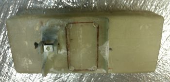
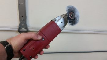
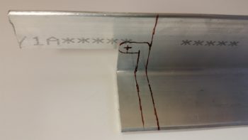
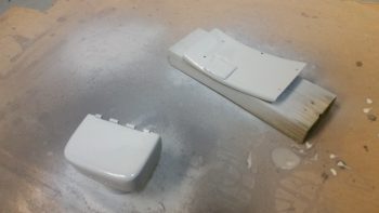
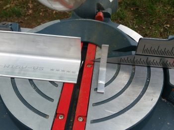
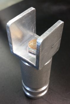
I just got some more 1/8″-thick-sided (1″x1″ overall) 6061 U-channel in from ACS that I ordered earlier this week.  I pulled out the big saw and cut the U-channel 1″ wide to match the diameter of the knurled pitch trim actuator installation hard-point that Marco machined for me (shown below); another fresh bracket lever arm piece for the taxi light actuator (shown getting cut below); a narrow piece of 1/8″ thick 2024 for the other taxi light lever arm; and finally, a somewhat “D” shaped rotating bracket that is the actual attach point for the pitch trim actuator… which gets installed inside the U-channel cut above (all this is shown below as well).

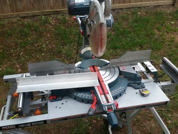
Again, as you can see, these pics show me cutting the bracket lever arm piece for the taxi light actuator.

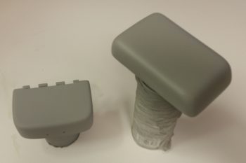
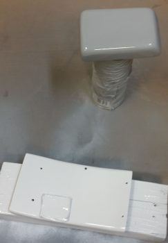
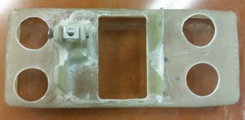
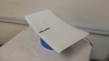
Here’s the U-channel bracket that attaches to the knurled pitch trim actuator installation hard-point.  I ended up scrapping this one and making another one with the locations of both sets of mounting holes dialed in to better fit the tight installation requirements.

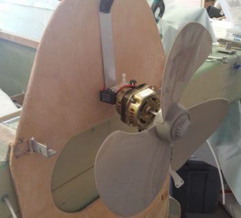
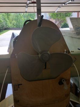
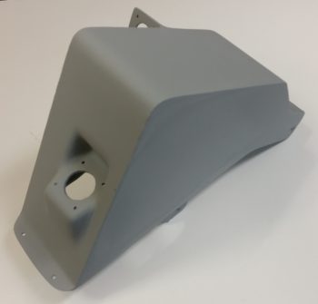
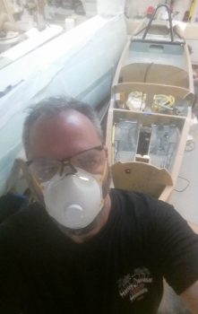
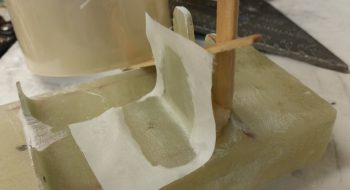
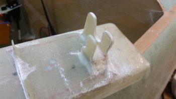
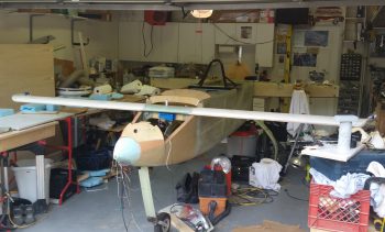
Of course, to figure out the exact installation configuration of the pitch trim actuator, I needed to reinstall the canard.

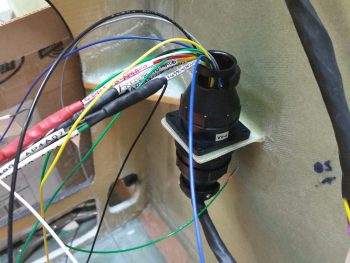
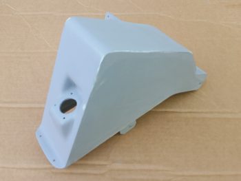
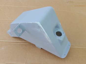
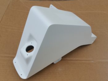
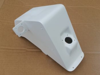
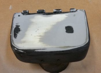
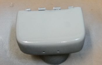
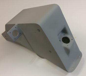
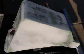
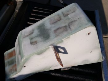
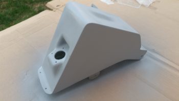
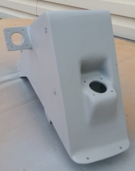
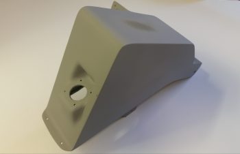
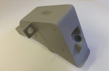
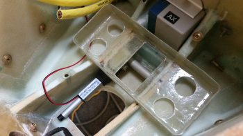
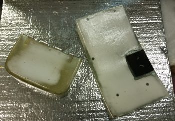
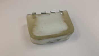
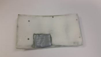
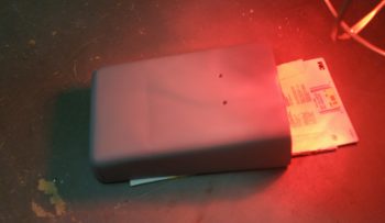
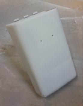
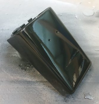
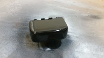
I quickly collected up yet another Marco-made item (thanks Brother!), the Nose Gear AEM box to verify that my dimensions were correct so that it fit in place with the canard installed, and it does.

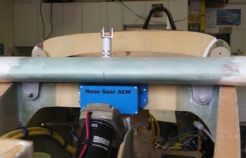
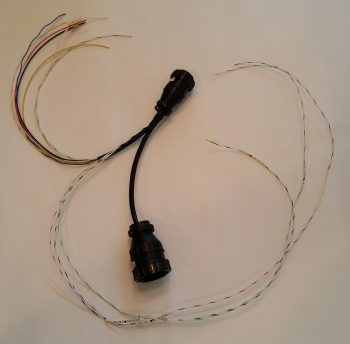
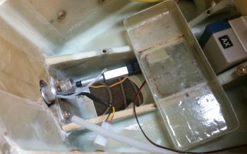
Beyond reconnecting the elevator control tube I also verified clearance between the elevator control arm and the big power cables mounted just below it to the side wall. Again, plenty of clearance with the elevator control arm at its lowest point.

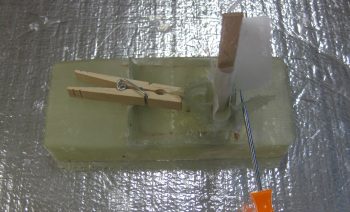
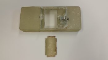
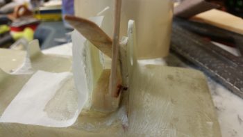
Alas, after spending a fair amount of time dialing in the installation configuration and location for the pitch trim actuator, I finally came to the point where I had to sadly cut Marco’s beautifully machined hard point creation in half.  The side wall where this thing will get installed is simply much narrower than the length of this insert.  I would have chosen to keep the lathed flox grooves on the aft side, but since he could only get the 1/4-28 thread tapped down about 3/4″ of the way into the bolt hole, I did’t want to risk not having enough threads left for a bolt to really bite into.  So, I mounted it into a tight-fitting Adel clamp and carefully cut it on the big saw.

I then spent a good hour+ measuring, drilling, filing, sanding, and finalizing the interior pivot bracket & external mounting bracket that physically attaches the pitch trim actuator to the side wall hard-point mount.

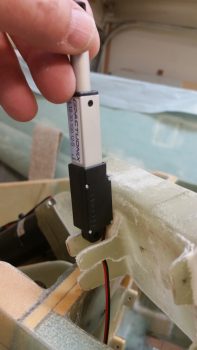
You may have seen that in installations on other builders’ projects that this actuator simple gets mounted with the actuator motor oriented vertically, either up or down.  Unfortunately, if I went actuator motor up, I would need to glass in a bump on my nose to clear it.  If I mounted it actuator motor down, then I would have to contend with it interfering with my right foot while working the rudder/brake pedal.  This all becomes paramount with the understanding that the actuator must be able to pivot side-to-side so that the other end of the pitch trim assembly, which is mounted to the elevator control tube, is allowed to freely pivot with the left-right movement of the control stick.

Thus, I note all this because of the way the physical mounting tab is situated on the pitch trim actuator, in its comparative ease of being mounted vertically, either up or down, which allows for the required side-to-side pivoting action.  However, once mounted with the motor positioned horizontally you could easily realize an up-down pivot action –which isn’t needed or wanted– but not the required side-to-side motion.  Obviously then, I had to account for the actuator mounting tab’s configuration with an intermediate bracket that provides this required side-to-side motion for the now “incorrectly” mounted actuator.

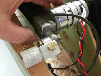
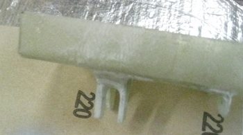
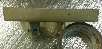
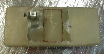
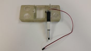
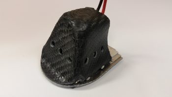
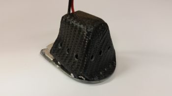
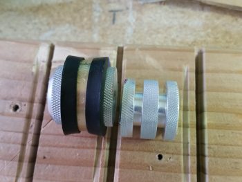
Here’s another shot of the pitch trim mounting bracket assembly.

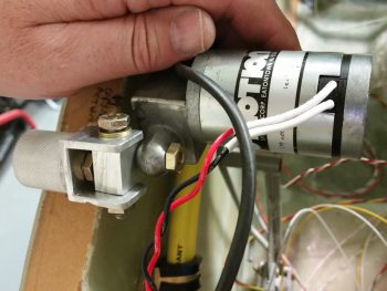
I then detached the pitch trim mounting bracket assembly from the actuator motor mounting tab and snapped a few shots of it at different angles.


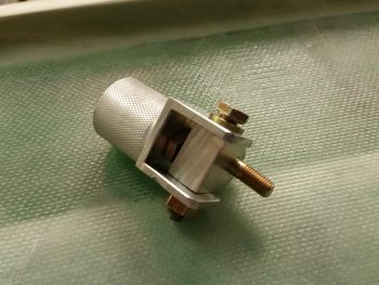
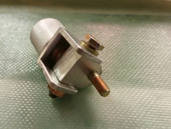
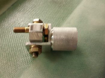
I still need to fine tune the fit & finish of the individual parts, but as you can see, the main configuration design is complete.  And I haven’t noted anything thus far that will preclude this from working as designed.

I’d like to finalize the pitch trim install over the weekend, and move on to other interior nose-located items in prep for closing up the nose.


Chapter 22 – A lighter EZ day . . .

First off, I want to apologize for the first two pics being out of focus.  It’s hard to tell sometimes how they look on the phone screen until later on.  I think there’s plenty enough detail to get the idea of what I’m on about with these pics though.

I started off today wiring up the remaining cavities in the P5 connector, which routes all the wires for the pilot Infinity control stick grip.  The proof is in the pudding when completing these bigger wiring tasks, as so too it is when you finally get down to wiring up these connectors to the end components.  I spent a fair amount of time working over the pinout diagrams beforehand to make sure they were as spot-on as possible, but when the wiring starts –like any best laid plans– things change. Wiring sizes, wiring colors, wire size or color availability on-hand, routing, etc.

In addition, since my new nose gear system is operational, I’ve been scavenging the longer, terminated wires off of the old nose gear wiring harness to use in both the P5 (and P4) connectors.  This changes the wire colors sometimes since re-utilizing good terminated wires that may have a different random color than the first random color I chose is more important to me than sticking to an arbitrary random color!  To be fair, some colors (power & ground) are a bit more sacrosanct to me, but the other random stuff I swap out in a heartbeat.

As you can imagine, there are a lot of rabbit holes to chase down to get all the wiring accounted for in these harnesses.  With the P5 (control stick) and P4 (throttle) connectors being two behemoths in this wiring system, they really do interface with a lot of system end components. For example, although not a jaw-dropping number, if you look at the wires (there’s 3) in the lower left corner of the pic below of the associated Trio Pro Pilot Autopilot wiring harness, one goes to the P4 connector and the other two are terminated together into the P5 connector.  To terminate these wires, a general idea of the routing and a quick mockup is in order to figure out the length. Obviously the length doesn’t have to be perfect, but longer is always better (EZ’er) than shorter.

After figuring out, verifying, and finalizing all the wiring connections, terminations & routing on the P5 connector, I then set my sights on the P4 connector.  It too deals with a myriad of electrical system end components in and around the panel, including Triparagon-mounted items, GNS480 GPS, and even the Landing Brake (see below).  It took me a bit of time to verify the connections on these wires as well, but I confirmed all that was good, and tweaked a few things that had been superseded yet not annotated (by me!).

All in all it was a good day, and I’m really glad to have knocked these two connectors off of the list of prerequisite items that need to get completed before I start on the nose top.  To be certain, in each connector there are a few wires that I actually didn’t mount into the actual connector cavities.  However, I did cut all those wires to length and terminated them, so they are ready to go.  This might help explain why you don’t see the wires wrapped with flightline tape nor any of the cable clamps mounted.

One thing that finalizing the P4 connector wiring above allowed me to do with minimal extra effort was to test out the operations of the Landing Brake using the throttle-mounted landing brake switch.  I haven’t actually run the landing brake in (I think) going on almost 5 years now!  So, to knock some of that rust off . . .  here goes:

I do have about a half dozen connectors to terminate on the end unit side (mostly on the roll trim relay board), which I plan on getting to later tonight or earlier tomorrow.  I’ll also be mounting some Adel clamps and wire-securing hardpoints in the avionics bay (area between the panel and F22) tomorrow as well.


Chap’s 13/22/25 – More wiring & painting

To start out this post right, I thought I’d show you my new environmentally friendly electric engine install with its high efficiency 3-bladed prop (no, NOT a Catto!).

You can see this will save me a ton of weight and I’ll probably be the first Long-EZ that has NO aft CG problem!  HA!

Ok, all kidding aside, I started off today writing out & organizing my required task list for the next couple of days.  I decided to continue the work that Marco and I had started on –the P5 connector (stick grip)– and knock out another 5-6 wires.

One of those wires in that connector is the wire that goes from the taxi light switch to the taxi light actuator relay in the nose (RL011).  I terminated the wire with a pin and then quickly realized that I was supposed to have TWO (2) wires in that pin terminal: 1) one going to relay RL011 and, 2) another going to the “TAXI LIGHT” LED indicator on my panel.

Being cheap and not wanting to waste a pin terminal, I decided that instead of cutting off the pin and reterminating the wire, that I would simply find the point on the wire that I had just run that was physically closest to where the taxi light ON LED indicator would be located.  I then stripped away the insulator on the wire I had just run, cut a new 22AWG brown wire with blue stripe, and solder-spliced it into place.

Since these wires both carry positive current, I covered the solder splice joint with a nice long piece of red shrink tube.

I then decided to terminate the other end of the brown & blue wire with a mini-connector that came with the LED indicator lights.  I realized that I had not finished identifying all the LED indicators, so I took a few minutes to update the info on my panel switches, indicator lights, LEDs, components page.  I then took another 15 minutes, cut up the labels I had printed out quite a while back and labeled each of the LED indicator lights.  With these minute tasks out of the way, I then terminated the brown & blue wire and slipped it into the mini terminal.

I then annotated the wiring label IDs on the new nose gear diagram for the Nose Gear Up Transit and Nose Gear Down Transit LED indicators.  I quickly printed out some labels for those wires, grabbed my stuff and took it all down to the shop to label and terminate these 4 wires.

After I cut these wires (that come out of the P2 connector) to a more workable length, I then labeled each one with the appropriate label [these were peel & stick labels since I’m currently out of the heat shrink labels].  I then terminated a socket onto the end of each wire and mounted them into their respective mini connectors.

I then tested out the gear up transit and gear down transit LED indicator lights as you can see in the very short video below (sorry, I didn’t get a shot of the LED indicator mini terminals).

I then spent a decent amount of time sanding down the perpetual painting project from hell: the nose tool box lid.  This thing has given me an amazing amount of grief in trying to simply get it painted black… to the point of being comical.  I also sanded down the GPS antenna cover that will sit atop the pilot head rest.  It too has presented a fair number of challenges.  I’m hoping over the next week to get these darn things knocked out!

Before I actually started sanding & priming the 2 items above I found about 6 pinholes that had crept back up on the surface of the aft NG30 cover, so I filled those with tiny dabs of Metal Glaze.  I then went on to sand and prime the lid and cover above.

Well, lo and behold there were a few more pinholes that I hadn’t noticed in the shop light, until I took the aft NG30 cover outside. I then whipped up a tiny bit more Metal Glaze and repeated the process (it’s very workable in 20 min, versus the long cure time for epoxy).

Finally, after messing around with the items above for a good bit of time, I was able to do a final EZ sand down of the aft NG30 cover, give it a good bath in Simple Green, and hit it with 3 coats of gloss white paint.

Tomorrow I have another friend coming over, so it may be a very light build day, which is ok because it will allow time for this stuff to cure longer.  I will push forward to finish all my nose-related components, including the electrical system stuff of course, to get them all knocked out so I can move forward on the wheel pants and upper nose build.

Chapter 22 – New Nose Gear System Success!

Hey folks!  I’m happy to report I was able to troubleshoot the issue with the nose gear system wiring.  It turned out to be an intermittent connection on a wire that goes to the down travel limit switch, causing the whole system to lock up in one direction.

Here’s a video showing the gear system tests.  I did the first test solo, then a few hours later I did another one with Marco, who happened to be visiting.

I’m super pleased with how the new nose gear system turned out.  Obviously relieved as well that it works.  Now I can press on with other panel forward tasks in preparing for the upcoming construction & glassing of the top side of the nose.

Chap’s 13/22/25 – A brick wall …

Slogging ‘er out!  Today I did the final sanding on the aft NG30 cover after the final application (hopefully) of Metal Glaze and epoxy wipes to clear up some minor blemishes & pin holes. I sanded down the cover, focused on dialing in the final surface prep for paint. Of course some of underlying filler broke through, but no worries since I hit it with a light colored primer.

I then applied 3 coats of white primer to lock in my surface prep work.  I’m sure there’s a good chance that I’ll have to do some more minor fills, and possibly even another coat of white primer, but as you can see it’s definitely looking more & more polished!

I did a bit more adminstrivia to verify the info I have on hand for my nose gear interfaces & integration with the electrical system.  With minor mods an inherent part of the process, it pays to take a half hour or so to make sure all my diagrams have been updated.

I then proceeded to finalize the wiring on the nose gear RCU P0 connector.  I then went the next step and prepped the main nose gear system power for connection to the E-Bus via a 10 Amp panel-mounted circuit breaker.

I then wired up the Emergency Gear Extend Switch that will be used in conjunction with the 1.2 Amp backup battery to get the gear down in case of an electrical system failure.

After finishing the actions above on the new nose gear system wiring, I took it down to the shop and installed the wiring harness, connectors, AEM box and RCU box into the plane. After double-checking (re-checking!) all the connections and pinouts, I fired up the new nose gear switch.  The gear actuator sprang alive and carried the gear to its fullest down (nose up) travel.  I then moved the gear switch to the up position (nose down) and I was met with only an audible click of the relay in the AEM box.  Hmmm . . .

So, I rechecked all my connections again.  Somehow I missed that I had inserted the big actuator power wires in the P0 connector in reverse… so I promptly fixed that issue.  I reran the gear to see if that fixed the issue and it did not, although it did give me another data point since my new issue was simply now reversed: I could get the gear to go up, but not down.  In addition, I was still met with just the audible click of a relay in the AEM box. I then removed the AEM box and the RCU box, took them upstairs and checked all the connections and circuit routes with a fine-tooth comb.  Nothing.

Thus, I end this evening in perplexed fashion trying to brainstorm on exactly what the issue could be.  Besides the reversed actuator wires that I quickly remedied, I can find nothing askew with the system…. so far.  I’ll work this tomorrow until get this thing going.

BTW, as you can tell, I did NOT get a chance to work on the taxi light extend/retract actuator system.


Chap’s 13/22/25 – Sand-prime-paint, repeat

I started off today by sanding down the top of the tool box lid with a straight sanding board with 80 grit on it.  I took it down until it was level and then hit the top & sides a bit more lightly with 180 grit.  I then washed it up & prepped it for a reapplication of high build primer.

I tossed around the idea of just going back in with paint, but it’s going to need a couple of rounds of TLC for the surface to be ready for paint.  That being said, I just hit it with one medium coat and called it good.

I then spent over 1.5 hours on prepping the aft NG30 cover for final primer.  The top left forward corner and lower left edge where it meets the NG30 plate were both a bit shallow, so I added in some glazing putty to fill it in.  I use the same stuff I did when I was building my custom motorcycle: Evercoat’s Metal Glaze.  It works like a dream… mixes fast and creamy, and fills very smoothly.  It also sands great as well.

I filled one depression on the right side of the cover, and the upper forward corner area on the right as well.

After sanding down the filler and blending it in, I then hit the aft NG30 coat with 2 more coats of primer.

If you look closely, you can see the bleed through of the filler to the surface.  I’ll lightly sand the cover one more time, then most likely hit just these areas again with primer before final paint.  It may seem like I’m being overly fussy, but just like in composites, the prep in painting is really what takes the longest.  The final few coats of base coat (or final here) is the culmination of a lot of prep.  I just want to get this finish dialed into an acceptable level (yes, it doesn’t help that I’ve done body work & painting before… in that I’m sure it makes me a bit more picky) so every time I look at it I don’t get a gnawing feeling that I left a half hour more work on the table to clear up a minor, yet glaring, imperfection.

I was going to use a white primer on both the NG30 covers, then simply clear coat them. However, the primer I picked up was just not bright enough white for me to go on as the final color.  So while I was out I picked up some actual paint (vs primer) and will just go with that, like I did on the tool box.

I then sanded down the boat paint trial application off the GPS antenna cover that will crown my headrest, and also prepped the forward NG30 cover.  I hit the GPS antenna cover with a couple rounds of primer while I final coated the forward NG30 cover with 2 coats of gloss white.  I’m using gloss on a few of the internal nose components (the GPS antenna cover will not get gloss) just to make them pop a bit and stand out from the otherwise mass of matt finish that will be the main finish in the nose compartment and cockpit.

I was doing some research online about Rustoleum paint, and ran across something that made sense to me: since rattle can paint & primer doesn’t incorporate a reducer (like auto paint), it takes a few days to really off-gas and cure to a good point.  I noticed this dynamic on the lower tool box, thus I figured I would leave this stuff alone for at least 24-30 hours before working on it again.

I set my sights back on my new nose gear wiring since the diagram was full of chicken scratches, notes, marker highlights, etc.  One task that really needed to get completed was the deconfliction of P1 connector pinouts.  You see, when I rewickered Jack’s original Molex connector and rewired the nose gear system through an AMP CPC connector for P1, I changed the pinout numbers.  When Marc Zeitlin released his wiring diagram, he logically used Jack’s original pinout numbers.  When I redrew the new wiring diagram, and merged Jack’s and Marc’s systems, I used the original connector pinout numbers instead of mine. This required me to go back tonight and re-label the P1 connector on the diagram with my pinout numbers vs Jacks, since I’m not going to pull the gear actuator side (B side) of the P1 connector apart to re-terminate it.  It also required me to pull and re-pin the P1 connector (A side) terminals using the correct numbers.

However, I did build and add a jumper wire to pins 2 & 8 to allow me to use the P1 connector for routing of a ground wire coming out of the RCU.  Doing this simply cleaned up the wire bundle and actually streamlined the wire routing.

I then soldered two 22AWG wires close to the terminal pin on each of the actuator motor power wires on the P1-A connector for the gear up & down transit LED indicators.  After I soldered the wires in place I heat shrank the soldered joints to secure the wires & junction. I then finalized the A side of the P1 AMP CPC connector, covered the wires that traverse to the RCU’s P0 connector with a mesh cover, cut the remaining wires that will terminate into the P2 connector (upper left in pic below) to length and then snapped a shot of it all.

Along with the main nose gear wiring diagram, I also updated the P0, P1 and J9 connector pinout diagram pages.  Tomorrow I plan on working on the taxi light actuator extend & retract mechanism to get that knocked out.


Chapter 13/25 – New age art . . . ?

Or pinholes?  Ahh, it’s the latter my friends!

I have to admit when I first pulled these pics up on my phone I was wondering what the heck I had taken a picture of…

But, alas, since I sanded down through the actual epoxy wipes into the micro layer on each side of the cover in its never-ending contouring cycle, I created (or uncovered) some pin holes… which of course is the main things the epoxy wipes eliminate.

So, before doing some electrical diagram administrivia this morning, I did some quick epoxy wipes in a few targeted areas on the aft NG30 cover.  Like I had stated before, today will be a light build day, so this will be all I have to report.


Chapter 13/25 – Primed aft NG30 cover

Although I didn’t get a lot done today I think it was fairly significant.  I started off by sanding the entire aft NG30 cover down in preparation for priming.  That was nearly an hour effort in and of itself.  It’s interesting how “straight” these components can look to the naked eye, but once you apply micro and sand it down, then even the subsequent sanding after a few coats of epoxy, you see how off it was from the beginning.  No worries of course because that’s exactly what the finishing process is all about.

After I sanded it, I washed it down with Simple Green and set it outside on my truck tailgate in the sun to dry thoroughly.

I then took the aft NG30 cover around to my side yard and hit it with 3 coats of primer.

Here’s a couple more shots after I brought it back into the garage.

I then wet sanded the tool box lid with some 500 grit sandpaper.  It looked like all the imperfections were gone, so I cleaned it up, and printed out a label for it (which I mistakenly roughed up just barely with the 500 grit sandpaper).

Labels are notoriously difficult to clear coat, so I misted it a couple of times before hitting it with a full application of clear coat.

However, I think unlike the regular Rustoleum paint with its “few minutes” between coats, the clear coat has a quicker flash time in between coats (my current guess, but I’ll have to research more) because what started out as minor workable orange peeling turned into cracks that would put those in the Gobi Desert to shame!  In short, adding the label and clear coat Round 1 was a GIANT FAIL!

Ok, lessons learned and back to the drawing board . . .

Tomorrow I’ll try to epoxy wipe some pin holes on the aft NG30 cover before heading out to my EAA meeting.   But besides that, it will be a light build day since mid-afternoon on I’ll be hanging out with some friends.


Chapter 22 – Taxi light mini-actuator

I started off today by cleaning up my rather unorthodox layup for the area in-between the taxi light flanges.

I cleaned up the taxi light mini-actuator mounting flanges.

I then drilled and mounted the battery tray mounting flanges for bracket and screw for the mini-actuator.

I then drew up the outline for the rectangular lightening hole in the battery tray.  This lightening hole will also allow me to view the battery strap and manipulate its velcro tabs.

I then drilled holes in the corners of the battery tray rectangular lightening hole.

I pulled out the Fein saw and got prepared to cut . . .

I then took a quick selfie to show the FAA that I’m the one actually building this bird!

I then cut out the center rectangular lightening/viewing hole in the battery tray.

I then drilled 2 more 1″ lightening holes on each end of the battery tray.

I then mounted the taxi light mini-actuator to the battery tray.  Out of curiosity I weighed the entire assembly pictured below and it came out to 2.9 oz.

I then did a test fit with the whole setup in the nose battery compartment.

I had removed the taxi light cover to fill a couple of holes on the lower left side that I had mis-drilled for the mounting screws.  Before I remounted it, I sanded out a small rounded half-moon shaped indention on the top aft to provide clearance for the power wires.  I then decided, before remounting the taxi light cover, to go ahead and drill the vent holes on each side and the bottom/aft of the cover.

I then drilled 3 vent holes on each side.

To test the initial actuator geometry that I figured out, I cut a test bracket out of a spare big piece of 6061 angle aluminum.

I don’t have any pics, but I messed around with the taxi light actuator and lever configuration for quite a while.  Unfortunately, I think my initial 1″ throw estimate for my mini-actuator is about 0.4″ too short.  Thus, I have to now start employing brain power –which I really was trying to avoid– to figure out how to implement some sort of mechanical trickery to turn the actuator throw from 1″ into 1.4″.  I have a few ideas, but tomorrow I’m going to spend my time finalizing the finishes on the NG30 covers and tool box and let my ideas germinate a bit.


Chap 13/25 – Paint starts now!

Ok, well, the paint starts in a bit.  Actually, the first thing I did today was cut out another battery tray lower flange out of G10 Garolite that will be paired up with the existing right flange –with a gap– to make up a composite U-channel for mounting the taxi light mini- actuator (pics later in this post show the configuration).

To add a little added strength for these actuator mount flanges, I added a foam spacer in the middle between them about 0.35″ high.  I micro’d the foam into place and then the new G10 mounting flange.

I then laid up 3 plies of BID on the inboard side of the new G10 mounting flange.  The popsicle sticks in the pics below are to keep the spacing correct between the 2 flanges, since the existing flange has just a bit of angle due to the glass configuration in the battery compartment’s lower channel.

I took another shot of the tool box lid and forward NG30 cover for posterity’s sake, just before I sanded them for primer coating.

I then sanded the tool box lid to prep it for primer.

And then did the same for the forward NG30 cover.

Here’s the tool box lid and forward NG30 cover in GRAY (although it almost looks white) primer.

I didn’t get a pic for posterity’s sake for the lower tool box body, so here it as after I primered it.

Again, although this looks white, the lower tool box body really is in gray primer here after a quick sand down and re-wash (I use Simple Green to wash my parts, a trick I learned when painting motorcycles).  This pic shows it right before I shot it with black paint

I then shot the tool box body black with 2 coats.

This is a couple of hours later than the pic above.  You can see the paint leveled out quite a bit as it cured, and it really does look good.  It’s not perfect, and if it were an external part or in constant view I would probably wet sand it and shoot it one more time, or clear coat it.  But this tool box is going into the nose, with the body mostly covered by the battery and the lid, so I’m going to call this good and press on.

I actually did the following while the tool box paint was curing.  I cleaned up the layup on the added inboard battery tray flange for mounting the taxi light mini-actuator.

Here’s a quick mockup shot showing how the taxi light mini-actuator will look in relation to the battery tray mounting flanges. [NOTE: To be clear, the battery tray is turned up on its aft side so that my fingers in this pic would be toward the front of the battery compartment].

If you aren’t confused, good!  But to show further what I’m talking about here’s a good representative shot showing pretty much how it will look when the mini-actuator is installed onto the battery tray mounting flanges (I actually took these 2 shots for Marco to explain to him what I was up to…].

For the NG30 covers, being much larger center pieces when the nose is opened up, I decided to clear coat them from the get go.  Still, nothing too fancy.  I grabbed some flat white Rustoleum primer and am using that for the base coat.  After the base coat cures, I’ll wet sand it and then I’ll hit it with a few rounds of clear.  Depending on how that turns out, I may do one final wet sanding and another coat or two of clear (sorry the pic quality, it seems my phone has been having issues focusing lately.  I think I’m going to have to switch back to the camera ….)

I had to do a fair amount of sanding after the first round of primer on the tool box lid, so I went ahead and re-primered it with another couple of coats.  After I good amount of time I picked it up in ham-fisted fashion to see how it looked, and disturbed the primer on the top side.  So, I hit it again with a good wet coat of primer on the top and let it cure some more.  After a bit of time went by, I threw it under a heat lamp for a couple of hours to get it nice and cured.  I then re-sanded it, gave it a Simple Green bath and then hit it with 3 coats of black.  FYI, this black is primer + gloss black paint mix.

I did do one more thing that I don’t have a pic of before I called it a night: I laid up 2 plies of glass in between the taxi light mini-actuator’s 2 mounting tabs on the battery tray.  I then peel plied the layup.  Tomorrow I’ll trim & clean up the layup, as well as prep the big daddy of them all for primer & then paint: the aft NG30 cover!