Chapter 13/25 – Finishing nose parts

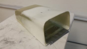
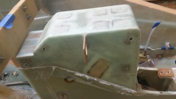
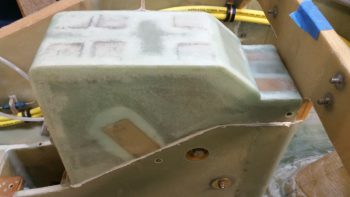
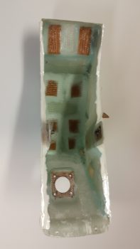
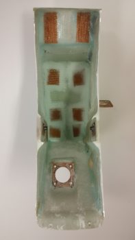
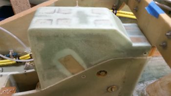
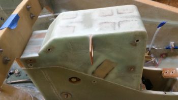
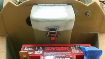
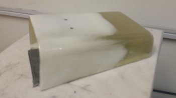
Today was a long build day overall, but not an overly productive one.  The reason being that today was essentially epoxy wipe day for the tool box . . .

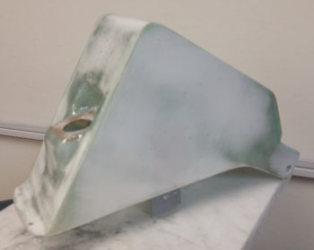
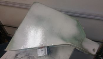
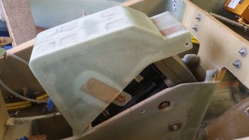
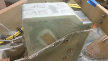
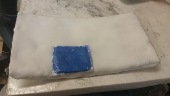
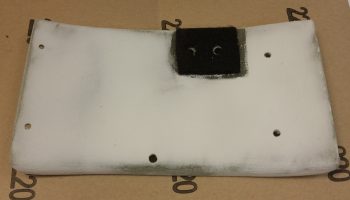
And the aft NG30 cover.

After prepping the parts late this morning, I applied the first epoxy wipe (using West) and then waited 2 – 2.5 hours and then added the next coat, waited and then repeated.  I applied a total of 4 coats of epoxy before letting them alone to cure overnight.

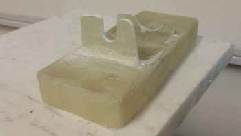
In other news, I cleaned up and shaped the right battery tray flange in preparation for adding a tab (smaller flange) just inboard of the right flange to allow me to mount the taxi light mini-actuator to the battery tray via these right side flanges.

With the aft NG30 cover and tool box body epoxy wipes curing, I checked them one last time and then called it a night.


Chapter 13/22/25 – Finishing nose components

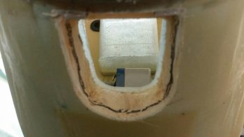
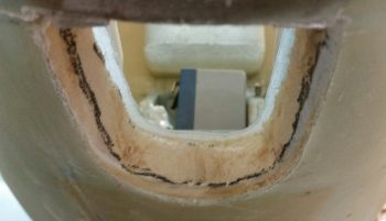
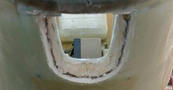
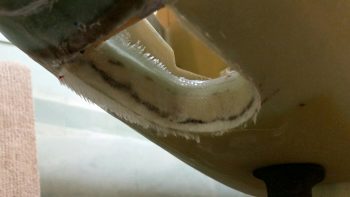
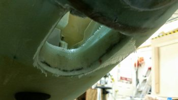
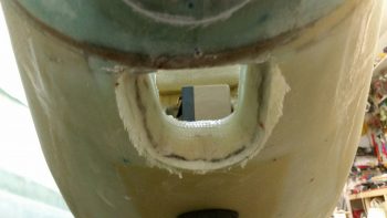
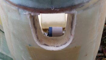
First thing this morning I razor trimmed the cured 2-ply BID layup that covers 3 sides of the bare foam in the taxi light port in underside of the nose.  After trimming the glass edges, I then quickly sanded the corners with some 32 grit sandpaper.
Here’s a shot from below.  And yes, with the MGS epoxy it makes it hard to tell there’s ANY fiberglass on the foam surface, let alone 2 plies.
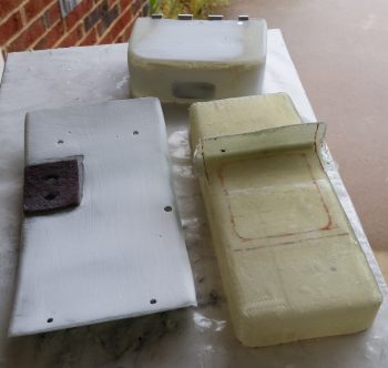
I then assembled some of the nose pieces that I would be working on (clockwise from the top): tool box lid, battery tray, and forward NG30 cover.  This pic was taken after I sanded the tool box lid and forward NG30 cover with 32 grit sandpaper.  In addition, I had done an initial rough trim on the battery box flange, and right after this pic was taken I trimmed the sides of the battery box flange….
… as you can see here.  Again, this flange will slip into the inside of the battery compartment NG30 extension and along with the upcoming right-side flange, will keep the battery secure from sliding left or right.
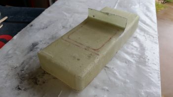
I then trimmed the depth of the flange down to 1/2″.
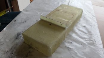
Since I got a bit overzealous with the flox when I installed the battery strap securing cross tube, I needed to make a decent sized half-moon shaped notch in the flange to clear the flox around the batter strap cross tube.
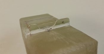
After looking at the setup further and playing around with different configurations, I realized that I could use the battery tray as my securing point for the taxi light mini-actuator.  The actuator fits under the battery tray with no issues and with enough room to move slightly up and down.  Since the battery, and thus the tray, is offset to the left a bit in the battery compartment —to provide maneuvering space on the right side for the big battery cables in the battery compartment— I could then mount the taxi light mini-actuator to the right in the channel below the battery box and still have plenty of clearance for the battery securing strap.

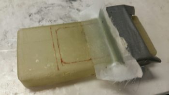
To implement my plan, I wanted something a bit stronger than just a bunch of plies of BID, so I cut out a piece of 1/16″ G10 Garolite to use as the base of my right-side battery tray flange + taxi light mini-actuator mount.  I trimmed the G10 to fit and then set it in place under where the battery tray will sit.  I added just a hair more space on the outboard side of the G10 to allow me to layup 1 ply of BID on that side, unlike the bare outboard side of the left battery tray flange.
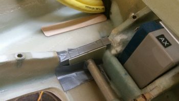
I then whipped up a small amount of 5-min glue and glued the G10 flange to the right underside of the battery tray.
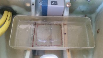
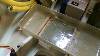
This is a bit later, after I glassed the inboard side of the G10 to the battery tray using 3 plies of BID.  The layup was still just a bit flexible, so I put the battery tray back into the nose and pressed the curing right flange up against the inboard side of the channel to ensure the flange cured as closely and tightly to the channel wall as possible.
I then spent about half an hour mocking up the location and configuration of the nose tool box Dzus latch.  I started with the bottom latch assembly, got it situated and then drilled the rivet holes.  With the bottom latch assembly set in place, I then determined the “exact” location of the top latch assembly, got it set up and drilled the holes for it as well.

With the latch parts ready to be riveted into place, I then pulled them off and started prepping the tool box parts for eventual paint.  I want to get the surface painted before I mount the Dzus latch onto the tool box.  Now, if I can just finalize a color choice!
With my battery tray flange curing, here’s all the parts I would be working with: the front & aft NG30 covers, and the tool box lid & body.  The front NG30 cover and tool box lid will get 3 epoxy wipes, with 2 hours in between the coats.  The aft NG30 cover and the tool box body will both get slathered up with micro for finishing.

This is epoxy wipe #2 (I think . . .) on the forward NG30 cover and the tool box lid.
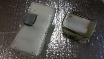
And here is the aft NG30 cover and the tool box both slathered up with micro.  I did the tool box first, and you can see that the micro I applied to it was a bit wetter than it should have been, although it still sanded out fine (as you can see below).
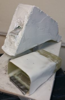
Below represents a good hour’s worth of solid sanding between the NG30 cover and the tool box body.
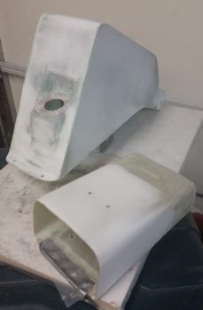
Tomorrow I plan on laying up 1 ply of BID on the outboard side of the right battery tray flange and then epoxy wiping both the aft NG30 cover and tool box body (above).  Either later tomorrow or the day after I’ll start prepping the surface of all these components for high build primer and then paint.
 

Chapter 13/22 – Glassing taxi light opening

Happy Easter everyone!

Today before I headed out for some Easter festivities I did a couple of quick layups.  The first layup was 2 plies of BID on the exposed foam of the taxi light opening in the nose.

I started by sanding & shaping the opening glass & foam. I then created the wedge-shaped channels along the edges of the respective internal and external glass openings since I wouldn’t be overlapping the glass onto either the internal or external glass surfaces.

In the pic below you can see the top wedge channel cut.

And here is both channels cut.

I then whipped up some micro and applied it the foam.  For the wedge-shaped channels I  added a bit of flox to the micro for flocro corner junctions with the glass.

I then pre-pregged the 2 plies of BID and then laid it up in the taxi light opening.

Here’s another couple of shots from left & right angles of the laid up 2-plies of BID.

Here’s a final shot of the laid up 2-plies of BID in the taxi light opening.

Lastly, I wanted a way to make my battery tray removable, but still have it meet the purpose for which I glassed it: to keep the battery from sliding left or right under its tie-down strap.  After pondering it a bit, I decided to glass in a flange that hangs down on each side, just inside the NG30 plate.  That way when the battery tries to slide one way or the other, locked in the tray, the battery tray itself is kept from sliding by these flanges pinning the tray in place.

I decided to glass in just one of these hang down flanges to better allow me to figure out where the second one goes… you know, control my variables and all that.  I used 2 “good” pieces of glass and a bunch of scraps to make up about 5 plies of BID.  Since the battery is a bit heavy, and these flanges won’t be that deep, I decided that 5 plies will give me good strength and still stay very light due to the actual flange sizes.

So, although not much, I did get a couple of significant tasks knocked out today.  Again, I’ll continue to work on instrument-panel-forward components in prep for closing in & glassing the nose top.


Chapter 13/25 – NG30 cover cleanup

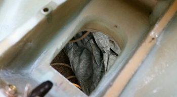
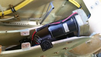
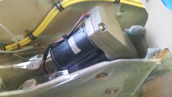
Today I cracked the case open on the NG30 channel, something that I haven’t done since I mounted the NG30 cover well over a year ago.  I unscrewed the 6 screws on the NG30 cover and worked it a bit back and forth before it came right off.

I spent a good 15 minutes getting down into the bowels of the NG30 channel to clean it out.  Many additions and a couple pieces of hardware after a couple of years definitely called for a good cleaning.  To vacuum out the aft parts of the NG30 channel I used a 3/8″ 4130 steel tube as an impromptu shop vac extension to get access.

A long overdue task regarding the NG30 that I needed to complete was the filling in of the slight gap between the bottom edge of the NG30 cover sides and the actual top edge of the NG30s.  The gap on the left side was slightly more pronounced than the right, but I wanted to get ALL the gaps filled in.

I placed clear packing tape on the top edge of each NG30 side that mated to the bottom edge of the NG30 cover in prep for micro to fill in the gap.

I then whipped up some micro –using West Epoxy– and put a thick bead of it all around the bottom side edges of the NG30 cover . . . technically the aft NG30 cover since there are 2 NG30 covers: aft and forward.

As the micro “greened” and got rubbery, I cut the majority of the packing tape away with a razor knife and cleaned up the sides a bit.

After a number of hours, after the micro was about 90% cured, I pulled off the aft NG30 cover.  You can see the pic to the left below the way it looked immediately after I removed it.  I then spent about 10 minutes trimming away the excess micro.  I got the micro at a really good point since it was cured, but still just a bit flexible enough that it cut fairly easily with a razor knife.

After cleaning up the micro edges on the aft NG30 cover, I put the cover back in place to check the interface between the cover and the NG30 sides.  I’m very pleased with how it turned out.  Now with the gaps filled, I can give the NG30 cover a quick sanding and finish it to paint.
The remaining micro that I didn’t use for filling the gaps on the aft NG30 cover, I used to cover the forward NG30 cover for finishing.  I taped up the felt mounting pad for the Matco parking brake, then slathered on the micro.

Quite a number of hours later I spent a good 20 minutes sanding down the micro on the forward NG30 cover.  The micro was still in its sweet spot “green” stage allowing me to cheese grate it, meaning it sanded way easier than if fully cured and comes off in clumps versus micro dust.

Also, here’s a shot of the tool box lid that I micro’d up with some leftover MGS epoxy that I had earlier in the day.  I also cheese grated the lid as well, although I didn’t get an after shot of it . . . yet.

I’ll continue to work instrument panel forward electrical, mechanical and fiberglass component installations until I’m ready to start a concurrent build on both the wheel pants and the top nose construction.


Chapter 22 – AEM box wiring harness

Before I get to the AEM box wiring, I’m going to cover a couple of other items first.

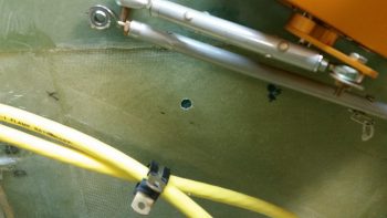
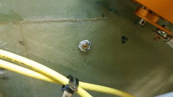
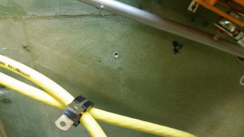
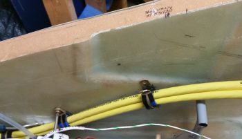
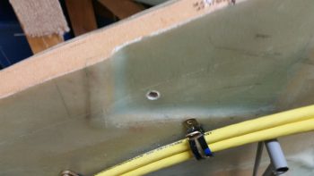
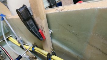
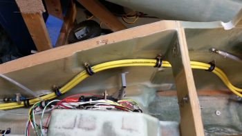
Today I identified another location to mount an Adel clamp hardpoint for my big battery power cables coming out of the nose.  I marked and then drilled the hole for the hardpoint.
Here’s the same shot, but I added the threaded insert in the pic.

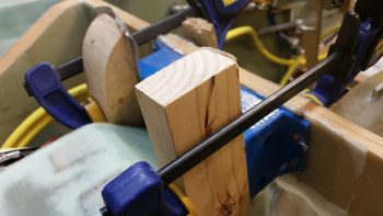
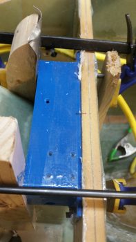
I whipped up some flox and mounted the threaded insert in the hole.  I then clamped a board onto the threaded insert to keep it in place.

I grouped the pics in this post by topic, not chronologically, so I’m jumping ahead about 8 hours here to show the nearly completely cured flox.  I cleaned up the flox that oozed out around the taped up washer.

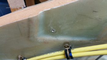
A couple of hours later I removed the bolt and popped off the washer.  I cleaned up the flox, finishing up the install of this hardpoint.
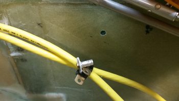
Here’s my progress so far on getting the big battery power cables routed out of the nose battery compartment –with clearance for my right rudder pedal– to my immediate goal: to the instrument panel.

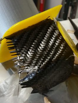
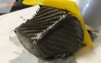
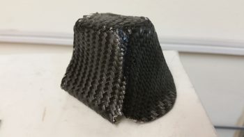
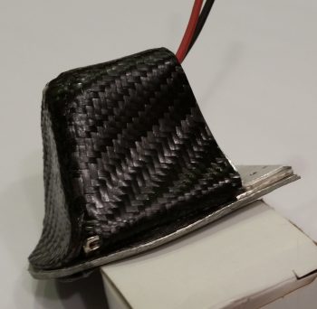
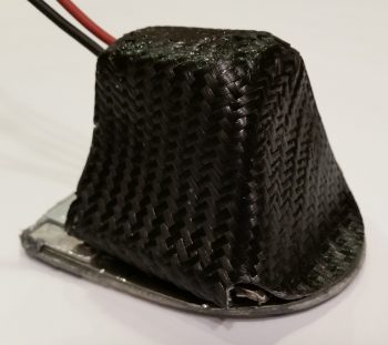
Moving on.  I laid up the final carbon fiber ply on the right side of the taxi light cover.  It took some tricky machinations to get it lined up at the CF intersections, but it all seemed to work out.  To be clear, I did use a “trash” piece of CF here for this final ply.
I checked it a bit later while the epoxy was still just a bit tacky, so I was able to mash down the edges/intersections CF.

After the carbon fiber layup cured, I did a knife trim and quick cleanup.

Here’s a shot of the left side.  I need to still sand it down and hit it with one more application of epoxy.  It’s still not going to win any beauty contests, but it looks a ton better than it did obviously when I first glassed it!

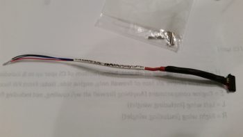
I then started building the wiring harness for the AEM box.  My first task was to configure the wiring connector that came with the laser altimeter.  There are a lot of extra wires that come on this connector harness, so I cut those to a usable length in case I need them later, then wrapped them up and heat shrunk wrapped it to the cable harness.  I then terminated the 3 wires I’m using with mini-Molex sockets and mounted them into the mini-Molex connector.

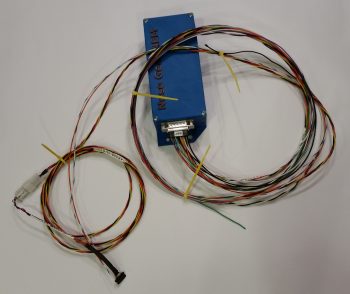
I then spent a couple of hours building the wiring harness for the AEM box.

I measured out the required wiring lengths for most of the wires, and estimated the lengths on a few of the wire runs to the panel.  I performed a continuity check on each wire as I terminated the D-Sub socket on it.

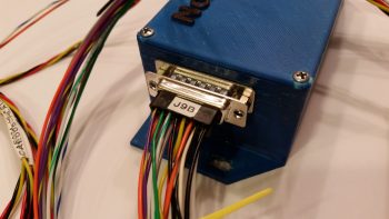
Here’s a closeup shot of the AEM box D-Sub 15-pin connector with all the terminated wires installed.

Tomorrow I’ll install the last big battery power cable Adel clamp hardpoint for my immediate goal of getting these cables’ routing locked down from the nose to the panel. I’ll also start working the pivot arm & bracket for the taxi light to provide an attach point for the taxi light deployment/retraction actuator.


Chapter 22 – AEM Box install

Today I finished installing the Nose Gear AEM box to the forward face of F22.  First, I cleaned up the 5-min glue that oozed out & dried around each Clickbond.  I also sanded down the area around the Clickbonds for a layup of 2 plies of BID around each set.

Apparently Marco had told me that I needed to prep the lid-mounting holes in the AEM box –which of course I promptly forgot– so the there was a bit of separation between the box layers (slight splitting) at each corner from me installing screws into the screw posts. Thus, when I laid up my 2 plies of BID around each set of Clickbonds, I then mounted the box, applied wet epoxy to each corner, and then clamped the box on each side to compress the corners to remove the minor splitting.

Here’s another shot of the AEM box with the clamps applied.

When I laid up the 2 plies of BID over the Clickbonds, I of course peel plied the glass for a smooth transition.  Also, I laid up the BID earlier in the day, so by late night the layups were cured and ready to be cleaned up.  The pic below is from late evening.

In addition, before I laid up the plies of BID over the Clickbonds, I determined the location of my next big power cable Adel clamp hardpoint.  I marked the location with a dot as you can see below, and then I drilled out the hardpoint hole in the sidewall.

I really didn’t get any other in-between pics, so with the same cure rate as the BID for the AEM box’s Clickbonds, by the end of the evening the big power cable Adel clamp hardpoint flox was cured and the threaded insert set in place.

Also, in addition to the AEM box Clickbonds and big power wires’ Adel clamp hardpoint, I also laid up a ply of Carbon Fiber over the left side and aft/bottom side of the taxi light cover.  I did get about half of the top as well, so when I do the last Carbon Fiber ply layup, I’ll work to get a nice overlap on the top and a good seam between the aft/bottom side and the right side.  One point of note is that the pic below is of the taxi light cover layup after I did a rough cleanup.  I need to do a good cleanup of the edges, align sides, etc. before I layup the final ply of Carbon Fiber.

I’ll continue to work these subsequent layups, but also within the next day or so I plan on wiring up the nose gear AEM box.


Chapter 22 – Laser altimeter… etc

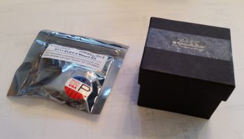
Today I got a nice little surprise in the mail.  I opened up the box to find a very nicely packaged couple of items . . . hmmm?

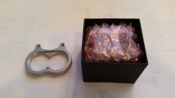
The plastic bag seemed to contain something akin to “aluminum knuckles” while the box had something wrapped in bubble wrap . . .  what could it be?

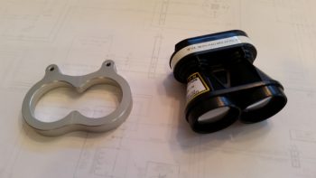
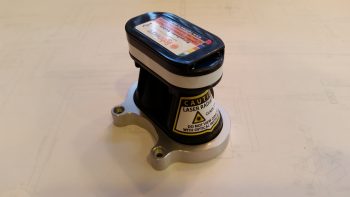
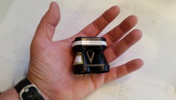
Ahhh, it’s the Laserware SF11/C Laser Altimeter & bracket that I ordered as the final crowning piece to implement Marc Zeitlin’s new nose gear wiring circuit!  As with many actual Long-EZ parts I’ve received over the years, it’s much smaller & lighter than I expected, almost toy like (which of course it most certainly ain’t!).  But then again, it does typically get mounted on a drone.

I did a quick test fit of the laser altimeter inside the unique bracket that is sold by Acroname, the place I purchased the laser altimeter.

Here’s a shot to help show the laser altimeter’s quite diminutive size.

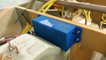
I then proceeded to thread Clickbonds into the mounting holes on the AEM box and I took it down to the shop to test fit it.  I’ve been thinking about a potential mounting issue in that by virtue of being mounted with Clickbonds to the face of F22, it will be difficult to get the box in & out and off those Clickbonds with the way it’s configured sitting down in that NG30 cover notch.  You see, the original AEX box didn’t have mounting tabs so I actually glassed in a couple of hard points into the top face of the NG30 cover notch to mount the AEX box to the NG30 cover, vs. the F22 bulkhead.

My thinking is that I’ll elongate the bottom holes to allow for a front to aft twisting action as the box gets installed (technically not supposed to cut into 3D printed constructed stuff as I’ve learned since it’s not solid plastic, but rather matrixed plastic . . . but this was an oversight on my part in designing the box, although I did push both mounting holes up on the tabs significantly to allow for easier mounting in the NG30 cover notch… just didn’t do enough of what I had intended for getting this thing mounted).  In addition, I’ll shorten the threaded Clickbond studs to the shortest they can possibly be while still gripping a mounting nut.

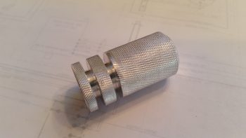
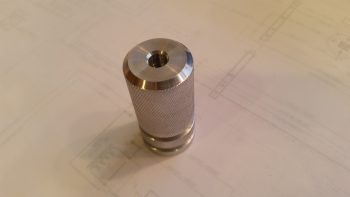
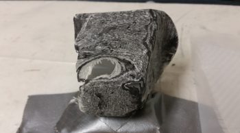
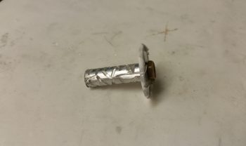
The last item to show today is the lathed knurled insert with flox grooves that I designed as a nose sidewall mounting hardpoint for the pitch trim actuator.  Of course –as fantastic as this looks– I obviously did NOT make it using my primitive neanderthal methods.  Marco graciously knocked this out on his lathe in no time flat and threw it in with the AEM box that he shipped to me literally right after machining this piece.

Here’s another shot of the Marco-machined flox-ready nose sidewall mounting hardpoint for the pitch trim actuator.

That’s pretty much it for today, making today a light build day since I’m off to see a car show with friends.

Chapter 22 – Taxi light cover salvaging

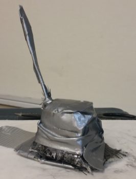
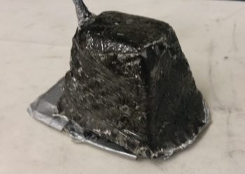
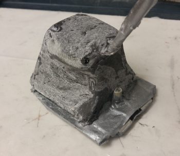
Today was the Big Reveal day for the taxi light cover.  Since my layup was practicing the truest form of accelerated entropy last night, I simply covered it with Saran wrap and taped it up profusely!  This morning I took off the long cross pieces of tape that I used to keep the whole layup from squeezing up the sides of the taped form, really making the cover unusable if it had.  I was now at the precipice of finding out what I had underneath of all this tape.  Would it be usable?  Would have I have to start all over again from square zero?Let’s find out . . .

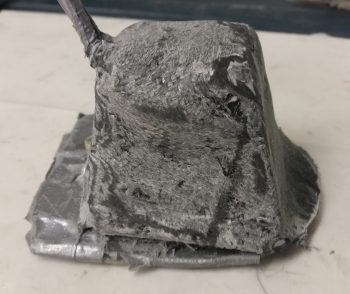
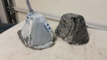
Ok, so here’s the result in Airdog’s crazy layup experiment emporium.  Quite an interesting specimen I’d say, but it really does look usable.  As I’ve mentioned many times before, so much of these one-off custom jobs are ITERATIVE processes!

I grabbed my sanding block and my Perm-A-Grit tools and went to town on the taxi light cover.  I knew that I would most likely create some holes in this cover to get the shape worked out correctly . . . and I was right.  It is interesting that the resulting pics all look quite a bit like snake skin.

Here’s the opposite side.  It may be a bit difficult to see, but because I taped the top of the cover down, it resulted in 2 actions:  One negative, and one ok.  The negative action was that it created “shoulders” on each side of the cover just below the top.  My plan was to cut these off and layup a ply of BID that will bridge across the resulting hole.  The squashing of the top resulted in the 2nd action, which was that it pushed the sides just below the “shoulders” inboard more…. which was fine and actually allowed for a tighter fitting cover (i.e. takes up less room).

Here’s the sanded taxi light cover next to the taped up taxi light that I used as the cover form.

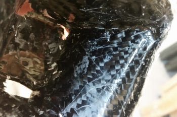
Also, here’s a shot of the inside of the taxi light cover.  Aside from scratches from the scribe I used to pry the cover off, the carbon fiber really looks nice.  Overall, this pic again has a snakeskin look to it (Marco also pointed this out when he saw it).

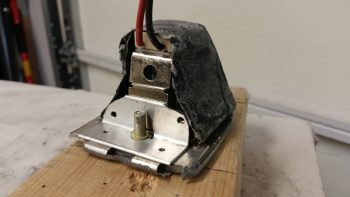
After assessing the cover’s usability –including cover mounting & removal– I decided that because the lips on each side clamp around the flanged base of the taxi light bulb mounting assembly, that I it was not practical to keep the forward side of the cover in place.  I cut off the forward face of the cover to simply allow the cover to be slid on from the bottom (if it’s deployed/out) or aft (retracted) side of the taxi light.  After testing this configuration I could tell immediately that I had made the right call on removing the forward cover side.  Much easier!

I then prepped it for more glass (repair layup, if you will . . .) by sanding it to shape.  This prep also included using the Fein Saw to remove the right “shoulder” just below the cover top, which left a decent-sized hole in the cover.

To keep this story line flowing, I’m jumping ahead here with my pics.  The pic below is exactly what I did above, but on the cover’s left side.  The yellow epoxy spreader is being employed as a form weight to keep the overhanging glass flat against the side lip.  Besides wrapping around the taxi light bulb mounting base to keep the cover securely in place, this side lip will get drilled in 2 places, and be held in place with two 4-40 screws.

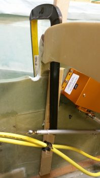
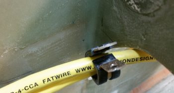
In addition to the taxi light cover, I continued to work on securing the 2 big power cables (one + power and the other – ground) that start in the nose battery compartment and end at the firewall & starter, respectively.  Again, I had to reroute these cables up and over my rudder pedal (you can see in the pic how they get in the way if not wrangled) in an arch/ Bell curve fashion.  With the 1st added Adel clamp in place, I marked the position for the 2nd additional Adel clamp.  Note in the upper right hand corner of the pic my markings for the Atkinson pitch trim actuator mounting.  You can see that I need to get these power cables as high up on the nose sidewall as possible, but still remain clear of the pitch trim actuator mounting.

After marking the spot, I then drilled the hole in the nose sidewall.  This area was a bit tougher to drill since, if you recall, that indented area that this hole was placed has additional plies of BID to beef it up for the mounting of the pitch trim actuator.

I then performed the “poor man’s” knurling of the 10-32 threaded aluminum insert that will be used to mount the Adel clamp in this location.  I wanted to use this threaded insert since it’s a bit more robust than a RivNut.

I then whipped up some flox and mounted the threaded insert assembly (including a taped washer mounted to it with an AN3 bolt).  I then clamped it in place to ensure it would be level with the surrounding sidewall surface when it cured.

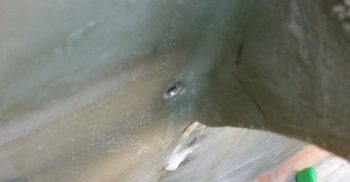
Here’s a shot about 10 hours later after it cured to about 80-90%.  The flox was still just barely soft enough to be easily removed with a razor blade (there was an entire ring of it around the perimeter of the taped washer).

Although it’s a bit slow going, I am getting through all the electrical related taskers on my list.  I expect about another week, maybe 2 at the most, before I’m ready to get back to the big chapter build items again.


Chapter 22 & 25 – Done, Done & Done!

Today I got a few things checked off the list.

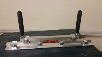
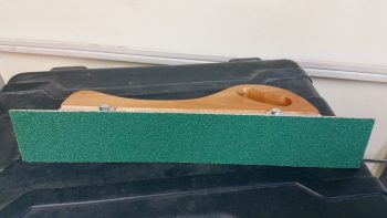
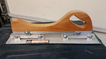
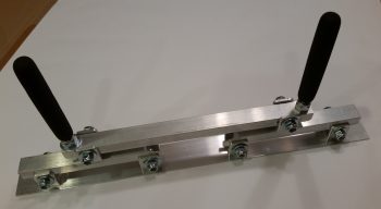
First, I finished constructing a micro spreader to hopefully accelerate the finishing of the aircraft surface in prep for painting when the time comes.

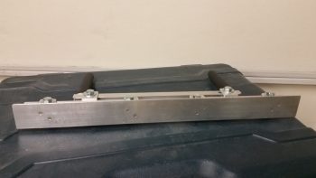
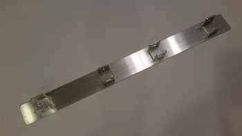
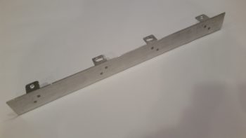
Here’s a shot of the actual bottom plate working surface.  You can see I used 2 counter sunk aluminum rivets per bracket to hold the bottom spreader plate to the 4 individual brackets.  I figured 2 rivets per bracket would be enough since the primary force on the spreader plate is from the top as it pushes the micro over the aircraft skin.  If there is any issue I can of course beef up the bracket attach points.

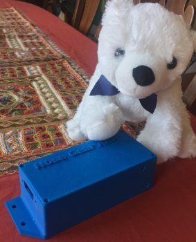
Next, I got this pic from Marco showing my finished Nose Gear AEM box and a United Airlines bear he picked up for my little 7 year old buddy (a friend’s daughter) who loves flying.

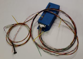
Finally, the box Marco 3D printed for me for the Nose Gear RCU had a slight blemish on the lid, so I’ll hope he’ll forgive me for me filling it in a bit and painting the lid black.  Here’s the finished Nose Gear RCU box ready for mounting into the aircraft.  I will of course have to terminate the wires on the “B” side of the connector.

With my bridge sander, micro spreader and RCU box distraction projects out of the way, I can now get back to my list of electrical system related taskers that need to get knocked out.


Chapter 25 – Finishing Tools

Today I drilled the U-channel on the Harbor Freight handle base to allow me to mount it to the bridge sander.  Before I bolted it all together though, I trimmed the inboard edges of the two cross supports at a sharp angle, and trimmed down the height of the U-channel brackets that hold the handle in place so that there would be no interference by the handle of the sander’s operation.

After all that was done, I bolted it all together and tested it out.  Looks like it will work great!

As you may be able to tell in the pics, I mounted some 32 grit peel-n-stick sandpaper to the bottom plate, and it fit just about as perfect as it can get.

Thus, the bridge sander construction is complete and this baby is operational!

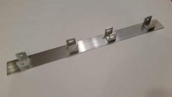
I then got to work on constructing the micro spreader.  I cleaned up all the brackets by filing down the edges.  I then measured, drilled and mounted the brackets to the micro spreader base with 2 aluminum rivets at each bracket.

In this shot below you should get a decent shot of the rivets that are holding the brackets to the base.

Here’s the underside of the spreader base, with the 2 rivets per bracket visible.

It’s a bit late and I didn’t want to make any more loud noises building this thing, so I called it a night and mocked up the micro spreader to see what it will look like when I finish it tomorrow.

That’s all for now folks . . .