Chapter 22 – Nose Gear AEM Box

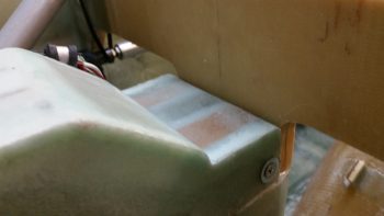
Here’s the latest status on the Nose Gear Auto Extension Module (AEM) that will replace Jack Wilhelmson’s original AEX feature.  First off, I sent this pic to Marco to help show him why I had a requirement that the AEM box be 1.8″ or less: since the AEM box will be mounted in the old AEX box spot, where I have a notch in the top aft side of my NG30 cover that is just a hair wider/deeper than 1.8″.

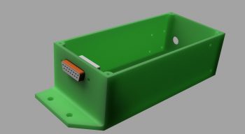
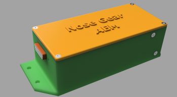
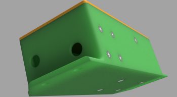
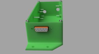
After a number of discussions back & forth with Marco on the particular specs of the AEM box he was able to generate these fantastic renderings of the box.

Here’s the initial rendering.

Then one with the lid and raised letter labeling.

One of the aft, left and top side.

Finally, one showing the internal standoffs for the two airspeed switches and mounting screws.  As you can see, he has included the 15-pin D-Sub connector in the renderings as well.

In the next few days Marco will 3D print this AEM box when he gets a chance.  I just really have to say that everything for the new nose gear wiring & AEX system is going exceedingly well!


Chapter 25 – Self-rolled Bridge Sander

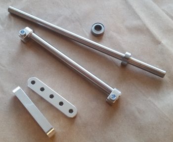
I took a bit of break from my normal build actions to do a quick tool building project. Starting yesterday & finishing today I’ve been working on constructing a bridge sander as Nick Ugolini spells out how to do on his blog.  Once again, I was notified of this brilliant contraption by the watchdog of the canard world, my friend Dave Berenholtz who is blazing through his Long-EZ build down in OZ (check out his blog here).  Coincidentally, Mike Beasley also built one of these as he was finishing up the major sanding of his Long-EZ as well.

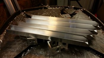
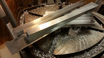
For the base, Nick calls for using 1/16″ thick x 1-1/2″ wide aluminum that you can easily buy from Lowe’s, Home Depot, etc.  I did pick up some of that aluminum for the micro spreader, but for the sander it just wasn’t wide enough for me so I picked up a cheap automotive rigid sander at Harbor Freight after assessing that the aluminum base looked as if it would be amenable to getting pressed into service as a flexible sanding board.  As for parts, one other point of note: Nick calls out for 1″ square tubing to be turned into 6 U-channel pieces and then a separate piece of 7/8″ U-channel to be used inside the 1″ share tubing/U-channel above.  Well, I found the 1″ square tubing, but not the 7/8″ U-channel so I ended up using some 1″ wide U-channel I had on hand with 1/8″ walls, then buying 3/4″ U-channel to go inside that.  Just a slight variation that worked out really well.

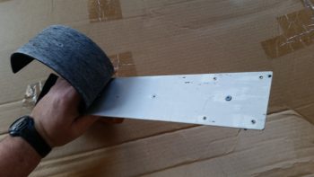
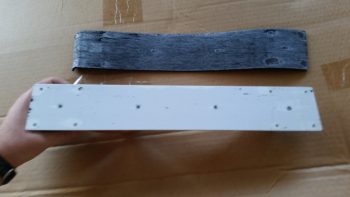
I started off by ensuring that I could dismantle the Harbor Freight sander to ensure I wouldn’t destroy it in the process.  I peeled the rubber pad off the bottom of the base to gain access to its 4 handle mounting screws.

I simply used my fingers to pry off the bottom rubber pad, with an occasionally use of my utility knife to round up any errant pieces of rubber that decided to stay on the aluminum rather than come with the rubber pad.

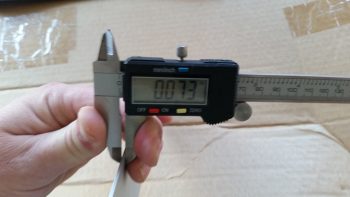
With the sander broken down into an acceptable number of pieces, I then did a final assessment on whether the aluminum base would be flexible enough to be used in this type of sander.

Since the base off the HF sander is only 0.01″ thicker than the 0.063″ (1/16″) called out for by Nick, it looked as if my eevil plan was going to work!

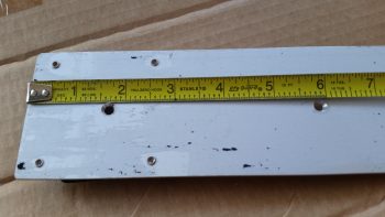
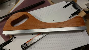
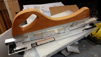
An added bonus in using the HF sander was that the screw holes in the base for holding on the wood handle are at the perfect dimensions that Nick calls for on his blog: approx. 1-1/2″ and 6″, respectively, from each end.  Pretty cool.

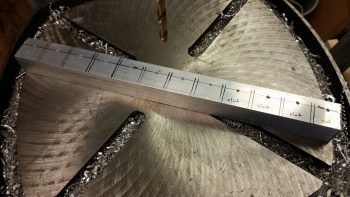
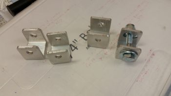
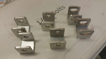
I cut enough of the brackets and aluminum pieces for two of these things since I’ll also be building the micro spreader, but I wanted to get the sander under my belt first.  I marked up the U-channel for 12 each 0.9″ wide brackets, 6 for the sander and 6 for the micro spreader.  Of the 6 brackets for each, 4 will get normal holes drilled through them while 2 will require slots.  Since I’m using cheaper Zinc bolts, 1/4″ is the smallest diameter I could get (versus the 3/16″ AN3 hardware Nick used).

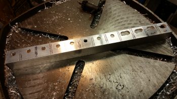
For easier drilling of the holes and the slots, I drilled them all before I cut the U-channel into the respective brackets.  Yes, since I don’t have a mill my slots are pretty sloppy, but for this purpose I’m sure they’ll work fine.

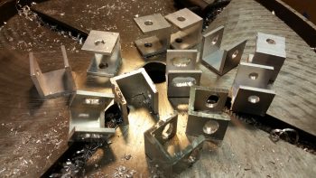
I then cut 12 brackets from the U-channel

And then cut the 3/4″ U-channel into the approximate lengths for the first layer of cross supports.

Finally, I cut the 1/16″ x 1-1/2″ aluminum for the micro spreader to 16-1/2″ long.  I also cut 2 longer lengths of the 3/4″ U-channel stock for the top cross supports/handle bases.

I drilled the 4 holes through the U-channel for my bridge sander and mounted the handle base.

And then started the arduous process of cleaning up each bracket.

I cleaned up 4 straight-holed brackets and 2 slot brackets for the bridge sander, and left the 6 brackets for the micro spreader for later.

I then mocked it all up to see how it would look.  Not bad!

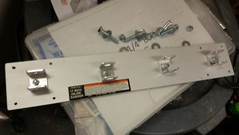
I then drilled a hole in each of the bottom brackets that attach to the base for mounting.  I drilled them just a bit off-center to allow for mounting one countersunk rivet through the base into each bracket to keep the alignment straight.  This was the last action of the evening since I wanted to ponder on the handle a bit.

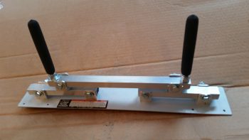
I called it a night, but I couldn’t help but get the feeling that I needed to go with the “traditional” 2-handled setup vs. using the HF sander’s wooden handle.   So this morning I used the handle base/cross support 3/4″ U-channel stock that I had cut for the micro spreader and drilled the final holes into it to allow it to be bolted to the two sander cross supports, and also add two 3/8″ bolts for handles.  I cut about an inch off the top of each handle bolt to allow me to use rubber slip-on grips from McMaster-Carr.

It looked good, but my quick testing of it proved to me that it’s the downward force against the surface being sanded that determines the conformal action of the sanding base, not the actual configuration of the handles.  So my initial hunch was right, and thus I’ll drill up the the base with the wooden handle to see how that works.

I have out-of-town company so the build will be a bit slow over the next few days, but I am happy that I got this reportedly invaluable finishing tool constructed.


Chapter 22 – More Brackets & RCU

I started off today by razor trimming the bracket for the Throttle handle electrical cable P4 AMP CPC connector.

I did the same thing for the right armrest-mounted Dynon intercom bracket that I just glassed in using 2 plies of BID.  On both of these brackets I was able to knife trim them right at their curing sweet spot, so the glass was definitely more on the cured side, but still just a tad pliable . . .  so it cut well.

I then laid up 2 plies of BID on the bottom side of the Throttle handle electrical cable connector bracket.  I used a small flox fillet in the corner and peel plied the glass junction with the sidewall.

I did pretty much exactly the same thing on the Dynon intercom bracket only for a bit more strength I used 3 plies of glass on the bottom side.

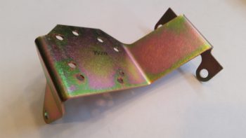
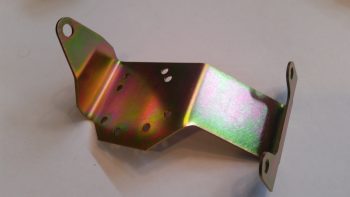
Speaking of brackets, I just received this today so I thought I’d throw it on the blog.  This is the fuel injection spider mounting tab that goes on the top centerline of the engine.  Yet just another item that will go on the shelf for the time being.

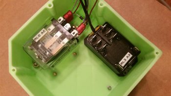
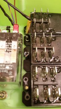
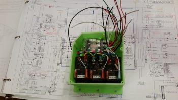
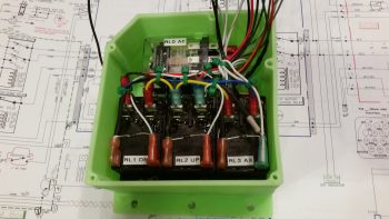
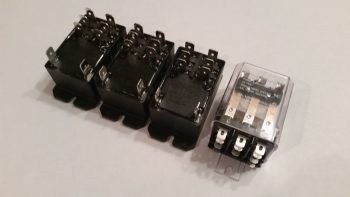
With my bracket glass curing, I started in on mounting the 4 beefy relays into the gear Relay Control Unit (RCU) box . . . fitting name, eh?!  The first relay to go in was the clear cased 3 pole Auto Extension (AE) relay, RL000.  It handles the actual engagement of the gear Auto Extension feature and also is a pass-thru for all the major electrons running the gear up or down.

I ordered this relay specifically with bottom mounting tabs, with the corner of the left tab needed trimmed diagonally just a hair for it to fit properly.   It mounts with a 4-40 screw on each side, each coming in externally from the back.  All the mounting screws coming in from the back side are countersunk to allow the back surface of the box to remain flat, which facilitates ease of mounting the box to the aft side of the Napster bulkhead.

Next relay up to get mounted inside the box was RL003, or the AX relay.  This relay is the one I added back into the mix that charges the small 1.2A backup battery that was provided in Jack Wilhelmson’s original design.  Relay #3 takes control of the system in case of a power emergency to drop the gear down using the 1.2A backup battery for power.  In Marc Zeitlin’s new gear wiring design he doesn’t use this relay since his system incorporates a manual (ratchet) drive for emergency gear extension.

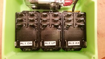
Finally, as for relay #3, I mounted this guy first since it has a unique feature that needed to be dealt with that the other two black relays don’t: down along the top side of the relay is the RXEF-250 wafer style fuse soldered into place that’s used during backup battery charging.  Getting under this fuse to install the K1000-6 nutplate would have been a lot more difficult if I couldn’t get in from the side (where the other two relays sit) to mount the nutplate.  After I mounted this relay, I put some double sided foam sticky tape underneath the wafer style fuse to keep it mounted to the front of the relay for anti-vibration.  I also tipped the box right side up and glopped some E6000 adhesive (yep, the stinky stuff) onto each edge of the fuse to keep it secure to the relay, banned the box outside on the deck for a few hours while it cured and I took off to run some errands.

Upon returning from my errands (which included buying parts for the flexible sander Nick Ugolini describes how to build on his blog) I installed the last two relays: RL001 & RL002 [Note: Simply for space I truncated the relay IDs and labeled them on the actual relays with RL0, RL1 … etc.).  As you can see, these two relays simply control gear up and gear down, respectively.  All went well except for the life of me I couldn’t find a 6th K1000-6 nutplate to use on the top side flange of RL002.  After searching for a good while, and simply not finding the pack of 23 I show having on hand (simply maddening!), in order to get this thing wired up tonight I improvised, adapted and overcame by using an aluminum binder stud, cutting off the top and then quickly Dremeling a not-so-pretty slot for a bladed screwdriver.  I doused it with a good measure of blue Loctite and in it went… Voila!

Here’s another shot of my mounting improvisation . . .

Over the next couple of hours I confirmed & verified the wiring in this box matched exactly what was on the diagram.  Having had to pull all the terminals off their posts, I used a pair of channel lock pliers to compress the terminals just a bit to ensure their clamping pressure was nice and tight.  I then slowly replaced all the terminated wiring back onto the relay posts, performing a continuity check as each set of wires went back in.  After all the wires were back in place, I zip-tied them into place to ensure no wires would be vibrating and wreaking some future electrical havoc by gnawing through a neighboring wire, etc.

Here’s just a closer shot of the internal RCU box wiring . . .

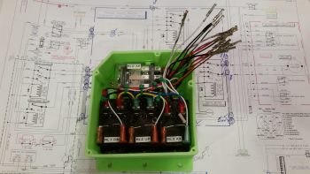
I then cut & terminated all the wires with AMP CPC sockets.  Again, as I finished each wire I performed a continuity check to ensure all was electrical good on that wire circuit from source to connector.

With all the RCU box wiring set to be terminated into the AMP CPC connector, I called it a night.  I may have actually done a bit more but it was quite late and I was collaborating online with Marco (who was in Hawaii for work!) on the specs for the AEM box.


Chapter 22 – Cables, cables, cables

Today’s post is just a quick update showing some cable builds.

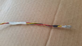
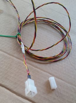
First off is the 3-wire braided cable for the Nose Gear Auto Extend laser altimeter.  These three 22AWG wires will provide power, ground and signal path from the laser altimeter into the Auto Extend Module (AEM).

After terminating the wire ends with mini-Molex pins (above) I then inserted the pins into a connector body.

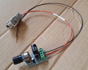
I also soldered 2x 22AWG wires to a 9-pin DSub connector to make up the connector that all the panel components that require an external dimming control will tie into.  The black wire with the DSub pin is a ground wire to the avionics ground bus (G5) for the dimmer module shown at the bottom of the pic below.

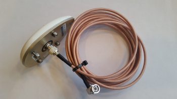
Finally, although I didn’t make this cable, I thought I’d show it just to hint at a bit of progress on the GPS navigator install front.  I ordered a 12′ RG400 cable with a TNC connector on one end (mounted to the GPS antenna in below pic) and a 90° BNC connector on the other end.  Since I only need around 6′ for the GPS antenna, I’ll use about half of the RG400 cable and the BNC connector somewhere else.

That’s all for now folks!


Chapter 22 – Fake it ’til you make it!

With the weather still not up to par for flying on the days I’ve been available, I’ve been working to get more stuff in the coffers for the eventual final push on this build.  I received an order from Mouser with everything but the Laser Altimeter that I’ll need to implement Marc Zeitlin’s new nose gear system AEX mod, combined with Jack Wilhelmson’s original emergency backup battery feature.  After sorting through a myriad of revisions on the melded, morphed version that falls between Marc’s new system with Jack’s old system, I think the new AEX with battery backup and emergency extend is about the best version it can be.

There are some tradeoffs of course with this new system, and some of that will be in weight.  Although I guesstimate it’s not huge, I’m thinking this new system will be a bit heavier with the required laser altimeter and beefy relays in the mix.  To offset some of the added weight effect, I’m mounting these new monster relays in an enclosed box on the left, aft side of the Napster bulkhead.  That should help a tad with moving the CG ever so slightly forward.

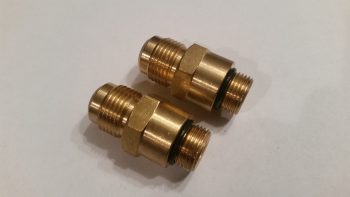
Speaking of weight, I also received two new brass fittings for the oil pump from Buly.  We actually talked a couple of weeks ago and he said he was going to ship them out, but understandably got sidetracked with the sale of his Cozy.  Sad to see him sell it… yet another one of the Ol’ Guard out of the game.

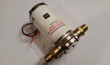
Obviously these fittings are somewhat unique, thus the reason Buly sent them to me rather than just have me order some off of ACS.  Nick Ugolini did recommend that I acquire fittings for 5/8″ tubing, but Buly had these 1/2″ fittings at the ready, and I figured 1/2″ will do just fine.   Maybe these will save a bit on weight with a little less oil coursing through the heating system lines.  Below you can see that I test fitted these new fittings on the oil pump.  Since these brutes are brass, they of course are significantly heavier than if they were aluminum.  But hey, they fit, are in hand and will allow me to have heat in my airplane!

Since I also got a rather sizable ACS order in as well, I decided it was time to take a break from my logistical duties and knock out something that I had started quite a number of months ago.  I had already spent quite a few hours at the beginning of the week logging a bunch of purchases in my tracking spreadsheet . . . and I’m talking stuff from last August, so I wanted to get a bit organized.  My goal before the weather gets warmer, when I can start back on doing some low cost (read: sans high heater settings) layups is to get my recent flurry of research, documentation and instruction manuals put away in my build HQ area (my living room!).  I also spent a good half-hour today doing a cursory cleanup of the shop, but another hour is in order before it will be ready for production again.

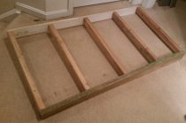
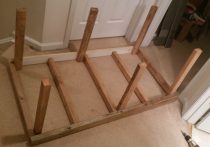
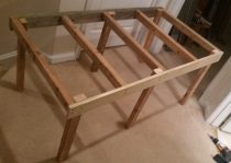
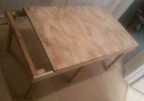
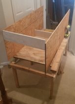
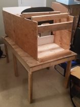
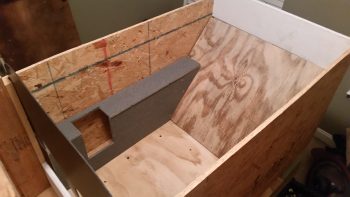
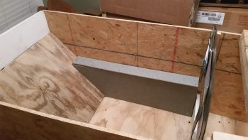
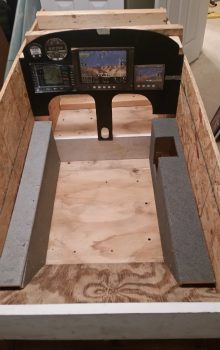
Ok, so my latest mini project was to assemble a bunch of pieces of wood that I cut late last summer to create a cockpit mockup & simulator to allow me test the ergonomics, placement, switchology and operation of my avionics and instruments.  This harks back to my original fuselage mock-up to check for how the plane would feel in its stock dimensions (remember, I widened the cockpit 1.4″).  Now, this version will enable me to mount all my current avionics, plan for new ones, and give me a really close estimate on final wiring requirements for all my panel components.  This latter reason is why I made this cockpit simulator to allow for the installation of the Triparagon.

When the Triparagon is installed I’ll wire up the panel and fire up the components not only to do a good ops check on them, but also to configure them in the panel.  Also, this cockpit mockup will also allow me to finalize any wiring required on the Triparagon.

You may note looking at the pics above that the wood looks a little ratty and non-uniform, and you’d be right!  So far, this entire mockup has been made of completely scrap wood.

Below you can see the right side armrest.  Since I won’t be mounting my second Infinity control stick into the actual airplane, it will get mounted here (although I probably won’t wire it up) into the right side armrest.

On the left side I’ll use the cockpit mockup to figure out exactly where the throttle will get mounted, and how everything else will be configured on the armrest.  You may note the different gray colors of the two armrests, which is me using these as paint color swatches to help me decide the color (or colors!) of my interior cockpit paint.

I’m accomplishing this cockpit simulator mockup construction in 6 phases, and right now I just finished Phase IV.  Phase V will be cutting and installing the avionics in the instrument panel, and Phase VI will be configuring the two separate armrests with the control stick and throttle.

As you can see, once I get this guy up and running, I’ll be able to test out different component and switch locations no matter what’s going on with the actual cockpit.  In addition, this mockup will really come in handy while I’m sanding away on my Long-EZ in prepping it for paint, all the while ensuring that my eletro-whizzies remain dust free!

As you can see, I’m slowly moving towards getting back onto the build.  I do need to really try to knock out this Instrument rating though, although the pace of instruction is very much glacial at the moment!


Chapter 22 – More stuff!

As most of you all know I’m pretty much back in the saddle as far as flying is concerned in my attempt to finish up my Instrument Pilot’s rating.  Unfortunately, I’m definitely not in the saddle where the build is concerned.  In fact, the horse is in the barn and won’t really be ridden for another month or two as far the build.

I have been occasionally taking a break from studying here and there to get a bit of planning and scheming in on some of the miscellaneous electrical stuff that I have yet to finalize.

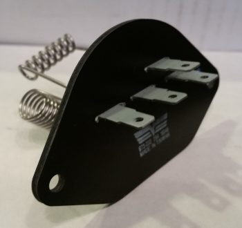
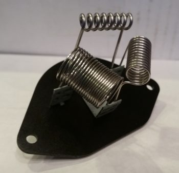
So, I thought I would provide a quick update on some of the pieces-parts that I’ve found to help further my cause.  First off, I finally found a good, cheap basic heater fan resistor coil for my oil heat system.  I got this off of Amazon for about $5.  Not bad, and so far it looks like it will definitely work.

Oil Heater fan resistor coil

Here’s the backside of the oil heater fan resistor coil.  However, since it didn’t come with any specs I had test each of the coil circuits for their resistance values and create a truth table to verify what was what.  It took about 10 minutes, but I verified the entire circuitry of the heater fan resistor coil.

Oil Heater fan resistor coil

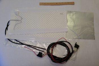
I also ordered a heated seat pad kit for the front seat and/or possibly both front & aft seats (if I can make it work).  The wiring is fairly straightforward and the whole thing will come in under 0.8 lbs. installed.  I think I mentioned it before, but I will be wiring both the heated seat warmers and the oil heat system through a DPDT relay so that only one system can be powered on at any given time.  This is of course to ensure that the charging system, main power bus, and/or battery isn’t overtaxed beyond the capability of my 40A alternator.

Seat(s) warmer kit

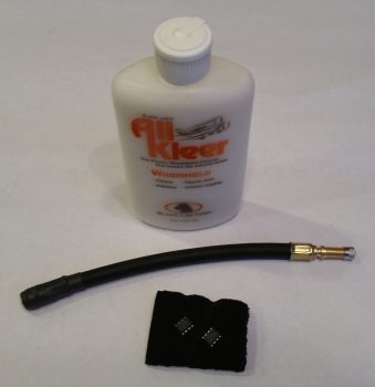
Finally, when I spoke with Rich at Aircraft Extras about adding new AG6 warning screens (shown below) to a couple of new chips for me, I added a bottle of canopy cleaner and a tire air nozzle extension to the order to optimize shipping costs.

Aircraft Extras order

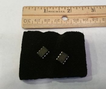
Here are the 2 new AG6 chips that Rich programmed for me.  To be clear, he just didn’t simply program them willy-nilly, but went off a fairly detailed spreadsheet that I created for him that listed out the majority of the field parameters.

AG6 annunciators' updated chips

The 2 new AG6 chips include a verified screen description number to display Canopy “Locked” (versus simply “Closed”) . . .

AG6 Canopy Open Alarm

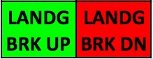
And an updated EZ binary version of Landing Brake Up and Down (versus the already programmed Landing Brake “On” and “Off”) . . .

AG6 Landing Brake Down Alarm

Along with 2 completely new alarm conditions and screen displays:  RAM Air Open and Closed (to ensure I close the RAM air scoop to keep FOD out of the engine) and IBBS Low Volts (IBBS-specific low voltage alarm to show the back-up battery is not charging or is under charged).  I had Rich program these alarm screens as yellow since they fall more in the caution category in my opinion, but I can easily change the colors later on if I want.

AG6 RAM Air Scoop Open Alarm

AG6 IBBS Low Volt Alarm

That’s pretty much all I have to report for now.  I have of course been making notes of any potential system updates or mods as I run across them, but for the most part I’ve either been flying or studying over the past week or so.

Chapter 22 – “Danger Will Robinson!”

As I mentioned before, sideline to getting back into the books and refreshing my tired mind on Instrument flying stuff, I’ve been cleaning up some electrical system stuff that is a natural result of integrating systems and devices together.

One such area of my electrical system is on the warning annunciators.  I decided to crack the code on just how these AG6 annunciators (again, I have 2) are programmed.  Well, the programming manual might as well have been written in Mandarin Chinese when I started, but after working through it bit by bit I finally got the swing of it.  The weirdest thing about these annunciators is that you only have one interface to program them, the button –also the annunciator screen– which makes things interesting.  There are only 2 inputs that the screen recognizes, akin to Morse code: a short press [<0.7 sec] and a long press [>0.7 sec].  It also recognizes the rate and combinations of these presses together (analogous to the ‘double-click’ on a computer).  Again, once I worked at it a few times the input was really a non-issue. Add a little patience and it’s actually something new and fun.

One issue I had was that I failed to realize that there was an online spreadsheet that had the codes that I needed to program (or reprogram) these annunciators.  My being remiss in having this critical document on hand was evident after a few telephone and email discussions that I had with Rich from aircraftextras.com.
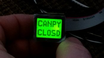
AG6 Warning Annunciator Screen

With the spreadsheet in hand I was able to effectively program about 80-90% of the input screens that I wanted.  To be clear, I had the installation manual that described the entire programming process, but what I didn’t have was the spreadsheet that had the required codes to tell me what screen ID numbers to input for the warning screens that I wanted annunciated… until after talking with Rich of course!
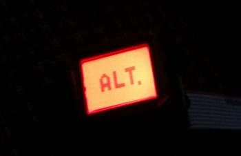
AG6 Warning Annunciator Screen

Since the AG6, as with what seems like the majority of experimental aircraft products these days, is traditionally geared towards the RV crowd, there are some unique warning annunciator screens I would like that are not on the list of hundreds of screens already preprogrammed on the AG6.

After finalizing all the programming I could do, I determined that I needed 2 completely new screens and slight modifications to 2 other screens to provide me what I’m looking for in my warning annunciation scheme.  The 2 new screens are “IBBS Low V.” for my IBBS unit, and “RAM OPEN” / “RAM CLOSD” for my engine RAM air intake.
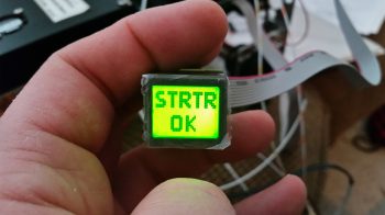
AG6 Warning Annunciator Screen

As for the pics above, I would like to point out that the top pic portrays the actual visual appearance the best of these 3 pics.  A brilliant, bright red light is really hard to capture with any of my cameras, and comes out looking orange and pale, and is not representative of its actual appearance (the same thing holds true for the indicators below).

Finally, the top pic showing “CANPY CLOSD” is one that I want changed to “CANPY LOCKD” (there is a screen ID for the latter, but for some reason it too is showing as simply “CANPY CLOSD”).  There will be no “ALT.” screen, but rather “Low Volts” for the main bus low volt state (via the B&C LRC-14 voltage regulator).

The last pic above is the annunciation that will show up for a few seconds immediately following engine start to show that the starter solenoid is not hung up (“hung start”).  As a reminder, a hung starter state is dangerous since huge current flow is rushing through the system from battery to starter and back unabated, which will fry the battery… with even possibly more bad smoking, fiery stuff to follow (Dick Rutan addresses this in CP #99).  To be clear, the more important screens are the red, flashing warning annunciations that will come and stay on until recognized with a screen press, or the warning state ceases on its own.  Thus, the entire time the starter is powered there will be a flashing red light depicting “STRTR ON” until it’s disengaged, at which point the green annunciator screen shown above will flash on.

Moving on…

As I mentioned the other day, in my quest to finalize both my warning annunciation scheme and my device ON/OFF indicators (below) I ran across a discussion from Paul Dye (Editor in Chief of KITPLANES mag) arguing that a simple, separate, non-EFIS or engine management system linked low oil pressure light should be incorporated into one’s lineup as a primary tell-all of engine health if your spiffy, modern glass cockpit goes Red-X on you.

I thought that for 2.3 oz it sounded like some good informational “need-to-know” insurance, so I bought this oil pressure switch from B&C to incorporate its alarm out state as an input into the AG6.  When the oil pressure is low (as in pre-engine start) a red, flashing “LOW OIL P.” annunciation will alarm (this is an adjunct warning light, not a replacement, of the EFIS-depicted engine instrumentation).
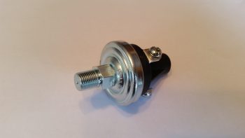
Oil Pressure warning switch

This oil pressure switch actually has 3 electrical connections to allow for a Hobbs meter to be wired up as well, if so inclined.  Here’s the back of the oil pressure switch, showing the N.O., N.C. and COM electrical connection posts.
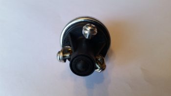
Oil Pressure warning switch

Lastly — something I’m extremely pleased with is these babies below that were delivered today!  Again, as I mentioned before, after I assessed my warning light system I decided that I would revise my original decision to run all but one pair of LED panel indicators through the AG6 annunciators, in order to make the AG6s strictly inflight/actual warning annunciators. Thus, those devices that I simply wanted to know were in an ON or OFF state would get downgraded to just LED lights again.

Now, I did order a myriad of LEDs in one my of Mouser orders, but my spidey sense told me there had to be something better out there.  After messing about online a bit here & there over the past few weeks, I found these.  They’re simple LED indicators for airline cockpit simulators that I found on Ebay (these are 737 panel indicators).  I wasn’t sure if they would work, but at less than $4 a piece, I figured I would pull the trigger and test them out.  I’m very glad I took a chance!
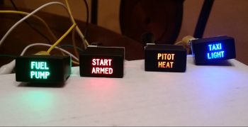
Non-warning ON/OFF LED Indicators

Again, the red and green indicators don’t photograph well, although the blue and amber lights are fairly good depictions of how they look.  These 4 items are the ones which I wanted their ON/OFF states communicated since –other than the fuel pump under my thigh support– I would have no real way of knowing if they are actually in an on or off state (yes, I could tell if the taxi light is on at night, but how about during the day?).
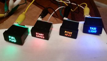
Non-warning ON/OFF LED Indicators

Best of all, these are low current and very lightweight indicators, with all 4 weighing in at less than 0.05 lbs.  I will run them through a dimmer so that their brightness can be dimmed at night, and turned up to their brightest during daylight flying.  One point of note is that I reserved the brightest LEDs (red & blue) for the ground op devices: START ARMED to indicate when the engine starting system is ready, and the TAXI LIGHT on indicator.  This leaves the FUEL PUMP and PITOT HEAT as the less bright, but still clearly visible, indicator lights for flight ops.  In addition, I reserved the only red light, denoting an actual real hazard, for the START ARMED indicator… since a swinging prop typically ensues immediately after it lights up.  So, although definitely listed in the “great-to-know” category, the other indicator lights (and their associated colors) do not denote hazardous states.

Ok folks.  Transmission ended, and back to studying for me!

Chapter 22 – Taxi Light Actuator Test

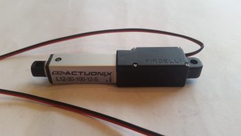
Today I performed a final test for the circuit that drives the Firgelli/Actuonix L12-S mini-Actuator for the swing-down Taxi Light assembly in the nose of the aircraft.

Firgelli/Actuonix L12-S mini-Actuator for Taxi Light

I actually set this up last night and messed around with it a bit.  Unfortunately, I had one power connection off so it wasn’t working in both directions with a simple ON-OFF switch. For a bit I thought I might need a more esoteric relay along the lines of a latching relay until I found my wiring miscue.

This morning I made the correction and Voila! . . . the actuator worked like a champ with the up/down throw of a simple ON-OFF switch!  The ON-OFF switch of course mimics the blue ON-OFF push button located at the bottom front of my Infinity stick grip.
I shot a short video to show how nicely this mini-actuator works, and show a bit of the wiring behind it, including the core part of this circuit: the DPDT relay:

From here on out for the next couple of months I’ll really be focusing on getting my Instrument Rating, so I’ll most likely not be posting nearly as much.  I will be prepping and working on the wheel pants when I get a chance, but as I’ve said before, the build will be my #2 priority for the first couple of months of this year.


Chapter 22 – A bit more electrical

Happy New Year!

Over the holidays I’ve been quietly working on the odd & end aspects of various areas of electrical stuff in my push to get as far as I can on finalizing the electrical system before moving on with the rest of the build.

Yesterday I finalized a 2-day process to figure out the wiring going out to the wing Nav, Strobe & Landing lights.  I had a quick but informative discussion with Dean from AeroLEDs and pulled the trigger on a couple different types of shielded 20 AWG electrical wire and some more connectors from Stein.  I also assessed & designed a reroute of my com radio antenna cables to get them away from the noisy wing tip light wire runs.

With final decisions made on the wing wiring, I finalized updating my wiring diagram for the Landing/Taxi/Nav/Strobe lights.  I also updated the wiring diagram for the AG6 warning annunciators, driven in part by my decision to only have actual warning annunciations communicated by the AG6 displays.  Thus, I decided to transfer the simple ON/OFF LED displays for those items that I merely want to know if they are in an on or off state (start armed, taxi light, pitot tube & fuel pump) off of the AG6s.  I ordered what look to be some high end LED annunciator buttons off of Ebay for these 4 ON/OFF indicators.  I’ll assess those when they arrive and move on from there.

I have one more item to report as for warning annunciators: as I was doing my research for what I should employ as simple device ON/OFF indicators, I ran across a post on the VAF forum from Paul Dye (Editor in Chief for KITPLANES magazine) arguing the merits for having a backup Oil Pressure warning indicator that was not integrated into the glass cockpit system… in other words, not reported by the EFIS or the Engine Management System.  I assessed this for a few days, and finally concluded that if I did have a catastrophic display outage and was looking at nothing but red “X”s on the EFIS displays that it would be nice to have ONE annunciator light to provide the overarching status of my engine health, and oil pressure is arguably (as Paul Dye so eloquently does) the biggest. For a weight penalty of 3 ounces, I decided I would incorporate this backup oil pressure status into my warning annunciation scheme.

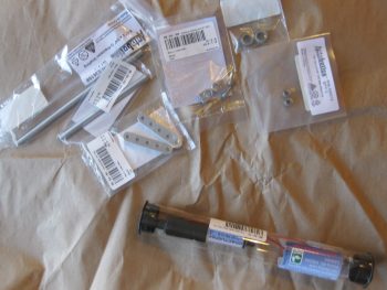
Today I finally received my L12-S mini-actuator for driving the Taxi Light assembly deployment and retraction.  As you can see in the pic below I bought a number of ancillary parts that should facilitate the install.

Actuonix mini-Actuator & parts

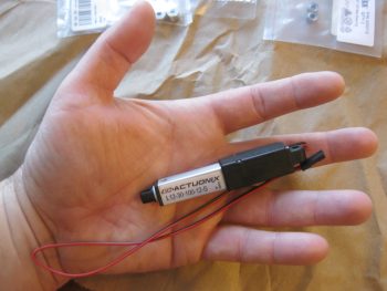
Although I knew it when I ordered it, the tiny size of this actuator is really hard to believe until you actually hold it in your hand, which is exactly what I did!  Again, seeing this pic it’s not hard to believe that this thing only weighs 34 grams.

Actuonix L12-S mini-Actuator

Here’s a shot of the Taxi Light swing down assembly parts that I picked up with the L12-S mini-actuator.

Taxi light actuator hardware bits

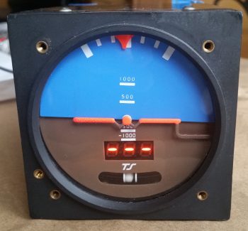
I also decided that I was long overdue in doing a thorough ops check of the Trutrak 3-1/8″ ADI that I picked up off of Ebay from an RV driver as an attitude reference backup to my glass panel.  I did a quick review of the instructions and fired it up.  Since I had the GPS puck plugged in I wasn’t quite sure why I wasn’t getting the GPS track info in the window where the 3 lighted dashes appear.  Well, I got back into the manual, did a quick online search and still couldn’t find an answer.  Hmmm, did I have a bad unit that needs repaired?

I couldn’t ponder on it long since I had to run out and help a friend move some furniture (the bane of being a pick-up truck owner!).  Well, I arrived at the location a bit earlier than they did, so I decided to call Trutrak and find out the story on the 3 dashes.  It turns out that the 3 dashes are normal & that no track info is displayed until the aircraft is in motion…. Ok, another good instrument ops check!

Ops checking Trutrak ADI

Tomorrow I’ll test out my taxi light actuator circuit design & operations by wiring it up to the DPDT relay I have on hand.


Chapter 22 – Electrons vs. Paper

Well, as I pointed out, between the holiday stuff, the football, and more importantly, this nasty cold I’m fighting, I have abided by my previous statement that the build would slow down quite a bit.

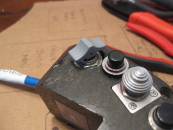
I did finally receive a pack of 1/16″ roll pins that I ordered, so I was able to mount my gray finger grip back onto the landing brake switch post (permanently).  Last year I had to drill out the original roll pin in order to get the finger grip off to then allow me to remove the switch from the throttle handle housing.  In fact, the hole that is now visible on the side (top) of the switch grip wasn’t there when I started last year and was created as a result of my drilling endeavors.  Presently, I put some E6000 on the bottom side of the switch to help seal up the roll pin hole.

Barring any other adventures, this does it for the completion of my throttle handle switch installation, wiring & prep.  Over the next few days, when I start feeling a LOT better, I’ll drill a hole or two in the lower left area of the instrument panel bulkhead to mount some Adel clamps for use to secure the throttle handle cable (and whatever other wiring needs secured).

Air Brake Toggle Switch Finger Grip

The remainder of my work over the past couple of days has been around finalizing the electrical system push. For one, I started compiling a list of even more electrical system components I’ll need for the future (shielded wiring, consumables, etc.).  I also printed out a couple of batches (~12) of heat shrink wire labels and attached some of those.

One main thing I’ve been doing, since I’m really not feeling up-to-snuff, is updating my electrical diagrams.  You can imagine there is simply a myriad of data that needs to be annotated (in digital form, vs. my own chicken scratches!) on these diagrams: wire colors, wire sizes, wire labels –these change a lot with the addition of connectors– circuit changes, etc.  I would say that it’s not uncommon for me to have anywhere from a dozen to 50 data points on each diagram that requires updating, which in and of itself isn’t necessarily or overly difficult.  However, the crosschecking (or consolidating) of ground points, bus tab positions (again, or piggybacking) –and making the decisions on those as well– is what eats up a good bit of time.  And of course there’s the oft required research that may accompany any such decision.

In addition, I’ve done (or simply documented) major circuit design revisions, mainly the items that are controlled via the airspeed switches and/or ancillary relays.  I also did a major overhaul of my panel dimmer and cockpit lighting & dimming circuit design as well. As a point of reference, I haven’t touched this particular wiring diagram since June 2014, so it definitely needed some attention.

I’m about 2/3rds through the diagrams and don’t have that many more to go.  Once I start feeling better, with my electrical system documentation updated, I’ll be ready to start back on some real work . . . like perhaps some wheel pants.  I will note that the wheel pants are most likely the only thing that will get done in the next couple of months since I really need to start flying again: A LOT!