Chapter 22 – Uh, more electrons please!

Well, I’ll be darned if another task didn’t blow up into a huge project.  I had planned on using this morning to finalize the electrical stuff I did yesterday: print out the diagrams and connector pinout sheets and verify a few connections.

I did just that and then, although electrical in nature, got back to working on the GIB area by working on the circuit for the GIB cabin lighting.

My GIB area cabin lighting essentially consists of 2 zones:

  1. The upper zone lit by a red/white LED map light.
  2. The lower zone lit by red/white LEDs mounted in the sump low fuel sensor covers.

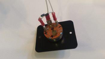
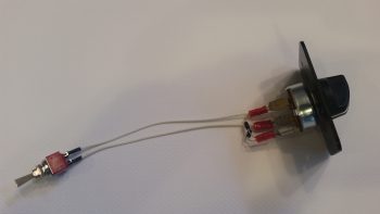
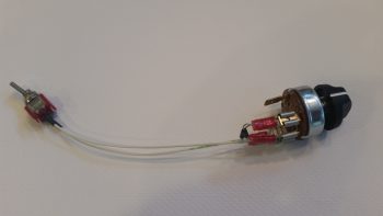
I decided to start on the switch side which consists of a mini-toggle that allows for selecting all GIB area lights to be lit either RED or WHITE.  This then connects to a rotary switch that allows the GIB to determine which lights are on or off with the following positions:

OFF – FLOOR – MAP – BOTH

So I got both switches configured & initially wired up, and all was fine until I had to tie in the LED map light.

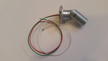
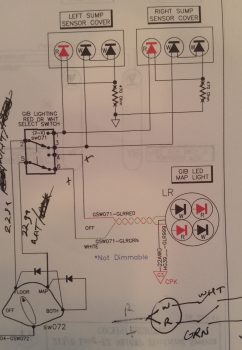
As you can see the map light has 3 wires: white, red, and green.  I mistakenly assumed that the separate, selectable red and white set of LED lights were powered by the red wire for the red lights and the white wire for the white lights, with the green wire (maybe I’ve spent too much time installing house light fixtures!) being the ground wire.

Which is exactly how I had it drawn up for years!

But, alas, the manufacturers of these map lights pulled a switcharoo and pretty much made the install specific to powering the lights through an ON-OFF-ON switch with each light being controlled by closing that color (red or white) circuit to ground with the switch. You can see an initial swag I took at this in the lower right corner in the pic above… albeit I lopped off the ground symbols when I cropped the pic.

I played around with it for a while, getting a bit pissy having to “waste” time on a small luxury item as this GIB map light.  Moreover, all day my Chi was apparently way off center because I was letting a ton of that critical electrical smoke that must be contained out of as sundry items such as relays, diodes, wires . . . you name it! I clearly had the reverse midas touch so when I was done creating smoke by incidental shorting of wires, etc. I decided to dare not touch the plane nor attempt any glassing later in the evening!

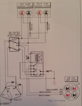
Although I did –after much effort, angst, creative use of expletives, persistence and hard thinking (which was like pushing a brick wall!)– finally tested out a good circuit for the GIB LED lights, which took a few hours and involved incorporating a spare small DPDT relay I had on hand (don’t ask how long it took me to find it!).  BUILDERS HINT: Install the diode in the circuit the correct way!!  Ask me how I know . . .

The challenge was that I already had the entire circuit designed and mostly constructed, so I was adding on to the tail end of it and couldn’t really pick my power & ground wires from scratch (without adding more long wire runs or even more complexity).  I eventually got it, and thus I present to you the new GIB LED lighting circuit:

Yes, hopefully tomorrow I can actually get back to the REAL GIB area tasks!


Chapter 22 – Electric all the way!

Well, as not that uncommon in this build, what was supposed to take a few hours ended up taking up every minute of my day today and propelled itself into the wee hours of the morning.

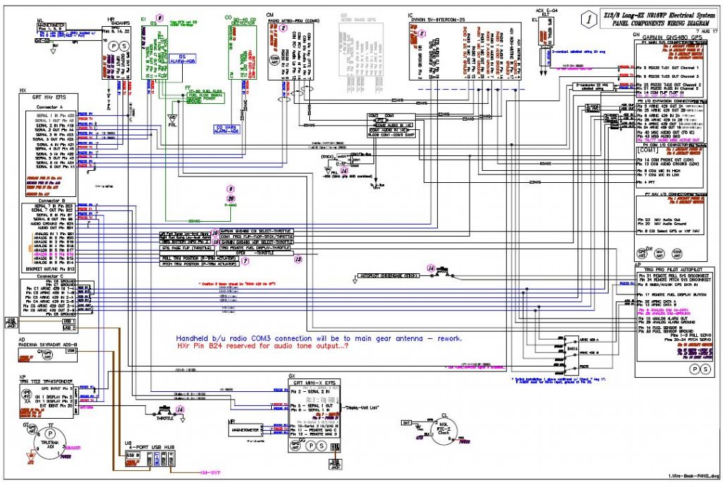
But my immediate task is done . . .  for now of course!  I tried a few different ways to get this on the screen, but alas my JPG captures on my CAD program suck.  So I just took a screen shot (pic below).  It gives you a general idea of what I was up to all day yesterday sorting through essentially a massive pile of spilled spaghetti.

I pretty much assessed every wire and every connection coming out of the GRT HXr EFIS (PFD), GRT Mini-X EFIS (MFD), Garmin GNS480 GPS receiver, and Trio Pro Pilot Autopilot. I identified if the wires would simply be run from point A to point B, or in a twisted pair or shielded conduit, all based on the requirements coming out of the installation manuals or the manufacturer’s guidance.  Where there was no specific guidance I turned to words of wisdom from the grand pupa of aircraft electrons, Bob Nuckolls, by referencing his masterpiece, The AeroElectric Connection.

In addition I clarified some info via phone calls and emails as I did with Chuck from Trio Avionics.  And will do the same with GRT tomorrow.

As I mentioned yesterday, I also labeled every RS232 serial pair and ARINC 429 pair for the data signal wires with their respective configuration labels and correlating baud rates that will be used when setting up the individual components to talk nicely amongst themselves.  I was also able to reallocate and free up some serial ports based on my newfound knowledge and tweaking of my system (also facilitated by some updated manuals such as a new 2017 install manual for the Mini-X).  This, in turn, both reduced the physical number of wires and allowed me to clear off unneeded ports that I was tracking on the diagram above.

With the wire types identified for each port, I was then able to massively rework my Panel Quick Disconnect (PQD) connectors and consolidate all the HXr EFIS harness wires on the J4 PQD 37-pin D-Sub connector.  I was just short a couple of positions, so I moved the power off the J4 connector and repurposed the J10 connector label for a new 4-pin mini-Molex power connector (HXr primary, secondary and tertiary power plus ground).  The old J10 connector got bumped down the line and is now J12.

Below is a page out of my connector pinout tracking sheets packet.  I track literally every wire, pin & socket in every connector on this aircraft.  As you can imagine, I’m waiting for the day when I can stop updating these sheets!

In addition, I did exactly the same thing in consolidating every wire for the Mini-X through the J3 PQD 15-pin D-Sub connector.  This is very significant in that it allows me to simply unplug & remove my HXr EFIS by disconnecting only 2 connectors: a D-Sub & mini-Molex (ok, and a USB cable . . . you got me!).  Moreover, If I choose to, I’ll be able to disconnect & remove my Mini-X EFIS by disconnecting 5 things: a D-Sub, a USB cable, the GPS antenna cable, and of course the Pitot & Static connections.

After I finished reworking my panel component wiring diagram and the pinouts for the 3 PQD connectors, I then did a scrub of every wiring diagram I have on hand, which is nearly 30 diagrams.  In addition to the panel component wiring diagram, I had to do significant updates to 8 other diagrams.

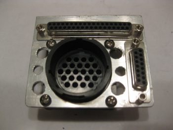
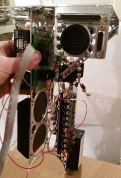
To help bring all this massive paperwork drill to life so you can see it in the physical world, I went back and snagged a couple shots of the Panel Quick Disconnect (PQD) connectors in the PQD bracket (still in its rough state before cleanup) so you can see what I’m talking about.  The 37-pin D-Sub J4 HXr connector runs across the top, while the 15-pin D-Sub J3 Mini-X connector runs down the right side.  The big round 24-pin connector, which admittedly is sparsely populated now (read: scalability) is the P6 AMP CPC connector.

Here’s a shot of the PQD connector bracket at the aft right corner of the Triparagon’s top cross shelf.  The PQD bracket is situated right below the aft face of the Trig 22 Transponder.  In addition, the PQD connectors are only a scant 4.5″ (IRRC) from the aft side of the HXr and Mini-X . . . so close in fact that I could not physically install the cable clamp on the aft panel-side P6 AMP CPC connector and still have clearance to run all the wires!

With my short deviation back into the world of electrons over (…for now!), I can get back to tackling the GIB area and start seriously planning on knocking out the nose and canopy (with perhaps a quick sideline tryst to finish the wheel pants?!)

Chapter 22 – Panel Cross Connects

Well, I’m back from my nearly weeklong trip down to the North Carolina coast and Virginia Beach.  This past Thursday Marco flew down to New Bern, NC and picked me up and flew me back to his EZ’s home base at Chesapeake.  At 45 minutes airport to airport and averaging just over 6 gallons of fuel an hour, you can bet I’m motivated more than ever to finish my Long-EZ!

Spending a few days with Marco and Gina was great of course.  Since Marco is actually interconnecting all his panel upgrade components (GRT EFISs, Garmin GNS480 GPS, etc), it gave me a lot more insight on the configuration settings required to get all these panel components to talk to each other.

With all this configuration settings stuff fresh in my mind, when I returned home on Saturday I spent about 3 hours digging into the manuals to facilitate adding port speeds, port labels and IDs to my wiring diagram interconnect wires for my PFD, MFD, GNS480, Trio AP, transponder, etc.  With a deeper understanding of the ARINC connections, this process also allowed me to further find a couple of design configuration questions that I need to get some answers to.  So I fired off an email to Chuck at Trio to get some of those answers.

I continued my digression (or distraction!?) yesterday as I got close to wrapping up my panel wiring diagram by ID’ing specific wiring types (twisted pair, shielded, standard) for each cross connect.  I also created a spreadsheet that IDs all the major programming configs for my separate panel avionics/instruments.  I’ve already configured the majority of settings –as far as I can currently– on both my Garmin GNS480 GPS receiver and my GRT Mini-X EFIS.

Tomorrow I’ll start off by rewickering my Panel Quick Disconnect (PQD) D-Sub pinouts to allow both GRT EFISs –PFD & MFD– to be quickly disconnected when I remove the panel.  So, a minor rabbit hole, but I think it will be good to get the avionic/instrument components’ configurations tweaked while it’s all still clear in my mind.  I’ll also continue my electronics quest by testing out my GIB lighting circuit and then try to get those into place inside the covers that get installed over the GIB thigh support sump low fuel sensors.  Not only will that be another major GIB area install out of the way and confirm some proposed circuitry, but will be another electrical install task completed.


Chapter 22 – Oil heat ducts

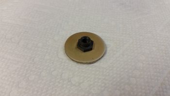
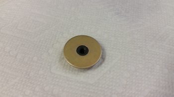
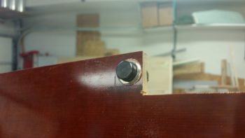
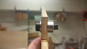
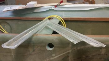
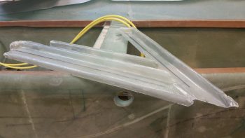
First off, I thought I would show you a couple good shots of the EZ Point Locking Nut that I’m using to attach the heat exchanger to the duct network along the lower horizontal duct.

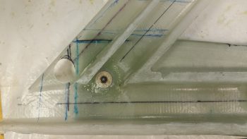
Today I started off by sanding the interior surface of the glass at the entrance to the GIB high air duct in prep for attaching the forward EZ Point nut that will be used in concert with the aft EZ Point nut to secure the heat exchanger to the duct network.  I then floxed in and glassed over the forward EZ Point nut with 1 ply of BID.

I then peel plied the forward EZ Nut Point 1-ply BID layup.

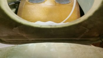
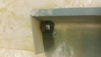
I had to run up north to help some friends that are moving out of the area here in a couple of weeks.  When I returned back home I pulled the peel ply off the forward EZ Point nut layup and cleaned it up.  Here’s a shot of both installed/glassed-in EZ Point nuts along the lower side of the duct network for mounting the heat exchanger.

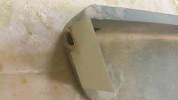
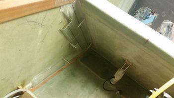
Here’s the same shot from the inside of the duct network.

I then did some final preps for floxing the lower outlet duct onto the heat exchanger to meld these two components together permanently.

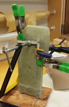
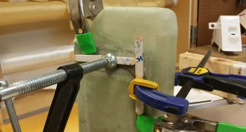
I then whipped up some flox and floxed the lower outlet duct onto the heat exchanger.  I then clamped the lower outlet duct into place on the heat exchanger.

Here’s a closer shot.

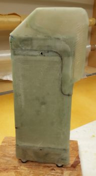
I then headed up north again to help out my friends, and upon my return I removed the clamps and cleaned up the seam of the floxed-on lower outlet duct.

Tomorrow should be a big build day and I plan on continuing my efforts on the oil heat system & ductwork.


Chapter 22 – It’s all about the oil!

Oil heat that is!

Again, the Chapter 22 thing might be throwing you off a bit since it’s electrical, but currently that’s where I have my oil heat system.  Thus, any discussion on the major ventilation system in this bird is married to the heat system, and ends up in Chapter 22. Weird huh?!  Yep, well, nothing about building Long-EZ’s can be considered normal!

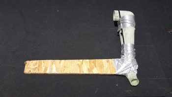
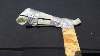
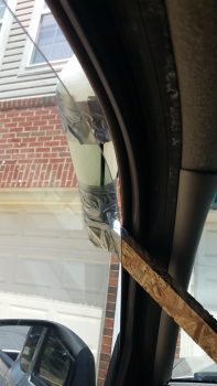
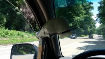
I had to run over to Andrews AFB to scarf up some money out of one bank to transfer to another bank for my upcoming purchase of the GRT EFIS I ordered under the discount that GRT offered for Sun N Fun 2017.  Since Andrews requires some Interstate/Freeway/ Motorway driving, I decided to test out my ventilation/heat system ram air inlet.  So I drilled a couple of holes into some chip board and then zip tied the inlet to the board.  Then I duct taped the zip ties to ensure they wouldn’t slide off.

I think it’s ready to go!

I then tested it out a bit in my driveway to ensure I wouldn’t kill, maim, hurt or embarrass myself . . . or anybody else for that matter.

I quickly realized from messing around with it above, that the inlet needed to be straight into the wind as best possible, but the angle for the rest of it really didn’t matter. Regardless (or “Irregardless” for Joe Coraggio!) at around 65 mph I was getting pretty good airflow coming through.  But then when I would push my hand up against the outlet I could pretty much shut down the flow.

So, quick assessment is that it seems to have decent airflow, but not good pressure.  And in this game sports fans, pressure is what it’s all about.  Looks like it’s back to the drawing board on this baby!  [Plus, I’ll do some more detailed testing . . . I got some ideas!]

After arriving back home I quickly got into the shop with the intent of getting the 2-ply BID base reinforcement layup for the oil heat pump mounting bracket layup glassed onto the aft side of the GIB seat.  I sanded down & prepped the area for the layup.

Then I prepregged 2 plies of BID, measuring 3″ x 8″, and wet it out with MGS 335 and fast hardener.

I then glassed in the 2-ply layup and peel plied it.

Here’s another shot at an angle to help with the exact orientation of this layup.

While the oil heat pump mounting bracket base reinforcement BID curing I then trimmed up the heat exchanger top duct piece.

I then test fitted the heat exchanger top duct piece back on the heat exchanger.

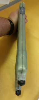
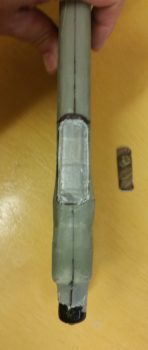
With both top & bottom ducts glassed, I could then verify the exact spots where the heat exchanger top & bottom inlets would go, given their dimensions match the ducts’ dimensions of 0.75″ x 2″.

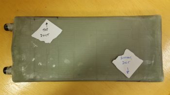
Again, for better understanding where the heat exchanger ducts are located, I identified them with a couple pieces of paper.

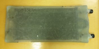
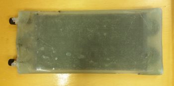
I then took a few minutes to mark up the lines along the entire perimeter edge of the heat exchanger cover to split the case in two and remove the heater core with all its protective tape, etc.

First though, I cut out the heat exchanger duct inlets on both the top & bottom (inlet & outlet).

After a fair amount of pulling, prying and practicing my “How to converse with Sailors” speak . . . and not to forget the requisite injury, I finally got one side off of the heat exchanger core.

Following the shampoo mantra . . . ok, the “repeat” part . . . I was finally able to get the other side pried off as well.

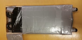
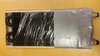
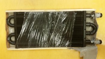
I then got to work deconstructing the protective barrier that Stacey had helped me construct (could this be why it was so difficult to remove?!  . . .  just kidding!).  I took a fair number of pics on this process since I didn’t take any as we applied the protection before.

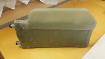
Here’s the final protective tape ensemble with the top & bottom 1/4″ wood caps that all served to protect the heat exchanger core while it was completely covered with glass.

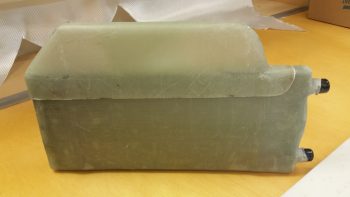
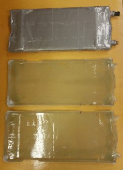
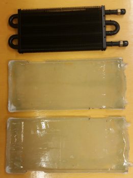
Finally, here’s the heat exchanger core with the two halves of the heat exchanger cover.

I then set the heat exchanger into one of the halves of the cover.

And then checked the fit of the heat exchanger core inside the cover.  Ahh, it’s awesome when a plan comes together!

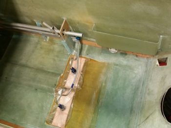
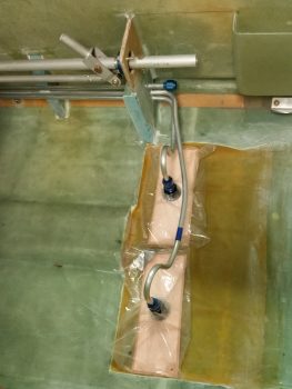
Although I had mounted the oil heat pump to its mounting bracket much earlier in the evening, my last official build task of the evening was to flox and glass the mounting bracket to its location on the lower aft side of the GIB seat.

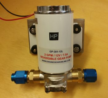
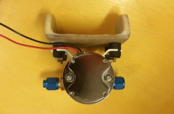
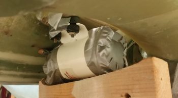
Before I get into that though, here’s a good shot (aft side) of how the oil heat pump will attach to the mounting bracket.

I pulled off the fittings and taped up the exposed areas of the heat pump as it sat on the mounting bracket.  I’m floxing & glassing the mounting bracket into place with the oil heat pump mounted to it to ensure clearance for the pump on both the forward and aft sides.

Although my off-center pic makes it appear more askew than it actually is, I must admit that during the initial mounting process of this thing, it did end up skewed off center about 0.070″ and is higher on one side by about 0.030″ . . . but that’s why we call it the hell hole right?! (As I told Dave Berenholtz: “Loaded up with flox on the edges of course this guy was like trying to balance a fish on a greased hard boiled egg!”)

I do have one more set of BID tapes to do on the bottom after the 2 sets of outboard vertical, 2 sets of inboard vertical, and 1 set of topside horizontal BID tapes cure.

I took this shot at an angle for as good as view as we can get of the side layups, in the hell hole and all!

The layup schedule I used was a 3-ply BID tape on each outboard vertical junction (the foam tabs & seat back), with a 2-ply BID tape on the inboard vertical junctions (inside surface of foam tabs & seat back), and a 3-ply BID tape on the horizontal junction (1/4″ plywood bracket & seat back).  Tomorrow, I’ll do a 3-ply BID tape across the bottom intersection with the seat back.  Moreover, the 2-ply vertical junctions have a lot of overlap in the interior corners, thus there’s a good amount of “5-ply” BID in the corners.

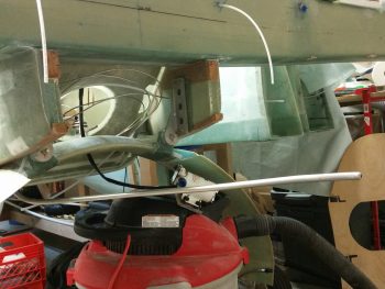
Finally, I wanted to show you all how I secured the pump/bracket assembly in place while I floxed & glassed it up.  What you can’t see in this pic is that the wood support is actually sitting atop my large shop vac.  In addition, If you look closely you’ll see that I taped 2 stir/ popsicle sticks on the front of the pump as a standoff pad so I could then just feel if it was pressed firmly against the fuselage bottom at the front and then concentrate on the aft side for clearance with the landing gear bow.

Tomorrow I’ll continue to work on the oil heat system ductwork, heat exchanger and finalizing the oil pump mounting bracket install.


Chapter 22/24 – PTT & Ducts

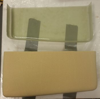
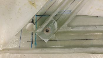
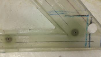
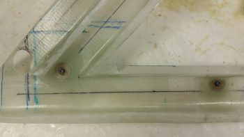
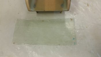
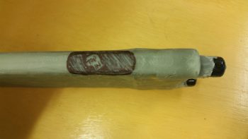
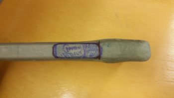
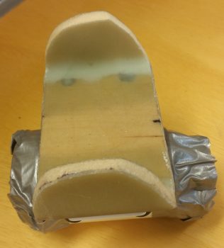
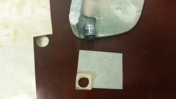
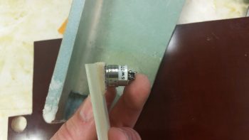
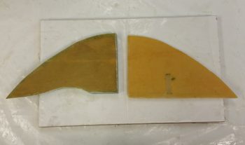
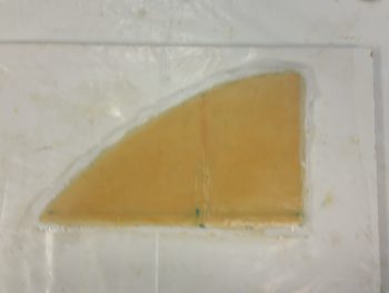
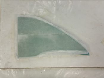
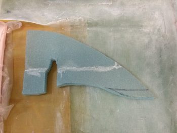
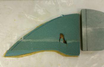
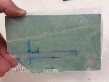
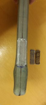
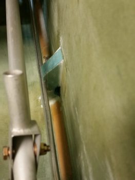
I started out today working on the GIB PTT button configuration & construction of a front plate for both the GIB PTT button and GIB headset jacks, all which will reside on the front of the left GIB armrest.  It may be a bit hard to tell, but the greenish blob coming down from the top of the pic below is the front of the left GIB armrest.  Top of armrest is to the left, with the PTT button resting in the notch I created for PTT button clearance.

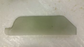
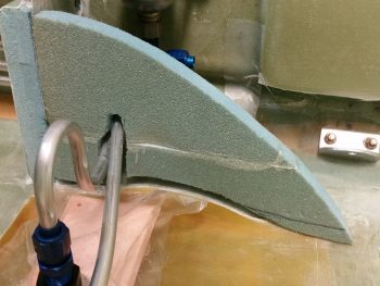
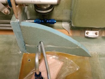
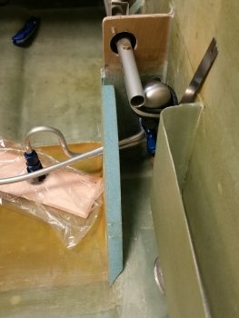
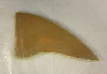
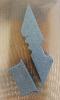
I positioned the PTT button notch where it is to get the PTT button as far up into the inboard corner of the armrest front face for easier “mashing” of the button any time the GIB is going to use it.  However, to stay clear of the PTT button being inadvertently pressed or an open mike situation, I’m recessing the button so the top of it is just below the face of the armrest front face.  Thus, at the center bottom of the pic is the piece of 1/16″ G10 I cut as the armrest front face cover plate, and in the corner where the PTT button will go, I notched it and shaped a piece of Divinycell foam with a 1/2″ diameter hole for the PTT button to sit in.  I 5-min glued the foam piece in place, then when cured I radiused the perimeter edge of the hole.

All this is sitting on a piece of 1/4″ phenolic which I drilled a 0.609″ (39/64″) hole into for the actual securing of the PTT button as it’s press fitted into this hole with some Silicone RTV to lock in nice & tight.

Since the left armrest front tapers aft at the bottom, I tapered the foam PTT button recess housing so that the PTT button would sit parallel with the top of the armrest for clearance on the internal side of the armrest.  Here you can see the PTT button set in place where it will get mounted.  If you look just forward (left) of the ID label sticker you can see the wider 0.609″ flange that will get press fit mounted into the phenolic.  The phenolic piece will of course get floxed to the aft side of the tapered foam recess housing.

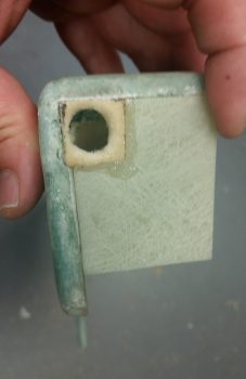
I then tested the fit of the assembled armrest front face piece in the notched corner I created in the armrest.  When finished, this front face piece will be an integral part of the sidewall bracket that remains on the fuselage sidewall when the armrest is removed.

I had to do some very light sanding after I drilled the 0.609″ (39/64″) hole for the PTT button to fit, which it did with a reasonable amount of force. Perfect.

Again, the physical mounting of the GIB PTT button will be in this 1/4″ phenolic block piece that itself will get floxed to the aft side of the foam recess housing that is attached to the front face piece.

I then cut out the phenolic block and trimmed it up.  I then mocked up the PTT button secured in the phenolic block, set in place where it will attach to the foam button recess housing, all with the front armrest face piece set in place.

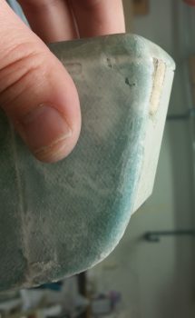
Another shot of the recessed PTT button in the left GIB armrest front face piece.

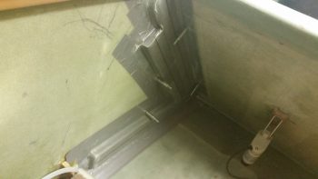
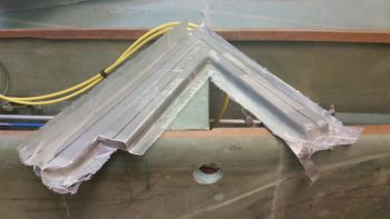
I then started back working on the GIB area heat & fresh air ducts that I laid up last night. My first task was to drill some 3/32″ holes into the flanges and install clecos to ensure I would later have the correct duct alignment when remounting the ducts back in place.

I then removed the clecos and fought for a good 30 minutes to get this ductwork assembly off of the interior fuselage sidewall . . . .

. . .  notwithstanding major puncture wounds to my finger and thumb and a fair amount of blood!!!  Literally blood, sweat and tears in building this plane!

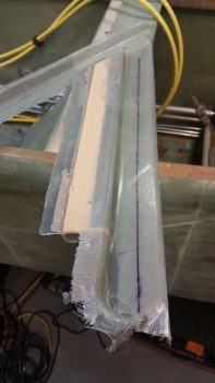
I removed the foam & tape for both the main air feed and the horizontal GIB lower air feed, but the air feed that goes back up top for the GIB high air feed I couldn’t remove without a lot of difficulty unless I trimmed the glass flange that will secure the shared duct wall with the main air feed.  This flange is from the main air feed and had I not subsequently glassed the adjoining parallel GIB high air feed duct right next to it, it would have stood on its own as a “normal” duct without being integrated into a 2 channel duct (or 2 separate ducts sharing an internal wall).

Well, I trimmed down all the flanges and was able to remove the foam from the GIB high air feed duct.  I didn’t weigh this ductwork assembly but it is super light, as one could imagine with it being just a couple plies of UNI.

I then clecloed the air ductwork assembly back in place after cleaning up a few spots on the internal fuselage sidewall.

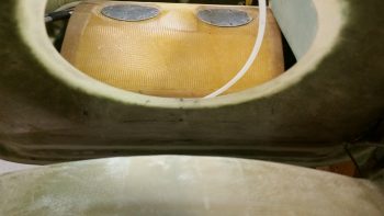
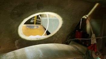
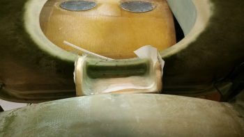
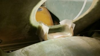
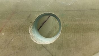
I snapped this shot of the main air feed as seen from the external fuselage side, through the ram air inlet, expansion chamber and transition tube hole.

Starting tomorrow up until mid-week will be light build days, if I get any building done at all, since I have Independence Day celebration activities, out of town visitors and get-togethers, etc.


Chapter 21 – Glassing sump walls

I started out today by pulling the peel ply and trimming up the edges of the layups on the wall sides that essentially make up the left sump tank, left & middle walls.

I then promptly glassed the right side of the middle wall, or sump rib, with E-Z Poxy to get it curing.

I then glassed the outside of the left sump wall using MGS, since this wall will not be in contact with fuel… hopefully!

When I did this layup, I also glassed a strip of BID on the bottom of the GIB right armrest storage pocket going to the sidewall.  Once cured, the GIB storage pocket will be glassed in once and for all.

I then marked up and did an initial cut on the right side wall to start the trial & error process of getting it to fit.

Here I’m about halfway through the process of fitting the right sump wall to the sump / fuselage floor.

And here’s when I finally got the shape along the bottom of the sump right wall dialed in.

Here’s an aft shot of the fuel sump’s right wall. Note that you can also see the fuel pulsation damper mocked up in these pics as well.

Once the shape of the right wall was good, I glassed it with a ply of Kevlar first, then a final ply of BID, just like I did with the inside layups of the other walls that make up the exterior perimeter of the sump tank.

One thing I was going to account for that slipped my mind until after I hurriedly glassed the interior side of the right sump wall, was that this wall needs to be a bit shorter due to it butting up against the back side of the right front sump wall extension.  I was so dialed into getting the difficult shape on the aft side of the wall completed, that I missed the front edge needing to be back 0.55″.  Since I had already configured the right side wall, I was going to merely trim the aft edge so it’s profile would match the other 2 walls.  But again, I jumped the gun in glassing the right sidewall so I didn’t get it done.

Fast forward many hours later, and I marked the left wall with 0.55″, aligned the two sides and then marked the aft/top of the right sump.  I trimmed the right sump wall immediately after this pic was taken.

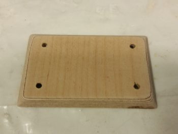
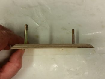
As the interior layup of the right sump wall was curing, I decided to knock out making the oil heater pump base.  I started with the 1/4″ Finnish birch plywood plate I cut out the other day.  I rounded over the edges and then drilled 4 x 3/16″  holes.

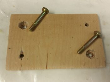
I then marked the heads of the only 2 AN3-12A bolts I have onto the back of the mounting bracket and dug the wood out to keep the bolts from spinning.

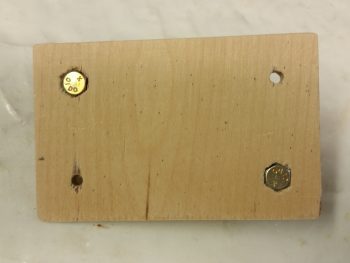
The bolt heads are flush with the bottom, can’t spin, with still a good amount of wood to keep them in place.  Still, this plate will get about 5 plies of glass to hold it in place.

Here’s a side view showing the bolts in place.

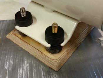
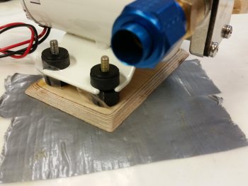
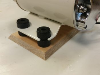
Since I didn’t have any more AN bolts, and I wanted to get this mount finished, I stole the two 1-1/4″ bolts from the fuel pump and mounted them in the oil pump mounting base.  I then taped up the bottom of the vibration mounting pads, floxed the bolts in place and then set the oil pump in place over the floxed bolts.

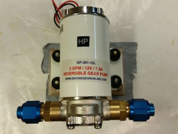
And here’s a couple more shots of the oil pump on its mounting base.

I then used the oil pump attached to its mounting base to figure out where in the world I was going to mount this thing in the Hell Hole.  Since I just recently discovered that it is best to mount it horizontally (interesting, but that’s what it says!) I found a spot centerline of the aircraft, immediately forward of the gear bow and just aft of the GIB seat.

This all ties into the sump in that before I glass the front side of the fuel sump front wall, I need to know if I’m going to mount the oil heat line fittings into the LEFT sump front wall extension.

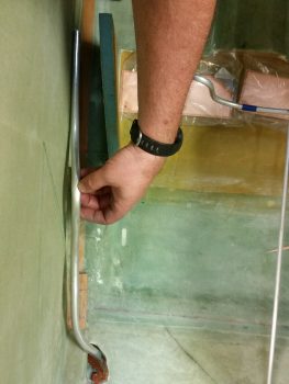
To figure out my oil heat oil lines, I needed to make some.  So I did.  I made the feed line that feeds the oil to the heat exchanger from the oil pump.  It all looked good on the top side . . .

. . . as you can see here . . .

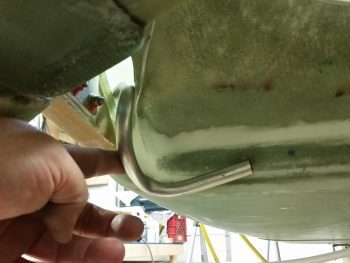
But since I don’t have a 1/2″ tube bender, I resorted to a spring kit for bending the 1/2″ tubes.  The spring works well enough on simple bends, but it just can’t handle really tight turns without crimping or flattening the tubing — as you can see in this real tight turn to the right.

I’ll assess further, but right now I’m thinking at least the oil feed line will most likely need to be a braided cable to provide me the flexibility that I need.

With that, I then made up an oil return line.  Since it doesn’t need to make a hard right turn to get to the oil pump, I didn’t think this one would have as much of an issue as the oil feed line.  And it appeared not to.

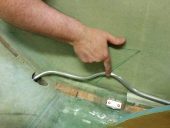
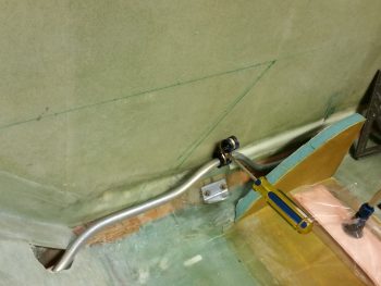
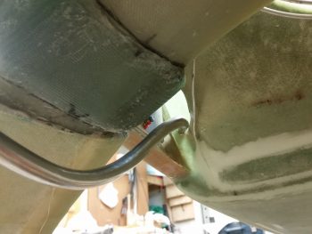
One interesting point in the pic below: I played around with the spacing and tubing run for a bit before deciding on exactly where I wanted the Adel clamp to be located to hold the 2 oil lines (feed & return).  Well, I reached into my pocket to get my trusty Sharpie, but, uh, no Sharpie.  So, I picked up a small Phillips screwdriver and gave it a nice sharp rap to make a mark…. well, it was a bit harder than I thought and it made a nice dent in the wall. So, another wiggle and another rap, and in she went…. I guess this will be a RivNut hardpoint vs a Clickbond!

A shot of the oil return line from below.

For now I’ll just count the oil return line good, and then later when I finalize the firewall configuration I’ll cut the oil return line and terminate it with a fitting.

Tomorrow I’ll continue working on the fuel sump.  I’m hoping to have it done in the next few days.


Chapter 16/21 – Uphill slog . . .

This morning when I happily went down to check out my layup, I didn’t stay happy very long.  As I was ripping off the peel ply, which is admittedly one of the best ways to start out a morning, a couple of areas still seemed a bit soft and not fully cured.  This was not really what I was expecting since I had used fast hardener.  Ironically, I had just had a discussion within the preceding days on fast hardener, as I extolled its virtues.

There is of course a possibility that I jacked up the ratio, but I am usually pretty good at ensuring those are correct.  Regardless, I decided to cook it for a while and set my sights in at a good post cure temp: 140° F for 4 hours.  Over the next couple of hours I checked various spots and never had the IR thermometer go past the mid 150° area, and only in a couple spots.  And I was checking just about every area in each heat lamp’s path (more on this below).

Besides the heat lamps, in this pic below you can see that I glassed the aft side of the GIB armrest storage pocket with 2 plies of BID.

Here it is a bit later after it cured.  Note the yellow spot at the front side.

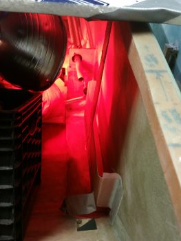
And below you can see the yellow spot again.  After establishing that my average temps on all the stuff I checked being in the heat area, including the sidewall and the storage pocket, were in the high 120s to high 130s, I ran out to grab a bite to eat and go to the store. When I checked the heat lamps a bit later I saw this discoloration.  I immediately checked the temp as I was pulling the lamp away, and it was 162.9°.  I also did a quarter test and could find no delamination.  Since a good portion of the yellow will get cut out when I open up the sidewalls for the baggage area, I’ll check the foam & glass again then.  But for right now, nothing seems odd except the color change.  Moreover, MGS 285 epoxy should have a multi-hour post cure over 170°.  I guess just that high of heat concentrated on that one spot over time caused the discoloration.

Moving on.  Note that the right front sump wall extension piece layup is complete!  The heat lamps did there job and the spots I was concerned about cured nicely . . . except one.

The area on the aft side of the foam at the bottom didn’t seem to be fully cured.  If this were slow hardener I wouldn’t have worried about it, but since the other areas were cured, this concerned me.  Now, it still looked like a solid layup, but the overhanging glass was just a bit too pliable for my liking.  I decided that in the 1 inch area that I would be laying up the BID tape for the outside of the right sump wall, that I would remove this glass.  Since I had laid up 2 plies over just the one on the sump wall extension, I broke through to foam in a couple spots.  No worries.  I’d rather have fresh foam for the next layup then putting good glass over some that is a bit suspect.  As for the rest of that layup, it’s in there and sticking, but I have so much other glass around it, I’m not concerned if its strength is a little less than normal.

In the right pic you can see the front side of the layup.

I wanted to show the access holes on the outboard side of this layup: the top hole is for the bundle of small wires that will traverse this bulkhead heading back to the aft areas of the plane.  The bottom hole is for the 2 big power wires to go through.

You can see that I also made the big power wire channel on the foam fuel line bracket as well.

So here’s a shot of all the layups I did last night, after I cleaned it all up. One good thing that happened is that weighing down the fuel lines worked.  The fuel lines are in the correct position and have no tendency to try to rotate upwards.

I then finalized my dimensions and shape for the fuel sump profile.  I took some scrap 3/4″ thick Divinycell foam and cut the pieces for the left & right sump walls.  I then micro’d the pieces together.

I then cut out the middle sump rib from 3/8″ Divinycell foam.  I loaded everything in the backseat for a quick mockup to see how it all looked & fit.

I then spent a good 25 minutes shaping the left fuel sump wall.

I figured out the fit on the middle fuel sump rib as well.  If you’re wondering why the bottom of the middle rib is cut, there is a technical term for that: it’s called being unfocused, not concentrating on the task at hand and having a major brain fart!  I noted on the left side wall that the base of it matches the base of the front wall.  I then inexplicably picked up the middle rib and had it cut and was putting it back in to check before I even realized the mistake I had made! Luckily, this is foam and composites, and it’s all easily fixed!

I started with the interior left wall and laid up the first ply, which is Kevlar.

I then laid up 1 ply of BID on the interior left wall (ply #2), and then –after reattaching the bottom strip– I laid up 1 ply of BID on the left side of the middle fuel sump rib.

I then trimmed the overhanging glass down.

And peel plied the layups.

Previously, I had laid up the forward side of the GIB armrest storage pocket with 2 plies of BID and a 1″ strip of BID down the front face of the foam fuel line bracket.  I then checked those to ensure that they were good to go.

Finally, since my garage is in the low 70’s I decided to put the freshly glassed sump wall pieces under heat.

Then I realized it was a bit too much heat and turned off one of the lamps and moved the sump wall pieces a bit farther away.

Tomorrow I’ll continue to work on the thigh support fuel sump and try to get this thing knocked out . . . hopefully a bit more error free!


Chapter 16/21/22 – Crossing the Rubicon

Today I crossed the proverbial Rubicon in my initial steps of the thigh support fuel sump by glassing the fuel lines into place, but more about that in just a bit.

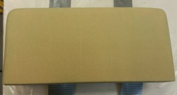
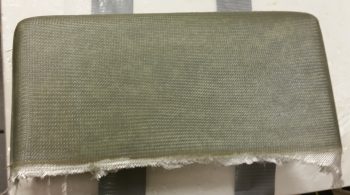
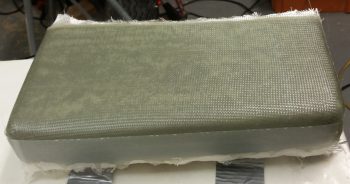
I started out today by trimming up the GIB right armrest storage pocket and removing it from the foam plug.  The pics below show both the front and inside of the storage pocket.
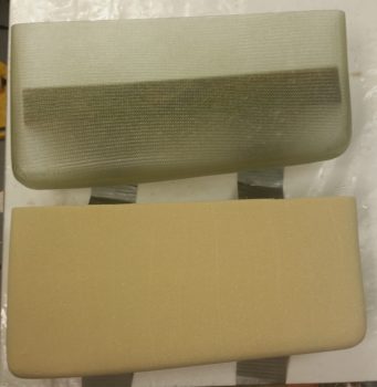
Here it is again, solo.
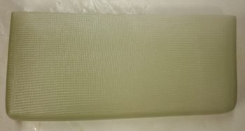
I then mocked it up in place to see how it fit.  I can say I’m happy with it, so it will soon be getting glassed into place so I know exactly how to route all my stuff around it!
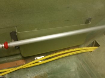
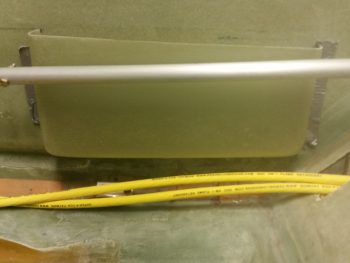
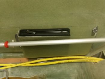
I had to lower it about 0.20″ for the iPad to fit, while in its case.  But mounting it just a tad lower also helps me with some lid ideas that I have.
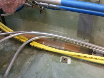
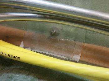
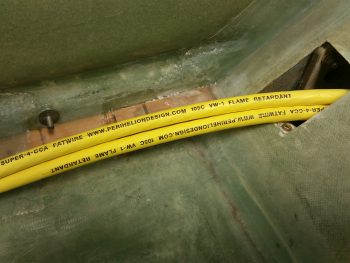
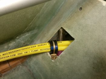
Moving on: I’m happy to report that the big pair of yellow cables are finally secure from the nose to the back seat.  Again, I will most likely have to secure them in one or two places in the Hell Hole, but beyond that, the task of routing these big suckers and securing them is complete!

Starting from the front part of the aircraft, here are the two newly mounted Adel clamp hard points in the pilot seat area: one Clickbond (forward) and one RivNut (aft).
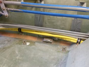
Here’s a closer shot of the Adel clamp Clickbond hardpoint.
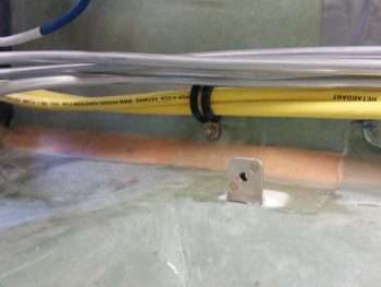
And a closer shot of the Adel clamp RivNut hardpoint.
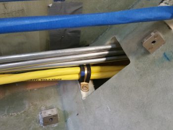
I also mounted a Clickbond just aft of the pilot’s seat as you saw in yesterday’s post.
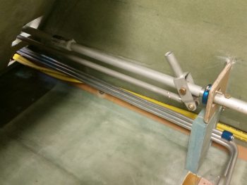
Here’s a clearer shot of that hardpoint with an Adel clamp mounted & in use to keep the big power cables secure.
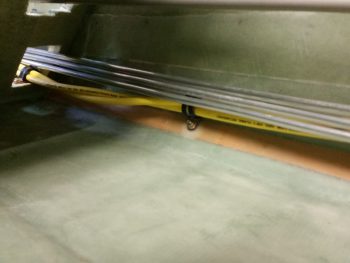
And here’s the RivNut Adel clamp hardpoint in the lower right side opening of the back seat.
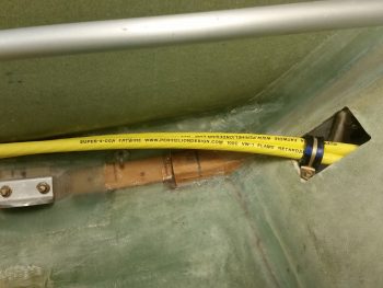
A little wider shot reveals the Clickbond that I floxed in place last night.
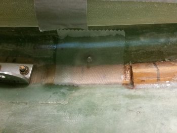
A bit later, I covered the Clickbond addition with 2 plies of BID and some peel ply.
I had an issue with the right side armrest today that needed some cutting to solve.  I simply couldn’t get the armrest mounted since the fuel lines were in the way.  I wanted to be able to mount the armrest since I was going to install the “map” pocket permanently to get a final idea of fuel line routing… and just to get it done!
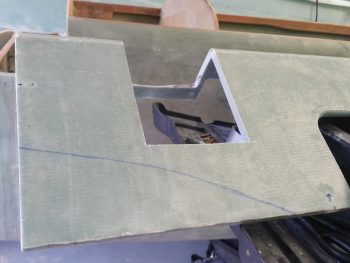
I taped in my 12″ flexible decimal ruler to get a good estimate of what the pilot thigh support ribs profile will be, and then cut it out.  Of course, I also wanted to get this area cut out in my continuing effort to get the pilot area sorted out as well to allow me to move on to the nose build.
I did flox in the map pocket at this point (final pic is below) during the same round of glassing that I did the big power cables’ “final” Clickbond above.

I then moved on with the prep to start glassing the fuel sump right forward wall extension piece to get it installed tonight.  This may seem like not such a big deal, but this piece is a major lynch pin to the entire fuel sump build.  Not only is it a part of the front wall –making the front wall a bulkhead by traversing from one fuselage sidewall to the other– but it also ties the sump to CS118 for added strength.  Finally, it secures the 3 fuel lines heading aft: one to each sump tank and the other to the engine.

One of my tasks was to make foam fuel line mounting brackets that –at least the bigger one– will need to be glassed in place when the fuel sump right forward wall extension piece gets glassed in.  I’ll most likely wait on the smaller bracket.  If you’re wondering why I went with foam and am using fiberglass to secure the fuel lines, I actually got the idea when I queried Nick Ugolini on it.

To use Adel clamps, I would have had to spread out the fuel lines much farther apart (unless I grouped them together, which was not something I was so keen on doing). Plus, the way the fuel lines go through the pilot seat back opening, they either have to have a significant bend or slant to get them to the sidewall an inch away to use the Adel clamps, or they still need some type of bracket built to provide the required standoff from the sidewall.

Yes, if my “map” pocket wasn’t installed I could have possibly drilled or removed the edge of the pilot seat back that sticks out from the sidewall, but I wouldn’t prefer to do that anyway . . . and of course it’s not an option in this case.  To be clear, I have been researching this topic online and talking to folks for over a week now regarding the securing of fuel lines, and when Nick mentioned this, it was simply an Aha! moment.
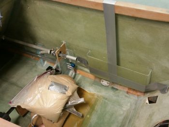
After a grinding few hours, here’s the final glassing-in of the fuel sump right forward wall extension piece. Obviously in the pic you can see where I’ve also 5-min glued the right armrest storage pocket.  As for the sump wall extension piece, I floxed it in place first after sliding the 3 fuel lines into the initial slot I created on this 1″ thick Divinycell extension.  I then used a clamp as a spreader to keep the extension piece firmly pressed against the right sidewall.  A bit later I had to remove the clamp for a bit while I mounted the foam fuel line bracket, but then it went right back into place.
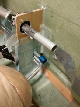
I used a couple of pieces of the original foam I cut out of the wall extension piece to place back under the bottom fuel line.  To lighten up the fuel line install I resorted to using flocro with a bit more micro than flox.  I flocro’d the bottom foam piece back into place under the  bottom fuel line, then had to add another 0.4″ thick foam piece to get the height correct.  I then slathered up the channel for the middle fuel line with flocro and added a 0.35″ foam spacer between the first and second fuel lines.  Again, I added more flocro and then another 0.40″ foam spacer between the middle and top fuel lines. Finally, I closed up the space above the top fuel line with another foam piece flocro’d in place.  The top fuel line has a tad more space between it and the middle fuel line to provide just a bit of clearance for the fitting that’s right there.
Once I knew the wall extension piece was securely in place, as were the fuel lines, I then carefully used sandbags to weigh down both fuel lines going to the Hydramats in an effort to have them cure in the correct position.  I of course am hoping that there is minimal spring back and that this works . . . to make it easier when mounting the middle and right side walls. Not a huge deal if they don’t, but again, it would make the upcoming wall installations easier.
Besides using 2-ply BID tapes to secure the sump wall extension piece to the right sidewall & fuselage floor–respectively, I also laid up 2-ply BID tapes between the CS118 mini-bulkhead and the sump wall extension, also on both the front and aft sides.
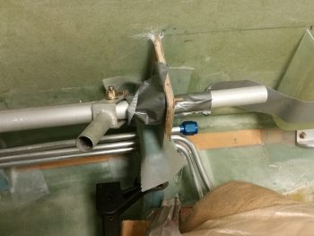
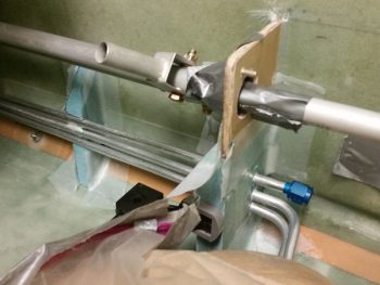
In the pic below you can also see the foam fuel line bracket that I floxed & glassed in place.  For this I simply used 1 ply of BID on each side.  After I ensure the fuel lines are in the correct position, tomorrow I’ll secure each fuel line in place with flox in its respective notch, then I’ll layup a 1″ wide ply of BID over the entire edge of the fuel line bracket, from floor to sidewall.  I’ll most likely mount the other fuel line bracket, and probably even get the fuel lines nice and situated, then mounted at the pilot seat bulkhead opening.
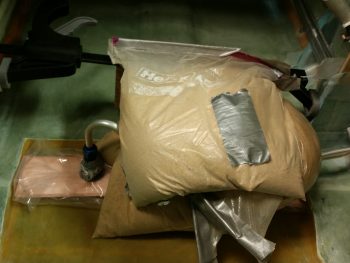
A few hours later after I finished the layups above, here’s the floxed in place and 90% cured pilot right armrest “map” pocket.  I ended up mounting it about 0.050″ lower than I had marked, which actually works out perfectly because there is literally no sign of the actual “map” pocket visible when the armrest is installed.
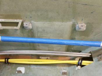
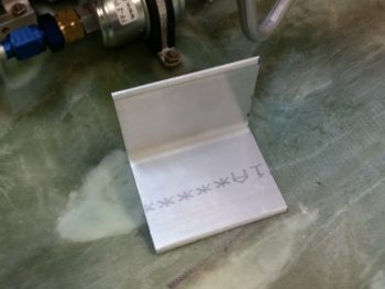
I actually did this early evening before it got too dark, but I placed it here in the blog for better topic flow.  I went out to my shed and pulled out the big miter saw to cut this 2.5″ x 2.5″ x 3″ wide 6061-T6 angled aluminum bracket piece for the initial fuel selector valve bracket.  This bracket will be the base for the “S” curve bracket that will attach to it. In turn, the “S” curve bracket will be what the fuel selector valve actually mounts to.  The position shown here is way low since I just have it setting there.  However, the left/right position shown is pretty much spot on.
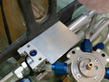
Here’s a shot of it free & clear.
Tomorrow I’ll continue to work on the thigh support fuel sump and should get the front side of the front sump wall glassed, and then actually get the front wall installed tomorrow night.  Then I’ll start working on getting the 2 side walls & 1 interior rib cut out, shaped and glassed.
 

Chapter 16, 21, 22 – GIB Prereq’s

Today I started out by trimming the right front corner piece of the fuel sump’s front wall extension.  I had glassed the aft side last night, and now I trimmed it up in prep for glassing a ply of BID on the front side.  I did leave the glass over the channel in the middle alone for now just to maintain a little bit more strength in the piece while handling it.
I then micro’d up the foam and laid up 1 ply of BID on the front side.
Something I didn’t mention from last night is that I took the small bit of left over epoxy that I had, whipped up some flox, quickly prepped 2 Clickbonds, and floxed them to the corner of the fuselage in a couple spots to secure the pair of big electrical cables going from nose to aft.  I also embedded a RivNut (not shown) in the pilot seat bulkhead, for an additional Adel clamp for these big battery cables.
So, before I mixed up the epoxy to glass the 1 ply BID layup on the fuel sump right front wall extension piece above (today), I made up two small 2-ply BID pre-preg setups with ~2″ x 2″ plies to secure the Clickbond assemblies that I floxed in place last night using the leftover epoxy.  I laid up a 2″x2″ 2-ply BID layup over the first Clickbond, which is located in the area below the pilot control stick.

Here’s a closer look.

The 2nd Clickbond lies halfway between the pilot seat bulkhead and CS118, aft control assembly mounting mini-bulkhead.  It also got a couple plies of BID.  As you can, I also peel plied both of these Clickbond BID layups.

Still using the same epoxy as the above layups, I whipped up some more flox to attach yet another Clickbond for the big battery cable pair, and also embedded another RivNut in the GIB seat bulkhead for the same purpose.  I know that I’ll need one more Adel clamp in the Hellhole for the big battery cable pair, perhaps two, but that will be it for securing these mondo cables up to where they either attach (-) or pass thru (+) the firewall.

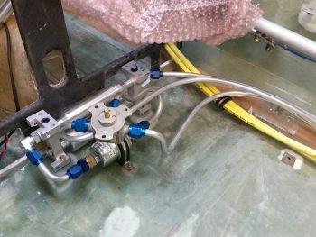
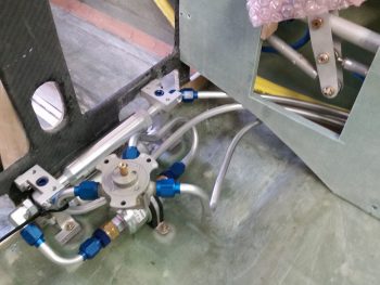
I realized that I was remiss in showing a pic of the fuel selector valve with all the fuel lines in place, so here’s a shot.  Also, to the right you can see one of the new Clickbonds.

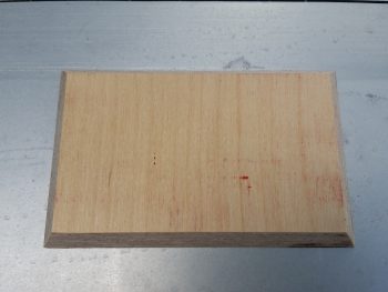
I then pulled my table saw out of the shed and cut a 1/4″ thick piece of Finnish Birch plywood for the oil heat pump mounting pad.  I also beveled the edges in prep for it getting glassed into place.

I then tried out the fit of the oil heat pump on its new mounting pad.  The 4 each AN3 bolts will stick through the pad –with the heads embedded in the plywood on the back side– to secure the oil heat pump.  In addition, before I glass all this I’ll sand the beveled edges of the pad to remove any sharp corners.

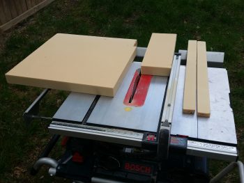
While I had my table saw out I took the opportunity to cut up some 2″ thick urethane foam for some plugs.  The 2 longer strips on the right will be plugs for the heat & air ducts, while the block in the center is the GIB right armrest storage pocket plug.  FYI – this storage pocket is somewhat like the “map” pocket in the front right pilot’s console, only much bigger.

I hate wasting dead space in this plane, especially since storage space is a premium in Long-EZs.  Since I have just a hair wider back seat bulkhead (around 0.8″), combined with the Cozy Girrrl’s Cozy style control sticks [which straddle the control tube vs. attaching just on the inboard side], I needed to move my control tube assembling inboard about 3/4″ if I wanted the configuration to match that of the plans.  All these minor mods served to create a significant gap between the aft control tube and the right fuselage sidewall.  A gap that I of course exploited to use as storage.

I had jotted down some initial configurations last night, and further dialed those in today to come up with a storage pocket measuring 12.5″ long x 1.7″ wide x 6″ deep (tapering up to 5.2″ deep on the aft side).

This configuration not only provides a fair amount more storage, but it also allows all the engine fuel feed line, main tank sump feed line, big power cables and a smaller electrical bundle to all traverse around or under it.

Thus, with my design good, and wanting to dial in the engine fuel feed line, specifically, I decided to go ahead and glass this baby up.

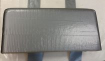
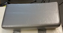
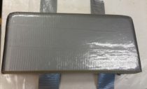
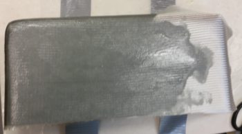
I started by taping up the urethane foam plug with silver duct tape.  For a smoother interior pocket surface after it has cured, I then followed that up with a layer of clear packing tape.

I used BID as the first ply down, followed up by 2 plies of UNI biased in opposite ~30° directions.  To add a little bit more stiffness than my “map” pocket, I added 1 more ply of BID that covers the entire side and about half of the bottom and each end.

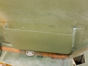
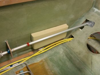
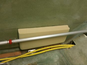
Here’s the glassed GIB right armrest storage pocket.

I then peel plied the bottom, front and back sides to allow for future glassing in place with BID tapes.

I then left it to cure as I went out for the evening.