Chapter 13/21 – In RV country!

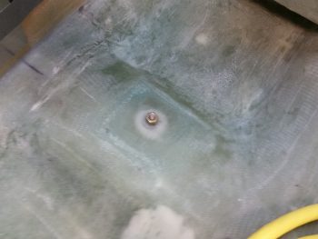
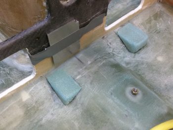
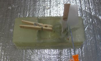
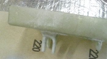
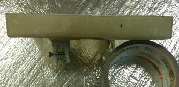
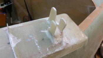
First thing this morning I pulled the peel ply off the fuel pump mounting pads.  There were a couple minor air bubbles but the layups looked good.  I cleaned up the peel ply strings a little before snapping this shot.
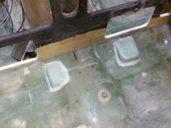
And then sanded the areas that I couldn’t easily apply peel ply to last night.
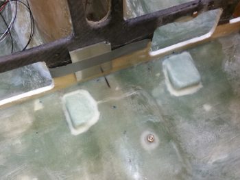
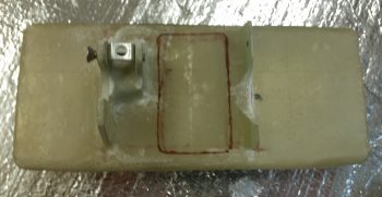
I then quickly checked the fuel pump fit on the mounting pads.
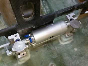
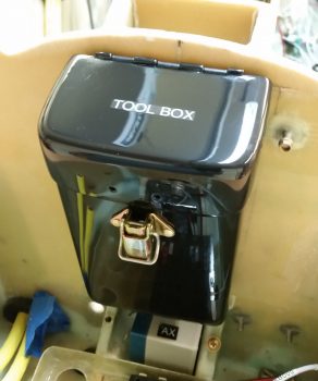
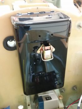
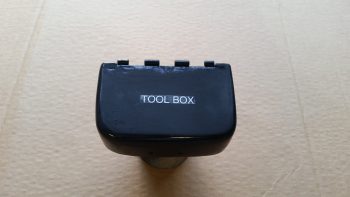
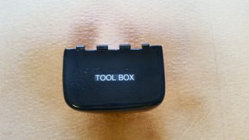
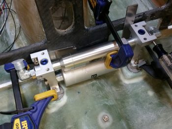
Before heading out on a 2-part quest I prepped & floxed the 2 larger click bonds in place onto the mounting pads, securing the fuel pump in its mounting position to keep the click bonds appropriately spaced.  I was heading over to my EAA Chapter 186 buddy & RV-10 builder, Jeff Karrel’s place for some help riveting the lower latch to the tool box, since he of course has all the big gun riveting tools required to do such a job.  The rivets on my lower tool box latch are just too low for me to get to with my hand rivet squeezer.
I also stopped by my local Village Hardware store to pick up some 1-1/4″ SS hex drive cap head screws.  Normally stores only have half-inch increments available after 1″ (then 1-1/2″, 2″, 2-1/2″, etc.) but behind all the other cap head screws they had a small box: 1-1/4″ length for apparently a previous special order!  Voila!  And they didn’t even have a price… but we worked out a price and I bought a couple and was on my way to Jeff’s in short order.

Jeff showed me his beautiful RV-10 build (that thing is HUGE!) and after about an hour of shooting the breeze we actually got to work.  Jeff pulled out a deep-necked pneumatic rivet gun and asked me if I wanted to do the honors.  I did, but I wanted him to do it so I could have yet another builder’s “mark” on my build as well!
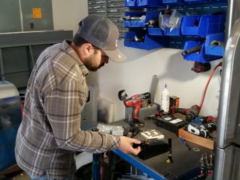
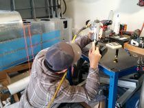
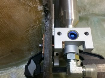
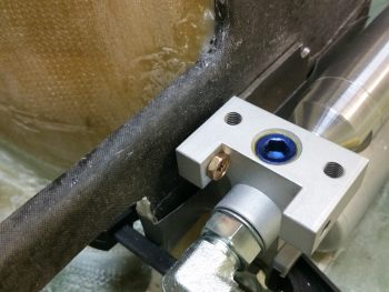
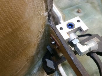
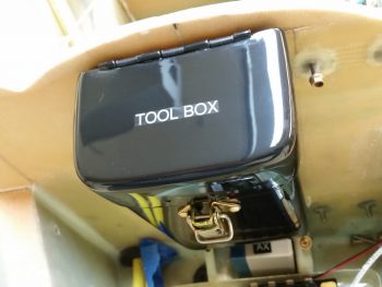
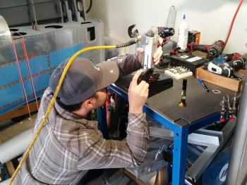
Here’s some action shots of Jeff driving the rivets on my lower tool box latch.  Also, you can see his incredibly clean RV-10 build in the foreground.  He is just finishing up riveting the tail section to the front fuselage… exciting stuff.
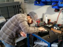
One more shot of Jeff driving home the rivets on my tool box . . . huge thanks Jeff!
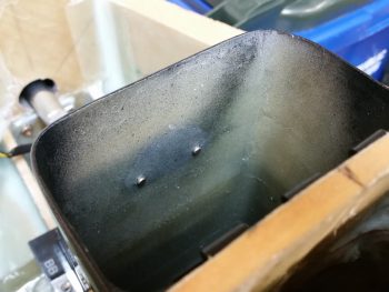
After another couple of hours talking shop with Jeff, I then drove home and set the tool box back in its proper spot.  I then grabbed a shot of the rivets Jeff set in place.  It’s all coming together!
I then cleaned up & prepped the 2 large fuel pump mounting click bonds for glass.
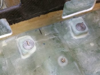
After adding a bit of flox for transition around the edge of each click bond, I then laid up 3 plies of BID over each one.  I peel plied the 2 layups and then took off to meet a buddy of mine for dinner and a movie (sorry, no pic of the peel ply on the layups).

Upon returning home for the evening I pulled the peel ply and cleaned up the layups.
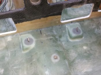
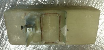
I then test fitted the fuel pump mounting on the freshly installed lower click bonds on my glassed foam mounting pads.  Looking good!  One small issue that I have is that the 1-1/4″ bolts are too long to fit in the gap on the fuel pump mounting frame.  I’ll have to drill out the aft-side mounting holes –which aren’t used here– to a wider diameter to allow the bolt head to fit and slide through to the other (forward) side.
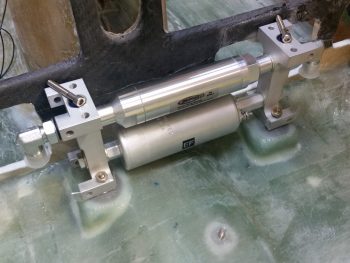
I then test mounted the fuel pump’s pre-filter to check its fit & placement.  Again, looking good so far!
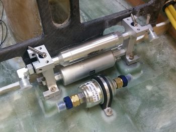
Hopefully tomorrow after I drill out the aft top mounting holes to fit the upper mounting bolts in place I’ll be able to report that the fuel pump is officially mounted!
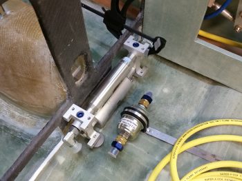
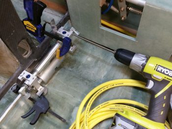
 

Chapter 21 – Mounting fuel pump & filter

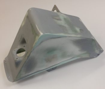
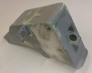
Today I focused on mounting the EFII fuel pump and its pre-filter.  I played around with the configuration for a bit before finally narrowing both components’ locations as shown below.

With the existing fillet at the bottom aft of the instrument panel –where it’s glassed to the fuselage floor pan– I needed to have a slight gap between the fuel body and the instrument panel.  I thought 1/16″ (0.063″) would do it at first, but it wasn’t enough and still caused the bottom of the fuel pump to kick out aft a little bit, not allowing for a true vertical install.  I tried 1/8″ (0.125″) but it seemed a bit too much.  I then scrounged up some 0.093″ scrap aluminum to test as a spacer and that did the trick.

With the position of fuel pump dialed into its final position, I clamped it and drilled the top 2 mounting holes into the lower instrument panel.

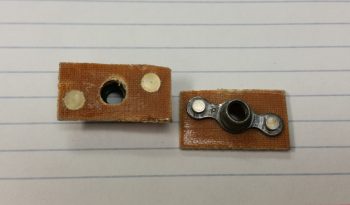
I then made up 2 K1000-3 nutplate assemblies with 1/16″ phenolic.

With my fuel pump positioned, I then fiddled around with the pre-filter before I finally figured out its final position.  I then marked the spot and 5-min glued a click bond in position (after I prepped the clickbond).

I then laid up 3-plies of BID over the Clickbond after creating a flox transition around its edges.

I also floxed in the left nutplate assembly and screwed an AN3 bolt into it to hold tightly in place while it cured.  Over on the right side, due to the drilled mounting hole being so low on the lower instrument panel cross frame (top edge of map box/lower edge of leg opening) I micro’d in a half moon looking piece of H45 foam in prep for 2 plies of BID on the front side, and 1 on the aft side.


If you’re wondering about the bolt head’s close proximity to the fuel pump frame, and how it can’t possibly turn, you’ve spotted an issue.  Tomorrow I need to pick up some hex head socket cap screws to allow them to turn in tight quarters.

I then decided it was time to roll up my sleeves and knock out the hour++ trial and error process of forming respective Devinycell wedges for both the right and left side of the fuel pump.  As you can see, these foam pieces will make up the mounting pads for the fuel pump frame’s “feet,” allowing me to bolt in the fuel pump frame on the lower aft sides (vertical bolts) and the forward side (left & right as well) using horizontal bolts.

After mocking up the fuel pump countless times, with a myriad of sanding with my Perma-Grit tools (still love those things!) to shape the respective pads, I finally got the shape and positioning I wanted with the pads.  Moreover, with the pads in place and the fuel pump temporarily installed, I could checked that there was a decent gap for the eventual mounting of the bigger sized click bonds for the aft side fuel pump mounting.

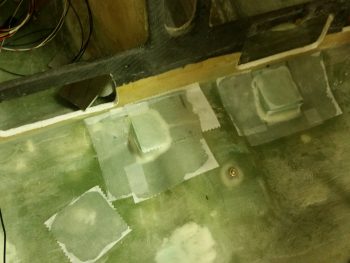
I then micro’d the foam pads in place and laid up 2 plies of BID over each pad.  Down in the lower left corner in the pic below is a small square ply of BID that I glassed in placed and peel plied (along with the pad layups) to patch a small divot I had put in the floor at some point… I still had a small amount of epoxy left over allowing me to do this.

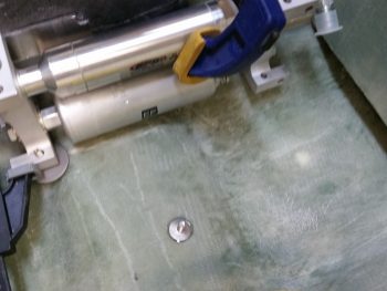
I also floxed the right mounting nut plate assembly into place (after I redrilled the hole) and held it in place with an AN3 bolt while it cured.

Below you can see a shot of the small curved piece of foam I glassed in place to help as a backer for the the right side fuel pumping mounting nutplate  assembly.

With that, I did one final check on all the layups, and called it a night.


Chaps 13/17/21/22/25 – Firing it up!

And when I say “Fire,” I’m not kidding . . . read on below!

Today I started out doing some planning and inventorying for my fuel system.  Since I’m going to make my new work demarcation line at the pilot’s seat bulkhead, going forward, then I needed to figure out my fuel system in real terms, not just in my head.  I drew out the fuel system on a white board and then did an inventory to see what I had on hand and to see what I needed to order.  I was fairly pleased that I had the majority of stuff I needed on hand, but will need to order about $35 in fittings from ACS.

I also did some research on the exact installation requirements for each fuel system component.  For example, on the Andair fuel valve I could clearly see that the big red selector handle needed to come off to install it, but I hadn’t even truly read the install manual until today to find out how to remove the handle, and install the unit.  I also had some questions on the FT-60 Red Cube fuel flow sensor that I eventually got answered on the VAF site.  In addition, I wanted to double check some info on the fuel pump.

After a few hours I was happy with my progress on the fuel system and was satisfied that I actually knew the direction I was headed with that system once again.

I then my sights back onto the Atkinson pitch trim system.  Having received my reamers via UPS this AM, I was ready to drill and ream a nice round 1/4″ hole in the elevator tube to mount the control arm of the pitch trim actuator.

First, I spent a good 45 min dialing in the new configuration and physical mounting of the pitch trim actuator by redrilling the 2 mounting holes in the mounting bracket.  Not only was I moving the entire unit aft a hair, I was also rotating the front of bracket down a bit more while the aft side dropped down some as well, but not as much as the front.

Once I got the pitch trim actuator assembly newly aligned, and the mounting hole in the elevator tube was ready to be drilled, I set up the control system within the plan’s specs with the elevators at neutral and the control stick at ailerons level, which is actually about a 5° stick grip lean to the left — again, as per plans.  I then drilled out the hole in the elevator tube and mounted the control arm of the pitch trim actuator.

Once I tested the newly realigned pitch trim system, the up trim worked fine but the down trim didn’t work at all.  Apparently, if you’re prone to moments of just being dumb, then you can expect issues like this!  Apparently, in my haste to get this pitch trim actuator in this bird, I forgot to double check its current position.  Since the actuator arm was all the way in, then when I threw the switch for it to push the elevators up, it did so with no issue. But then when I went the other way, well, by the time the actuator throw ended the elevators were merely back at level . . . and didn’t go down below the level line at all.

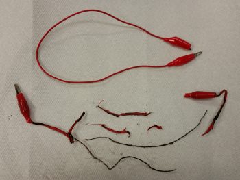
Another issue I had was just a little battery fire, or so I thought –after I removed the actuator to set it at its midpoint position– as I was coming around the nose and had moved the actuator power wires.  Well, as I rounded the nose I could see a bit of fire right on top of the battery.  Not sure what was actually burning, I yanked the wires off the battery and kicked it across the floor so if it decided to do something violent I had the fuselage between me and it.

Well, the fire went out immediately, but there was a good bit of smoke.  Apparently one of my patch cords shorted out and literally blew apart and started burning.  It’s interesting that none of the mil spec wires had any issues, but a couple of the cheaper leads were destroyed.  A few minutes later I felt the battery to see if it was warm, and it wasn’t.  I then checked voltage on it and it was a bit low at 12.59 volts.  But then again, I haven’t charged it in a few weeks and I have been using it a lot.  An exciting little sideshow to be certain, but with that out of the way, I got back to the task at hand.

After about 10 minutes of having the garage open and a fan turned on to clear out the smoke and smell from the burning battery wires, I went to work to fix the actuator configuration by simply taking the actuator out of the nose and extending it until it was half out (1.5″ out, with a 3″ total extension).  I then remounted it, verified and reset the control system to specs, and the drilled the new hole.  When I tested it the second time around it worked like a champ (see video below).

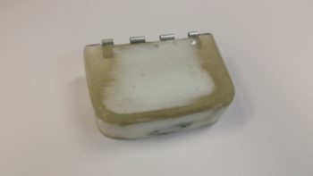
With the pitch trim actuator install taken care of for the most part, I then turned my sights back onto getting some of these painted parts knocked out.  I wet sanded the tool box lid lightly with 500 grit sandpaper, then 1000 grit and finally 1200 grit.

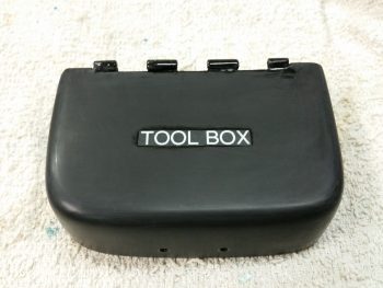
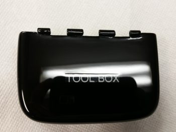
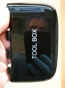
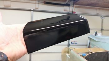
As I buffed out the tool box lid I was also uploading the lengthy video above.  It took a little over an hour total to buff out the tool box lid by hand.

Again, after the Ultimate cutting compound application, I then wrapped up the tool box lid by hitting it with 3 rounds of Meguiar’s Ultimate Polish.

I then set it on top of the tool box body.

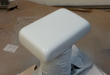
Finally, my last task of the evening was to wet sand & Simple Green wash the GPS antenna cover.

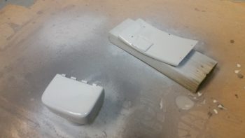
After I prepped it for more paint, I hit with 3 coats of white primer/paint to cure overnight. This antenna cover will not be a gloss color, but rather either semi-gloss or even flat.

I’m heading into the weekend tomorrow and have plans tomorrow afternoon on, but I will continue to try at get all the nose components installed –including the now prerequisite pilot cockpit area– to allow me to build the nose top.


Chapter 22 – Pitch Trim System Mounting

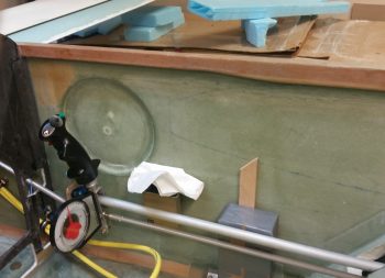
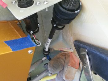
I started off today checking the clearance for both sides of the pitch trim actuator and realized that in extreme forward and aft stick situations, the elevator control tube had its motion limited by the corner panel reinforcement plate that I added.  I marked the corner plate and then Dremeled out the offending area (camera side of the magenta line).

As you can see, before actually starting I wedged a leather glove in place above the control tube to keep from inadvertently nicking it with the Dremel.  Before I did any cutting, I also taped a spare piece of small angled aluminum to the blue control stick cable to protect it as well.  Of course, I forgot to get an after pic, but it’s pretty much a shot of everything from the magenta line out simple not being there.

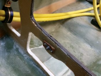
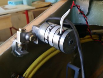
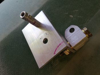
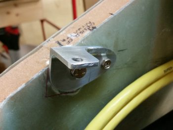
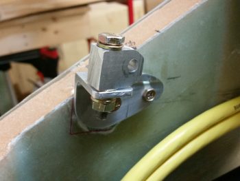
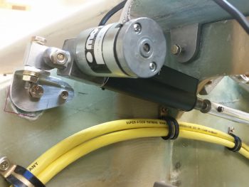
So here’s a shot of the first significant mod of the pitch trim actuator bracket, which I’m calling “Mod 2”.  Note that I pulled the swivel bracket from between the sides of the U-channel bracket and mounted it up top.  This really got the pitch trim arm up where I wanted it, at a line above the big yellow power cables.  Also, I did play around some with the bolt hole positions before moving on to “Mod 3”.

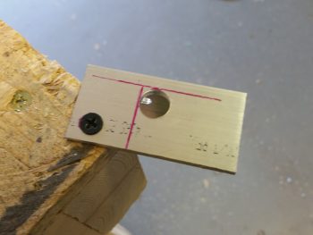
For Mod 3, I redesigned a whole new 1/8″ 2024 aluminum bracket.

I drilled the mounting holes and then removed the area on the top plate where the actuator will fit into.

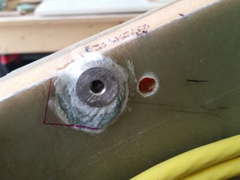
I then mocked it up and marked where a second hardpoint will go into the sidewall.  This will help alleviate the stress on the front bolt from the forward and aft pushing & pulling action (which places either forward or aft twisting action on the mounting plate).

I then located and drilled the hole for the second pitch trim actuator mounting hardpoint.

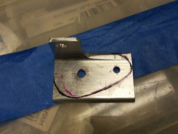
After the second pitch trim mounting hardpoint was cured, I then pulled the plate and marked it up for cutting to reduce its footprint and shave off a little weight.

Here’s the pitch trim actuator mounting bracket reinstalled.  Note the second, smaller, bolt holding the aft side of the bracket securely.

I then reattached the swivel bracket atop the sidewall mounting  bracket.

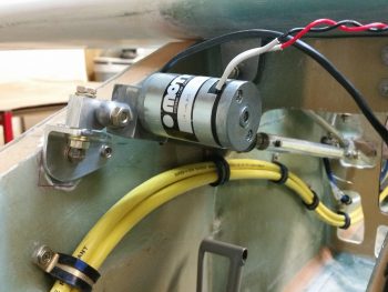
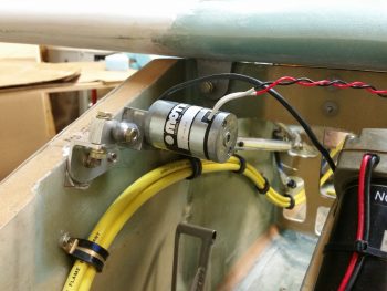
And finally, here are a couple of shots showing the installed pitch trim actuator unit.

And one more shot that provides a good view of the mounting bracket assembly.

I thought this post would contain overwhelmingly good news on my pitch trim actuator installation, but it looks like more mods will be required.  As you can see in the video, since the nose sides curve inward at a fairly decent rate from the instrument panel forward, then aligning the pitch trim actuator in line with the elevator control tube is simple impossible to do in a Long-EZ (it may be doable in a Cozy, I don’t know) . . . at least this Long-EZ.

So, as you’ll see in the video, after trying different ways to mount the aft end of the pitch trim actuator arm to the elevator control tube, I eventually had to settle on mounting the rod end onto the inboard side of the control tube clamp bracket that Marco made for me.  Unfortunately, that created another issue:

Obviously I still have some more work to do to dial in the pitch trim unit so that it will be fully functional as designed . . . thus, the slog continues!

Chapter 13/22/25 – Electrons & paint

Well, I stated yesterday that I was planning on working on the taxi light actuator extend & retract system . . . that didn’t happen.  Today I focused on working to finish up the new nose gear system wiring.

I continued from where I left off last night and started by tying in the P2 connector to the mix.  The P2 connector resides at the right midpoint mounting bracket on the NG30 cover, and was the original connect point of Jack W’s AEX unit.  Now it has zero connections for the AEX function and is merely a break point for the wiring harness for making the removal of the NG30 cover EZ with just P2’s removal, and P0 on the RCU box. Besides an E-Bus fed power wire to the up/down limit switches, and an RCU box ground, the remainder of the P2 wires all deal with either LED indication of gear up/down transit, or AG6 warning annunciation for gear up and down.

I started by terminating the wires coming out of P1 into P2, installed the wires and closed up the A-side of the P2 connector with a cable clamp.  I then selected and terminated all the wires to the B-side P2 connector, and installed the cable clamp (center top of pic).

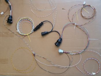
Also, as you can see I (prematurely) mounted the AEM D-Sub 15-pin back shell (chrome silver-looking connector).

I moved the pic below up for comparison to the one above.  As per Marc Z’s plan, I needed to solder a 560 Ohm resistor in series for the Laser Altimeter but forgot while I was building the aft side wiring harness for it.  No big issue, sez me, I’ll just solder it in so it’s nice and tucked away inside the AEM 15-pin D-sub back shell (ID: Connector J9).  Well, you got it… I forgot again!  So I disassembled the back shell and spent a good half hour soldering one tiny 560 Ohm resistor in place.  I insured I had heat shrink on the wire before I did my final solder, so was able to get a nice solid heat shrink piece in place over the soldered-in-place resistor & junctions.  I stuffed all the wires back into the AEM D-Sub back shell, closed ‘er up and was back on track.

In addition to soldering the resistor into place on the AEM J9 side B connector, I also terminated every wire that came out of this connector.  Six of 15 wires out of this D-Sub connector go to the RCU P0 connector, so I terminated those and plugged them into P0.

I also added another connector player into the mix at this point since this whole system is obviously controlled by the throttle mounted gear up/down switch.  This meant running, terminating and mounting the gear up/down switch wires into the Throttle handle P4 connector (black & white twisted pair to upper left corner in pic below).

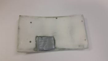
After the first round of wiring on the new nose gear system above, with its subsequent & requisite diagram updates, I touched up the aft NG30 cover with just a couple dabs of metal glaze and gave it another good epoxy wiping to eliminate some more pin holes that popped up.  As you can see, I also slathered up the tool box lid to hopefully remove the minor surface irregularities that have been plaguing me in trying to get this one small part painted!
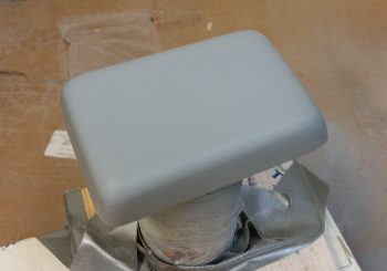
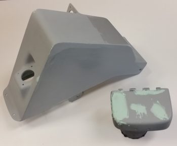
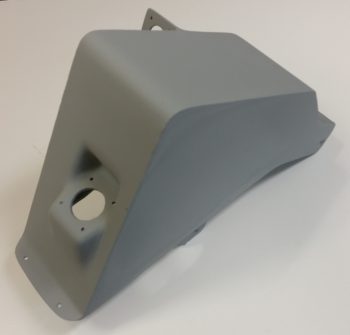
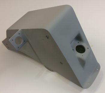
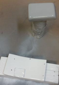
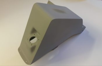
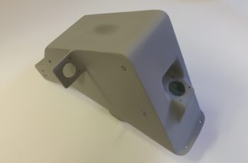
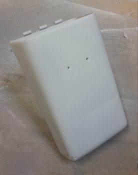
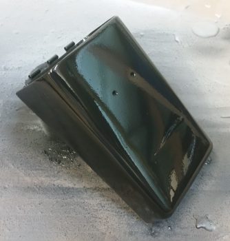
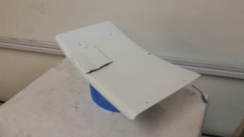
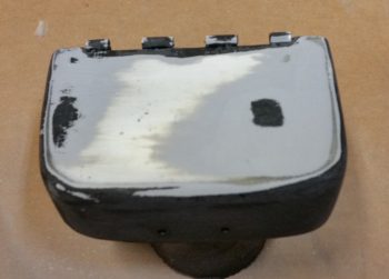
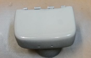
In addition, although taken quite a number of hours after I applied 3 coats of off-white primer, here’s a shot of the GNS480 GPS antenna cover that will sit atop my headrest. Since I had to go to town on it to remove the thick layers of my boat paint trial application, it too will need some TLC to smooth out the finish on it as well.  Regardless, the color you see below will pretty much be the final color for this piece.

Tomorrow I’ll round up all the correct color/size of wire to cut, terminate, and mount it into the RCU P0 connector.  This will finish up the wiring harness for the new nose gear.  I’ll also continue finishing the nose components (and the GPS antenna cover).  Finally, I do hope to sneak in some work on the taxi light actuator extend & retract system configuration.  Regardless, although it seems like it’s baby steps on a bunch of nit-noy stuff, I am getting closer –inch-by-inch– to knocking out my self-imposed to-do list before getting back to the “main” build.


Chap’s 13/22/25 – Sand-prime-paint, repeat

I started off today by sanding down the top of the tool box lid with a straight sanding board with 80 grit on it.  I took it down until it was level and then hit the top & sides a bit more lightly with 180 grit.  I then washed it up & prepped it for a reapplication of high build primer.

I tossed around the idea of just going back in with paint, but it’s going to need a couple of rounds of TLC for the surface to be ready for paint.  That being said, I just hit it with one medium coat and called it good.

I then spent over 1.5 hours on prepping the aft NG30 cover for final primer.  The top left forward corner and lower left edge where it meets the NG30 plate were both a bit shallow, so I added in some glazing putty to fill it in.  I use the same stuff I did when I was building my custom motorcycle: Evercoat’s Metal Glaze.  It works like a dream… mixes fast and creamy, and fills very smoothly.  It also sands great as well.

I filled one depression on the right side of the cover, and the upper forward corner area on the right as well.

After sanding down the filler and blending it in, I then hit the aft NG30 coat with 2 more coats of primer.

If you look closely, you can see the bleed through of the filler to the surface.  I’ll lightly sand the cover one more time, then most likely hit just these areas again with primer before final paint.  It may seem like I’m being overly fussy, but just like in composites, the prep in painting is really what takes the longest.  The final few coats of base coat (or final here) is the culmination of a lot of prep.  I just want to get this finish dialed into an acceptable level (yes, it doesn’t help that I’ve done body work & painting before… in that I’m sure it makes me a bit more picky) so every time I look at it I don’t get a gnawing feeling that I left a half hour more work on the table to clear up a minor, yet glaring, imperfection.

I was going to use a white primer on both the NG30 covers, then simply clear coat them. However, the primer I picked up was just not bright enough white for me to go on as the final color.  So while I was out I picked up some actual paint (vs primer) and will just go with that, like I did on the tool box.

I then sanded down the boat paint trial application off the GPS antenna cover that will crown my headrest, and also prepped the forward NG30 cover.  I hit the GPS antenna cover with a couple rounds of primer while I final coated the forward NG30 cover with 2 coats of gloss white.  I’m using gloss on a few of the internal nose components (the GPS antenna cover will not get gloss) just to make them pop a bit and stand out from the otherwise mass of matt finish that will be the main finish in the nose compartment and cockpit.

I was doing some research online about Rustoleum paint, and ran across something that made sense to me: since rattle can paint & primer doesn’t incorporate a reducer (like auto paint), it takes a few days to really off-gas and cure to a good point.  I noticed this dynamic on the lower tool box, thus I figured I would leave this stuff alone for at least 24-30 hours before working on it again.

I set my sights back on my new nose gear wiring since the diagram was full of chicken scratches, notes, marker highlights, etc.  One task that really needed to get completed was the deconfliction of P1 connector pinouts.  You see, when I rewickered Jack’s original Molex connector and rewired the nose gear system through an AMP CPC connector for P1, I changed the pinout numbers.  When Marc Zeitlin released his wiring diagram, he logically used Jack’s original pinout numbers.  When I redrew the new wiring diagram, and merged Jack’s and Marc’s systems, I used the original connector pinout numbers instead of mine. This required me to go back tonight and re-label the P1 connector on the diagram with my pinout numbers vs Jacks, since I’m not going to pull the gear actuator side (B side) of the P1 connector apart to re-terminate it.  It also required me to pull and re-pin the P1 connector (A side) terminals using the correct numbers.

However, I did build and add a jumper wire to pins 2 & 8 to allow me to use the P1 connector for routing of a ground wire coming out of the RCU.  Doing this simply cleaned up the wire bundle and actually streamlined the wire routing.

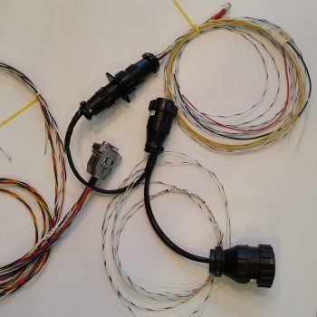
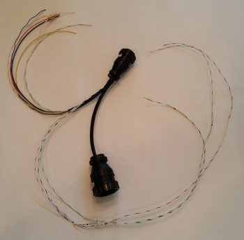
I then soldered two 22AWG wires close to the terminal pin on each of the actuator motor power wires on the P1-A connector for the gear up & down transit LED indicators.  After I soldered the wires in place I heat shrank the soldered joints to secure the wires & junction. I then finalized the A side of the P1 AMP CPC connector, covered the wires that traverse to the RCU’s P0 connector with a mesh cover, cut the remaining wires that will terminate into the P2 connector (upper left in pic below) to length and then snapped a shot of it all.

Along with the main nose gear wiring diagram, I also updated the P0, P1 and J9 connector pinout diagram pages.  Tomorrow I plan on working on the taxi light actuator extend & retract mechanism to get that knocked out.


Chapter 13/25 – New age art . . . ?

Or pinholes?  Ahh, it’s the latter my friends!

I have to admit when I first pulled these pics up on my phone I was wondering what the heck I had taken a picture of…

But, alas, since I sanded down through the actual epoxy wipes into the micro layer on each side of the cover in its never-ending contouring cycle, I created (or uncovered) some pin holes… which of course is the main things the epoxy wipes eliminate.

So, before doing some electrical diagram administrivia this morning, I did some quick epoxy wipes in a few targeted areas on the aft NG30 cover.  Like I had stated before, today will be a light build day, so this will be all I have to report.


Chapter 13/25 – Primed aft NG30 cover

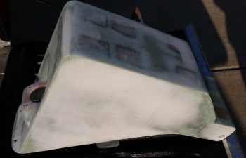
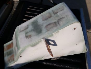
Although I didn’t get a lot done today I think it was fairly significant.  I started off by sanding the entire aft NG30 cover down in preparation for priming.  That was nearly an hour effort in and of itself.  It’s interesting how “straight” these components can look to the naked eye, but once you apply micro and sand it down, then even the subsequent sanding after a few coats of epoxy, you see how off it was from the beginning.  No worries of course because that’s exactly what the finishing process is all about.

After I sanded it, I washed it down with Simple Green and set it outside on my truck tailgate in the sun to dry thoroughly.

I then took the aft NG30 cover around to my side yard and hit it with 3 coats of primer.

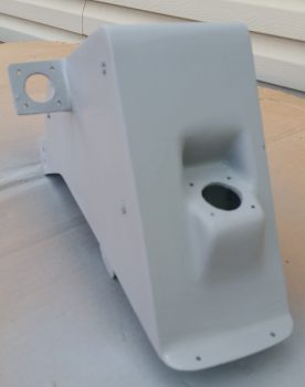
Here’s a couple more shots after I brought it back into the garage.

I then wet sanded the tool box lid with some 500 grit sandpaper.  It looked like all the imperfections were gone, so I cleaned it up, and printed out a label for it (which I mistakenly roughed up just barely with the 500 grit sandpaper).

Labels are notoriously difficult to clear coat, so I misted it a couple of times before hitting it with a full application of clear coat.

However, I think unlike the regular Rustoleum paint with its “few minutes” between coats, the clear coat has a quicker flash time in between coats (my current guess, but I’ll have to research more) because what started out as minor workable orange peeling turned into cracks that would put those in the Gobi Desert to shame!  In short, adding the label and clear coat Round 1 was a GIANT FAIL!

Ok, lessons learned and back to the drawing board . . .

Tomorrow I’ll try to epoxy wipe some pin holes on the aft NG30 cover before heading out to my EAA meeting.   But besides that, it will be a light build day since mid-afternoon on I’ll be hanging out with some friends.


Chapter 22 – Taxi light mini-actuator

I started off today by cleaning up my rather unorthodox layup for the area in-between the taxi light flanges.

I cleaned up the taxi light mini-actuator mounting flanges.

I then drilled and mounted the battery tray mounting flanges for bracket and screw for the mini-actuator.

I then drew up the outline for the rectangular lightening hole in the battery tray.  This lightening hole will also allow me to view the battery strap and manipulate its velcro tabs.

I then drilled holes in the corners of the battery tray rectangular lightening hole.

I pulled out the Fein saw and got prepared to cut . . .

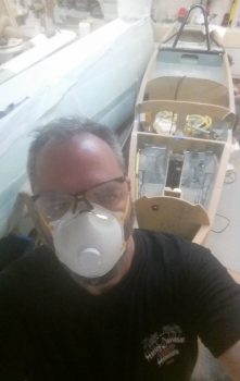
I then took a quick selfie to show the FAA that I’m the one actually building this bird!
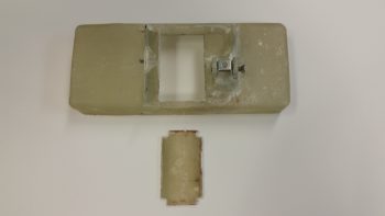
I then cut out the center rectangular lightening/viewing hole in the battery tray.

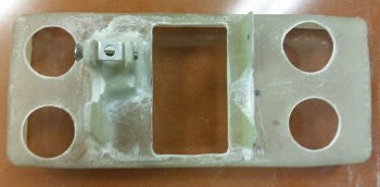
I then drilled 2 more 1″ lightening holes on each end of the battery tray.

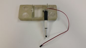
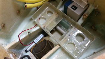
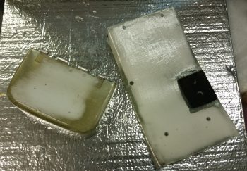
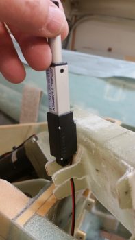
I then mounted the taxi light mini-actuator to the battery tray.  Out of curiosity I weighed the entire assembly pictured below and it came out to 2.9 oz.

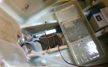
I then did a test fit with the whole setup in the nose battery compartment.

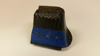
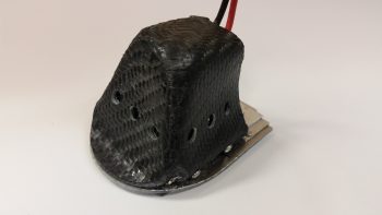
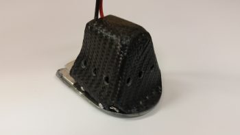
I had removed the taxi light cover to fill a couple of holes on the lower left side that I had mis-drilled for the mounting screws.  Before I remounted it, I sanded out a small rounded half-moon shaped indention on the top aft to provide clearance for the power wires.  I then decided, before remounting the taxi light cover, to go ahead and drill the vent holes on each side and the bottom/aft of the cover.

I then drilled 3 vent holes on each side.

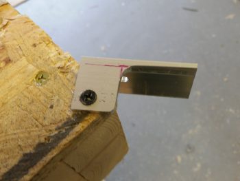
To test the initial actuator geometry that I figured out, I cut a test bracket out of a spare big piece of 6061 angle aluminum.

I don’t have any pics, but I messed around with the taxi light actuator and lever configuration for quite a while.  Unfortunately, I think my initial 1″ throw estimate for my mini-actuator is about 0.4″ too short.  Thus, I have to now start employing brain power –which I really was trying to avoid– to figure out how to implement some sort of mechanical trickery to turn the actuator throw from 1″ into 1.4″.  I have a few ideas, but tomorrow I’m going to spend my time finalizing the finishes on the NG30 covers and tool box and let my ideas germinate a bit.


Chap 13/25 – Paint starts now!
Ok, well, the paint starts in a bit.  Actually, the first thing I did today was cut out another battery tray lower flange out of G10 Garolite that will be paired up with the existing right flange –with a gap– to make up a composite U-channel for mounting the taxi light mini- actuator (pics later in this post show the configuration).

To add a little added strength for these actuator mount flanges, I added a foam spacer in the middle between them about 0.35″ high.  I micro’d the foam into place and then the new G10 mounting flange.

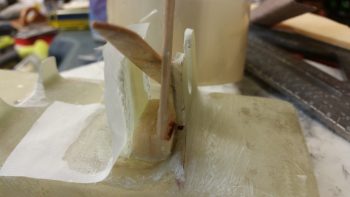
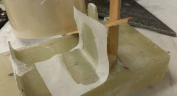
I then laid up 3 plies of BID on the inboard side of the new G10 mounting flange.  The popsicle sticks in the pics below are to keep the spacing correct between the 2 flanges, since the existing flange has just a bit of angle due to the glass configuration in the battery compartment’s lower channel.

I took another shot of the tool box lid and forward NG30 cover for posterity’s sake, just before I sanded them for primer coating.

I then sanded the tool box lid to prep it for primer.

And then did the same for the forward NG30 cover.

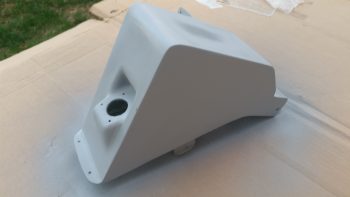
Here’s the tool box lid and forward NG30 cover in GRAY (although it almost looks white) primer.

I didn’t get a pic for posterity’s sake for the lower tool box body, so here it as after I primered it.

Again, although this looks white, the lower tool box body really is in gray primer here after a quick sand down and re-wash (I use Simple Green to wash my parts, a trick I learned when painting motorcycles).  This pic shows it right before I shot it with black paint

I then shot the tool box body black with 2 coats.

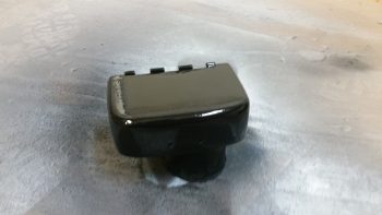
This is a couple of hours later than the pic above.  You can see the paint leveled out quite a bit as it cured, and it really does look good.  It’s not perfect, and if it were an external part or in constant view I would probably wet sand it and shoot it one more time, or clear coat it.  But this tool box is going into the nose, with the body mostly covered by the battery and the lid, so I’m going to call this good and press on.

I actually did the following while the tool box paint was curing.  I cleaned up the layup on the added inboard battery tray flange for mounting the taxi light mini-actuator.

Here’s a quick mockup shot showing how the taxi light mini-actuator will look in relation to the battery tray mounting flanges. [NOTE: To be clear, the battery tray is turned up on its aft side so that my fingers in this pic would be toward the front of the battery compartment].

If you aren’t confused, good!  But to show further what I’m talking about here’s a good representative shot showing pretty much how it will look when the mini-actuator is installed onto the battery tray mounting flanges (I actually took these 2 shots for Marco to explain to him what I was up to…].

For the NG30 covers, being much larger center pieces when the nose is opened up, I decided to clear coat them from the get go.  Still, nothing too fancy.  I grabbed some flat white Rustoleum primer and am using that for the base coat.  After the base coat cures, I’ll wet sand it and then I’ll hit it with a few rounds of clear.  Depending on how that turns out, I may do one final wet sanding and another coat or two of clear (sorry the pic quality, it seems my phone has been having issues focusing lately.  I think I’m going to have to switch back to the camera ….)

I had to do a fair amount of sanding after the first round of primer on the tool box lid, so I went ahead and re-primered it with another couple of coats.  After I good amount of time I picked it up in ham-fisted fashion to see how it looked, and disturbed the primer on the top side.  So, I hit it again with a good wet coat of primer on the top and let it cure some more.  After a bit of time went by, I threw it under a heat lamp for a couple of hours to get it nice and cured.  I then re-sanded it, gave it a Simple Green bath and then hit it with 3 coats of black.  FYI, this black is primer + gloss black paint mix.

I did do one more thing that I don’t have a pic of before I called it a night: I laid up 2 plies of glass in between the taxi light mini-actuator’s 2 mounting tabs on the battery tray.  I then peel plied the layup.  Tomorrow I’ll trim & clean up the layup, as well as prep the big daddy of them all for primer & then paint: the aft NG30 cover!