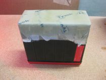
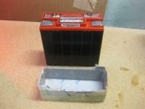
Chapter 13/25 – Finishing nose parts

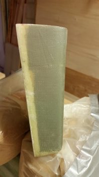
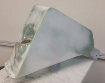
Today was a long build day overall, but not an overly productive one.  The reason being that today was essentially epoxy wipe day for the tool box . . .

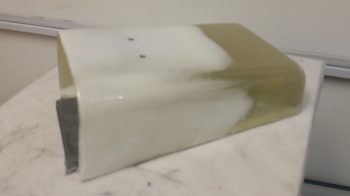
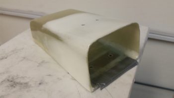
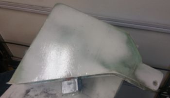
And the aft NG30 cover.

After prepping the parts late this morning, I applied the first epoxy wipe (using West) and then waited 2 – 2.5 hours and then added the next coat, waited and then repeated.  I applied a total of 4 coats of epoxy before letting them alone to cure overnight.

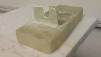
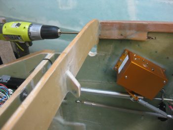
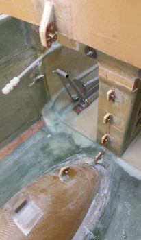
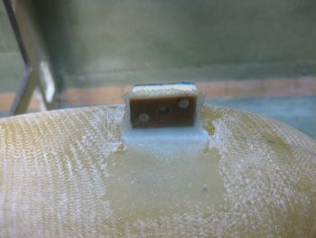
In other news, I cleaned up and shaped the right battery tray flange in preparation for adding a tab (smaller flange) just inboard of the right flange to allow me to mount the taxi light mini-actuator to the battery tray via these right side flanges.

With the aft NG30 cover and tool box body epoxy wipes curing, I checked them one last time and then called it a night.


Chapter 22 – Taxi light cover salvaging

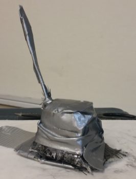
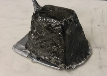
Today was the Big Reveal day for the taxi light cover.  Since my layup was practicing the truest form of accelerated entropy last night, I simply covered it with Saran wrap and taped it up profusely!  This morning I took off the long cross pieces of tape that I used to keep the whole layup from squeezing up the sides of the taped form, really making the cover unusable if it had.  I was now at the precipice of finding out what I had underneath of all this tape.  Would it be usable?  Would have I have to start all over again from square zero?Let’s find out . . .

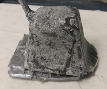
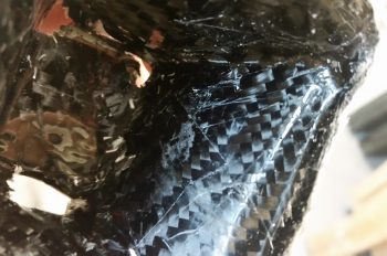
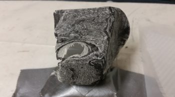
Ok, so here’s the result in Airdog’s crazy layup experiment emporium.  Quite an interesting specimen I’d say, but it really does look usable.  As I’ve mentioned many times before, so much of these one-off custom jobs are ITERATIVE processes!

I grabbed my sanding block and my Perm-A-Grit tools and went to town on the taxi light cover.  I knew that I would most likely create some holes in this cover to get the shape worked out correctly . . . and I was right.  It is interesting that the resulting pics all look quite a bit like snake skin.

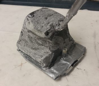
Here’s the opposite side.  It may be a bit difficult to see, but because I taped the top of the cover down, it resulted in 2 actions:  One negative, and one ok.  The negative action was that it created “shoulders” on each side of the cover just below the top.  My plan was to cut these off and layup a ply of BID that will bridge across the resulting hole.  The squashing of the top resulted in the 2nd action, which was that it pushed the sides just below the “shoulders” inboard more…. which was fine and actually allowed for a tighter fitting cover (i.e. takes up less room).

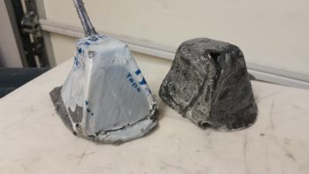
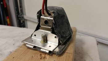
Here’s the sanded taxi light cover next to the taped up taxi light that I used as the cover form.

Also, here’s a shot of the inside of the taxi light cover.  Aside from scratches from the scribe I used to pry the cover off, the carbon fiber really looks nice.  Overall, this pic again has a snakeskin look to it (Marco also pointed this out when he saw it).

After assessing the cover’s usability –including cover mounting & removal– I decided that because the lips on each side clamp around the flanged base of the taxi light bulb mounting assembly, that I it was not practical to keep the forward side of the cover in place.  I cut off the forward face of the cover to simply allow the cover to be slid on from the bottom (if it’s deployed/out) or aft (retracted) side of the taxi light.  After testing this configuration I could tell immediately that I had made the right call on removing the forward cover side.  Much easier!

I then prepped it for more glass (repair layup, if you will . . .) by sanding it to shape.  This prep also included using the Fein Saw to remove the right “shoulder” just below the cover top, which left a decent-sized hole in the cover.

To keep this story line flowing, I’m jumping ahead here with my pics.  The pic below is exactly what I did above, but on the cover’s left side.  The yellow epoxy spreader is being employed as a form weight to keep the overhanging glass flat against the side lip.  Besides wrapping around the taxi light bulb mounting base to keep the cover securely in place, this side lip will get drilled in 2 places, and be held in place with two 4-40 screws.

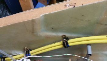
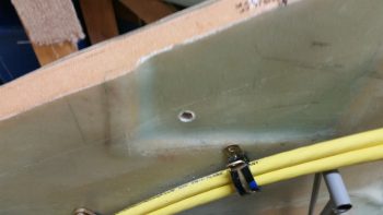
In addition to the taxi light cover, I continued to work on securing the 2 big power cables (one + power and the other – ground) that start in the nose battery compartment and end at the firewall & starter, respectively.  Again, I had to reroute these cables up and over my rudder pedal (you can see in the pic how they get in the way if not wrangled) in an arch/ Bell curve fashion.  With the 1st added Adel clamp in place, I marked the position for the 2nd additional Adel clamp.  Note in the upper right hand corner of the pic my markings for the Atkinson pitch trim actuator mounting.  You can see that I need to get these power cables as high up on the nose sidewall as possible, but still remain clear of the pitch trim actuator mounting.

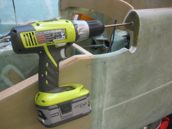
After marking the spot, I then drilled the hole in the nose sidewall.  This area was a bit tougher to drill since, if you recall, that indented area that this hole was placed has additional plies of BID to beef it up for the mounting of the pitch trim actuator.

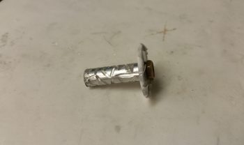
I then performed the “poor man’s” knurling of the 10-32 threaded aluminum insert that will be used to mount the Adel clamp in this location.  I wanted to use this threaded insert since it’s a bit more robust than a RivNut.

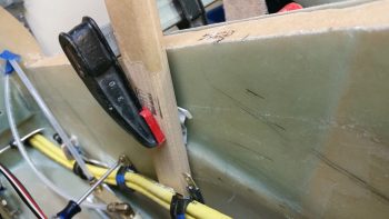
I then whipped up some flox and mounted the threaded insert assembly (including a taped washer mounted to it with an AN3 bolt).  I then clamped it in place to ensure it would be level with the surrounding sidewall surface when it cured.

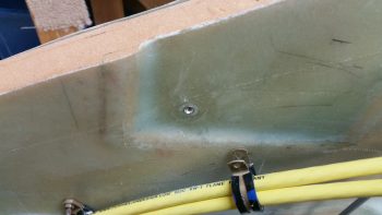
Here’s a shot about 10 hours later after it cured to about 80-90%.  The flox was still just barely soft enough to be easily removed with a razor blade (there was an entire ring of it around the perimeter of the taped washer).

Although it’s a bit slow going, I am getting through all the electrical related taskers on my list.  I expect about another week, maybe 2 at the most, before I’m ready to get back to the big chapter build items again.


Chapter 22 & 25 – Done, Done & Done!

Today I got a few things checked off the list.

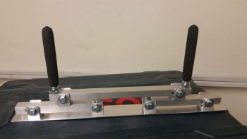
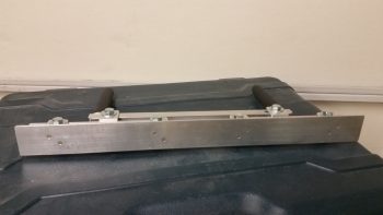
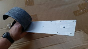
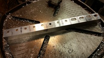
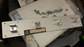
First, I finished constructing a micro spreader to hopefully accelerate the finishing of the aircraft surface in prep for painting when the time comes.

Here’s a shot of the actual bottom plate working surface.  You can see I used 2 counter sunk aluminum rivets per bracket to hold the bottom spreader plate to the 4 individual brackets.  I figured 2 rivets per bracket would be enough since the primary force on the spreader plate is from the top as it pushes the micro over the aircraft skin.  If there is any issue I can of course beef up the bracket attach points.

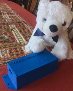
Next, I got this pic from Marco showing my finished Nose Gear AEM box and a United Airlines bear he picked up for my little 7 year old buddy (a friend’s daughter) who loves flying.

Finally, the box Marco 3D printed for me for the Nose Gear RCU had a slight blemish on the lid, so I’ll hope he’ll forgive me for me filling it in a bit and painting the lid black.  Here’s the finished Nose Gear RCU box ready for mounting into the aircraft.  I will of course have to terminate the wires on the “B” side of the connector.

With my bridge sander, micro spreader and RCU box distraction projects out of the way, I can now get back to my list of electrical system related taskers that need to get knocked out.


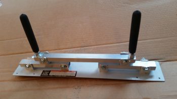
Chapter 25 – Self-rolled Bridge Sander

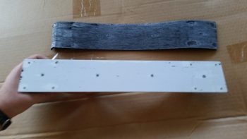
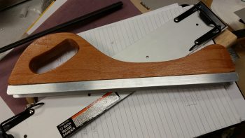
I took a bit of break from my normal build actions to do a quick tool building project. Starting yesterday & finishing today I’ve been working on constructing a bridge sander as Nick Ugolini spells out how to do on his blog.  Once again, I was notified of this brilliant contraption by the watchdog of the canard world, my friend Dave Berenholtz who is blazing through his Long-EZ build down in OZ (check out his blog here).  Coincidentally, Mike Beasley also built one of these as he was finishing up the major sanding of his Long-EZ as well.

For the base, Nick calls for using 1/16″ thick x 1-1/2″ wide aluminum that you can easily buy from Lowe’s, Home Depot, etc.  I did pick up some of that aluminum for the micro spreader, but for the sander it just wasn’t wide enough for me so I picked up a cheap automotive rigid sander at Harbor Freight after assessing that the aluminum base looked as if it would be amenable to getting pressed into service as a flexible sanding board.  As for parts, one other point of note: Nick calls out for 1″ square tubing to be turned into 6 U-channel pieces and then a separate piece of 7/8″ U-channel to be used inside the 1″ share tubing/U-channel above.  Well, I found the 1″ square tubing, but not the 7/8″ U-channel so I ended up using some 1″ wide U-channel I had on hand with 1/8″ walls, then buying 3/4″ U-channel to go inside that.  Just a slight variation that worked out really well.

I started off by ensuring that I could dismantle the Harbor Freight sander to ensure I wouldn’t destroy it in the process.  I peeled the rubber pad off the bottom of the base to gain access to its 4 handle mounting screws.

I simply used my fingers to pry off the bottom rubber pad, with an occasionally use of my utility knife to round up any errant pieces of rubber that decided to stay on the aluminum rather than come with the rubber pad.

With the sander broken down into an acceptable number of pieces, I then did a final assessment on whether the aluminum base would be flexible enough to be used in this type of sander.

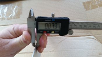
Since the base off the HF sander is only 0.01″ thicker than the 0.063″ (1/16″) called out for by Nick, it looked as if my eevil plan was going to work!

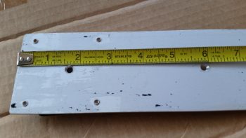
An added bonus in using the HF sander was that the screw holes in the base for holding on the wood handle are at the perfect dimensions that Nick calls for on his blog: approx. 1-1/2″ and 6″, respectively, from each end.  Pretty cool.

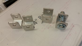
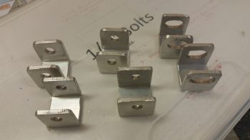
I cut enough of the brackets and aluminum pieces for two of these things since I’ll also be building the micro spreader, but I wanted to get the sander under my belt first.  I marked up the U-channel for 12 each 0.9″ wide brackets, 6 for the sander and 6 for the micro spreader.  Of the 6 brackets for each, 4 will get normal holes drilled through them while 2 will require slots.  Since I’m using cheaper Zinc bolts, 1/4″ is the smallest diameter I could get (versus the 3/16″ AN3 hardware Nick used).

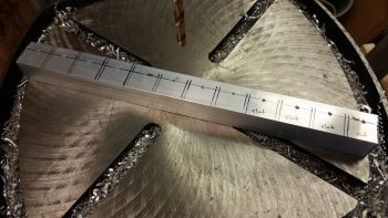
For easier drilling of the holes and the slots, I drilled them all before I cut the U-channel into the respective brackets.  Yes, since I don’t have a mill my slots are pretty sloppy, but for this purpose I’m sure they’ll work fine.

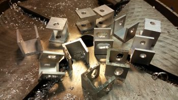
I then cut 12 brackets from the U-channel

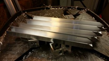
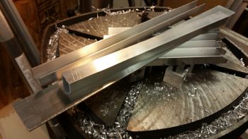
And then cut the 3/4″ U-channel into the approximate lengths for the first layer of cross supports.

Finally, I cut the 1/16″ x 1-1/2″ aluminum for the micro spreader to 16-1/2″ long.  I also cut 2 longer lengths of the 3/4″ U-channel stock for the top cross supports/handle bases.

I drilled the 4 holes through the U-channel for my bridge sander and mounted the handle base.

And then started the arduous process of cleaning up each bracket.

I cleaned up 4 straight-holed brackets and 2 slot brackets for the bridge sander, and left the 6 brackets for the micro spreader for later.

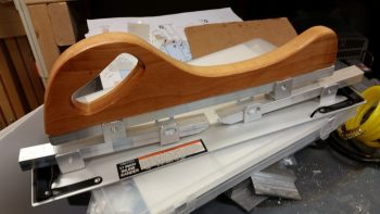
I then mocked it all up to see how it would look.  Not bad!

I then drilled a hole in each of the bottom brackets that attach to the base for mounting.  I drilled them just a bit off-center to allow for mounting one countersunk rivet through the base into each bracket to keep the alignment straight.  This was the last action of the evening since I wanted to ponder on the handle a bit.

I called it a night, but I couldn’t help but get the feeling that I needed to go with the “traditional” 2-handled setup vs. using the HF sander’s wooden handle.   So this morning I used the handle base/cross support 3/4″ U-channel stock that I had cut for the micro spreader and drilled the final holes into it to allow it to be bolted to the two sander cross supports, and also add two 3/8″ bolts for handles.  I cut about an inch off the top of each handle bolt to allow me to use rubber slip-on grips from McMaster-Carr.

It looked good, but my quick testing of it proved to me that it’s the downward force against the surface being sanded that determines the conformal action of the sanding base, not the actual configuration of the handles.  So my initial hunch was right, and thus I’ll drill up the the base with the wooden handle to see how that works.

I have out-of-town company so the build will be a bit slow over the next few days, but I am happy that I got this reportedly invaluable finishing tool constructed.


Chapter 22 – March Madness Brackets!

Well, My March Madness brackets!

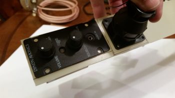
Today I started working on the brackets for both the P4 throttle connector bracket and the Intercom bracket.  As for the Intercom bracket, I decided that I’ll most likely make the right pilot armrest removable to gain access to intercom wiring.  So the intercom mounted in the bracket will remain on the sidewall, allowing the armrest to be pulled away from it.

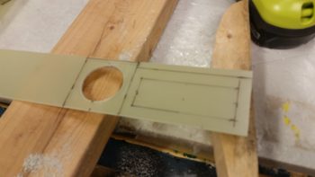
I started off by determining the dimensions of each bracket, and then marked up a 1/16″ piece of G10 with these dimensions.  I then drilled the 1.5″ hole for the Throttle P4 AMP CPC connector.

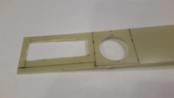
I then cut the rectangular hole for Dynon Intercom.

And then test fitted both the Intercom and the P4 connector, with both fitting just fine.

After prepping the holes I took the evening off to go to dinner.

Chapter 22 – Lightening the Load!

I started the day off by finalizing and pulling the trigger on both a Mouser order and a quick ACS order (it appears that someone –ha!– forgot to order some 22 AWG shielded wire…).

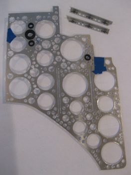
I then got to work on the Triparagon vertical plate.  I stripped off the cross plate, diagonal support struts and the Schottky diode/heat sink and got to work for the last and final serious round of lightening holes.  The starting weigh-in this round for the Triparagon vertical plate, with the grommets and cross shelf brackets including 6 x K1000-3 nutplates, was 0.82 lbs.  My goal was to get the weight down by another 0.2 lbs.

After drilling a 1″ lightening hole and 10 each 5/8″ holes, it weighed in at 0.78 lbs.  At this point it was really time to get work.  As you can see, I Swiss cheesed this thing like no tomorrow to drive the weight down to its possible lowest, without sacrificing strength.  I used an 11/32″  (0.344″) drill bit to get all the in-between spots that I could while, again, still leaving enough meat on the bone for this thing to be as strong as it was before.  It is an interesting concept that you can remove so much material, but when I flex it, it feels as strong as when it was a solid panel.

Making Swiss Cheese!

After squeezing in as many 11/32″ holes as I could (I have about 3-4 more places I can get with a slightly smaller bit), and drilling 3/16″ lightening holes on the upper arms of the cross shelf mounting brackets, I’m sitting at 0.68 lbs. for these components.  Obviously, this isn’t quite as low as my 0.62 pound mark, but I’ve squeezed just about all the weight out of this thing that I reasonably can.

When I weighed the entire Triparagon assembly as a whole, it weighed in at 1.18 lbs, including hardware.  Since I have just a handful of lightening holes to drill, if I add in the weight of the aircraft-side mounting tabs and the hardware, I’m right around, or just a hair over, 1.2 lbs.  My initial goal was a pound or less for the entire Triparagon’s added total weight, so an extra 3.2 ounces ain’t bad… I can definitely live with that.

Thus, as Vince Lombardi said, “Perfection is not attainable, but if we chase perfection we can catch excellence.”  Clearly I didn’t reach my ‘perfect’ requirement, but I got pretty close.  In putting in a lot of effort to get as much weight off these components as possible, I feel like I’ve definitely achieved excellence in that regard.

Tomorrow I’ll spend a few hours chamfering the myriad of lightening holes I drilled today. I’ll then rivet the cross shelf mounting brackets in place, drill lightening holes in between the rivet locations and call the Triparagon build complete!


Chapter 22 – Electric Push

I started off today with the intent to finish the edging on the lightening holes on the Triparagon cross shelf.  But that didn’t happen.

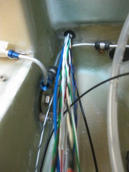
What did happen was I did a test fit of the IBBS & it’s ‘new & improved’ wiring harness.  Part of that test fit was to ensure that ALL the wires –not just the IBBS wires– fit through the hole & protective grommet that traverses the Napster bulkhead.  And, as per usual, since I just happened to be in the neighbor hood, I figured I couldn’t really test if the wires fit unless the actual wires (and cables) that will run through this transit hole are used in the test.

So I decided to go ahead and get the landing landing light and taxi light wiring/cabling knocked out.

First up was the landing light.  The installation manual for the AeroLEDs Sunray Plus landing light calls for using 20 AWG shielded wiring to power the light.  I only had 22 AWG on hand, so I used it since I’m confident that it will work since the actual run is only about 5 ft vs 3-5 longer than that if it was buried out at the end of a wing somewhere in a “typical” install.

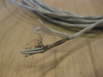
I started by stripping away about 2″ of the outer jacket.

2-wire 22AWG shielded landing light cable

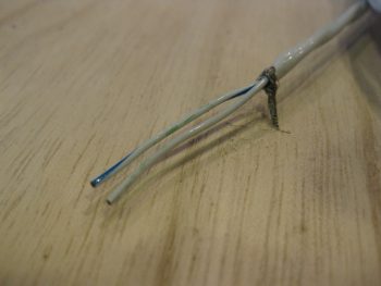
I then wrangled and cut the shielding wire.

Wrangling shielding on landing light cable

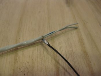
And soldered a piece of 22AWG black wire for the ground wire.

Ground wire soldered to shielding on landing light cable

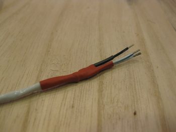
I then heat shrinked it all up: red to symbolize positive power, and black for the negative ground wire.

Landing light cable end reinforced with heat shrink

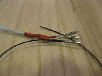
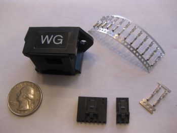
I then terminated the wire ends with mini-Molex socket connectors.  Note that the black pigtail wire will actually terminated on a mini ground tabs block that I’ll have mounted onto the negative post of the battery.  [Note: Although I’m not a fan of Molex connectors for the larger, multi-pinned connectors, the mini-Molex connectors work just fine for 2-6 wire applications … just my opinion, YMMV].

Landing light cable min-Molex sockets & ground pigtail

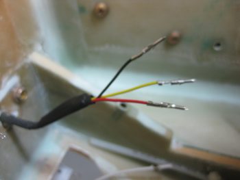
I then prepped the landing light side.  I had 2 extra wires that I simply folded back onto the main cable and heat shrinked in place.  I then terminated the remaining 3 active wires (red for light power, black for ground, yellow for wig-wag) with mini-Molex pin connectors.

Fuzzy land light wires prepped & pins crimped on

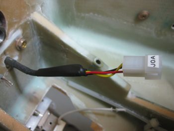
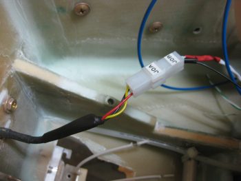
And then attached the 4-pin mini-Molex connector (J0, A side).

mini-Molex connector (J0A) housing in place

After running the landing light cable through the hole & grommet in Napster, I then connected the J0B side of the landing light connector to the J0A side.  Looking good!  Note in the pic above and below the white wire leads of the taxi light, those will change in a bit.

Landing light cable connected to landing light

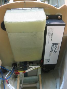
I had previously installed the IBBS to test its fit.  As a side note, after some investigation I realized that the end of the IBBS box cover (that has the “IB” label attached) was bowed out a bit & thus not allowing me to use normal sized AN3 nuts.  So I removed the IBBS cover, gently pressed the end back straight, reattached it and . . . Voila!  It mounts perfectly!

Back to the wiring… Get this: to get all the wires to fit, I actually have to removed the grommet out of the lower wire transit hole in Napster, then push the 2 knife splices through, then the PIDG FastOn connectors for the IBSS power & ground wires, then reinsert the grommet before the rest of the wires can go through.  Also, I can’t terminate OR LABEL any more wires at this time if they are going to fit through that hole…. VERY TIGHT FIT! Which is good because of course it keeps the wires secure.  It also gave me a chance to try out my “Wire Spoon” that I picked up from Stein a million years ago and have never used.  Works great and really does allow you to insert wires through the hole in the midst of a big wire bundle that you would otherwise not be able to get in there.

IBBS test install & wire run to ensure fit/clearances

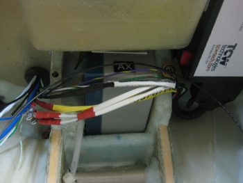
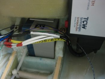
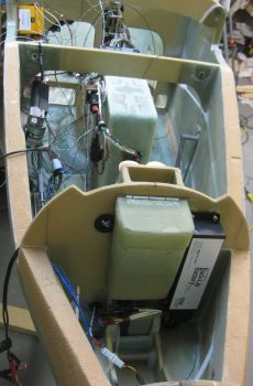
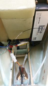
The next couple of shots are simply closeups of the IBBS wiring harness crossing over the nose gear back up battery, just underneath the nose tool box, and exiting out of the nose through the lower hole in Napster.  (You get a better shot of the IBBS harness “U-Turn” in pic #2).

IBBS wiring harness in & test fit wires thru BH

IBBS test install & wire run to ensure fit/clearances

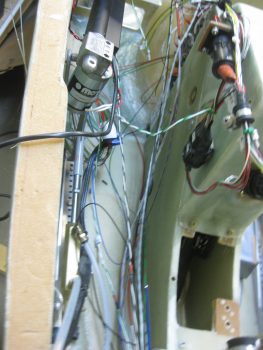
Here’s a long view of “Electron Alley” showing the myriad of wires that are currently in play and that I’m contending with.

"Electron Alley" - lots of wires!

I then set to work to terminate and wire up the Taxi Light with a 22 AWG blue wire for power (blue just happens to be the color of the wires used in the Infinity stick grip for that switch, so I carried that color all the way through) and a 22 AWG black wire for ground.  Note that I also labeled the wires on the light side, something I didn’t have space to do on the landing light.  I finished off the installation using a 2-pin mini-Molex connector (J7) that I bought well over a year ago specifically for the taxi light connection.

Taxi Light connector & wiring

Here’s a closer shot of ‘Electron Alley’ . . .

"Electron Alley" - lots of wires!

And a shot of the lower wire transit hole in Napster from the aft side.  The wires you see are currently all the wires that I plan on having transit through this hole (yes, things can change, thus the emphasis on the word “currently”!).

Aft side Napster BH wires thru hole and grommet

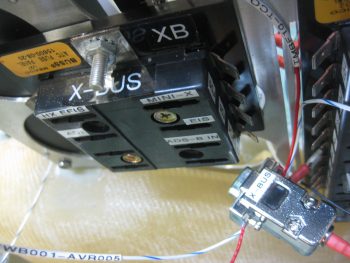
I also wanted to get a pic of the old ATC fuse block X-Bus (left) compared to the new 9-Pin  D-Sub X-Bus (right).  As I pointed out before, this modification will save space, weight and complexity (e.g. no individual fuses).

Old vs New X-Bus

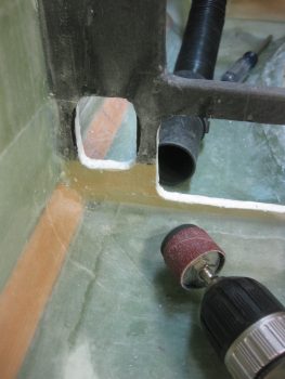
I was heading out to dinner with a buddy of mine, but before I ran out I wanted to get one more thing finished for the evening: widen the lower left hole in the instrument panel bulkhead to allow the P4 connector, which was just a tad too big (note the black markings on the sides of the hole) to fit.  I used a sanding drum on my drilled, fired up my shop vac and went to work.

Widening lower left hole in IP BH for P4 clearance

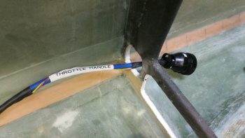
Less than a minute later . . . Voila!  Now the P4 connector just fits through the hole!  My next step will be to add an Adel clamp to keep the throttle handle cable secure.  I would like to reiterate my ongoing theme here by pointing out that this is the type of stuff I really want to get figured out before I close up the nose, while I have infinitely much more access to work on it all.

P4 connector access thru IP bulkhead

Tomorrow I’ll continue on with my push to knock out the avionics area electrical stuff, as well as get the Triparagon install finished. (Then, on to the wheel pants!)


Chapter 22 – Warning!

After spending a good bit of time in the AG6 warning annunciator manual last night, I started off today once again with about 1-1/2 hours of updating my initial electrical diagram for the dual AG6s I have installed.  I had originally only had the AG6s on this diagram with all other warning circuits listed in diagram 16, which specifically has a small housed module for the gear & canopy warning annunciation (shown below) along with the other warning stuff.

However, since I pulled all the individual warning LEDs off my panel and routed them all through my AG6s (the exact reason why I bought another one) it stands to reason that to show those circuits ALL warning circuits other than the gear & canopy warning module needed to be on the AG6 wiring diagram page while only the gear & canopy warning module wiring is depicted now on diagram 16.

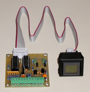
I also realized after looking to copy a pic of the AG6 annunciator to show in this post that I may have never actually posted a pic of one.  These are stock pics below from the company who makes them, Aircraft Extras, Inc.

Here’s the entire system, with the boards mounted back-to-back on the upper Triparagon. Each board will have 6 warning circuits for a total of 12 and will display on a button that can be pushed in to acknowledge an alarm state.  Of course 2 AG6s means 2 display buttons on my panel.

AG6 Annunciator System

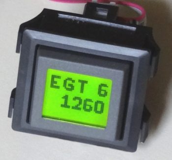
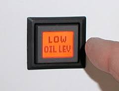
There are 3 available background colors for the AG6 display screens: red, green and yellow.  Below is a couple representative pics of the red & green displays.

AG6 Annunciator display buttonAG6 Annunciator display button

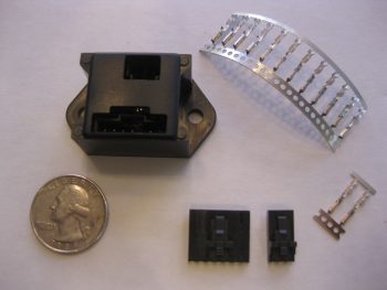
I also couldn’t find a shot of the JBWilco gear & canopy warning module that I’m using in my system.  I picked this up from a guy who built a bunch of them after he designed it for use in his Cozy.  He got tired of making & selling them, and I just happened to contact him right as he was selling his very last one.

J.B. Wilco Gear & Canopy warning module

As you can see, this module is very small and very light.  This will actually drive a pair of red & green LEDs on my panel.  These will be the only LED warning lights on my panel, since I’m wiring the Wilhelmson gear & landing brake LED pairs up to the AG6s to display gear up/down and landing brake up/down.  This module will sound a warning for the gear & the canopy, both visually through the LEDs and also through a warning buzzer.  BTW, this gear & canopy module will be the only warning that uses a buzzer.  I may configure other warnings to provide audio warning tones, but those will all be driven through the EFIS and only be heard via headphones.

J.B. Wilco Gear & Canopy warning module

Down in the shop I cleaned up the aft lower Triparagon mounting tab. I didn’t like the way the lower glass was attached on this tab from my original 2-ply BID layups on the right side of the nutplate mounting hard points, so I ripped off the glass and sanded it down to remove the stubborn stuff.

I also took the time to clean up the other tab layups, ensuring the edges were sanded down smooth.  I also drilled out the remaining holes in the glass for the mounting bolts.  All this sanding, trimming and drilling made a bit of a mess….

Aft lower Triparagon mounting tab

So before I vacuumed it all up, I decided I would make just a bit more of a mess by using my long 1/4″ drill bit to expand the #10 holes in the longeron doublers + the new extensions.  The 1/4″ hole is for the 4130 sleeves that will provide a solid channel for the long AN3-62A bolts that I will employ on the top canard alignment tabs vs. the plans alignment pins.  This is a mod I had seen in passing before, but I really took note of it after checking out what my buddy Dave Berenholtz was doing on his upper canard alignment tabs.

I drilled the left side first.

Exapanding longeron doubler holes to 1/4"

Exapanding longeron doubler holes to 1/4"

And then the right . . .

Exapanding longeron doubler holes to 1/4"

After my short 5-min drilling task detour, I then vacuumed up the mess I had made in the avionics bay area.  I then grabbed a small piece of plastic and prepregged 2 plies of BID and laid up the aft lower Triparagon mounting tab.  As you can see, and not surprisingly, I then peel plied the layup.  What you don’t see is that I then lightly clamped the same block of tape-covered wood that I used before to compress the glass a bit.  Finally, I used the leftover epoxy to seal the exposed bare foam on the 3 edges of each Triparagon nutplate mounting point.

Triparagon mounting tabs

With the lower mounting tab BID curing, I then took the Triparagon upstairs to finalize the on-board wiring cross-connects.  I started by printing out a number of wire labels on the white shrink tubing.  I then terminated two 22AWG red wires into one FastOn tab, one leg each to power the respective AG6s.  This FastOn connector will be mounted above the 2 shown on the left side of the E-Bus in the very left of the pic below (using the installed 1A fuse).

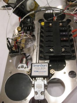
I then spent well over an hour finalizing the wiring for the Trio autopilot’s Autotrim feature. For the autotrim to work it must interface correctly with the TCW Safety Trim box.  While I was over in Qatar I worked with the respective gurus, Chuck at Trio & Bob at TCW, to finalize the circuitry for the autotrim.  With both of the gurus in coordinated agreement on the wiring scheme 2 years ago, I am just now finally able to implement it.  If you look along the upper left edge in the pic below (which is the actual upper forward edge of Triparagon), starting from the bottom you’ll note the DB15 connector housing from the Safety Trim box mounted on the other side of the Triparagon, then a Bridge Rectifier, then a relay marked “RP”.  These components make up the Triparagon side of the Autotrim system.  Once these interfaces are combined with 2 wires coming from the AP pitch servo and 2 wires coming from the Atkinson pitch trim servo motor, then Voila! … the Trio AP autotrim feature is wired for operations!

Trio A/P Autotrim & TCW Safety Trim interconnects

Being the social butterfly that I am, I then took the rest of the night off and went to dinner & a movie.  When I returned, I pulled the peel ply and checked the 2-ply BID layup on the aft Triparagon mounting tab.  Looks good!

Reglassed aft Triparagon mount tab 2-ply BID

Tomorrow I’ll clean up the overhanging glass and excess flox with my Fein saw.  I’ll of course redrill the bolt access hole, at which point I should be finished with my Triparagon nutplate mounting hard point installation.


Chapter 12 – Canard Mount Prep

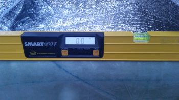
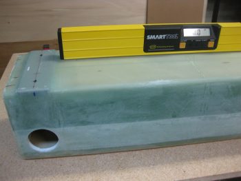
Before I started sinking my teeth into prepping for the canard installation on the fuselage, I wanted to check how the fuselage longeron angles were looking.  Since there’s been some fairly significant swings in temps with the weather over the past couple days, I was curious to see if it had affected the front tire at all.  It didn’t and the fuselage is still locked at 0°.

Rechecking longeron levelAfter re-reading Chapter 12 in the plans on the canard installation, I then got to work on prepping as much as I could get in tonight for the upcoming canard install.

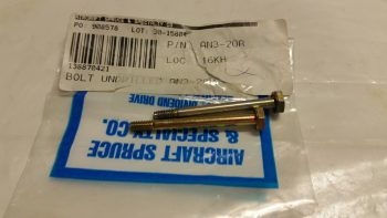
I started by rounding up my two AN3-20A bolts that will be modified to be used as the top canard tabs alignment pins.

Canard top AN3 alignment pins

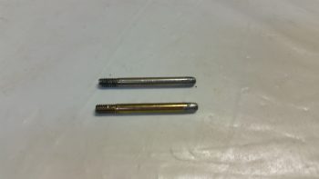
I cut the heads off the bolts and then rounded them over some.  I’m not getting too particular here since I don’t plan on actually using these as alignment pins.  Instead, I’ll be going the route of a fair number of other builders who drill a hole all the way through the longeron doublers and then install a long AN3 bolt with a nutplate to secure the top tabs of the canard.  Reportedly, this makes installation & removal of the canard much easier, and I’m all about making things easier.

Canard top AN3 alignment pins

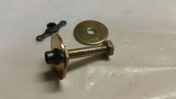
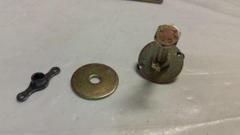
After finishing the alignment pins, I then started working on the nutplates that will be used to retain the main canard mounting bolts on the bottom mounting tabs.  Interestingly, Chapter 12 doesn’t describe any of the steps for making these nutplate assemblies, but instead merely refers the builder to the diagram on Page A7.  On A7 it shows a K1000-4 nutplate riveted to a AN970-4 washer.  The rivets actually appear to be drawn as Cherry pop rivets, but flush rivets are called for by part number.

To keep the nutplate centered on the washer, I used an AN4 bolt with a regular nut on the side opposite the nutplate.

Making canard mount nutplates

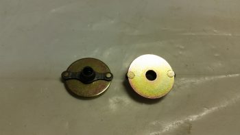
I then drilled the holes using the nutplate as a guide.  You can see that these holes are very close to the edge, but I doubt it really matters much since compression will keep the nutplate tight against the washer.  Let alone the fact that this all gets permanently mounted  to the aft side of F22 under a ply of BID.

Making canard mount nutplates

And here’s the final product.

Canard mount nutplates

Tomorrow it looks to have a good chance of being rainy during the first half of the day, so I’ll focus on prep work.  Then I’ll move into working on mounting the canard in the early afternoon.


Chapter 14/19 – Begin Wing Mounting

Today was a heavy prep & work day, both in regards to mounting the wings to the CS spar and in finishing up my miscellaneous tasks from yesterday . . . so let’s get to it!

Of course the battery tray was nice & cured this morning…
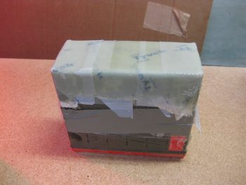
Battery tray cured

So I pulled off the peel ply, then the protective tape on the battery itself.  I then worked the battery tray off the battery.

After I got the battery tray removed (and yes, it’s a tight fit!), I then pulled the tape from inside the battery tray.
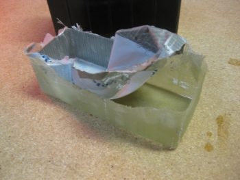
Battery tray tape removal

The result was nice in that there was no SNAFUs!
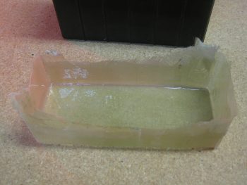
Battery tray ready to trim

I then quickly set the battery back in the tray to test out the fit… nice & snug!
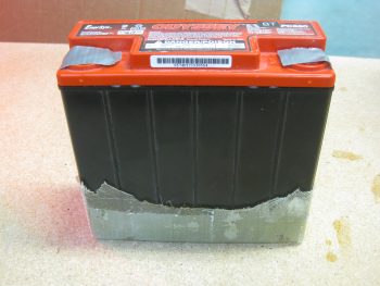
Battery tray test fit: Good!

In my expert opinion (ha!) I’d say the tray looks a bit rough, so I marked it up for some trimming.
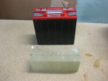
Battery tray marked for cutting

I also marked the tool box for trimming as well.
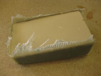
Tool box ready for trimming

I then grabbed my Fein saw, the battery tray and the tool box and took them all outside for a trim.  Here’s the result:
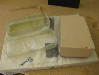
Battery tray & tool box trimmed

I’m really happy with the way the battery tray turned out.
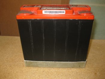
Battery tray ready for install!

I then got to work to lay up the aft wall of the tool box with 3 plies of BID.  Since I want a square corner on the back side of the tool box (where it hangs on the Napster bulkhead), I need flox corners (actually, I’ll be using Flocro… heavy on the micro).  So I marked & cut those out.
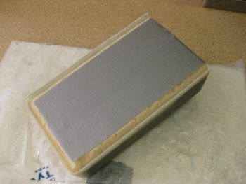
Prepping aft tool box

I whipped up some epoxy and some Flocro, with about 70% micro to 30% flox and filled in the wedged Flocro corner troughs.  Also, as you can see in the pic below just above the tool box (light green rectangles), I cut up 2 sets of 2-ply BID and pre-pregged them to lay up over the IBBS Clickbonds.
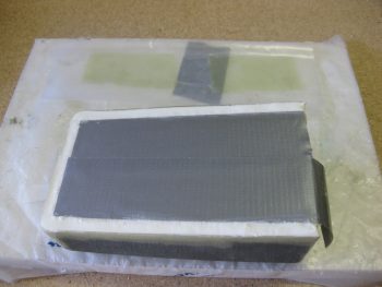
Flocro corners & IBBS BID top

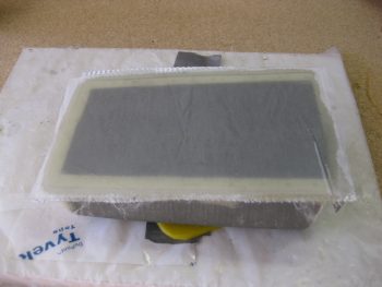
I laid up the 3 plies of BID on the aft wall of the tool box and then peel plied it.
Aft wall tool box 3-ply BID

As for the IBBS Clickbonds, below are some shots of the IBBS being removed from the floxed-in Clickbonds.
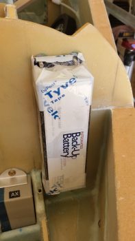
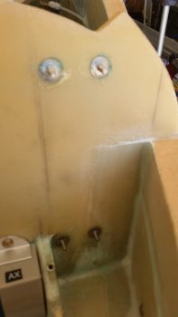
IBBS Clickbonds floxed in placeIBBS Clickbonds floxed in place

I then sanded all around the Clickbonds and cleaned them up to ready them for the 2-ply BID layup.
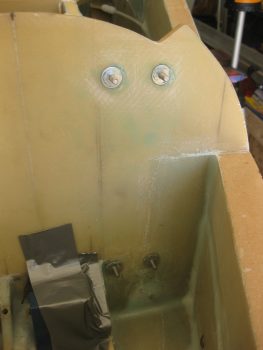
IBBS Clickbonds sanded

Here’s the BID layup that extends about 1″ from each Clickbond stud.  I also peel plied the glass to give a good transition.  To make it “form fitting” for the IBBS unit, I put the pre-preg plastic back in place.
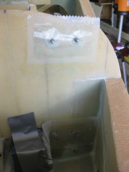
IBBS Clickbonds with 2-ply BID

I then reset the IBBS unit and clamped it back in place like I had it last night.  This will ensure that the BID immediately around the Clickbond posts lays down nice, flat & tight.
Remount IBBS for press fit Clickbonds

I took a break and ran up to Home Depot & to grab lunch.  I wanted a better jug to use for the water level system (the old one is on the bottom in pics below) so I grabbed a plastic jug of Simple Green.  I then poured the Simple Green into the old water container that I had considered using for the water level [it’s too big & heavy].
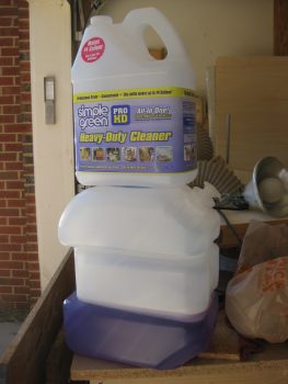
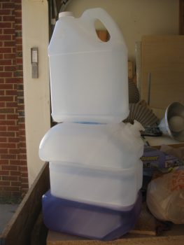
Simple Green jug for water level

Simple Green jug for water level

After getting the water level jug squared away, I then mixed up a few packets of Kool-Aid to use as coloring [Tip: Kool-Aid is WAY cheaper than food coloring!].
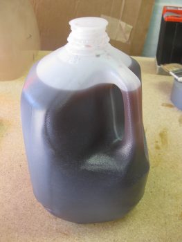
Kool-Aid for Water Level

After getting a bunch of the preliminary prep work out of the way, it was time to finally break out the wings from their multi-year bondage in my work shop!
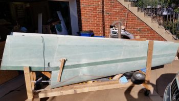
Removing wings from shop!

Although I actually took this pic a bit later, I wanted to post it here so you can get a good visual as to what I was doing.
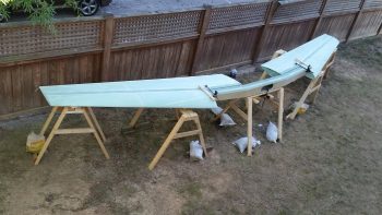
Wings & CS spar set up

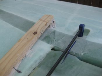
I started by clamping the ring wing to the CS spar to check the “A” & “B” lines as it states in the plans to do (“Waiter” really emphasizes this step as well).  I have to say that the marks are very close between the wings & CS spar, but there is a bit of tweaking that I’ll do –on the order of 0.04″ to 0.07″– to better hit center mass of the extrusions while drilling.
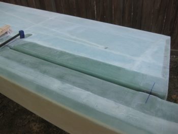
Aligning CS spar & right wing

Here’s a shot of my right outboard alignment… not too bad.
Aligning CS spar & right wing

And another shot to show the alignment.
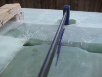
Aligning CS spar & right wing

Here’s a shot of the alignment on the left wing.
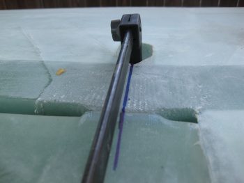
Aligning CS spar & leftt wing

And the inboard bolt extrusion area on the left wing.
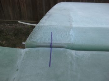
Aligning CS spar & left wing

I wanted to take this pic not as much for showing the antenna wires from the wings, but the fact that by using that conduit that I installed between the outer & inner CS spar bulkheads, I was able to slide each antenna cable into the CS spar in about 5-10 seconds. Very EZ!
Wing antenna cables

Back in the shop, and since I had my Fein saw ready, I chose to start to finalize another thing on my bucket list: the CS109 control stick tab.  The problem with this tab simply has its roots in the fact that I bought the control system from the Cozy Girls.  This isn’t to say anything bad about their components, because they’re awesome.  The problem is that their stick mount straddles the round control stick tube while the old control stick setup sits on the inboard side of it, or shall I say 3/4″ inboard of the Cozy Girrrls stick setup.
Removing CS109 for redo

My buddy & fellow EZ builder Dave Berenholtz points this out on his blog.  I took heed after a discussion with him, and will be remounting a new one further inboard which will provide a bit more clearance for the Cozy Girrrls’ control stick between the stick and the immovable fuselage side wall.  Since the back seat area was a bit cluttered, I’ll get to CS118 later.  For now though I know it will be a 3 minute job to remove CS118.
Removing CS109 for redo

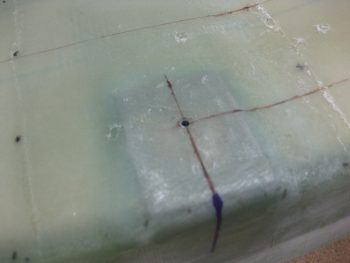
I then set about drilling the 1/8″ pilot holes in the CS spar.  The plans call for a #10 drill bit be used for the pilot holes, but then again I’m following a lot of Wayne Hicks’ advice and he recommends using a 1/8″ drill bit (it’s more forgivable & RE-adjustable if off center).
Prepping spar for drilling pilot holes

Since my spar narrows a bit more top-to-bottom than standard spars do to account for wing thickness, I had to be extra diligent on finalizing the positions of the plans dimensions for drilling wing bolt holes into the extrusions.
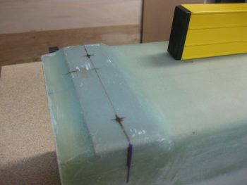
Drilling CS spar pilot holes

Here’s another markup on the inboard side of the strut.
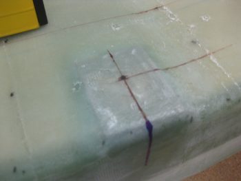
Drilling CS spar pilot holes

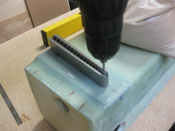
To ensure my holes are a good 90° to the face of the extrusion, I’ll be using my new drilling block.
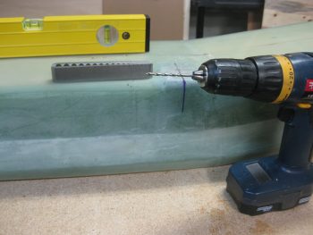
Drilling CS spar pilot holes

Below I’ve just drilled out the 2 outboard 1/8″ pilot holes in the spar on the right side.
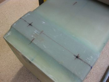
CS spar pilot holes drilled

And the same for the inboard extrusion.
CS spar pilot holes drilled

I then flipped the CS Spar around and started in on the left side.
Drilling CS spar pilot holes

Here I am using the drilling jig to keep the bit straight.
Drilling CS spar pilot holes

And Voila, here are the 1/8″ pilot holes drilled into the aft side of the spar.
CS spar pilot holes drilled

Then, as per plans, I marked up the front side of the CS spar for drilling the forward side spar boring holes.  I have to state that when I started on the outboard holes it wasn’t until I got around to finding the inboard hole to drill that I realized the spar was upside down to me… which my outboard holes were way off!  Not that it matters because these holes can be left open, and they’re close anyway that once I start using a 5/8″ bit they’ll go away… but it is somewhat of a testament of using a 1/8″ bit to start since it keeps the holes small & manageable.
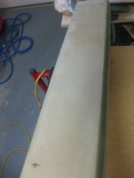
Front spar pilot holes drilled

Here’s a shot of the long 1/8″ drill bit that I put into place after drilling each forward spar face hole.
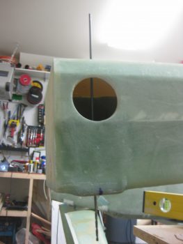
Front spar pilot holes drilled

I used a long ruler to double check the angle of the drill bit on each hole so as to ensure that the bit wasn’t heading into the wing extrusions at an odd angle!
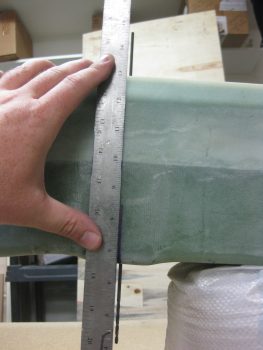
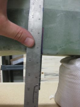
Aligning front spar pilot holes

Aligning front spar pilot holes

With Chapter 19 Step 1 of Step 11 complete, I then checked on the cure of the IBBS Clickbond glass.  The epoxy was pretty much cured, so I very gently popped off the IBBS unit.  Here’s the final shot of the IBBS Clickbonds glassed into place.
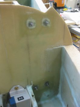
IBBS Clickbonds install complete

And here’s a trial mockup of the IBBS to ensure nothing is jacked up (which nothing was!) and to confirm clearance of the wiring harness & connector.
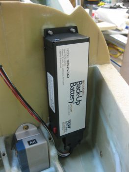
IBBS Clickbonds install complete

Finally, I got back to the nose Tool Box. I trimmed the edges with a Fein saw (earlier).
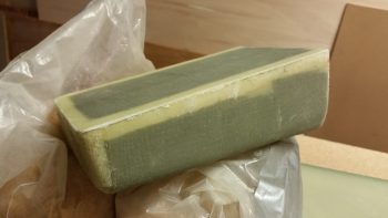
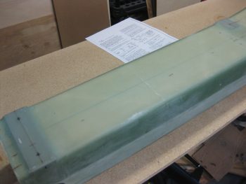
Tool box aft side glass trimmed

And then sanded them down.

Tool box profile view

As my last officially task of the night, I dug the foam out of the tool box that I had used for a form.  And then I cleaned up the inside just a bit.
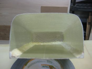
Tool box foam form removed

Then of course had to mock it up for a trial fit.
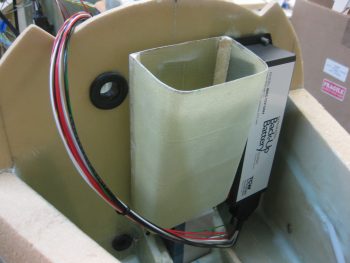
Tool box test fit

Here’s another shot of the nose tool box mocked up in place!
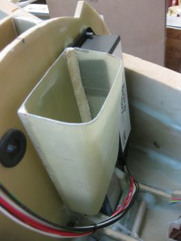
Tool box test fit

Ok, so tomorrow I’ll start leveling the wings and the CS spar to get them pretty darn close to perfect.  ONCE that happens, I will then start drilling the CS spar/wing bolt holes into the wing & CS spar!