Chapters 14/19 – Wings to CS Spar

I don’t have pics of today’s progress because it was pretty much all research and coordination.  Although I have been trying to get into the shop to get the wheel pants prepped, I think it’s more important to get the Wings mounted to the CS Spar, then the CS Spar mounted to the fuselage.  Then, finally, the last piece of mounting flight lift surfaces will be mounting the Canard to the fuselage.

I continued to consult the plans and research other builders’ techniques, taking special note of any builders tips and issues they may have encountered.  In addition, I had a good discussion with my local EAA Chapter 186 (Manassas, VA), and my buddies Marco and Mike Beasley.  Mike has finished all the major aircraft structures on his Long-EZ and is in the finishing stage, so he has amazingly valuable insight on how to do this.

The main topic of conversation I had with my EAA folks is in locating a suitable place to mount the wings to CS spar, etc.  They don’t have anything available at this point, so I’m in hunt mode for a good location with enough size that will allow me to complete these next few steps.  One reason why I’m focused on getting this done soonest is that the weather is forecasted to be pretty good here for the next 10 days, so I’d like to get moving of major pieces part done while the WX is cooperating.

Tomorrow I’ll make some more phone calls to find a good build location and should have my plan nearly finalized for these next few steps.


Chapter 13 – Flipping the Bird!

Since it was an unseasonably warm day today, I figured I had better get my glass cutting in while I can.  What does cutting glass have to do with the weather?  Well, I don’t like putting my bike out in the weather nor do I like opening the garage if it’s really cold outside unless I really have to.  So I rolled the bike out in the driveway and then had unhindered access to the cutting table.

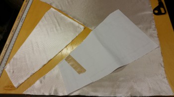
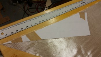
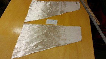
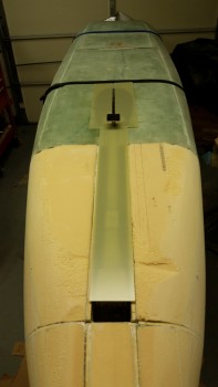
I’m using the same layup schedule as my buddy Ary Glantz used on his nose (with some additions) since per the original Long-EZ plans “fiber orientation is optional.”  I cut 4 panels to cover the entire nose, 1 panel covers from the top on the side down to the bottom side nose CL.  In the pic below you see 2 of these panels.  They measure 44″ front to back, 33″ tall aft and 5″ tall forward.  And as you can see again below, the stock width on a roll of BID is 38″, so 2 panels can be made out of a 38″ wide x 44″ long piece of BID.

Cutting bottom nose BID

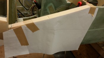
Because I sinned grievously by thinning my sidewalls on the nose, I added one extra ply on  the inside, and I will add 1 extra ply on the exterior side as well.  However, I am only adding the extra ply in the immediate area of the thinned panel, and not the entire nose.  To ensure I got the correct cut, I made up a template of the nose side panel.

Template for extra BID panels

I then used my template to cut out a ply of BID for each side, only this time I did go with the 45° fiber orientation to give it a little bit extra umph!  This ply of BID will not actually be the next piece of glass to get laid up on the nose after the two big side pieces above.  I will also be adding a ply of UNI to each side as well, as per below.

Cutting extra BID panels

As I stated above, I’ll be adding a ply of UNI to the bottom nose layup.  However, although there will only be 1 ply of UNI, there will be 2 actual pieces of UNI.  The top piece per side will have the major fiber orientation parallel to the top of the nose side piece.  So, in other words, angled down slightly.  These fibers will essentially act as cables (as all glass does, not trying to overstate the obvious here!) securing the cantilevered nose to F22.

To get this template, I merely chopped off the top part of my previous BID template.

I was about ready to cut the first upper UNI portion off my roll of UNI when my Spidey senses told me to stop!  I had almost forgot that I had a big tub of scrap UNI glass, and a lot of those pieces are fairly large.

Top UNI ply … wait a minute!

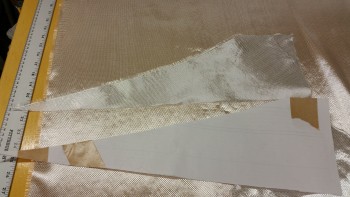
I quickly found that I had plenty of spare UNI pieces to use other than cutting this piece off the roll.

Cutting top UNI ply

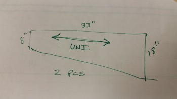
I then measured out the requirements for my bottom UNI piece that will get glassed into place with the fiber orientation horizontal.

Measurements for bottom UNI ply

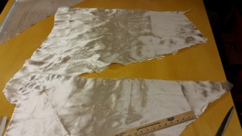
I found 2 more large pieces in my spare UNI bin so I took them out to assess them.

Bottom UNI plies … scrap glass

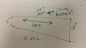
Somehow, and I’m not quite sure, my requirements for the lower UNI glass pieces changed!  ha!  Since the above pieces could provide me 28″ long pieces, I decided to simply shorten my measurements on my extra glass by 5″.  This puts the front of the UNI ending about in the middle of the battery compartment sidewalls vs the front of the battery compartment if it had measured 33″ in length.

Um, new #'s for bottom UNI ply…ha!

Here are the larger, lower pieces of UNI, one ply per side.  I thought it was pretty cool that I didn’t use one piece of UNI off my UNI roll!  This is all basically “free” glass.

Bottom UNI plies … scrap glass

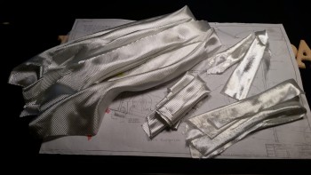
Below is a shot of all the glass for the layup on the bottom of the nose.  All the glass in the lower right hand corner is extra.  If you’re wondering how much extra weight that will add, it weighs out at right about 0.52 lbs.  Double that to get the approximate weight of the epoxy and we’re talking about a little over a pound in added weight.  With the amount of added strength it provides the nose (albeit I’m not an engineer), I’ll take the weight penalty!

All the nose glass

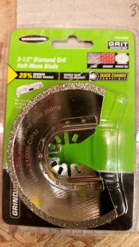
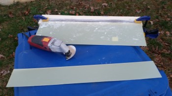
With all the nose glass cut, it was time to get one more outside task off the list.  When I went to Harbor Freight last night, I was considering purchasing a wet/dry tile cutting saw with a diamond blade since that’s what my research revealed as the power tool de jour for cutting G10 according to the online forums.  Well, even with the sale going on it would have been a bit pricey, at least quadruple for what I ended paying for this $11 diamond Fein saw blade.  I figured I would try this out and then if it didn’t work I would go with the more expensive option.

G10 blade?

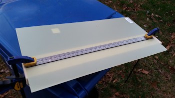
I marked my 1/16″ piece of G10 to cut off a slab of 3.6″ wide that I’ll be using for my nose gear strut fairing.

Test cut on G10 with Fein saw

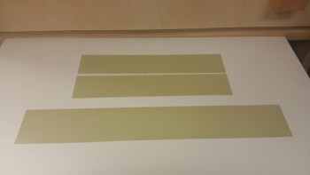
Cutting slow and using the metal measuring stick as a guide, it only took me a few minutes to cut right through this piece of G10.  Certainly, if this were a 1/8″ thick piece I think it would still do it, but it wouldn’t be nearly as pleasant of experience.

Voila! A nose gear strut fairing!

I ended up cutting a couple of rough 3″ x 16″ blanks for my nose gear doors as well.

Voila! Strut fairing & gear doors!

It was starting to get fairly dark when I was cutting my last G10 nose gear door, so I took my operations back into the shop.   With my outside activities completed, I started back on the nose area.  I trimmed the left & right corner reinforcement plates that I installed last night.  I also sanded all the un-peel plied glass edges to avoid any painful “gotchas” later on down the road.

Cured & cleaned right side reinforcement wedgeCured & cleaned left side reinforcement wedge

After vacuuming up the mess I made in the instrument panel area, it was time to make an even bigger mess by getting back to sanding the nose.  I pulled out the long board with 36 grit sandpaper and went to town.

Here’s a higher-up angle shot of the nose.

HIgher angle

Here’s the right side of the nose.  That divot towards the aft side of the foam is where I got a little too aggressive with the saw during one of my first initial cuts.  I’ll remedy that of course as I glass the nose.

Right side upper nose finished

And a pic of the left side as well.

Left side nose sanded & shaped

After the sanding of all the upper surfaces of the nose was complete, it was then time to flip the fuselage upside down.  I started by wedging the nose of the fuselage higher so I could remove the forward fuselage dolly saddle.

Front fuselage off saddle

Front saddle removed

I then did the same in the back, and here’s the result:

Fuselage secured on flat blocks

I loosened the tie down straps and slowly flipped the fuselage over onto its side.

Fuselage turned on side

Fuselage turned on side

Here’s a requisite nose shot with the fuselage on its side.

Fuselage turned on side

And then finally flipped it completely upside down.

Fuselage inverted!

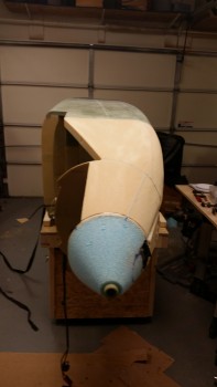
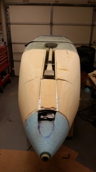
It’s amazing how big this bird looks now!  That nose really adds a lot of area!

Let's do some glassing!

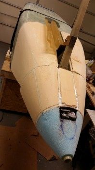
A view from aft.

Fuselage upside down

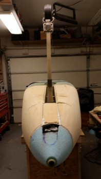
And a couple straight on shots, nose gear up & down.

Nose shot

Gear up . . . er, uh, down!

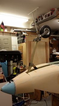
A side shot with the nose gear extended.

Gear down

I plan on getting the prefab nose gear cover (SC) installed tomorrow.

Strut cover mounted soon

And here’s one last shot with the G10 nose gear strut fairing and gear doors mocked up.  Can’t wait until those are on!

Strut fairing & gear doors mocked up

Tomorrow will be a busy day.  Like I said, I plan on getting the gear strut cover (SC) installed.  Before I can do that though I need to glass the underside forward NG30 cover nutplate assemblies, draft plate, etc.  I may need to increase the height of the SC as well just as I did the nose wheel box (NB).   As you can see, it will be at least one more day before I actually get to glassing the nose, which now I’m thinking will be Tuesday, but may be as late as Wednesday or Thursday.  Much to do, much to do!


Chapter 13 & 22 – Prepping for nose foam!

Yes, it seems to be taking forever to prep & install the ancillary components in order to facilitate item placement in the battery compartment.  But I am inching forward.

I started today by pulling the peel ply from the Battery Buss & the E-Buss control relay mounting pad 1-ply BID layup that I did last night.  The layup turned out fine without any issues, so I cleaned it up and then drilled out the saran wrap plastic in the 6 embedded nutplates.    I’ll tell you, this small stuff is the stuff that turns into time busters, since there’s so many little steps.  And at the risk of sounding obnoxiously repetitive, that’s why I want to knock it out during the build –as well as for component planning purposes– so that I don’t end up with a completed airframe with no idea what I’m putting where!

As you can see, I also reinstalled the brake lines.  I’m skipping ahead here, but since this info is germane to the brake lines, I’ll tell you that I’m going to have to redo my service loops.  After doing an hour or so research on the next steps for the brake system, like the parking brake install & brake reservoirs, I stumbled across some stuff that I either missed or just wasn’t in the Tony Bengalis’ books.  Mainly that there should be no sharp bends in the brake lines and to keep it straight as possible.  Since I ran across a bunch of ACTUAL loops in steel & aluminum brake lines in my recent research, I figured about half a sine wave would be less stress inducing than a full 360° loop, but I guess any sharper type curvature is bad, so I’ll be remedying that soon.

Battery Buss & Relay mount pad

Clearly I’ve been giving my electrical system a fair amount of attention.  The main effort here with this mounting pad was to get the battery buss on the aft side of Napster (the F1-3 bulkhead) to minimize the number of wires going through Napster.  In addition, it utilizes space that up until this point was unclaimed, but some good real estate.  Finally, with the battery buss installed, I get a much clearer picture of where my holes need to go for the multitude of wire heading to the north end of the nose.

To get a minor jump on my electrical system, I went ahead and wired up the foundational wire runs between A) the battery contactor & the battery buss, B) the E-bus controlling relay to the battery buss/switch/E-Bus.

The work on the Battery Bus area included labeling the buss and the wires, crimping on the correct terminals, and confirming wire sizes and wire lengths.  Speaking of wire size, I committed a sin against Bob Nuckolls’ teachings since after reviewing my electrical wiring requirements I finally realized that I have a lot of long 14 AWG wire runs.  The feed from the Battery Buss to E-Bus is ID’d as a 14 ga wire, but since I had an extra 10 ft or so of 12 ga red wire, I used that instead.  That frees up my 14 ga wires for the really long runs where it would be a heck of a lot heavier to sub a higher gauge wire for the length of the fuselage, compared to the 2-3′ that I just did.

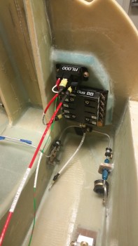
Below is the Battery Buss ATC fuse holder (bottom) and the B&C S704-1 relay mounted above the buss.  The large red wire heading back toward F22 is the power wire from the relay to the E-Bus, which is normally unused unless the scenario I described last night plays out where the main alternator is cooked, fried or somehow otherwise inop.

The white wire on the bottom center post of the battery buss is the 10 ga power feed wire connecting to the battery contactor just on the other (fwd) side of Napster.  This white 10 ga power wire will traverse Napster through one of the 2-3 holes that will all get drilled either below or to the right side of this new mounting pad.

Also, just an FYI for those folks not familiar with this system.  The Battery Bus is so named because it is the only buss that is always hot with live power.

Battery Buss & Relay mounted on pad

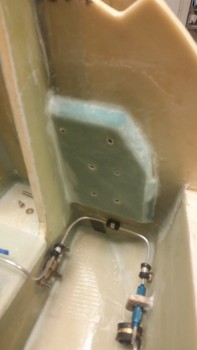
Tomorrow I plan to work on both the brake system and the getting the nose battery compartment are foam panels installed.  Well, at least the battery compartment floor pans.


Chapter 13 – The AEX Killer

Yep, that’s me!  Or maybe I should have titled this post, “The Anatomy of a Repair.”

I had committed two grave sins in the wiring of the AEX P2 connector, one on each side. On the switch side I found pin 1, inserted that wire and then started filling in the wires per color from pin 1, first across and then down.  The only problem was that my first direction was as it should be if I was looking on the FRONT of the connector face, versus the mirror image it should have been on the back plate of the connector.  Ooops.  Well, as I said yesterday, I caught that after my discussion with Jack and remedied it.

What I didn’t catch was the wiring mistake I made on the AEX side of the P2 plug.  When I had original diagrammed out the connector pins for that side, I realized that I hadn’t made the diagram in the normal top row=1-3, middle row=4-6, bottom row=7-9 pattern.  If you took the diagram and flipped it 180° from the upper right corner down to the lower left corner, that is what I ended with: column A= pins 1-3, column B= pins 4-6, column C=pins 7-9.  Thus, when I wired it up (mistake #3 actually, since it was LATE at night) I had the mental picture of the initial diagram (left below) in my head, not the correct one (right below).
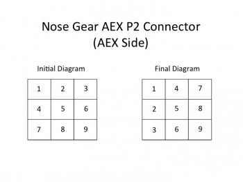
AEX P2 Connector

I got ahold of Jack later in the afternoon to figure out the wiring issue with the electrical nose gear actuator.  With the AEX presumably Tango-Uniform, I thought that perhaps I needed another jumper on pin P2 along with pins 5 & 6.  I wasn’t sure about the jumper situation due the fact that since I ordered the AEX with my initial order of the gear actuator, I never received a jumper plug.

After some discussion Jack told me that if P2 pins 5 & 6 jumpered wasn’t getting the nose gear actuator to go back up, then I should try a jumper across pins 1 & 4.  Ok, I had the plan and was ready to execute.  I got off the phone ready to throw a jumper across pins 1 & 4.  Uh, the only problem was there was no pin 1.  The switch side of the P2 connector has 9 pins, and pins 1 & 2 are empty!

I called Jack back a few minutes later and gave him my report.  With that knowledge in hand, along with my trusty Fluke, Jack began to guide me through checking voltage readings from points A → B, X → R, etc.  I checked the relays by holding them up to my ear as I flipped the switch and was pleased to hear an audible springy click.  We checked the up-travel microswitch since this was the primary culprit: 12.86V on both sides.  All good.  Then I checked the main power wires going into the actuator motor.  12.86V on the red and .005V on the ground… all good.

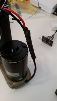
We were both stumped and Jack concluded that it appeared that the motor was bad. The problem was that these motors are amazingly robust and have an extremely low failure rate. Jack asked me to locate the heat-shrinked power connectors inches from where they exit the motor housing.  I did.  He then asked me to give all the wires a good tug to make sure they were connected nice & snug.  They weren’t.  The wires closest to the motor came out with the slightest pull.

That, my dear friends, seemed to be the real issue.
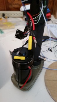
Fixing motor wiring

I asked Jack if I could run power straight to the motor with the inline fuse on the power side and he said yes.  When I did, I was pleased to have the motor jump to life.  Issue found!

(Thanks Jack, for such a great job talking me through the troubleshooting!)

[Note: Some of these pics are blurry since I’m using my phone camera … sorry.  I guess phone cameras are made these days primarily for taking selfies to post on FaceBook!]

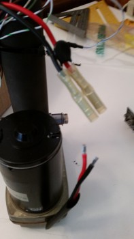
As you can see in the pic below, the yellow butt splice wire connectors are more automotive grade, which should have done the job ok, but for whatever reason here they didn’t.

Since the butt splice connector on the black wire was firmly in place, I started with replacing the one on the red wire.  I was able to pull it off with a firm pull.
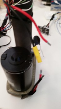
Fixing motor wiring

I then spliced on a higher grade butt splice connector that came in an electrical connector kit that I bought from B&C.  You can tell the difference between the two immediately in the pic below.
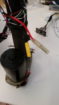
Fixing motor wiring

With the red wire butt splice in place, I then pulled the old connector off the black wire and crimped a new butt splice connector in its place.
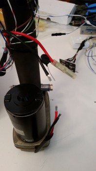
Fixing motor wiring

Fixing motor wiring


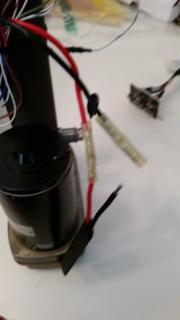
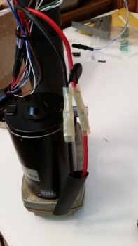
With the switch side completed, it was time to crimp the motor side wires into the butt splice connectors.  I had already found an appropriate sized piece of heat shrink and slid it into place before completing the butt splicing.

I crimped the red wire butt splice first, and then finished with the black wire.  It’s not easy to see in the pics, but the space that I had between the wires and the motor housing was fairly tight to get my crimper in place while still ensuring that the wires were fully seated into the butt splice connectors.
Fixing motor wiringFixing motor wiring


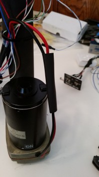
I pull tested all the wires to ensure they were securely crimped in place, then proceeded to cover my work with the good sized piece of heat shrink that I had pre-installed.  I used my heat gun to shrink the heat shrink in place.
Fixing motor wiringFixing motor wiring


I then secured both ends of the heat shrink with a zip tie.
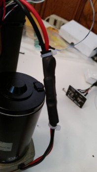
Fixing motor wiring

And then zip tied the newly spliced wires to the motor housing.  As I was doing this the lower (in these pics) zip tie slid off the heat shrink so I simply cut it off.
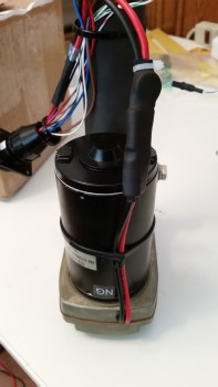
Fixing motor wiring

Here’s a comparison of the butt splice connectors: old left, new right.
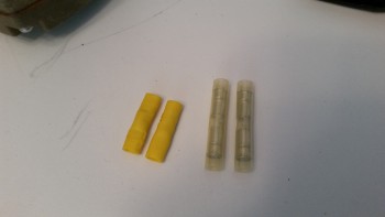
old vs new splice connectors

With my repair completed, I hooked up the wiring harness, sans the AEX and with a jumper wire in place between AEX P2 connector pins 5 & 6, and hit the switch.

Ahh, sweet success!  The actuator motor came to life and up it went!

With the nose gear actuator back online, I took a quick break to unearth my layups from last night and clean them up.  I pulled the peel ply & razor trimmed the edges.  Here’s the final results.

So, after some minor cleanup sanding, both BC1s are ready for install as is the draft plate. [Note: since the draft plate is simply just that, a plate to keep the cold air from entering the NG30 nose gear box, I intentionally laid it up dry.  I did this by peel plying each side but then adding very little epoxy.  Again, since this plate isn’t intended to be structural, this keeps it as light as possible.]
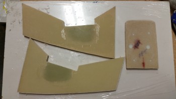
Round 2 glass completed

I then grabbed my tube of grease and applied a thin film to the nose wheel bracket stem before reattaching the nose wheel assembly to the NG15 bracket on the end of the gear strut.  I reattached the gear strut in place to the NG8 pivot hard points on the NG30s. Finally, I pulled out the NG3 & NG4 brackets and played around with those for a few minutes to get an idea of how they would fit (NG3 is shown on the gear strut & NG4 is sitting on the work table just to the right of NG3).
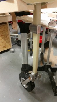
Nose gear strut with wheel assembly

Lastly, I installed the nose gear actuator into the NG30 nose gear box and wired it all up.  I took out my ruler and did a rough measurement of around 6.75″ from the center of the NG6B attach bolt down to the center of the NG4 bracket.  I then made a small tick mark on the gear strut at the top edge of the NG4.  I clamped the NG4 bracket in place (not shown) and tested the gear going up & down.  When I ran the gear up the first time I stopped it just below the F22 channel and then raised it a few bursts at a time.  This was to ensure that A) the gear strut fit the F22 channel and cleared the sides, and B) the gear wasn’t going to crush the floor of the fuselage.

I was absolutely pleased that the wheel fit perfectly in the wheel well and that the gear strut stopped just shy of kissing the fuselage floor in the nose gear strut channel.  In addition, the front of the wheel (bottom as it sits in the wheel well) was just above the bottom surface of the fuselage by about 0.07″.  I had meant to take a pic but apparently I didn’t.

So out of the gate things were looking pretty good spacing-wise with the nose gear.  But when I cycled the gear a couple of more times I noticed that everything wasn’t looking as spiffy as it did the first time around.  And then I found the culprit.  The NG4 bracket had slipped slightly since I apparently hadn’t tightened the clamps down securely enough. No worries, I’ll finalize the gear travel later and then move onto mounting the NG3/NG4 to the gear strut.
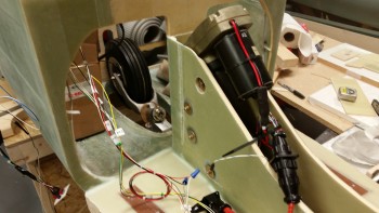
Gear actuator motor installed

Although the gear troubleshooting was a real PITA, in hindsight I’m glad it all happened. Besides upgrading a critical failure point (apparently), I learned an immeasurable amount of information about my nose gear actuator system wiring.  Instead of just barely getting through the wiring to get it to work and then moving on to the next task at hand (to be clear: I’m speaking about me here, and in no way mean this to slight other builders!), I feel like I have a really good solid working knowledge of the nose gear actuator wiring now.

The next steps will include widening the F22 gear strut channel on the right side very slightly and then getting the gear up/down travel dialed in.  Once the gear travel is good, I’ll be permanently mounting the NG3/NG4 brackets to the nose gear strut.



VSWR what?!

In the December 2013 edition of Kitplanes magazine I found yet another useful piece of information, and like so many other times during this build, it came a year or so too late. The article was written by Jim Weir–maker of many canard antennas–and discussed checking the VSWR (Voltage Standing Wave Ratio) of each antenna before burying it under the skin of a plastic airplane such as the Long-EZ, at which point if you have a problem . . . well, better think up some good solutions!

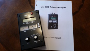
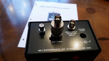
Jim recommended a MFJ-259B Antenna Analyzer to check the VSWR on each antenna to ensure they were good.  Again, my antennas already being installed, I still wanted to check them to A) know if any had a VSWR too high to count as good, and B) pick the best between the COM antennas for COM1, and the best between the NAV antennas for NAV1.  The goal is a VSWR ratio less than 3:1, because anything higher is a lot electrical energy traveling back along the OUTSIDE of your antenna coax cable to the transmitting device (ie, radio), which will drive your available Tx wattage to unacceptably low levels and could damage your transmitter in the process.  In addition, as with so many other units of measurement in the weird & wonderful world of electrons, VSWR readings are logarithmic.  Any increases above a 1.5:1-to-2:1 ratio and things start getting real hairy real quick!

I of course started hunting around for a good, used antenna analyzer at an acceptable price anywhere I could find one.  That pretty much drove me to eBay, where I picked one up for about half the price of a new one.  And thar she be below.

MFJ-259B Antenna Analyzer

The only problem with my newly won prize (which I actually bought a while ago), was the antenna cable adapter that came with it.  These analyzers can be used for checking any antenna and are common in the HAM radio world, so perhaps the antenna cable adapter that came was used for something even more exotic by a HAM radio bubba.
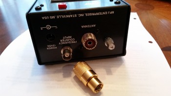
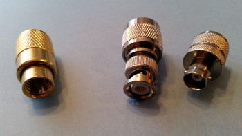
Old Connector ???So although I didn’t know what the mystery adapter was used for, I did know that to check the BNC connectors used on the Long-EZ antenna cables that I would need a BNC adapter for the antenna analyzer.  So, last week I ordered a couple of them, one male and one female, and I got them in today.

New BNC connectors M & F

You can see the new BNC antenna cable adapters on the right, and the old one on the left. Below is a shot of one installed on the antenna analyzer.

It fits!

Since the weather is still too cold to economically heat my workshop for glassing, I plan on terminating all my antenna cables with BNC connectors and then checking the VSWR of each one with this MFJ-259B antenna analyzer.

Chapter 6 – Fixing Fuselage Damage

Today I trimmed and prepped the damage area at the lower left side of the fuselage.  Note the line straight down from the middle of the foam insert piece: this is where the fuselage was cracked and was the first thing that I repaired.  Now you can see why, since the fuselage side had to serve as a support element to keep the new insert aligned and true.

Lower left fuselage repair

I micro’d the foam repair insert into place at the foam-to-foam junctions, but where the fuselage bulkheads are located that abut the new foam inserts, I actually used flox for more structural oomph.  I actually did that on the right side as well.  I just failed to mention it before. Continue reading →

Unpacking the Boat (AKA “Fuselage”)

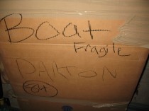
Today starts the actual unpacking of the boat, or shall I say, the fuselage.  Apparently my next door neighbors thought it would be cute to pull a fast one on me!  When talking in my garage/shop one day, they asked me what I was going identify this “thing” (said snidely) sitting in my garage that I was going to send over to Germany.   Well, a few weeks earlier I had seen on one of the blogs where a guy had shipped his fuselage as a “boat,” which I thought was pretty darn funny.  So I snarkily (it’s a habit of mine!) said, “a boat.”

Well, due to a scheduling SNAFU in Virginia, the movers had picked up my fuselage while I was at the firing range.  Luckily,  my ‘trusty’ neighbors helped out with overseeing the movers pack my stuff.  Well, apparently they told the movers it was just, in fact, a boat.  What made it really funny was fast forward three months later in Germany when one of the guys unloading the truck asked me where I wanted my “boat.”  I thought his English was a little shaky!  After a few repeats, and a growingly impatient mover, I finally understood what he was saying and ran out to the moving truck to see them, in fact, lowering “a boat” out of the truck!  Well played my friends . . . well played!

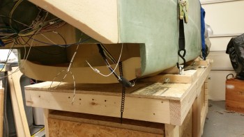
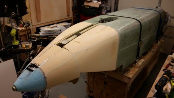
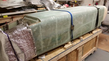
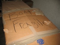
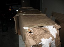
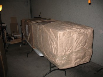
Below are pics of unpacking “the fragile boat”!!!

Unpacking the fuselage (aka "boat")