Chapter 6/13 – Yep, I did it!

I started off today taking a gazillion more measurements, and checking out other builders’ sites on their canopy positioning and inboard elevator root fairings.  After getting my comfort level significantly higher on the whole of the plan working (at least on paper!) I got to work cutting out some 3/8″ PVC foam.

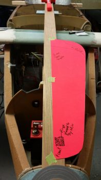
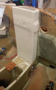
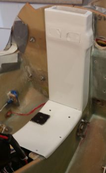
The first piece was for an intermediate bulkhead that I’m going to install just forward of the canard, which will look bow-shaped and will essentially serve more as both as a bit higher strength cap to the blue foam going in forward of it, and as a demarcation point for the avionics bay/nose cover going aft.

And yes, you read that correctly.

I will be incorporating a flip-up/removable cover for the canard and avionics area forward of the instrument panel and aft of F28.  It will also overlap the panel going aft so that the canopy will physically lock it into place when closed (that of course is not the only securing method on the aft side).
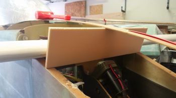
More on the avionics bay/nose cover below, for now here’s another view of the intermediate bulkhead that I’ll be securing into place before the nose foam is put in place.
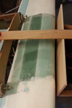
I also cut out a 1.8″ wide strip of the 3/8″ PVC foam that will be the front piece of what is roughly a picture frame looking foam rectangle that will be floxed and glassed in place for torsional strength of the upper forward fuselage between the panel and F28, and the upper longerons on each side.  It will essentially be an interconnected “C” channel (just sandwiching foam in this configuration) around the entire edge of the avionics area, with all the glass locking the 4 sides (and corners) together.
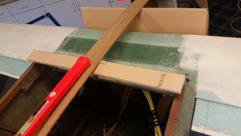
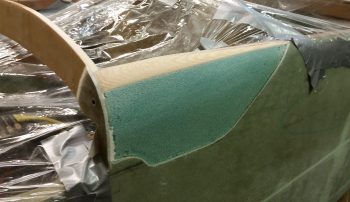
Another shot of the nose/avionics bay reinforcement piece, which is the first of 4 separate side pieces to be installed.  This design will allow for a significant opening in the top for access to the avionics forward of the panel, which will all be enclosed by the removable cover that extends from the front edge of the canard to just aft of the instrument panel.
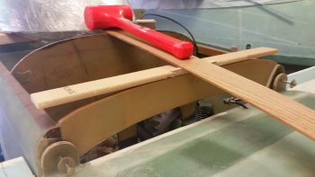
I’m aware that this design is deemed a bit controversially by some builders and Canardians, but I’ve studied a number of designs and am mitigating any induced weaknesses to the airframe structure by implementing it.  In fact, I honestly think that my design will be significantly stronger that either the plans version or by simply having an avionics access hatch cut in the top of nose just forward of the canopy/instrument panel.

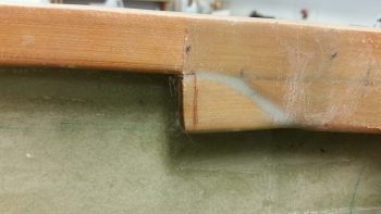
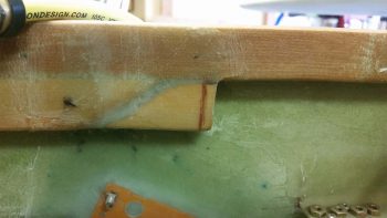
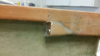
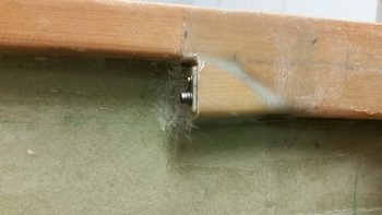
Part of my decision process today was to come to a final conclusion on exactly the design and configuration of the sides of the aft nose and avionics bay cover.  My design uses some what of a split elevator fairing where the fairing itself is integral to the cover and then secures to a very robust bottom segment of the fairing via a screw up through the bottom securement tab into an embedded nutplate on the underside notched portion of the fairing.

Where the trailing edge of the elevator fairing intersects the fuselage sidewall and the inherent transition fillet on the underside of the fairing where the determinant dimensions for both the aft and bottom edges of the aft nose/avionics bay cover sides.  After RE-reviewing a number of Berkut, Long-EZs and Dave Ronneberg designs with nose hatches, I settled on a simple angled transition from cover to fuselage at the instrument panel external fuselage area.
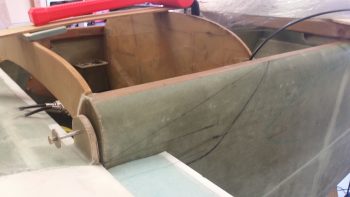
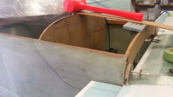
I double and triple checked all the possible associated variables and potential issues I could think of, and then I made the plunge.  I made the final design version on the left side of the fuselage, then traced it to transfer it to the right side.
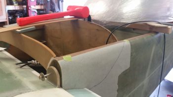
Which you see is completed here . . .
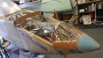
I then took my wide roll of packing plastic and wrapped up the nose from tip to instrument panel to protect the innards from errant fiberglass, foam and other nasties.
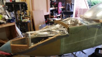
I then loaded a fresh blade on my Fein saw and got to work on my respective fuselage sidewall surgeries.  My goal was to cut just enough in depth to cut through the glass and not get into the foam underneath.
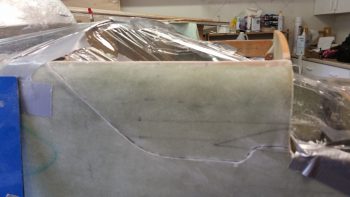
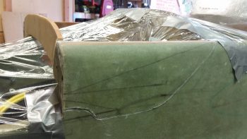
If I had any doubts as to how secure my glassing was on the fuselage, this endeavor laid that to rest.  It took a good 20 minutes minimum on each side to get the glass pried off while being careful not to damage the foam underneath.
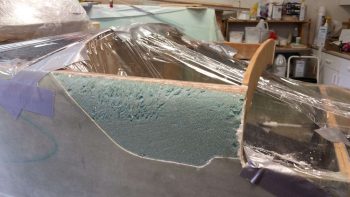
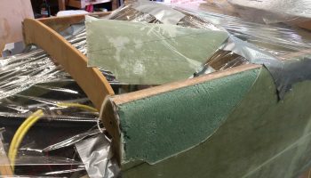
The action here was actually a 2-part task in that not only did it expose the areas on the upper/forward fuselage sides that will allow me to create depressions for the aft nose/avionics bay cover, but also to correct my previous non-shaping of the front “corners” of the fuselage that should have been significantly rounded over before the fuselage exterior was skinned.
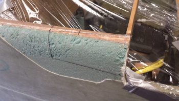
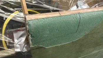
In the summer of 2012 I glassed the exterior of the fuselage without having caught the requirement to round the very front of the longeron and nose sidewall foam, as you see that I’ve just done on the right side (left pic below) vs the way I had it (right pic below). Yes, I was living in blissful ignorance until Marco went to glass his fuselage, at which point he queried me about it.  I gave him my incredibly well thought out reply of, “Huh?! What are you talking about?!”  Followed a bit later by, “Ah, <enter appropriate expletive here!>”  To see a great explanation of this, check out Marco’s blog.

As for the aft nose/avionics bay cover, I will be laying up glass back onto this exposed foam area with overlap back onto both the existing fuselage sidewall glass and onto the new aft nose/avionics bay front reinforcement structure (“picture frame”) that will be in place between the panel and F28, and the longerons on each side.  This will serve not only to replace the structural element of the previously removed sidewall glass, but tie the fuselage sides to each other via the reinforcement structure.
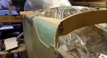
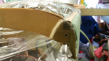
So here’s my shaping the forward top longeron intersections with F28, with the right side (left side of pic) nearly finished and the left side still untouched.
I then finished the forward top longeron shaping to about 90%.  I still have to do a tad bit more dialing-in so that both sides match in shape, but it was late, I was tired of sanding and sanding with a hard board is amazingly loud, so I wanted to take it easy on my neighbors and finish the final 10 minutes worth of sanding tomorrow.  I also need to finalize the depth of my sidewall depressions in the exposed foam.
Here’s another shot of my shaping the forward top longeron intersections with F28, with both sides shaped this time around.
Yes, I should have taken a picture of my shaping and prepping of the aft nose/avionics bay front reinforcement piece before I floxed/micro’d/5-min glued it in place. This pile ‘O stuff is simply to keep the various parts of it weighted down <correctly> since the aft end of this piece is ever so slightly raised to match the downward angle from the panel to the F28 bulkhead.

This contraption (aka “convoluted pile of crap”) right here is exactly why I decided to set the 4 sides of this internal reinforcement frame in individually, since the installation of each side/edge has it’s own unique requirements and challenges.  Once all the pieces are floxed/micro’d in place, I’ll do a final sanding & shaping of the new “one-piece” structure and glass it in place as one unit.
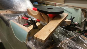
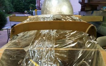
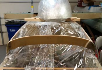
Here’s a straight on view of the aft nose/avionics bay front reinforcement piece.  As you can see, the center section is situated and mounted on the top edge of F28, where the outer 30% on each side is then even with the top edge of F28.  This gives me just a tad bit more height in the center area of F28 for a good nose angle flow from the panel to nose tip as it traverses F28.
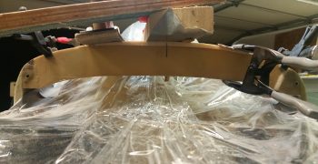
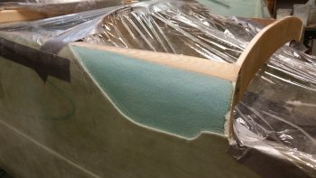
And a couple more shots of the aft nose/avionics bay front reinforcement piece on the left side.  The transition from the piece being on top of F28 to simply adjacent F28 is underneath the taped popsicle stick securing the bonded mating surfaces, but you can make out the foam piece floxed in place at the F28-longeron corner junction.
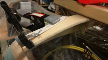
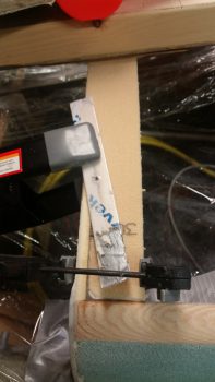
Tomorrow I will continue my work on the nose structures to get them installed and glassed in prep for starting on the actual nose structure and nose cover build. I would estimate in the next couple of days I will also start on some preliminary canopy installation tasks.
 

Chapter 13 – Nose job

I started off today working on my AC unit for a couple of hours.

I then got around to some wet sanding and painting on the oil “tower” box lid, and then some wet sanding and clear coating on the box portion itself…. both endeavors were rife with annoying issues and the outcome of each one is yet to be determined.  I suspect that there is a fair more work to get the surfaces dialed in to an acceptable (not perfect!) level.

Today was really more of a research & modeling day to tie together all the loose ends and integration questions I had regarding the nose.  I set up the canopy in its near-final configuration and then got to work on the nose.  I took a fair amount of notes and changed my hand drawn plans to account for the finalized dimensions, angles and curves.

Some outstanding questions I answered was that, A) I’m extending the height of F28 0.4″ at the center line, and B)  I installed (with duct tape) a 0.9″ gap-filling piece to account for the depression in the Napster bulkhead.  When the nose is final this gapped area will be filled by the thickness of the nose hatch.

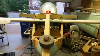
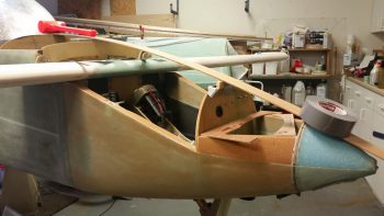
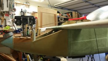
It may be a bit hard to get an exact idea with the big roll of duct tape on the nose, but this is outline of the upper nose.

Here’s a shot for the left side.  This provides a better depiction of the nose’s top curve.

And a shot from the front.

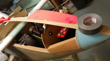
I then taped in place the nose hatch template (which is currently only half the hatch) to assess its size, shape, accessibility, etc.  As a point of note, the dimensions and shape of this particular nose hatch template is based off the Berkut nose hatch…. at least it started out that way!

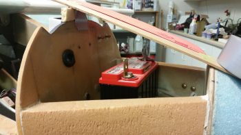
I then set the battery in place to ensure it would fit.

Regarding the battery, I assessed topside cable clearance and clearance for removing and installing the battery.  The PC680 battery is around 7.1″ wide and my nose hatch at the narrowest point above the battery with this shape and configuration would be 7.8″ wide.

Here’s a shot of the left side nose hatch template taped in place.

The above is somewhat of a quick overview of my planning process.  Again, I took a myriad of measurements, checked angles and clearances, then made quite a few notes and annotated drawings and pics I have of my nose design.  There are a number of things that I will cover as I build since it would difficult to provide overviews without pictures of the components and build process.

One such area –that happens to need correcting– is the very front top corners of the fuselage where each side intersects with F28.  I’ll cover that tomorrow as I go through the process of remedying my 6-year old error.


Last 2 days . . .

Just an update on my build and related non-build activities today and yesterday . . .

I started out yesterday by wanting to get a quick round of paint in before the multi-day bout of rain and T-storms rolled into the area, which were scheduled to start mid-afternoon.

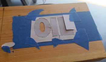
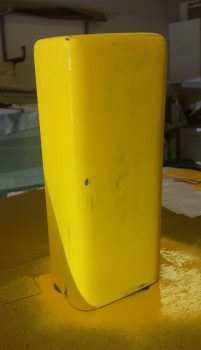
I wanted a label for my oil box that, quite conveniently, would identify the box as “OIL.”  I had thought about it a number of times while building the box and just decided to do it in a quick and EZ manner.  I painted the lid top black and then –using PowerPoint– made up a good sized block lettered version of the “OIL” label.  I then taped my “OIL” stencil pattern to a wide piece of painter’s tape and carefully traced the letters with a razor knife.

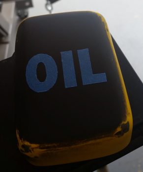
I then simply affixed the painter’s tape block letters over the black painted lid top.

Again, not absolutely perfect, but I’m not building an oil box, I’m building an airplane so I want to get this thing off the plate of things to do.

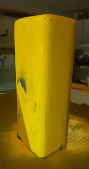
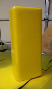
I then shot the oil box and lid with a few coats of yellow paint.  I added an extra coat for extra measure so that when I wet sand it, the carcasses of all the tiny little divebombing gnats that apparently love yellow so much they’ll literally die for it . . . would not show up in the final paint.  I guess painting this during the day is like being a big boxed food manufacturer, lots of bugs for added protein!

I let the yellow paint cure for about a half hour then brought the parts inside.  By the time I grabbed my keys, wallet and phone to head out to Harbor Freight for some consumables and check out some tools, the rain started.  While out, I also stopped by Lowe’s to pick up a long 3/4″ x 1/8″ piece of aluminum to use as a spacer on the longeron for the canopy build.

Now, the rest of the story….

When I returned from my errands I was ready to get back to work on the build.  I checked my task list and at the top was a note to call U-Haul to reserve an auto hauler trailer for moving the fuselage down to NC.  Time was a bit critical in that U-Haul has different rates for summer than the other 9 months of the year, with the summer rates being about 3 times the price as the rest of the year.  The demarc date for this price increase is Memorial Day, but as long as you reserve the trailer (or truck, etc) prior to Memorial Day you still get the significantly lower rate.

On the phone with the U-Haul bubbas they then asked for the year, make and model of the vehicle I was hauling.  Since I like to be up front about stuff but also realize the bias companies have against catering to anything aircraft related, I told them it was for a wheeled project I was working on.  The bottom line ended up that if it wasn’t a standard vehicle with a normal make and model, they simply would not rent me an auto hauler trailer.  I’ll spare you my commentary on what I think about our current social mores.

Concerned, I then spent a few hours investigating possible courses of action that would facilitate and result in my ability to move my fuselage down to NC.  This of course included researching what constitutes “wide loads”  for both Virginia and North Carolina.

In short, all things considered, my build endeavors were done for the evening.

After the detour I took yesterday, I started off this morning by heading to a local ma & pa diner to have breakfast and list out my tasks for the day.  I had to make a couple quick stops and by the time I returned it was HOT in the house.

I haven’t had my AC on (due to my cheapness…ha!) but it was time to deal anyway with an AC issue I’ve been having, which I finally deduced as most likely a clogged evaporator drain (all evidence points to this being a side effect of the AC drain being filled with rocks and garbage [I was told most likely the building crew] that was discovered by my tenant while I was in Germany… not only did it physically block the draining but facilitated the growth of algae, mold, gunk, etc. that blocks the drain line and forces the water to exit where it can out of the unit).

Again, due to my cheapness, and not wanting to pay the extortionist HVAC guys a ton of money only since they know the simple magic and I don’t, then I went into quick apprentice mode on becoming an HVAC “technician.”   Anyway, I believe I found the issue and thus had to go into HVAC repair/maintenance mode.  This is not only for my immediate comfort, but something I would have had to address anyway to sell the house…. so the work gets done either by me (on the cheap) or by a certified technician (muy expensivo!). So far the progress has been good, but it will take a few hours a day over the next few days to really clean up some of the rust in my drain pan, clean the drain lines, etc.

So that, folks, is where I am on the build…. and the move.


Chapter 12/13 – Final Canard Install

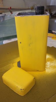
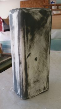
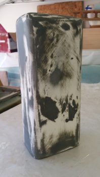
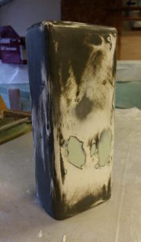
I kicked off the day spending a little over an hour on the yellow Oil “Tower” Box in its continuing evolution.  I started by wet sanding the yellow paint to make the surface even more uniform than it had been before.  Although I’m not naturally a patient dude, that’s exactly what is called for when finishing parts that don’t start out nice and uniform in shape to begin with.

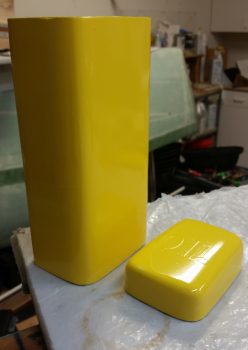
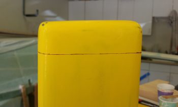
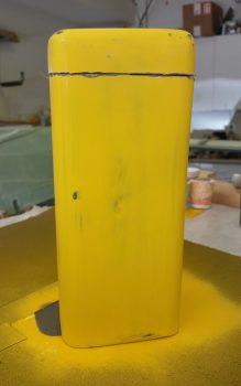
After a good wet sanding I then marked the cut line that will separate the box into the lower quart oil bottle (and shop rag) storage part and the lid top, which will have a hinge mounted on one narrow side with a twist-lockable clasp on the opposite narrow side.

I then used my Fein saw to carefully cut the lid top off.

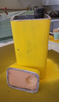
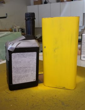
Here’s the lid off the top with just the tip top of the oil bottle peeking out and another shot showing the foam plug that I used to create the rounded edges & corners of the lid top.

I then removed the lid top’s foam plug and tape and quickly rough-sanded the inside to knock down some “gotchas” ready to devour unprotected flesh.

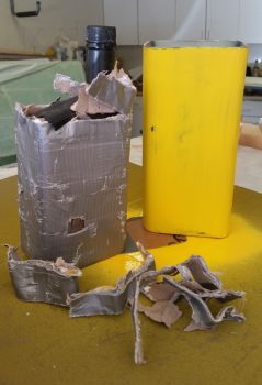
I then spent a good 20+ minutes extracting the empty quart oil bottle and associated cardboard and tape that served to make up the plug for the oil “tower” box.

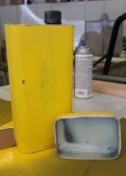
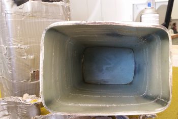
Here’s the inside view of the oil “tower” box.

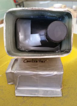
I had to cut 3 sides of the top part of the oil bottle to get it and the tape removed from the inside of the box, so I taped the bottle back together for a quick test fit… which I was very pleased with since the oil bottle fit is like a hand in a glove.  Ever so slightly snug just to keep the oil bottle from any inadvertent movement.

Then, just a quick double check on upper clearance –and for my own satisfaction– I placed the lid back in place on top.

I then prepped some BID, whipped up some epoxy and laid up some internal corner plies of glass in the long side corners of the Oil “Tower” Box.  I then peel plied the layups.

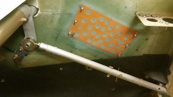
I also had prepregged 1 ply of BID and 1 ply of UNI to layup on the forward side of the elevator up travel control stop.  I decided that this would be strong enough with just the foam tab piece sticking out 90° from the sidewall and scrapped glassing in the perpendicular triangular piece that I had cut for this setup.  I then of course peel plied the lay up.

To keep the blog on track topic wise I’ll fast forward a few hours and show you the forward layup on the elevator up travel control stop, where I’ve pulled the peel ply and trimmed up the edges.  Nice and simple, and strong, and it works a treat!

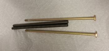
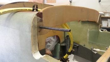
I then gathered up my two long (and quite expensive) AN3-62A canard upper mounting tab bolts along with their associated thin-walled 4130 tube sleeves.

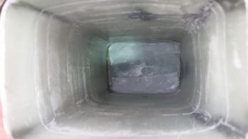
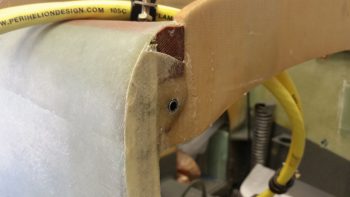
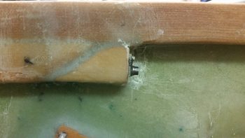
I ran a long 1/4″ drill bit through the holes to ensure they were nice and clean with a good diameter to fit the sleeves, at which I point I used straight epoxy and very wet flox to install the bolt sleeves into the holes through the F28 longeron doubler and the squared-off extensions I added.

Here’s the final install of the right bolt sleeve into the right F28 longeron doubler and the squared-off extension.  The left was the same as this.

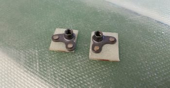
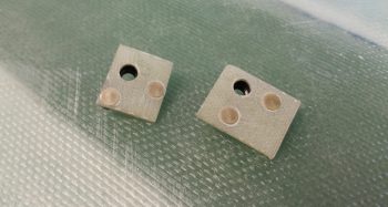
While the canard upper mounting tab bolt sleeves cured in their new longeron doubler locations, I then whipped up some K1000-3 90° nutplate assemblies using spare G10 Garolite pieces I had on hand –which I didn’t even have to cut! (How’s that for being laz… er, efficient?!)

BTW, I didn’t make them match in size because I prefer the larger sized one with bigger surface area to grip the flox, but the smaller one would of course work as well.

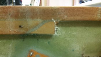
When I did a final fit with the canard in place, I must have been off a hair in my initial measurements with the bolts, since after install their would be no thread showing on either side.  Hmmm…. clearly the longeron doubler would need to be trimmed because I wasn’t forking out even more cash for longer bolts.  I just wish that I had figured this out prior to installing the 4130 sleeves!

Once I set myself to the task it really wasn’t that big of a deal.  I started by drilled a small series of holes just a few millimeters apart.  Then used the Fien saw with a straight blade and narrow wood chisel to remove the wood and glass from around the protruding 4130 tube, respectively for each side of course.

I then used a cutoff wheel on my Dremel to make quick work of trimming down the protruding thin-walled 4130 steel tube sleeve on each side.

I then test fit both sides and it looked as if my trim job had done the trick to provide me with enough thread exposure to ensure a good bolt fit.

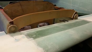
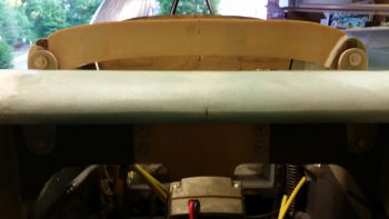
I then technically mounted the canard for the first time ever! (In regards to its final configuration… <grin>)

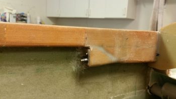
It was hard to get both top and bottom canard mounting bolts showing with the lighting, but here’s my attempt.

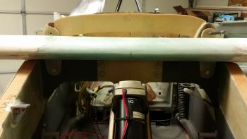
And here are the canard upper mounting tab bolts’ nutplate assemblies floxed into place on the aft end of the (trimmed) F28 longeron doubler extensions.  Admittedly, I got a bit more thread on the left side than I was looking for, but as long as the bolt isn’t bottoming out on the thread shoulder before it’s secure (and at first appearances it is not) than all is good!

I’ll add just a bit more flox around the top and outboard edges of the nutplate assemblies to ensure that they are secure since the process of getting the long thin bolts installed along with the lower bolts requires a slight bit of coercion and I wouldn’t want the nutplate to pop off into the bowels of the closed up avionics area as I’m trying to mount the canard.

Tomorrow I’ll actually start with DIRECT PREP for the nose and canopy build, while these associated prerequisite tasks will be relegated to secondary sideline tasks.


Chapter 12/13 – Who’s messing around?!

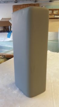
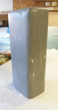
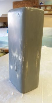
Ok, so I admittedly spent a few hours today on the Oil “Tower” Box, so prepare yourself for a number of pics of it.

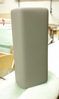
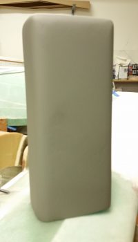
I started out by giving the primed Oil “Tower” Box a very thorough sanding down.

I then hit it with another few coats of primer before heading out to run some errands.
When I returned I again sanded the primer, only this time I wet sanded it.
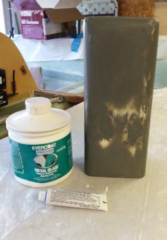
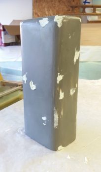
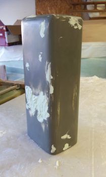
With a solid base of primer in place I then set about to rid myself of the numerous divots I had in the surface of the Oil “Tower” box.  I would be using EverCoat’s Metal Glaze for the aforementioned ridding of divots.
I then slathered up the oil “tower” box with Metal Glaze and let it cure.
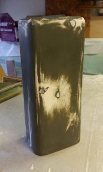
I then took the box outside and knocked down all the high points of the cured Metal Glaze with a hard sanding block.  I then brought it back inside and wet sanded it to get the final feathered finish between filler and pre-existing box surface.

I then shot it with a couple coats of primer one last time.

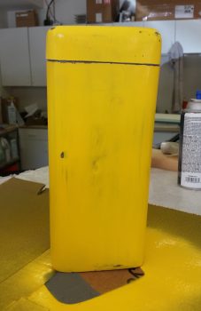
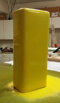
I then very lightly wet sanded the Oil “Tower” box before taking it outside and hitting it with 3 coats of yellow paint.  Tomorrow, this paint will get sanded and then I’ll cut the top of the box off, at which point the separate pieces will then get another 1-2 coats of yellow paint.

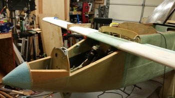
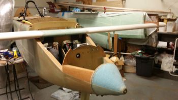
While the yellow paint cured on the Oil “Tower” box I reorganized the fuselage in the shop to allow me to mount the canard.  I then got the canard down off its perch and mounted it to the fuselage.  The mounted canard will provide some data on the final nose build and also facilitate finishing some prerequisite nose tasks before starting in on the nose and canopy builds proper.

Although still a bit tight with just a tad bit of finagling required, I was quite happy with the fit of the canard and the “ease” of getting the canard mounting bolts installed.

I also tested out my new 5/8″ elevator control rod that appropriately enough only has ONE hole for the pitch trim servo arm attach (Just say NO to extra holes!).

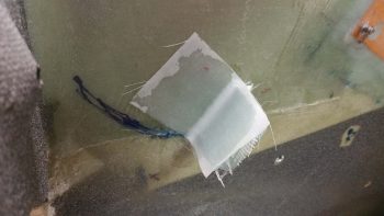
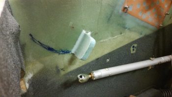
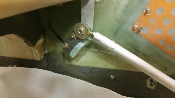
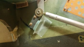
I then rounded up some scrap 3/8″ PVC foam that had a ply of BID glassed to each side and used it as the elevator up-travel control stop.  I whipped up a small amount of flox with fast hardener and also used a small dab of 5-minute glue to secure the control stop to the right fuselage side wall.  As you can see, I used the actual elevator control arm as a sort of jig.

The way I knew the elevator control arm was in the right position was by using the elevator angle template to ensure I was at the max 15° elevator up travel.  I’m actually just a hair lower than I can get the elevator to travel, but any higher up and it starts to contact the canard TE, so this is a good position for the elevator control stop.

Since I had access to the aft side of elevator control up-travel stop, I laid up a ply of BID with the requisite flox fillet.  Tomorrow I’ll layup a ply of BID on the front side and also glass in a small triangular piece perpendicular to the current glassed in tab.

I’m drawing near to being finished with the internal prerequisite tasks for prepping the nose and avionics area for the nose and canopy builds.  I estimate that tomorrow should be the last full day I spend on any prerequisite tasks for the nose and canopy build.


Chapter 13/25 – Showplanes ‘R Us

The title is for my buddy Dave B!

Well, after messing around upstairs a bit when I finally got down to the shop in the early afternoon I was met by an oil crisis . . . as in engine oil was all over the floor and I was in a crisis!  Apparently, with the engine inverted the plug in my crankcase vent gave way and the engine oil exited out onto the large protective drip pan that I have under the engine. But then the oil pooled up on one side, dipping the pan on that side and overflowed the pan edge onto the shop floor in an area about 3′ x 6′.  It just so happens that corner of the shop is where I have a decent amount of wood stored up against the wall.

After nearly an hour of cleaning up the oil, I then started in on the wood by trimming all the oil contaminated parts off.

I then rotated the engine upright and reconfigured the spark plugs and cylinder dehydrator plugs by replacing the top spark plugs with the cylinder dehydrator plugs and firing up the engine dehumidifier.

I had been cleaning and organizing the garage a bit when I discovered where the oil tanker ran aground in my shop, so I went back to that for a bit after I cleaned up all the oil to get the shop a bit more clean and organized.

After some much needed shop cleaning and organizing, I finally used the deck chair pad that I purchased along with my pad of blue memory foam to experiment with different sitting heights.  I think I’ve found what I like which would equate to about a 3″ bottom seat cushion that transitions into a 1-1/2″ to 2″ seat back cushion.  This configuration really gives me a decent seat height for visibility and not feeling like I’m crammed into a low sitting 1950’s mini sports coupe.

I then spent a good 30 minutes dialing in my “final” rudder/brake pedal locations, which I wouldn’t be surprised if they end up moving by 1-2 mounting holes either fore or aft after the rudder cables and brakes are connected and operational.

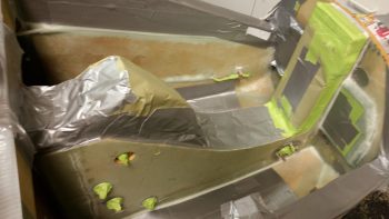
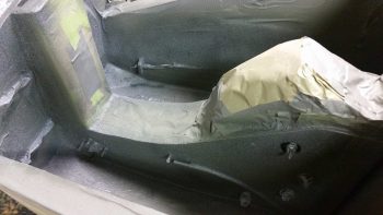
I then removed the rudder/brake pedals and got to work on the laborious task of prepping the front nose area for paint.  It was quite the pain, but I knew if I didn’t do it now that I wouldn’t have an opportunity to do it later so I knocked it out.  Moreover, I wanted to get this nose paint shot and curing overnight.

After about 2 hours I had the nose area taped up and was ready to lay down some paint.

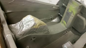
I started with a couple of light coats of gray self-etching primer.

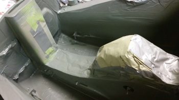
And hit all the exposed spots in the nose area.

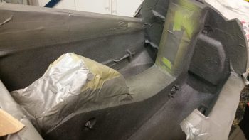
After letting the primer cure for about 45 minutes, I then hit it with a couple coats of the speckled top coat, which is the same trunk paint I used on the nose wheel cover (NB) and avionics bay area.

I let the top coat alone to cure for 30+ minutes and then removed the protective tape and paper.

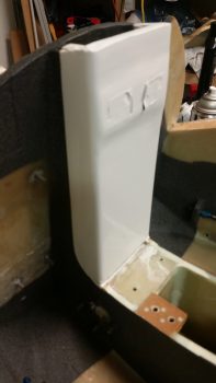
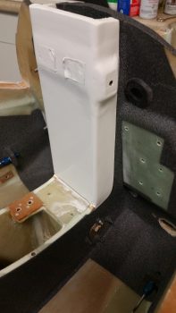
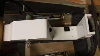
If you were wondering what my white paint job was all about, here it is. As you can see it’s simply a designed accent feature to “cap” the forward end of what is essentially a big white stripe down the middle of the nose compartment.  I figured the white NG30 covers and front mini-bulkhead would lighten up the nose compartment to offset the use of some dark speckled paint.  Plus, I think the dark vs. light contrast just looks snazzy!

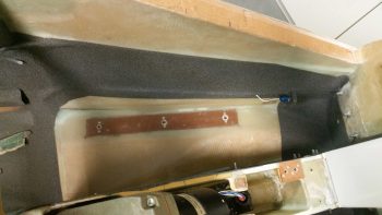
I left a good majority of the floor unpainted for a few reasons.  First, I didn’t want to paint an area that I felt was a higher traffic area.  Next, I did’t want too much dark paint in the nose compartment both from an aspect of visibility (being too dark) and minimizing paint weight where possible.  Lastly, I like to keep a bit of what I consider the cool build features exposed, so analogous to the lower longerons that I left exposed, I could see the dished floor pan and embedded phenolic pedal hardpoint as some good/fun discussion points at fly-ins, etc.

I should also note that I will be adding in a small length of Nylaflow as a cable guide between the bottom of the pedal “S” curve on the front of the pedal assembly to a bolted in AN111-3 hardpoint that is located in the lower sidewall forward of the pedal assembly… on each side of course.  The resulting layups to mount these small cable guides requires that the lower side wall remain clear, for now.  I’ll most likely finish the sidewall paint down to the corner once these cable guides are in place.  I should also note that I left the floor clear on the forward side for the foam/glass work that will be required to mount the oil “tower” storage box as well.

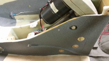
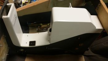
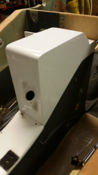
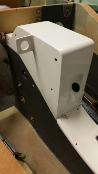
I then finally brought my vision for the nose compartment to life by setting the forward and aft NG30 covers in place.  Granted, the forward NG30 cover is not finished to the mirror shine that the aft cover and forward mini NG30 bulkhead are, but once the wiring, parking brake, brake lines and oil “tower” box are all in place the visibility of this piece will be greatly reduced anyways, so I’m leaving it as the duller looking member of this triad.

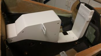
Here’s more of a view from the top that you would most likely see peering down into this compartment with the front nose hatch open.  Note that I will have to obscure (read: destroy) the look of that beautiful top plate of the aft NG30 cover (left in pic below) when I mount the Radenna SkyRadar-DX ADS-B antenna to the NG30 cover.  Alas, I think it will still look clean enough . . .

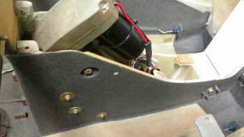
I’ll end this evening’s post with a couple of angled side shots showing the contrast of the white NG30 cover and the dark painted NG30 sides.  This really was the affect I was going for with the white NG30 covers and forward NG30 mini-bulkhead as accent features.  I had originally planned on using no paint at all so the dark paint would not have been visible obviously, but a relatively small amount of paint really does do such a great job evening out all the splotchy build textures and multiple colors assaulting one’s eyes as they peer into these compartments.  I think for a minimal weight penalty it really does the trick nicely (as a point of note, I have not yet pulled up the rather large taped off floor segments in the avionics bay yet, which will expose even more non-painted floor area).

Tomorrow I will press forward with finalizing the nose internals to get ready for the nose and canopy build.  I will most likely finally get around to mounting the canard to facilitate glassing in an elevator control hard stop and finalize the canard top tab mounting hardware configuration & install.


Chapter 3/22/23 – Back at it!

I just returned from my North Carolina sortie late this afternoon.  I of course had to attend to some normal life stuff before getting back into the groove of things.

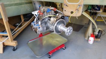
I would like to actually start out by reporting on a couple things I did/noted before I left for NC.  The first is that before I left out I flipped the engine inverted and recharged the cylinder dehydrator plugs with fresh desiccant.  Since I have 4 of the these dehydrator plugs I removed them from the top plug holes on the cylinders and replaced them with standard aircraft spark plugs before flipping the engine upside down. [This is a previous “stock” pic I took of the engine positioned inverted on the engine stand… it’s mislabeled stating that it was inverted only for a few hours vs 5 days].

After replacing the desiccant in the dehydrator plugs I then pulled the 4 standard aircraft plugs on the bottom of each cylinder (of course facing up at this point) and replaced them with the dehydrator plugs.  Since the oil filler cap was facing downward and the top mounted crankcase vent would leak into the Engine Dehumidifier air lines if I tried to attach it to the inverted engine, I just left both unconnected for the duration of my trip.

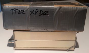
In addition, as I was packing up for taking a load of household stuff down to NC, I found my cardboard mockup of the Trig TT22 transponder.  It became readily apparent why I thought the actual TT22 unit was much smaller than I expected as I realized why when I compared the two.  The dimensions for the TT22 unit are given from the tip of antenna jack to the end of the wire mounting spring clip on the other end.  Clearly the box section of the unit is not included in those dimensions, making it much smaller in real life than my mockup.  Just an observation I had in how there always seems to be some sort of wrinkle in the planning of this stuff for the aircraft build.

So I got back home late this afternoon from NC and immediately kicked off an overdue Seattle Avionics chart data update for the GRT HXr EFIS (I missed the previous one… ).

In addition, the desiccant I left in the oven while I was gone was clearly saturated with moisture and had turned a bright light pink, so I fired up the oven to refresh the desiccant to its desired brilliant blue state.  A while later, after letting it cool a bit, I put it back into a sealed container to use in the Engine Dehumidifier after I flip the engine upright tomorrow.

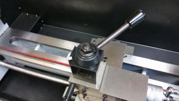
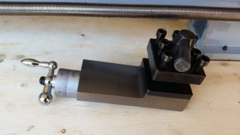
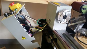
Also upon returning home I found that some packages had arrived, including a digital tachometer and project box (to mount it in) from Ebay for the lathe.  Since I had to make a Home Depot/Lowe’s run I decided to do a quick check of the upcoming tach install to ensure I had all the components I would need on hand…. which I didn’t so I ginned up a list.  While I was at it I spent another 20 minutes mounting the lathe Quick Change Tool Post (QCTP) onto the lathe compound/cross slide/carriage.

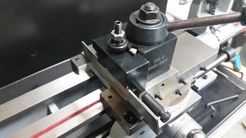
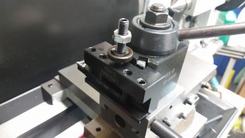
Once the heights of the various lathe turning/cutting tools are dialed in, the QCTP will allow me to swap out tools in literally seconds vs tens of minutes.  Below are examples of a parting (“cut-off”) tool [top] and a turning tool [bottom], each in their respective tool holder [the attached tools are from a cheaper carbide tipped “indexable” tool kit I picked up from Harbor Freight, since it had good reviews…. I’ll use these tools as part of my kit starting out so if/when I break them during initial lathe ops, my cost of learning will be cheaper!].

Late this evening I did some final updates on my nose and canopy build task lists and printed those off in prep for starting back on these builds tomorrow.


Chapter 3/13 – Tooling up…again?!

Knowing that my lathe was getting delivered today and that I needed to sign for it, I started by opening up the shop and got busy wet sanding the very front NG30 mini-bulkhead that I clear coated last night.

After wet sanding it I buffed it out with rubbing compound and then hit it with a couple coats of polish.  It’s not perfect by any means but I think it will look great as a part of the white center NG30 “console”.

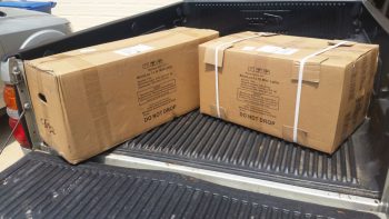
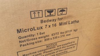
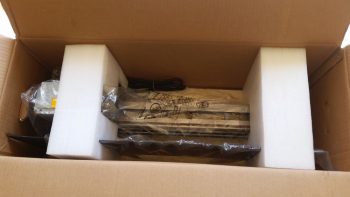
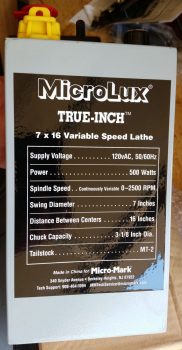
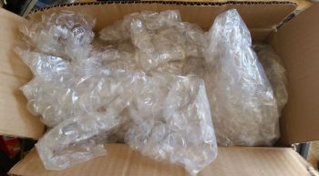
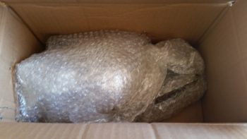
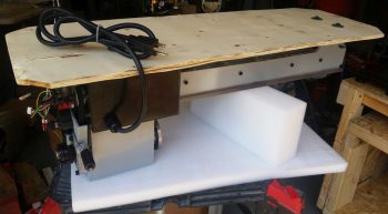
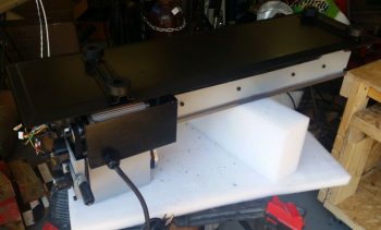
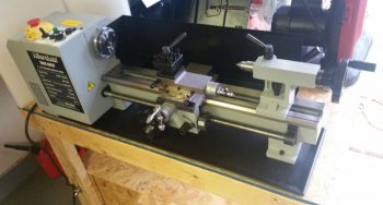
Then the UPS guy showed up with my lathe.  Which came in 2 separate boxes. [I’ll warn you now that the rest of this blog post pertains to the lathe, so if you’re not interested you can shut this down now…. cheers!]

Yep!  It’s a lathe!

Two big benefits of getting this specific lathe was that A) it was actually in stock, and B) the reports on it NOT being delivered in a mangled, unrecognizable container were non-existent.  In fact, the feedback was that it was packed VERY well for shipping (Two boxes vs just one greatly verified that fact).

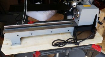
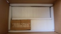
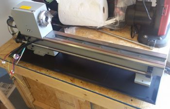
Box #1 contained the main body: the headstock and the bed (aka rails).  It also contained the chip pan.

I then pulled the rather heavy headstock and bed assembly out of box #1, still mounted to its wood shipping mount plate.

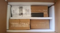
I then opened up Box #2.  Words can’t express how pleased I was with the packing quality of these components.  The foam here was not cheap styrofoam, and the overpacking was just off the charts.

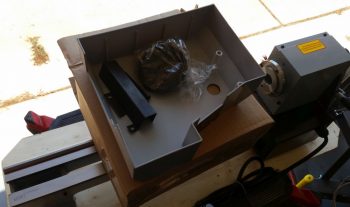
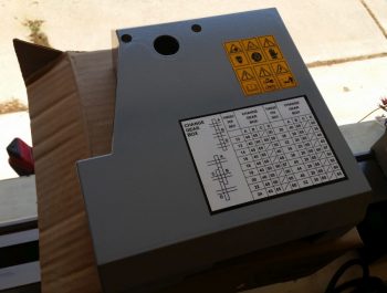
Box #1 of Box #2 was the gear cover that mounts to the left end of the lathe to cover all the gearing on that end.  Now, the motor is a direct belt drive configuration, but the ancillary lead screw drive and threading is gear driven.

Here’s the outside of the left end gear cover.

Box #2 of Box #2 was the electronics box.

The outside of the electronics box is the front of the lathe and the top is the control panel.

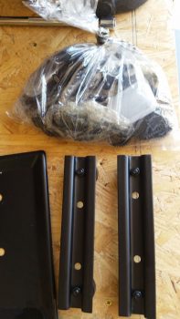
Then there was the odd components: the rubber mounting feet brackets and bag of accessories.

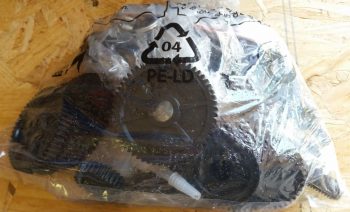
A closeup of all the threading gears in the bag of accessories.  This bag also included all the hardware and handles.

The rear back splash was honestly the only “free’ floating component packed in Box #2.

With all that stuff that came out, and there was still 2 boxes left to go in Box #2.

And again, the overpacking and protection was spot on!

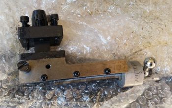
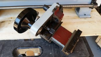
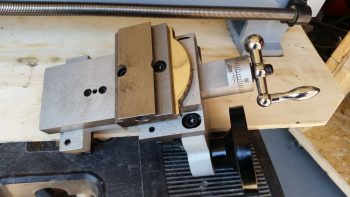
One of the boxes contained the Compound slide with the old style tool holder attached (this will get swapped out for a quick change tool holder).

The top view of the Compound assembly.

Here’s the cross-slide assembly underside.

And the top side of the cross-slide assembly.

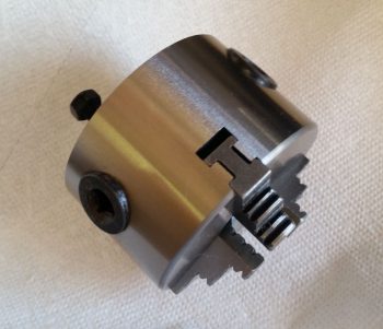
And let’s not forget the 3″ chuck (that I’ll most likely never use).

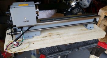
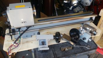
Here we have the headstock, the bed, the tailstock, the compound and cross slide.  I should note that as all these metal parts were unboxed I cleaned them with solvent.

I then flipped the headstock and bed upside down to remove the wood shipping mount plate.

And then mounted the chip bed and feet assemblies.

I then set the lathe assembly in place on the work bench.

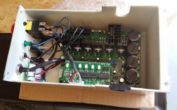
And started wiring up the electronics box.

A closer shot of the electrical wiring getting connected out of the electronics box.

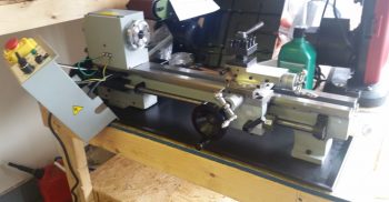
As I was checking the operations manual I ran across a template with the dimensions spelled out to hard mount the lathe to the bench.  I liked this idea much better so I removed the rubber feet and spent well over an hour (my issues, not the machine’s) getting it mounted to the bench.  In the end, I like this configuration MUCH better… a lot more stable.

To see the lathe in action and overview of my latest tooling up, I created a fairly short video:

This will be the last post I make for almost a week as I pack up another load to head down to North Carolina.  For any curious types out there, I should be down in NC by the end of the summer.  After settling in I plan to stop offering up these silly excuses as to why my plane is not finished yet!


Chapter 3/13 – Trimming up Dolly

I actually started this project a couple of days ago and finished it today.  Instead of stringing you along like I normally do, I just decided to show you what I was up to all in one whack!

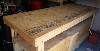
I noted yesterday that my TIG welder was the “Elephant” in the middle of the shop, when in fact a truer statement would be that the fuselage dolly, having served its purpose well, is now the true elephant in the shop.  Not only do I need to trim it down for space, but I need to repurpose it as a portable tool work bench for my upcoming focus on making some bric-a-brac for the plane.

I started by clearing off the top of the fuselage dolly and then giving it a good cleaning.

I then removed all the hardware and wood brackets off the top.

Here’s the last official pic of the fuselage dolly before it got a massive makeover (key some dramatic music from some crazy reality TV show!).

I determined yesterday that I need the top to be 38″ long, while the width will remain a hair over 30″.  After determining the top area that would remain, I started on each end, cut and then removed the top shelf pieces and the underlying support frames.

I then removed the 4 corner slide posts that would get reattached, and then trimmed the remaining overhanging wood support rails from the table top.

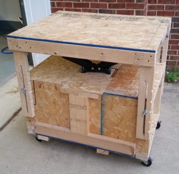
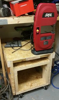
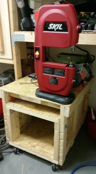
About 2 hours later I ended up with a much shorter version of the fuselage dolly that again, will now be used as a portable work bench that power tools will get mounted to.

I mounted 2 recent acquisitions –the red 9″ Skil band saw and the Harbor Freight bench top combo sanding belt and disc machine– along with my ever faithful bench top grinder that has never really had a home.  Yes, I know that these tools don’t get high marks for being the best in their respective classes, and I’m sure they got beat up a lot in tool high school, but by all accounts they work well enough to do what I’ll need them to and moreover, they were cheap (like me!).

You may have noted there is a spot on the opposite side of the table, which is for a mystery tool that for now we’ll call: Tool X.  It is vitally important that the information as to the type and purpose of this tool not be made public at this time…. especially to Marco! haha!

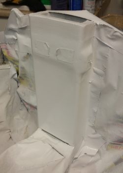
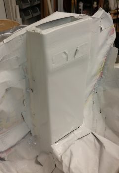
My initial plan for the day was to wet sand and then clear coat the front NG30 mini-bulkhead so that I could have then wet sanded and buffed that out either later this evening or tomorrow, but alas I broke through the topcoat when I was wet sanding and had to repaint those areas with another couple coats of white paint.

Finally, much later in the evening I was able to successfully wet sand the white top coat and then clear coat it with a tack coat and then 2 full coats of clear.  Yes, I understand that these pics probably look exactly the same as the gloss white top coats…. but trust me, THAT’S clear coat on there!

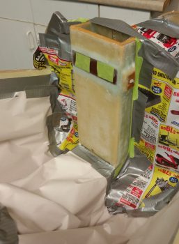
I was remiss in getting a pic of the Oil “tower” box with its surface sanded down, before primer… after nearly an hour’s worth of sanding on the stubborn surface.

I toyed with the idea of using a bit of metal glaze body filler first but then decided I would not only use the primer as a bit of a guide coat per se, but also let it sit for a week to really cure while I’m down on my next trip to North Carolina.  For certain it will need some help in the hole-filling department, especially that crater on the north face, but I determined that it would probably be easier to do after the primer was on, cured and wet sanded.

My build tasks will be minimal tomorrow since I have to get into packing mode (which I was supposed to do today!) to prep my next load out of household goods to haul down to NC.


Chapter 13/22/23 – Painting Goalpost

I started off today making a run down to Harbor Freight for some equipment and tools.  I then headed over to my neighbor’s house for a while since he wanted some male company during their Mother’s Day cookout.

After some great food and beer, and a nice break with my buddy next door, I then spent some time assessing, evaluating and designing the conversion of my fuselage dolly into a bench top tool table on wheels.  I’ll report more on that tomorrow with pics.

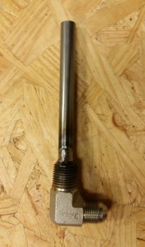
I then had to contend with what had become an elephant in my shop, sitting there in the middle of everything and just getting in the way: my TIG welder. With new TIG torch consumables in hand, I needed to finish up my patch job on the oil heat engine sump fitting’s weld to the standpipe.

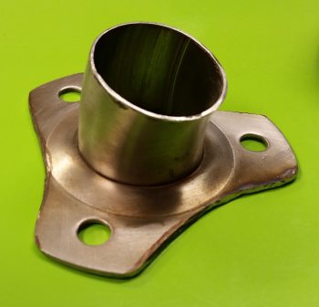
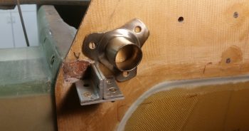
However, when I started clearing off my welding table I ran across my stainless steel upper left firewall pass-thru. I needed to trim it up and instead of setting it aside to do later and forgetting about it –like I did last time– I just spent the 20 minutes [and 3 Dremel disk changes…. that stainless steel is TOUGH!] to get it done.

Here’s a shot of what it looked like before, in case you didn’t remember.

I then mocked it up on the firewall for a quick test fit…. looks good and I think it will work fine.

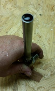
I then welded up the remaining tiny gaps in the oil heat standpipe patch that I had to weld in place when I blew out a centimeter sized hole in the tube sidewall.  After an initial test to ensure there was no leaks –and there was NONE– I then ground down the weld repair to minimize it’s robustness a bit.  [One thing I didn’t show here was that there was a decent blob of solid metal inside the tube as well that I drilled with a large diameter drill bit to remove].

I then did one last test on the oil heat engine sump standpipe to ensure there was no leaking out or from around my welded repair patch.   And there was none…. SUCCESS!

So a few days ago my buddy and fellow Long-EZ builder Dave Berenholtz asked me if I was building a show plane, to which I answered something along the line with, “of course not!”  Well, after my escapades this evening I can understand why he might ask me that. ha! I do definitely have some design ideas for the interior of my aircraft…. not really the cabin area mind you, but more the nose area.  Nothing major, but I am essentially making a white accent stripe down the middle of the NG30 to lighten things up in the somewhat confined and dark spaces of the nose.

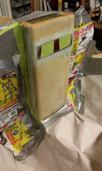
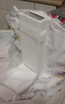
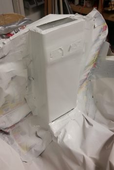
Given that, my last piece of the white center stripe –which I’ll paint first before the tad bit of color (same as nose wheel cover) that I’ll be putting on the sidewalls and NG30 sides– is what I call the goal posts… actually the goal posts existed before I put the plate in on top of it. FYI – the “Goalpost mini bulkhead” is what the original plans called out as F6.

Anyway, this mini-NG30 bulkhead will get painted white, overlapping a bit on the sides. The fancy part is that I taped in a curve at the bottom side to somewhat match the curve on the front edge of the forward NG30 cover (For those of you in the US or know the Progressive “Box” Dude…. it kind of looks like that too me).

I will add that I prepped it with a thin skim coat of micro last night, and then after I sanded that down I hit with a thin skim coat of epoxy before heading to Harbor Frieght.  To reduce the cure time so it would be ready to work on when I returned, I set a heat lamp on it.

Upon returning I lightly sanded the surface and prepped it for primer and paint.

Here’s the “goalpost” bulkhead after a couple of light coats of primer and then 2 standard coats of paint.

Tomorrow, after the top coat cures, I’ll sand it just enough to dull it and then hit it with a couple of coats of clear.

I plan on getting a bunch of internal nose prep work done tomorrow, as well as my fuselage dolly metamorphosis, but I will also be transitioning into move mode since Thursday I’ll be heading back down to North Carolina to deliver a load of household goods.