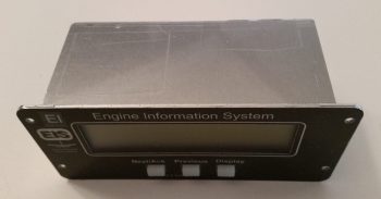
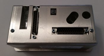
Chapter 22 – EIS Harness galor . . .

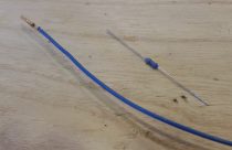
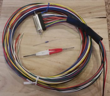
I started out today gathering up my GRT EIS4000 wiring harness, a 300 Ohm 1/4w resistor, and my D-Sub socket removal tool.  My task here was to add a cross connect wire from the EIS4000’s blue 4.8V excitation wire to the engines oil pressure sensor’s EIS signal input lead.  This is required to ensure the ~5V signal strength is maintained at the oil pressure’s input port on the EIS unit.  Physically, it is simply a cross-connect wire from the blue to the orange/black wire in the EIS4000’s wiring harness.

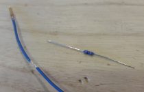
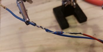
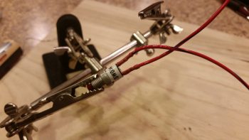
I started off by removing the blue wire from the D-Sub connector, then trimmed about a 1/4″ of the insulation off of it a few inches from the D-Sub socket and then wrapped one of the resistor legs around the exposed wire segment.

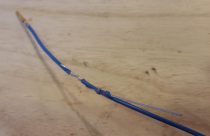
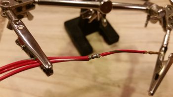
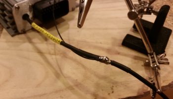
I then soldered the resistor to the exposed wire segment on the blue 4.8V wire.  Next, I soldered a short length of 22 AWG orange/black cross-connect wire to the other leg of the resistor.

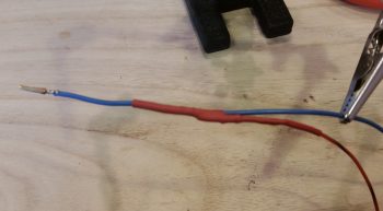
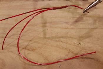
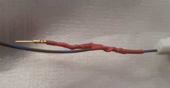
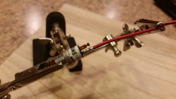
I then trimmed up any protruding sharp edges and enshrined my work in red heat shrink.

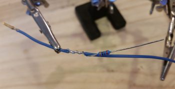
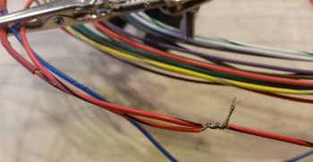
On the EIS4000 oil pressure sensor port’s orange/black lead I then exposed about a 1/4″ of bare wire just as I had done on the blue wire above, only this time it was 4-5″ downstream of where I had tapped into the blue wire.  I then wrapped the stripped end of the cross-connect wire around the bare part of the oil pressure sensor wire….

and soldered the cross-connect wire to the oil pressure sensor wire.

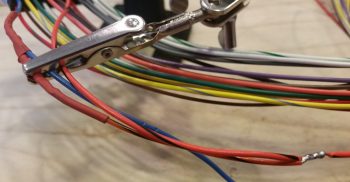
I finished off my task with another round of red heat shrink over the cross-connect/oil pressure sensor wire solder-spliced junction.

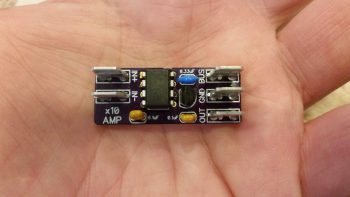
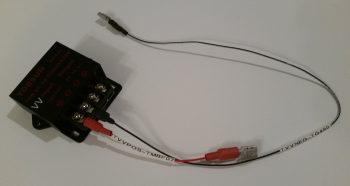
In other news… I finally received my Bob Nuckolls recommended and Eric Page built AD626 Op Amp board (for displaying Electroair Spark Advance on the EFIS via the EIS). Once again Eric did a phenomenal job constructing this board. I really like his concept of using PIDG FastON tabs for connecting wires to the board…. nice & EZ!  Moreover, I’m extremely thankful that we homebuilders have a corroborative means such as the AEC forum to figure this stuff out.  Such an excellent resource.

Although I won’t have any wire labels until Monday, thus keeping me from completely wiring up the AD626 Op Amp Board, I did start prepping the EIS wiring harness with connective wires to connect to this rather diminutive component.  As an aside, the FT-60 fuel flow connects to a 12V+ port on the EIS4000. In addition, the manual specifically states to use this 12V+ port to connect the Fuel Pressure sensor.  Thus, since I have 12V power at the ready (the AD626 Op Amp board uses very little power), I am merely going to tap into the EIS4000’s 12V+ port to drive the AD626 Op Amp as well.

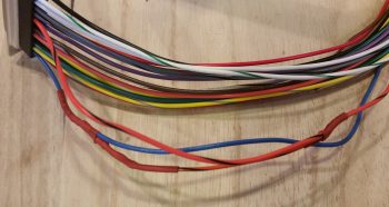
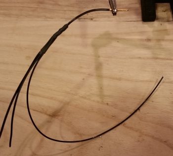
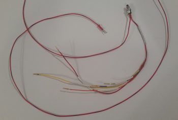
Pictured below are 2 wires connected to the bared 1/4″ section (just like above) of the EIS4000’s 12V+ out power port, making 3 out leads from this one port.  The longer original Red/Blue lead is for the FT-60 Red Cube Fuel Flow Transducer.  The next longer Red/White lead is for the AD626 Op Amp board, while the shortest red lead is for the Fuel Pressure sensor lead.

I then soldered the 2 added power wires to the EIS4000’s 12V+ out lead.

And then added some heat shrink to the solder joint.

I pretty much did the same thing as above for the ground side of the circuit by tying into the EIS4000’s ground wire.

Besides my usual antics of updating associated wiring diagrams, and sending out some email inquires with a little bit of research sprinkled in, I was also able to finish editing a video that I recorded for my buddy Dave Berenholtz.  The video discusses some topics on aircraft electrical wiring.

Again, with cold weather at hand I’ll continue in my electrical-centric mode until it starts getting a bit warmer.


Chapter 18/22 – Panel Indicator Lights

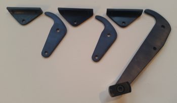
I started off today discussing a variety of issues via email with my buddy Dave Berenholtz, one of which was parts availability for the canopy latch system.  I took the pic below of my Wilhelmson RL-1 rotary canopy latch components to add some clarity to my email and thought I’d include it here.

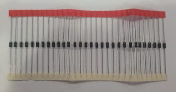
I also thought this string of 1N4007G Diodes that I just got in from Mouser would also make a cool pic and show you guys what they look like in “raw” form.

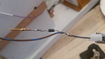
Here’s one of those diodes in action on one of the pigtails I added to 5 of the 9 panel On/Off indicator lights that allows me to tie into switch #4, the Push-to-Test button’s wiring harness.  As I mention in the video (below) that I made to highlight the Push-to-Test button (and freshly wired dimmer) for these lights, I can only hook up 5 of the 9 lights to switch #4 for testing because the other 4 On/Off indicator lights contain closed systems…. where the configuration of the components that those lights report on do not support connecting them to the Push-to-Test circuitry.

The added wire –in the form of a pigtail at first– to each light is nothing more than an alternate power source that provides 12V+ input to each indicator light connected to the Push-to-Test (PTT) circuit.  The power provided by depressing the PTT button (switch #4) then flows to ground out of the other terminal of the light’s connector (via the dimmer switch).

Thus, I’m utilizing the diodes in the PTT circuitry (pigtails) on these lights as a one-way valve, preventing power being inadvertently applied to the other lights when only one has a real valid condition to cause the light to illuminate.  For example, due to the way I’ve constructed the switch #4 wiring harness, if I didn’t employ diodes on each line then when I pulled the parking brake handle, which closes a switch allowing 12V+ power to run to the indicator light, the power would then back-channel through the pigtail (switch #4 wiring harness) and power up the other connected indicator lights.  Obviously that would not be good, and as you can see these diodes prevent that scenario from happening.

Here is the same pigtail as above only covered with red (for indicator 12V+ power) heat shrink.  One thing I should point out is that the connection to these panel On/Off indicator lights for the Push-to-Test circuits utilize D-Sub pins and sockets that themselves will be secured with heat shrink.  I used D-Sub pins and sockets due to the fact over a myriad of configuration changes on the wiring system, I have spare wires terminated with these pins and sockets.  In addition, I have a good number of spare terminated 22 AWG wires of different colors (shown on the switch #4 side of the equation in its mini wiring harness) from included GRT and TCW wiring harnesses.

Just as I did on the panel On/Off indicator lights dimmer switch, I then determined the required wire lengths to the 5 lights that will be connected to switch #4 for the Push-to-Test circuit.  I stripped the ends of these 5 wires of varying lengths and then soldered them all to the lead hanging off one side of switch #4 (the Push-to-Test button).  The lead on the other side of switch #4 goes to 12V+ main bus power and since I didn’t know exactly how long this wire needs to be, I just terminated it with a cheap automotive connector for now. I then labeled the 5 terminated leads (4 pins/1socket) on this harness (I labeled the switch pigtail lead before soldering the harness together).

With my Push-to-Test switch & wiring harness complete, I hooked it up and tested it out.  I was quite pleased at how both the dimmer and the Push-to-Test functions were working.  So pleased in fact, that I decided to make a video, especially since it’s difficult to describe light dimming action, so I figured a video would help show it much better.  I also briefly touch upon the new Engine function display page on the Mini-X that I just recently loaded.

As I keep saying, with the weather as cold as it is, which prevents composite work in the shop, I am focusing on getting a bunch of these small electrical taskers –mainly panel related– knocked out.


Chapter 22 – Paneltronics

Today was forecasted as the warmest day we’ll have for the rest of January, with the remaining temps in the high 40’s at the warmest.  So, besides building my engine this month, I really plan on getting all the electrical stuff that I can do knocked out, plus a few tasks that I can do in a fairly cold shop.

Today was still about cleaning up some panel electronics and getting some tasks crossed off the list. I decided as I started my endeavor to solder up my Pitch Trim power ON/OFF switch for the TCW Safety-Trim system that I would do a video on aircraft electrical wiring that my buddy Dave asked if I might be able to generate.  I still have some editing to do on the video, but will get it posted on YouTube in the next day or so.

First off, in my latest Mouser order I just received 2 new mini-toggle switches with flat bat levers (my preference) for switches #11 (Pitch Trim power) and #12 (Heated Pitot Tube on/off).  Besides having 2 different brands of switches in the row of switches on my center panel column (see pic below), the switches that I replaced were ON-OFF-ON while these new ones are simply ON-OFF.  No need to waste good switch capacity, especially when the switch levers were slightly different.

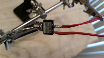
I started off by wiring the 18 AWG E-Bus lead to one side of the switch, then covered the solder joint with red heat shrink.

I then prepped the supposed two 20 AWG Pitch Trim power wires (as listed in the TCW Safety-Trim manual) for soldering, but then when I went to strip them found out they were actually 22 AWG.  No big deal, just a point on how robust Tefzel aircraft wiring is in handling amps and heat.

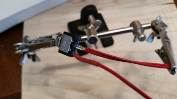
I then soldered the 2 twisted 22 AWG wires to the remaining post on switch 11.  This switch is the “master switch” that provides power to the Pitch Trim system and exists mainly as a safety switch in case there’s a runaway trim situation.

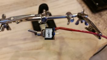
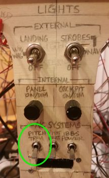
Here’s a shot of switch 11 (code sw011) remounted in the panel mockup with the soldered wires now attached.  I’m waiting to terminate the 18 AWG wire with a FastON connector to then mount to the E-Bus until after my next shipment of wire labels arrive.

I’ve circled switch 11 in the pic below in green.

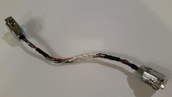
I then pressed forward with my plan to mount both GRT OAT probes forward in the fuselage, specifically in the nose gear wheel well (NB).  I removed and then disassembled the GRT Mini-X wiring harness to slip the gray wire into the mix.  Nicely, I was able to use the original OAT probe wire off the GRT EIS4000 harness that was already terminated with a D-Sub socket at the Mini-X end.

After I inserted the wire and reassembled the D-Sub back shell on the Mini-X side, I realized I should probably grab a shot of my progress.  As I noted above, I’m out of wire labels but had just a long enough piece of blank white wire label heat shrink to hand write the label for this wire…. just so I could get it in and knocked out.

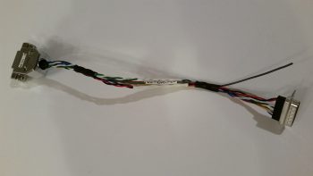
I then terminated the J3 connector side with a D-Sub pin and inserted the wire into the D-Sub connector.  Again, below is a pic of the OAT wire addition task complete, with the J3 side D-Sub jack back shell back in place.

I then reinstalled the Mini-X wiring harness, fired up the panel and checked the OAT settings.  I set the HXr on Celsius, set the Mini-X to Fahrenheit, then toggled the Mini-X setting to have the OAT show on the PFD page.

As I mentioned above, tomorrow will be more electrical system tasks since it’s still fairly cold for shop work.


Chapter 18/22 – Power Busses labeled

I started off this morning reading an email from my buddy Dave in OZ extolling some issues on placing the latch for Jack Wilhelmson’s RL-1 Canopy Rotary Latch system. Dave has too many interfering components, including the left knob on his Garmin GTN650, if he tries to put it in the traditional location just in front of the left side of the instrument panel. Just as a point of note, that was seriously a big primary reason why I went with the GNS480: no left knob except the on/off/vol knob, which is still however my own limiting factor for moving my RL-1 latch up as close to the panel as I’d like.

Well, curiosity got the better of me, so I grabbed my latch and mocked it up…  I was aiming for the plans’ ~4″ in my head and mocked it up quickly, realizing immediately after I took the pic below that the longer lever doesn’t reach forward as I have it in the pic, it only just travels between the 7’ish to maybe 1 O’clock position (as I understand it).
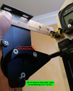
I pulled out the installation manual and had in my notes to move the whole canopy latch shebang 1.4″ forward to allow clearance at the rollover assembly and also for the throttle. Dave’s solution looks to be mounting it mid-strake opening, thus turning it into a center controlled latch with the small catches forward and aft of the main latch, where as obviously both are aft on the plans style latch.

Since I can’t really do what Dave is doing (since Dave is building his Long-EZ to fly around the world, he has no fuselage cutouts into the strakes… the fuselage sidewalls are the interior walls of the fuel tanks), my issue becomes one of tight tolerances and clearances.

Although the cardboard cutout I made as positioned below is ~1.4″ inches forward (F.S. 42.6) of the plans’ position (F.S. 44), allowing clearance for the throttle, this position has the short fat rotary latch knob hitting my GNS480 on/off/vol knob.  Moving it aft about 0.2″ provides clearance for the knobs, but only gives me about 1/4″ clearance from the outboard top edge of my CURRENT WOT throttle position to the robust, square-edged latch cam I note in the pic above (noted as “#1 issue”).
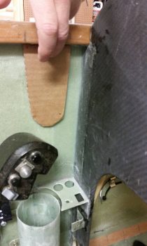
Thus, I provide Wade’s 3-point plan for eaking out just enough room to make this work:

1. Ensure the rotary latch assembly is driven as far outboard up against the sidewall as possible when mounted to better provide clearance between the latch cam (top pic) and the outboard edge of the throttle handle.  BTW, the throttle handle’s outboard edge aligns vertically very closely with the inboard edge of the longeron (if you drew a line or strung a plumb bob and viewed it from top/aft/front), so there is clearance… but I just want more for my poor pinky!  Also, regarding the clearance between throttle and canopy latch, the real issue is only during T/O and climbs at WOT.

2.  I still need to drop the throttle down when I construct the new throttle lever.  With the canopy latch position required to be a hair aft of where I originally wanted it, I may cheat a bit and drive the throttle inboard say 0.1″, and mount it lower (the handle, not the quadrant) the furthest it will go comfortably.
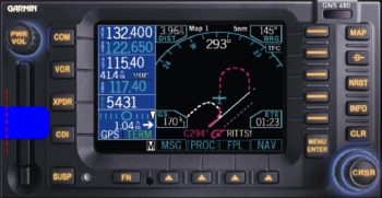
3.  There’s approximately a 3/4″ gap between the front of the rotary latch’s smaller fat knob (depicted blue above) and the GNS480 face when the rotary latch is locked and closed.  Again, this is approximate of course since I don’t know the exact resting position of this knob, but it is close to what I have shown above.  This shorter latch knob will also just barely clear the bottom front edge of the “PWR/VOL” knob. However, since I come in at a slight angle from the right anyway to push the CDI button (XPDR button is inop in my setup), the short fat knob if left alone wouldn’t present a big problem.  But by driving the rotary latch assembly as far outboard as possible AND trimming about 1/8″ off the bottom (outboard) of the knob to reduce it’s overall protrusion into my GNS480 op space, I should have zero issues for any 480 button-pushing tasks that may ensue.

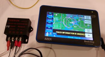
Moving on… After the above shenanigans, I then prepped a small “toy” that I just received in the mail: a 4.0mm OD x 1.7mm ID corded jack to power my Bendix/King AV8OR backup GPS.  I determined a good length for the cord and ended up cutting off about half of it.  I then cut each end of the cord’s 2 conductors and spliced on cheap ring FastON terminals since later I’ll make both a final cord length determination and possibly run GPS and video camera leads into one ring FastON connector –since they’re so small– for both the 5V pos & neg connections.  As you can see below, I then hooked up my new GPS power jack to the terminals on the 12V-to-5V converter.
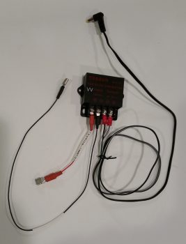
After testing the output of the AV8OR’s original wall mounted charger (5.196V) vs the 5V output coming off my 12V-to-5V converter (5.231V) and determining that the values were very close, I then connected the converter to 12V battery power through a 3A fuse.  I then plugged in my Bendix/King AV8OR GPS unit and immediately saw the amber power in/on LED light up.  The lack of smoke, fire or popping fuse was also a good sign . . . ha!
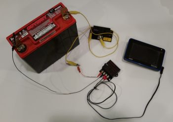
I then pressed the ON button of the AV8OR and it fired right up.
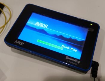
As with most GPS units, it took a few minutes for it to find its bearings, but it then perked up and functioned as normal.  I’m very pleased to be able to have a hard-wired cord to use to power/charge this backup GPS unit without having to use up a cigarette charging port and contend with the bulky AV8OR car power charger.
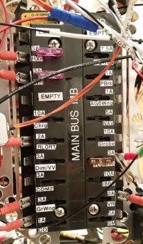
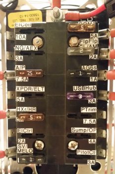
I then finally rolled up my sleeves and took a few hours to label my busses with the appropriate fuse size and a very truncated description that has just enough characters to tell me what the fused item is.  Keep in mind that the labeling of these busses is for operational ease and quick fuse terminal position ID, possible troubleshooting, and/or system design updates.  Although I was aiming for neat, orderly and legible, I am NOT trying to win any beauty contests here, nor win the “Straightest, most-aligned label of the Year” award!

I started off by knocking out the Battery Bus.  Point of note is that after all these pics were taken, I did actually go back with bigger white on black labels for labeling the bus itself with “BATT BUS – BB”
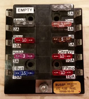
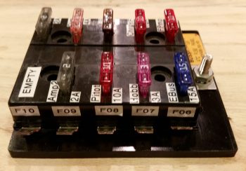
Since I’m focusing on labeling the front of the busses, I thought I’d include a pic of the actual side terminal labels, which is depictive of the other busses as well.
I then knocked out the Main Bus.  If you have good attention to detail, you may note that the main bus has the fuse amp size listed above the fuse with the fuse circuit ID below it.  I already had a bunch of these labeled so I left this scheme in place on the main bus.  Not a huge deal, but I like having the actual fused component ID on the top for better visibility, so I changed it on the E-Bus.
I went out for a bit to buy some groceries and make dinner, then afterwards I knocked out labeling the Endurance bus (E-Bus).  Again, I also made a bigger white on black label and attached it to the center vertical area of the E-Bus just as I did for the Main Bus above.
In closing I have one small, but significant, development to report.  I had a good phone conversation with Marco today and during it I was conveying my frustration with the OAT readout on the MGL clock.  Since the MGL’s degrees Celsius reading is an integer, with no decimal, it makes translating between Fahrenheit and Celsius a pain since the MGL is simply off a degree or two from the HXr EFIS due to this poor equational translation.  If I could, I would merely shut off the OAT display on the MGL and be done with it.

This led to Marco asking if I had 2 GRT OAT probes and I responded I do, one connected to EIS4000 and one connected to the HXr AHRS unit.  Note: this is essentially feeding two OAT data points into the same system, for simple redundancy.  He stated that he has one OAT probe connected to each of his 2 Mini-APs and displays one on Fahrenheit and the other on Celsius.

Ah, ok, this still provides redundancy, but allows each EFIS to control how it wants the OAT displayed.  To be clear, this is most likely possible no matter what or where the actual OAT inputs are located, but the point is that I have a dedicated OAT port on my Mini-X that –after some thought and assessment– I’ve decided now to employ for OAT probe #2 rather than mess around with it back in the D-deck/Turtledeck area.  Since I wasn’t clear on how I was going to mount the aft OAT probe this puts that question to bed since the forwards mount into the nose wheel well (into NB) quite nicely.

Thus, I pulled the OAT wire out of the EIS4000 harness and updated all associated wiring and connector pinout diagrams.

Tomorrow I’ll continue to work miscellaneous electrical taskers, with the rewiring of the seat warming pads –to replace auto wire with aircraft grade Tefzel wire– coming up soon.

 

Chapter 22/23 – Bad Assumptions…

will get you every time!  We all know the saying about assuming, well I “went there!”

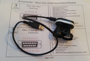
Before I tell you that story of woe, first some successful task completions.  My first order of the day when I went upstairs to work on some even more tweaking of electrical diagrams was to hook up my nose gear auto extension system’s laser altimeter to my PC via the included USB cable to finally configure the settings.

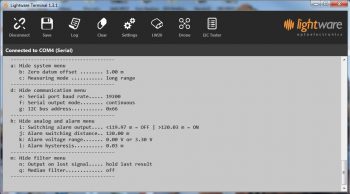
After I downloaded and installed the Lightware terminal program, I then proceeded to set all the operating parameters for the laser altimeter.  Of course that meant going paragraph by paragraph through the manual to make sure I didn’t screw anything up!

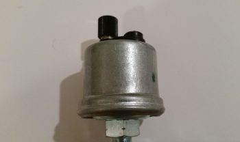
As I was tweaking the electrical diagram for the engine systems and EIS4000, I wanted to investigate further a note I had on my VDO HPS-01 Oil Pressure sensor.  The manual states that the case must be grounded, but the sensor only includes one terminal for the signal wire. As I went back through my notes I had highlighted a myriad of issues builders had had with these VDO sensors . . . mainly in wonky sensor readings caused by poor or no grounds.

Enter rabbit hole!  Well, I wanted to get to the bottom of this since it was a point on my electrical diagram that was cloudy and unknown to me.  I wanted an answer to this riddle so I could press forward with this variable turned into a constant.  After an hour or so of researching my notes, manuals, forum posts (mainly VAF) and other notations, even from canard heavyweights like Marc Zeitlin, I came to the conclusion that my VDO oil pressure sensor, did “in fact,” need a grounding tab attached to the case as spelled out by the EIS4000 manual, et al.

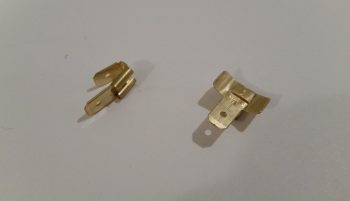
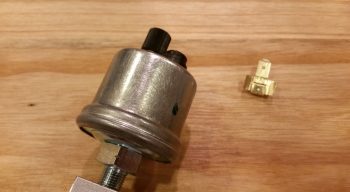
I looked online for these tabs, and after not being able to find a source of supply, I decided to construct one myself from some multi-connnecting Fast-ON tabs I had on hand.  I simply bent the wings of the female connector out to then create curved “wings” that could then be attached to the case of the VDO oil pressure sensor.

Patting myself on the back for my sheer ingeniousness, I then read up on brazing vs. soldering, concluding there that with brazing being generally 5x stronger than soldering, I should “in fact” go that route.  I perfected my expertise by watching a few YouTube videos on brazing, and with my newfound knowledge in hand I ran down to Lowe’s and grabbed some bronze brazing rods.  Ah, my plan was coming to fruition!

I got home, cleaned up both surfaces to be brazed with steel wool and then some wipes with Acetone.

I had let a wood board soak in water while I was gone and used that as the underlayment for my project.  Yes, all ready to go!

And then the “fun” began…. with my portable propane torch I attempted to get this baby red hot.  Well, after not doing that, but inadvertently burning some of the plastic assembly on the top side of the sensor (merely cosmetic) and realizing my best attempts of getting any bit of the brazing material to lay down was a lesson in futility, I called it quits.

Hmmmm?!?!?!

I then decided that since I had a fair bit of surface contact between tab and case, I would try my hand at soldering the tab onto the case.  Again, no joy!  The case seemed to be impervious to any attempts to attach anything to it!  Crazy . . . .

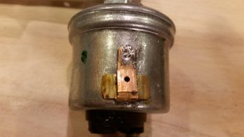
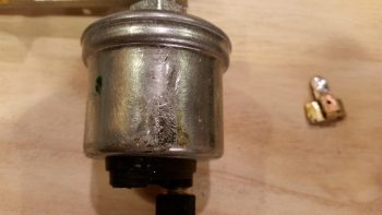
Here’s the sad aftermath of my attempts to attach a grounding tab to the side of my VDO oil pressure sensor.

Now, here’s the kicker.  I did learn a lesson in all this.  After failing miserably above, I went back into research mode.  What was the deal with this VDO sensor?  Did they make others (they do) with a terminal for a ground wire (they do).  Hmmmm?  So I uploaded all my pics, put my notes in my blog to finish in the morning, and then called it quits for the evening.

However, as I was getting ready to head to bed, I was looking through pics of installed VDO oil pressure units in aircraft.  Now, I knew if it was installed straight to the engine case (which is a no-no in itself) that it didn’t need a ground wire since the case was grounded. But I was seeing pics of remotely mounted 1-terminal VDO oil pressure sensors like mine WITHOUT a visible grounding wire!

What gives?!

Thus the need for my ground wire . . . or . . . wait a minute!  Ahhhhhh! I quickly did a continuity test on my engine sensor manifold block and –Voila!– it’s conductive!  I got a solid tone with one probe on one end and the other probe on the VDO oil pressure case at the farthest point I could get from the first probe.

Thus, my ASSUMPTION that the manifold block was a non-conductive aluminum spun me off on a wild goose chase and caused me literally hours of un-needed effort!  Combine that with the note on the GRT EIS4000 diagram that states: “The case of the sensor provides a ground connection for VDO type sensors.”  I had simply allowed the word “case,” combined with all the horror stories and accounts of the requirement to attach a grounding tab lure me down a road that was entirely unnecessary!

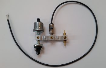
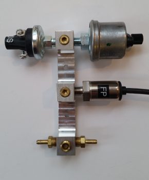
Ok, so here’s a shot (I cleaned up the nasty brazing/soldering marks off the VDO oil pressure sensor with steel wool earlier) of my engine sensor manifold with the sensors attached.  The top left is of course the VDO oil pressure sensor that sends a signal to the EIS4000.  The sensor beneath it is a simple backup oil pressure switch that drives a “Low Oil Pressure” light on the AG6 warning annunciator in case I lose my EFIS, EIS, etc. The sensor with the black cable running out of it is the Fuel Pressure sensor.  On the right you can see 2 brass barbs, one is for the PMag MAP tube and the other tube runs through the firewall into the hellhole where the Electroair and GRT MAP sensors are located.

At this point I’m not sure exactly where or in what orientation the engine sensor manifold block will get mounted, so I included a pic showing it oriented vertically.

I should note that in addition to all the antics above, I spoke with my engine guy up in Winchester, VA.  We scheduled the engine build for the end of next week, so again, I’ll start ramping up for that in earnest early next week.

Tomorrow I plan to get back to the plan, and that is to really make an honest attempt to finish labeling my power busses!


Chapter 22 – Bringing boring back…

Snooze alert!  The stuff you’re about to see is boring …. good heavens, even I’m bored with this stuff!  I tell ya, the one good thing about working seemingly endless hours on the mundane tasks is that it really makes you itch to get back into the shop and sniff epoxy.

I spent over 5 hours yesterday scrubbing & updating every wiring system diagram I have on hand.  I figure that if all goes according to plan that this will be the last winter I have before my first flight to knock out all this nitnoy stuff…. again, much of it that I haven’t gone over in quite a while.

Today I spent a few hours on the phone discussing build topics with another Long-EZ builder, it was a great discussion but it put a sizable dent in my schedule. Why build airplanes when you can TALK about building airplanes?! … ha!

I then did some more cleanup on a few more electrical-related docs before getting down to business.  After attaching about a dozen wiring labels, I then stripped off some of the heat shrink over the solder splice on the Electroair electronic ignition’s control unit ground wire.

I had removed a Deutsch connector a while back and simply soldered the 2 wires together, but now I needed access to that solder joint to splice yet another wire into the mix: the 22AWG lead that will be the negative input (V- In) to the AD626 op amp board for Spark Advance reporting to the EIS.  Again, the signal coming out of the Electroair control unit is too weak so I need to literally amp it up by a gain of 10 so that the GRT EIS can use the strengthened signal to report the Spark Advance to the EFIS screen.

After exposing the original solder splice joint, I then soldered the 22AWG wire into the joint.

I then recovered the new solder splice with some more heat shrink.

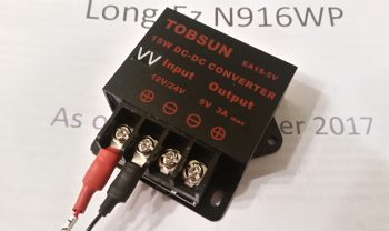
Next, I focused on my 12V-to-5V power converter.  What will it be used for you ask?  Well, in order to use an aft-looking wide angle video camera that I’m going to mount at the top of the headrest, I need to use a 5V power signal to drive it.  In addition, I want to mount and use my Bendix/King AV8OR portable back-up GPS in the lower left corner of the panel, which too uses 5V power.

So I made up, labeled and terminated the power and ground wires for the 12V-to-5V power converter and screwed them in place on the terminals.

I have a power wire jack on order for the BK AV8OR GPS, and I need to acquire some 24AWG wire before proceeding with wiring up the video camera, so below is as far as I’m going to go on the 12V-to-5V power converter for now.

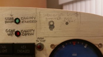
I then assessed and marked the plywood instrument panel mockup to drill a 3/8″ hole for the panel ON/OFF indicator LED lights’ dimmer.

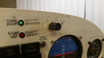
After drilling the hole and cleaning up the sawdust, I then test mounted the dimmer switch and knob…. not bad.

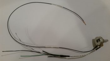
I then got to work on cutting and soldering the panel ON/OFF indicator LED light ground wires to the dimmer switch.

While I was in the vicinity, I also removed the panel ON/OFF indicator LED lights’ Push-to-Test switch and soldered the power leads to it as well.

I then added heat shrink over the soldered leads for protection.
Tomorrow my focus will be on getting the Power Busses labeled, which was part of my tasks today in doing some final determinations on what components go to what tabs on the power busses.  I also updated some ground bus tab and connector pin assignments.

Yes, this stuff can be mundane and boring at times, but it is quite necessary and has proven worthwhile considering the number of small oversights that I keep finding on my diagrams and spreadsheets.  I think nearly all the clerical mistakes have been corrected now, allowing me to start off 2018 with all my electrical system docs and diagrams in order!


Chapter 22 – “Deslumpifier” installed

Today I started out by attaching about a half-dozen preprinted labels to component wires on the instrument panel.  By the end of the evening I had printed out another 2 batches of heat shrink wire labels and attached nearly all of them to their respective wires.  I have to say that printing out and attaching wire labels is definitely an exercise in perseverance and patience, but in the end I know it is way worth the effort.

Again, since the weather is so amazingly cold, I figured now would be a good time to get some really boring administrivia knocked out.  It’s been forever since I inventoried my spreadsheet of 2-character component electrical codes, and since I needed another 3-4 codes for some newly acquired components, I spent well over an hour checking the list, getting rid of old, unused codes, and making up new ones for the new electro-whizzies that I’ve gotten in over the past month or so.  I also printed out the codes and attached them to every electrical component without one, so all is up to date for all the electrical codes on my stuff!

Another can I had been kicking down the road was ID’ing and labeling my Inline Fuses.  It really is the nature of the beast during a build like this for so many components to change as electrical system design and configurations change.  I’ve had “IF00x” listed out for almost all my inline fuses for probably over a year now.  And since my system is much more dialed in and closer to final than a year ago, I figured now was the time to figure out the sequential numbering for all the Inline Fuses.  So I got that list knocked out and updated, then just as I did with the 2-character component codes, I printed out labels for the Inline Fuses and attached them to the appropriate inline fuse.

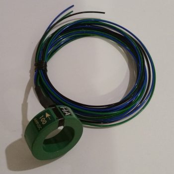
When I checked the mail today I finally received the CS-01 Hall Effect sensor that I ordered from GRT.  As I was configuring the settings on the EIS4000, I did a quick read on how to set up the CS-01.  With it in hand however, today I did some much more thorough research on just how to install the CS-01, including going back and looking at my notes.  I had a few questions, and between the GRT forum and the AEC forum I was able to find the answer…. plus a few other nice-to-know tidbits [Note the “HA” code label].

Along with tweaking the settings for the CS-01 Hall Effect Sensor, I had some other updates I needed to do on the GRT EIS4000.   So I hooked it back up, fired it up, and tweaked some limit configurations and auxiliary port settings.

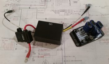
I then worked on constructing some new power and ground cables for the “Deslumpifier” AKA Voltage Slump Eliminator.  Since the power IN for the Deslumpifier needs to be fused, I just picked a location on the Triparagon that allowed me to simply use a robust inline fuse holder with leads as the main power cable.  Right now I’m fusing it with a 7.5A ATC fuse which I think is a good starting point.  To match the massive leads of the inline fuse power cable, I used a black 14AWG lead for the ground cable.

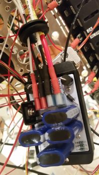
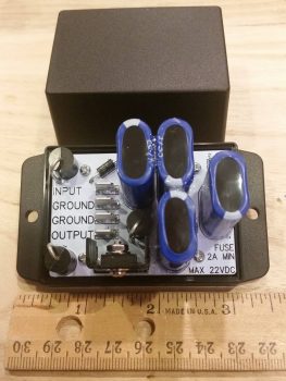
I then cut, labeled and re-terminated the existing power and ground leads to the GNS480 to allow them to be hooked up to the Deslumpifier.  After I finished the GNS480 leads, and before final hookup, I tested the Deslumpifier’s output (to ensure no power surges into the GNS480) and it showed 13.84 volts… definitely good to go.  I then terminated all power and ground leads into the Deslumpifier (note the grommet).

Backtracking just a bit . . . actually before I went final with hooking up the leads above, I cut an initial hole, then widened it into a slot on the end of the Deslumpifier cover where the leads connect onto the board.  After stuffing all the leads into the grommet I had a good idea just how wide the grommet hole/slot needed to be, so I then finalized cutting the appropriate sized slot for wire lead access into the Deslumpifier, including the grommet of course.  I then slid the grommet into the cover’s end slot and mounted the cover onto the Deslumpifier.

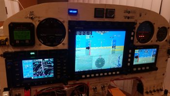
With the wiring looking good on the Deslumpifier, I then powered up the panel, including the GNS480.  Below is a wide angle view of the panel showing that the Deslumpifier works fine in powering the GNS480 in battery mode.  Much later on I’ll conduct Phase II testing which will be during actual engine start to see if the Deslumpifier will keep the GNS480 from rebooting.

I have to say that although there was a lot of mundane work that took place today, it was quite productive.  Tomorrow I’ll continue working on my instrument panel electrical system to-do list.


Chapter 22 – “Deslumpifier”

Alas, in light of the amazingly cold wx we are currently experiencing on the eastern seaboard of the United States, I’ve continued my quest to cross to-do items off my list, whether it is as banal in nature as simply ordering parts.

One such part I recently ordered was my instrument panel eyeball vent to allow me to focus heated air towards the upper part of me during cold flights.  I can tell you that right now that sounds like an especially good feature to have!  This Aveo eyeball vent was actually a bit tricky to decide which version to buy.  At first I was leaning towards anodized silver, even took a small poll.  But after getting everyones’ input and then spending a bit of time looking at both panel pics online and at my own panel, black just seemed the right way to go.  I’m sure in a week I’ll want silver again… argh!

I also received my “Deslumpifier” from electronics guru Eric Page.  He did a great job and his Voltage Slump Eliminator construction looks very professional.  It’s not too obtrusive in size and will add a great feature to my panel by allowing me to simply enter an entire flight plan into my GNS480 GPS navigator –on battery power and thus stress free regarding time (e.g. NOT sitting there burning mucho dinero in the form of 100LL)– before I then power up the engine whilst leaving the GNS480 on.  Good times!

After checking out the “Deslumpifier” I then spent well over an hour updating my engine management system and panel power electrical system diagrams, as well as creating a sheet to cleanly annotate all my current GRT EIS4000 configuration settings.
Another nice little surprise at the very beginning of 2018 was a text I received from Marco pointing out an announcement on Grand Rapid Technologies’ website.  They are now offering the special features package (EIS data display, Bluetooth and ADS-B display) for free on their Mini-X and Mini-AP EFISs.  Well, it ended up that I didn’t qualify for the “free” package, but I found out that I could get it at a greatly reduced price when I ordered my last GRT engine sensor: the Hall Affect Amp sensor.

Since I have Bluetooth and ADS-B on my HXr, I wasn’t concerned about those displaying on my Mini-X.  However, I did really want the capability to display engine data on my Mini-X in case my HXr EFIS display died inflight, so I pulled the trigger and ordered the software.

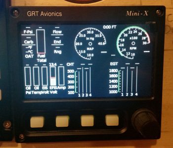
What I didn’t realize was how well laid out the Mini-X engine data display would look (IMO). A few hours after pulling the trigger on the software, I received an email from GRT and was able to update my Mini-X to display engine data.  I have to say that I’m really pleased with how it looks (of course, again, these pics don’t do it any justice!).

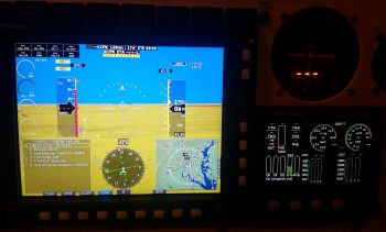
Here’s a wider angle view with the checklist displayed in the lower left inset on the HXr.  I did this to simply show that if I was messing about with a checklist, or had a full screen map or approach chart displayed, that with two button clicks I can very easily bring up the Mini-X engine data screen.  So, not only is it a great backup feature to the HXr, but it clearly offers a lot of flexibility to provide flight-centric information in a variety of ways.

Tomorrow should be another electrical tasker day in that I’ll most likely be doing a lot of wire & component labeling, and attempting to finish up so much of the small electrical items on my to-do list, nearly all of which are currently panel-related.


Chapter 22 – Programming EIS

The last few days has once again been ones of digging into my various engine, engine components and engine sensor manuals both for research and education on the operating limits of each item that will be tracked by the GRT EIS4000 Engine Information System.

As many of you are probably aware, GRT’s EIS Engine Information System was the first product produced by GRT back in 1991 as a result of GRT founder Greg Toman’s search for an automated engine management system for a 2-stroke ultralight engine.  Since he couldn’t find one, he simply built one!  How’s that for the spirit of homebuilt aircraft?

Barring some sideline and unexpected maintenance issues on my truck, today I was able to get both the initial and secondary (more refined) engine sensor upper and lower limits configured into the EIS unit.

Additionally, Nick Ugolini was kind enough to share his EIS4000 wiring configuration diagram with me as well, which served as an excellent qualitative crosscheck on my configuration. Moreover, my decision to mount the EIS4000 control head in the GIB headrest (i.e. “D-Deck” or “Turtleneck”) was based on Nick’s configuration that he shared on his blog (admittedly, in my ignorance at the time I didn’t think it was best to mount the unit so far aft… but it didn’t take long to realize that it was a great idea).

You might be asking how exactly this EIS control unit mounted in the GIB headrest displays engine data on the panel EFISs.  It’s actually very simple in that it relies on one 22AWG wire RS232 serial connection between the EIS4000 and the panel mounted HXr and Mini-X EFISs.

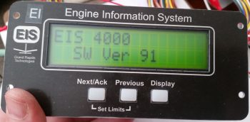
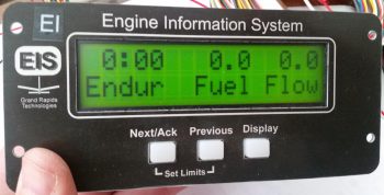
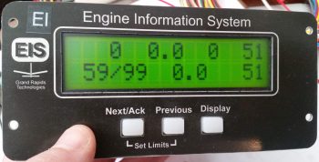
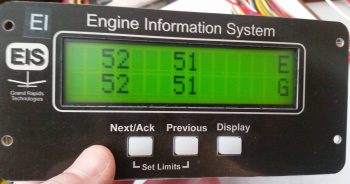
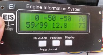
Besides just getting the unit powered up, as you can see in the pics I was able to get some “stick time” on navigating through the EIS4000’s menu pages and getting the initial settings configured.  Also, by assessing the configurations on my AUX ports I was able to play the shell game on paper and reassign 3 of the engine sensor connections with newly associated AUX ports which allowed me to avoid major re-configurations of EIS menu items.

Tomorrow I have some more digging around in the manuals for some “final” verifications on some of my upper and lower limits, such as the ECi IOX-340S’s EGT and CHT numbers.  I’ll also continue prepping for the engine build and knocking out panel wiring tasks.


Chapter 22 – Engine Info System

The weather here is VERY cold, dipping down to ~10° F (-12° C).  So NO shop work when it’s that cold.

On the good news side of things . . .  I got an email from Eric Page, the friendly neighborhood electronics guru off the AEC forum.  He has finished my one-off “Deslumpifiier” that should allow me start my engine with my GNS480 already turned on & flight-plan loaded.  Eric also just sent the completed circuit board up to Alec in Canada for chip coding the onboard 4-into-1 video camera signal processing unit that will feed my GRT EFIS video inset view capability.  This video signal combiner component will end up being about a 6-7 month long collaborative effort by the time I get it into my hands, so again, I’m glad to be getting the more esoteric instrument/electrical requirements through the queue before the real avionics install takes place.

In addition, Eric is close to finishing the tiny circuit board that will have the Bob Nuckolls’ recommended AD626 op amp chip mounted onto it, which will crisply increase the Electroair spark advance signal x10 to allow a very granular input into the GRT EIS box for displaying realtime Electroair electronic ignition spark advance data on my EFIS screen.

Moreover, since it’s currently so cold, today I started working on finalizing my engine info system installation requirements and EIS wiring harness prep.  The bottom line here is that I really need to dig into the manual on my GRT EIS4000 unit to get much smarter on it, both from the installation and wiring standpoint, and the operational integration with the GRT EFISs.

So I’ve been confirming all of the connections for the EIS input sensors, and taking a good inventory of each sensor to confirm what will be plugged into each specific port. I’ve already rewickered and refined some resistor placement requirements, and am confirming literally every configuration –both physically and software-wise– for each connection.

In the next day or so I also plan on doing a bunch more cleanup and labeling on my instrument panel wiring as well, as well as braving the cold shop for some metal work to physically mount the AHARS unit to the Triparagon top cross shelf . . . and figure out my bracket/cable attach points for the 3 heat/air levers.

Over the next few days, I’ll also start gathering all my engine accessories and hardware in prep for my mid-January engine build.  I also need to do as much reading as possible regarding the engine build to get much smarter in that area too.