Chapter 22 – Fake it ’til you make it!

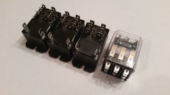
With the weather still not up to par for flying on the days I’ve been available, I’ve been working to get more stuff in the coffers for the eventual final push on this build.  I received an order from Mouser with everything but the Laser Altimeter that I’ll need to implement Marc Zeitlin’s new nose gear system AEX mod, combined with Jack Wilhelmson’s original emergency backup battery feature.  After sorting through a myriad of revisions on the melded, morphed version that falls between Marc’s new system with Jack’s old system, I think the new AEX with battery backup and emergency extend is about the best version it can be.

There are some tradeoffs of course with this new system, and some of that will be in weight.  Although I guesstimate it’s not huge, I’m thinking this new system will be a bit heavier with the required laser altimeter and beefy relays in the mix.  To offset some of the added weight effect, I’m mounting these new monster relays in an enclosed box on the left, aft side of the Napster bulkhead.  That should help a tad with moving the CG ever so slightly forward.

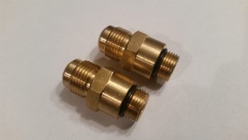
Speaking of weight, I also received two new brass fittings for the oil pump from Buly.  We actually talked a couple of weeks ago and he said he was going to ship them out, but understandably got sidetracked with the sale of his Cozy.  Sad to see him sell it… yet another one of the Ol’ Guard out of the game.

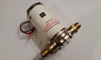
Obviously these fittings are somewhat unique, thus the reason Buly sent them to me rather than just have me order some off of ACS.  Nick Ugolini did recommend that I acquire fittings for 5/8″ tubing, but Buly had these 1/2″ fittings at the ready, and I figured 1/2″ will do just fine.   Maybe these will save a bit on weight with a little less oil coursing through the heating system lines.  Below you can see that I test fitted these new fittings on the oil pump.  Since these brutes are brass, they of course are significantly heavier than if they were aluminum.  But hey, they fit, are in hand and will allow me to have heat in my airplane!

Since I also got a rather sizable ACS order in as well, I decided it was time to take a break from my logistical duties and knock out something that I had started quite a number of months ago.  I had already spent quite a few hours at the beginning of the week logging a bunch of purchases in my tracking spreadsheet . . . and I’m talking stuff from last August, so I wanted to get a bit organized.  My goal before the weather gets warmer, when I can start back on doing some low cost (read: sans high heater settings) layups is to get my recent flurry of research, documentation and instruction manuals put away in my build HQ area (my living room!).  I also spent a good half-hour today doing a cursory cleanup of the shop, but another hour is in order before it will be ready for production again.

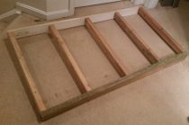
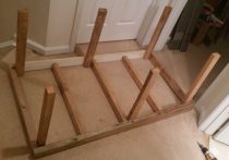
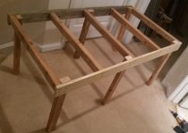
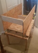
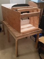
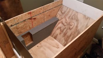
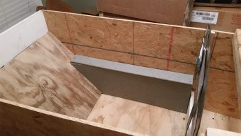
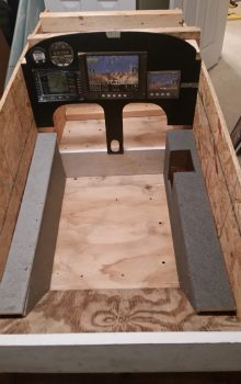
Ok, so my latest mini project was to assemble a bunch of pieces of wood that I cut late last summer to create a cockpit mockup & simulator to allow me test the ergonomics, placement, switchology and operation of my avionics and instruments.  This harks back to my original fuselage mock-up to check for how the plane would feel in its stock dimensions (remember, I widened the cockpit 1.4″).  Now, this version will enable me to mount all my current avionics, plan for new ones, and give me a really close estimate on final wiring requirements for all my panel components.  This latter reason is why I made this cockpit simulator to allow for the installation of the Triparagon.

When the Triparagon is installed I’ll wire up the panel and fire up the components not only to do a good ops check on them, but also to configure them in the panel.  Also, this cockpit mockup will also allow me to finalize any wiring required on the Triparagon.

You may note looking at the pics above that the wood looks a little ratty and non-uniform, and you’d be right!  So far, this entire mockup has been made of completely scrap wood.

Below you can see the right side armrest.  Since I won’t be mounting my second Infinity control stick into the actual airplane, it will get mounted here (although I probably won’t wire it up) into the right side armrest.

On the left side I’ll use the cockpit mockup to figure out exactly where the throttle will get mounted, and how everything else will be configured on the armrest.  You may note the different gray colors of the two armrests, which is me using these as paint color swatches to help me decide the color (or colors!) of my interior cockpit paint.

I’m accomplishing this cockpit simulator mockup construction in 6 phases, and right now I just finished Phase IV.  Phase V will be cutting and installing the avionics in the instrument panel, and Phase VI will be configuring the two separate armrests with the control stick and throttle.

As you can see, once I get this guy up and running, I’ll be able to test out different component and switch locations no matter what’s going on with the actual cockpit.  In addition, this mockup will really come in handy while I’m sanding away on my Long-EZ in prepping it for paint, all the while ensuring that my eletro-whizzies remain dust free!

As you can see, I’m slowly moving towards getting back onto the build.  I do need to really try to knock out this Instrument rating though, although the pace of instruction is very much glacial at the moment!


Chapter 22 – Success!

I got word this morning that my IFR training is back on (there was an issue with my FBO and Part 141 training… all clear now).

In the mean time, I had two separate phone calls today with Rich at Aircraft Extras, Inc. to finally get these AG6 warning annunciators programmed!  After following some instructions in an email that didn’t work (my fault, I entered a data field incorrectly) I called Rich.  He talked me through some steps and helped me understand a couple of the data fields well enough that I got off the phone to tackle it all again.  Well, the umpteenth time is a charm because it worked!!!  Finally!  So I spent the next 6 hours programming and documenting every parameter for each warning screen.  I then did an operational check on each alarm screen by inputting the amount of voltage that it needed to see to kick off the alarm. Thus, now each alarm screen works exactly as it should… (yeah!)

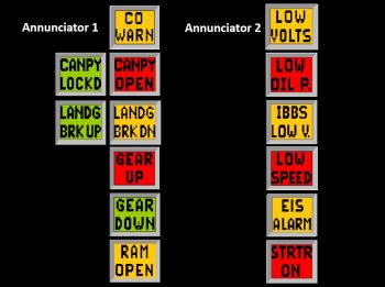
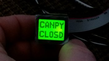
It was a bit tough there for a while on getting these AG6s programmed, but I’m really glad I stuck to the plan for using them.  I can now say that all my major warning annunciations (non-EFIS) are good to go!  One other thing I’ll point out on my AG6 configuration is that on almost all of them I’ve turned off the “Green OK” screen so that I get just the warning screen & only when it alarms.  Clearly, on the canopy, landing brake and nose gear I wanted positive feedback of what was going on with these components.  I’ll also point out that only those issues that would result in an immediate safety of flight issue, damage to the aircraft/engine, or fire are denoted with a red color.  The amber alarms screens show up clearly visible and are an attention getter as well, but I wanted the really bad stuff (obviously, my opinion here) depicted with red.  Finally, I’ll note that the green screens only come alive when the action they represent has been 100% completed.  For the canopy, note that it doesn’t say “Canopy Closed,” but rather “CANOPY LOCKED.”  Same for the landing brake being stowed away and the nose gear extended all the way down.  I actually had a screen stating “gear locked” (since it solved my double gear up/down alarm entry … see below), but after a bit of thinking I decided that I wanted to denote “GEAR DOWN” since to me that communicates more succinctly where the gear is compared to “GEAR LOCKED”.

Moreover, Marc Zeitlin just released his new version of the nose gear automatic extension system (AEX) which streamlined the signal output from the nose gear system with a single wire to each nose gear status indicator light.  What I had to take into account however was that with these one wire outputs it meant one input for the respective gear up and gear down signals.   This meant I had to parse out the normally paired GEAR UP and GEAR DOWN warning screens and put them on separate inputs.  Well, the way the AG6 works is that each alarm has a specific screen code, and the screen code can only be used once in the system since it points all the data to that code.  Well, luckily I communicated what I wanted and Rich talked me through how to “trick the system” by using all the descriptive parameters of the GEAR UP/GEAR DOWN reference number under another unique alarm code (I overwrote the vacuum pump alarm code since I definitely will not be installing one of those in my plane).  With two separate GEAR UP/GEAR DOWN alarms on Annunciator #1, all I had to do (yeah, right!) was turn off the alarm screen (red or green) that I didn’t want to see for each separate GEAR UP/DOWN alarm.

[As a point of note, there were 2 EZ workarounds for the above issue even if Rich hadn’t helped me out.  As I mentioned before, I could have used “GEAR LOCKED” which is a different screen number.  Also, I could have programmed one gear condition on AG6 #1 and the other on AG6 #2, although I did want my final gear positions annunciations in the same place… ALTHOUGH, to further convolute this: my “GEAR UP TRANSIT” and “GEAR DN TRANSIT” indicator lights (not AG6) will not be colocated on the panel so that peripheral vision and color tell me gear moving up or gear moving down … nuff said!]

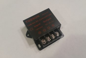
Ok, speaking of Marc Zeitlin’s new AEX, I’m starting to actually receive my component orders to implement that system.  I have yet to order the actual Laser Altimeter, but pretty much everything else is on its way.  Below is the 12V-to-5V converter that I just got that is needed to drive the 5V laser altimeter.  I wasn’t sure which one to get so I just bought the same exact one that Marc has since his system is working.  Hey, if it works, don’t mess with success . . .  right?!

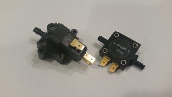
The other components I got in (as if I didn’t have enough of these things!) were 2 different airspeed switches.  The one to the left is a Normally Closed airspeed switch and used to sense when the aircraft is less than 90 KIAS.  The one to the right is a Normally Open airspeed switch that senses when the aircraft is traveling 40 knots or faster.  These will be installed in series so both parameters must hold true for the AEX to function (along with the throttle being retarded to <10% power and the laser altimeter reading less than approximately 350 ft AGL).

Marco had a question on my last blog post regarding Marc Z’s system that I wanted to clear up here.  Here’s Marco’s question:

“What happens if all those [AEX] conditions are met and the gear auto-deploys, then you find yourself a little low on the glide path, and add more than 10% power to correct just before you land? Will the landing gear go back up? Or does it stay down after deployment?”


This is an excellent point, and I should have clarified this in my last post.  The answer is NO, the gear will not go back up because the AEX circuit latches.  Only by cycling the gear switch all the way down and back up will it then raise the nose gear on the command of the pilot to very specifically override the AEX system.  Otherwise, the AEX will keep the gear deployed until the pilot either lands the plane or cycles the gear switch toggle to intentional raise the gear.  I’m glad Marco asked this question so I could clarify this point!

Depending on weather my Instrument training schedule is up in the air.  As for the build, as time allows I have about 4-5 electrical system tasks I want to finish up.  Then I plan on seriously getting back to some glassing, including (don’t laugh!) . . . the wheel pants!

Chapter 22 – “Early upgrades” . . .

One good thing about not getting this plane built on schedule is that it allows for me to implement really good upgrade mods that would normally mean downtime & increased complexity on a flying bird.  In other words, I can take just a scant bit of extra time and roll these new mods into the build plan in whatever area before I ever start in that specific endeavor.  Two such mods that I’ll discuss below are the electric nose gear system and the heating system.

First off, I finally did a bit of research and decided on the style of latch I wanted for my oil dipstick access door on my cowling.  I like the way the one below operates so I picked one up from a guy off of Ebay.  For those curious it’s a Hartwell H2868-1.  I like this specific version since most of the ones that are this style simply have a large square plate with a hole in each corner for mounting.  With the wings of this “H” style it will allow me to bend those just a hair to match any curvature I may have on the oil dipstick access door, which in turn, matches the curvature of the upper engine cowling.  In addition, the main reason I wanted a latch-for-the-hatch is to preclude the complexity and pain of having to use a screwdriver to undo any number of CamLocs just to check the oil!  Plus, as with everything we do, I simply think it looks cool… ha!

I don’t normally include this type of stuff on my blog, but since the use of my laptop DIRECTLY impacts my airplane building I thought I’d make an exception this time.  So my MacBook cord finally gave up the ghost.  No worries, I’ll just pop down to the store sez me to myself and pick up another one . . . how expensive can they be?  Well!!! $78 is how expensive they can be.  Sorry, not gonna happen.  Thus, I fired up the soldering iron and soldered what few molecules of the outer shielding I could find, built a bit of a solder bridge (that’s always fun!) and slapped some heat shrink on it.  And Voila!  Works like a champ!

Now, back to real business.

My build buddies apparently understand that I like bright shiny objects and will take off after them with aplomb if any catch my fancy.  Well, Dave Berenholtz from OZ obviously understands this too well and sent an email asking me if I was aware of what Marc Zeitlin was cooking up in his evil lair.  Apparently Marc was dissatisfied with the standard operations of the Automatic Extension (AEX) feature of Jack Wilhelmson’s EZNoseLift electric nose gear system.  The AEX simply provides an automatic feature of retracting the nose gear after takeoff once the airspeed is above 90 knots, and conversely, will extend the nose gear if the airspeed is less than 90 knots.  Short and sweet.

Well, Marc undertook about a year-long project to refine the AEX system, not just for Jack’s system, but any aircraft actuator-centric system (I’ll note for clarity that in Marc’s quest, apparently the “X” got lopped off the end of “AEX” and now it’s just the AE system). IMO, Marc’s system is fantastic in that by adding another airspeed switch, a throttle “microswitch,” and a laser altimeter, it provides a comprehensive set of parameters that must all be true for the Auto Extend to activate and deploy the nose landing gear:

1: Throttle less than 10% open
2. Speed greater than 40 knots (user programmable)
3. Speed less than 90 knots (user programmable)
4. Altitude at or below 350 ft. AGL

Ok!  Wow, this is truly fantastic news for us Canardians!  I printed out Marc’s description of the system and the electrical diagram and got to work since I wanted to assess how this would integrate into my system.
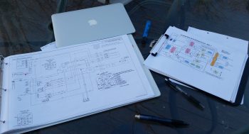
Initially, this all seemed too good to be true!  Where was the catch?  Well, as always seems to be the case there were two specific problems with this new system: the first in relation to my build and the other, a general operational requirement that I desired, which was offered in Jack’s original system but removed in Marc’s modification.

First, the operational requirement:  Marc’s version offers no backup battery capability since Marc personally uses the ratchet drive backup system to extend the gear in case of an electrical failure.  Jack sells his EZNoseLift systems with the option of the mechanical ratchet drive backup -OR- a small 1.2A backup battery that will lower the gear sans ship’s power if the electrical system fails.  Hmmm….  Since I have the backup battery, this was not a good thing in regards to my system.

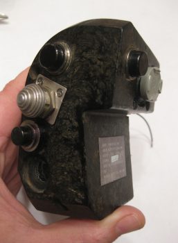
Next, as for the integration into my build?  Marc’s version requires a 3PDT switch to control the gear up & down. My already terminated and installed throttle-mounted SPDT nose gear switch is in the “done” column and is perfect for driving Jack’s EZNoseLift system. Moreover, since this is an F-15 throttle handle, how this rare switch is mounted and its metal hat switch form factor make it very difficult to just pull, plug and replace with another switch.  Moreover, I really have to say that I love my throttle handle just the way I’ve now configured it!  On the pic of my throttle handle below you can see (mid-side handle) the stepped-hat nose gear up/down switch.
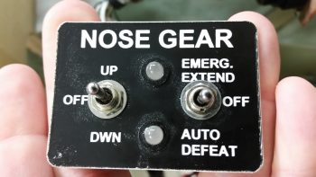
Also, one thing was clear as I stared down this road of integrating the new parts of Marc’s upgraded system while keeping the best part of Jack’s current system, and that was I really needed to truly understand and have comprehensive knowledge of how both these systems worked.  To be honest, with so many versions of Jack’s system out there, I wasn’t even sure what my switch panel looked like!  I went down to the shop and snapped a pic of the switch panel face . . .
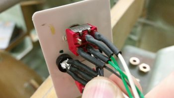
. . .  and the actual wiring of the switches on the backside of the panel in order to identify the correct switches and wiring circuits.
After pondering my gear switch issue for about a day, out of the blue I had a Eureka moment: Duh! just swap out Marc’s required 3PDT switch with a 3PDT relay… right? Problem solved.  Uh, but wait a minute sports fans.  With this being a CANARD gear switch, a problem is presented in simply swapping a switch out with a relay since there’s that pesky “-OFF-” position on our gear switch that doesn’t translate over to a “middle position” between N.O. and N.C. on a relay.  Obviously, on canards we don’t simply use a binary, all-the-way up or down gear position (except for TOs/landings), but use the gear switch to position the nose in a myriad of heights off the ground when parked. Thus, my requirement was to be able to hit the nose gear up/down position, have it run up/down for a few seconds and then move the switch to the “OFF” position to stop the gear from moving any forward.  Again, with most aircraft you simply have an up or down gear position, but we Canardians apparently like to be eccentric! 

I was at the juncture of simply knowing that I wanted to replace Marc’s required 3PDT switch with a relay that I could then subsequently control with my throttle mounted SPDT switch. But how?  Not smart enough in the ways of electrons, I posted my dilemma onto the AeroElectric Connection forum.  Within an hour Charlie England started off his response with a question that gave me my answer: “How about 2 separate 3 pole relays?” Yes, one relay would control up and the other down.  When my throttle-mounted switch was in the middle OFF position, neither relay would be powered on to do any action so the system would be “at rest” . . . or OFF.  I had found my middle position!

[Just as a point of note, since Marc’s 3PDT switch positions were wired to create 2-N.C. states and 1-N.O. state in the up position, and opposite in the down position, it allowed me in the end to only need one DPDT relay and one SPDT relay to replace the 3PDT switch.]

With the switch issue taken care of, now it was time to tackle probably the biggest electrical challenge I’ve ever faced.  I had asked Marc & Jack, et al, on the Cozy forum if there was a way to wire back in the 1.2A backup battery into Marc’s design to provide a means of getting the gear down if a total electrical failure were to happen.  I had some back and forth on a type-of-relay question I had, but nothing on the backup battery except an expressed desire by some to see that “put back into the system.”  With no real response, and having one solved problem (the new AEX system) creating a new problem (no backup emergency gear extend feature), I figured it was time for the proverbial: “Well, if’n you want somethin’ done yer gonna hafta do it yurself!” (Said in Ken Curtis’ Festus voice from “Gunsmoke”).

I spent a day and a half deconstructing both Marc and Jack’s respective systems, and then ala “Tony Stark” (without the flare, billions of dollars, Hollywood CGI or Jarvis) I melded the backup battery feature from Jack’s system into Marc’s new design. Thus, after chasing imaginary electrons around on paper over a couple of days I was finally able to meld the backup battery and emergency gear extension feature back into this promising new & improved system!
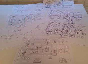
After verifying that my new combined design worked, I then cleaned off all my specific extraneous system info to then submit a generic copy onto the Cozy forum.  I received word back from Marc Zeitlin that it would work as per my (actually his & Jack’s) design, with a number of “why-didn’t-you-use-this-component-vs-that-one” type questions, which is great since that’s how system designs are optimized.  So now I have some system design “homework” from Marc that I will attempt to iron out.

Regardless, doing nothing else from this point on (besides buy all the required components!) results in a new baseline electric nose gear system that provides a very usable AEX system and allows me to incorporate the backup battery feature/emergency gear extend feature.

If you’re curious, here’s a final thought on reasons I chose the battery backup system vs. the mechanical ratchet wrench backup gear deployment system: the battery weighs considerably less, takes up no panel space as does the mechanical unit, and most importantly –for me– if I’m working any non-standard issue while in the process of landing, I don’t want to be messing around with a ratchet (which itself weighs as much as the small backup battery) and spending time getting the gear down when the flick of a switch will do it for me.  Finally, a very important thing to consider that I learned while flying in Marco’s Long-EZ is that IF YOU DROP SOMETHING on the floor, it is no longer something of use to you!  And unless you tie off that ratchet handle, it may end up being nothing more than added weight in your airplane while you WISH you had a means to get your nose gear down [just saying . . . IMO!]

Now, on to my final topic of this LONG post.
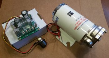
I had a good discussion with both Buly Aliev and Nick Ugolini regarding the integration of Buly’s oil heater system pump and system design.  I have lots to think about still on this system, but one thing I did take away from my discussion with Nick is the heat output is best realized by controlling the speed that the oil pump is pumping in hot oil into the system.  Thus, in able to control the speed of the oil pump, one method utilizes a PWM controller switch, so that’s just what I picked up.  I can now say, “Behold, the oil pump and its PWM controller switch!” (not that I will necessarily, but I can if I want . . . !)

That’s all for now folks!

 

Chapter 22 – Taking a break…

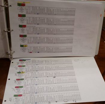
Today I started out studying for my Instrument Pilot’s rating for a number of hours before I hit a serious wall.  My brain was mush so I rationalized spending a few hours on getting my AG6 programming data organized.  I consolidated all the programming parameters onto one sheet per AG6 (they’re labeled AG6A & AG6B), printed them off and stuck them in my Electrical Wire Book right behind Wiring Diagram #18: AG6 Warning Annunciators.

AG6-A & AG6-B programming pages

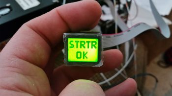
Since I still had the electrical leads connected to AG6 #2 (AG6B), I decided to go ahead and program it as well.  It took me a good hour to get all the parameters dialed in –there are 32 parameters just for the individual warning screen definitions alone– and another 45 minutes trying to troubleshoot an issue with the very last alarm screen: the STRTR ON warning screen (which denotes a hung-up starter) which for some inexplicable reason [at least to me] is only showing the green STRTR OK screen.  Not gonna cut the mustard!

After no joy in troubleshooting the Starter On warning screen, I emailed Rich at Aircraft Extras, Inc. to get his input on how to fix the issue.

I also whipped together a very quick video to offer a little insight into what I’m up to on these AG6 warning annunciators.  Be forewarned!  The AG6 screen colors & labels don’t show up very well.  But you’ll get the general idea nonetheless.

Ok, back to studying!

Chapter 22 – Executive Decision

If you’ve been following my blog you know that I’m on a brief hiatus from building to finish up my Instrument rating.  My plan is to finish up my rating by mid-March, at which point I plan on getting back to the build hot ‘n heavy.  Who knows?!  Maybe I’ll even finish up installing those wheel pants! ha!
One reality that I had to accept as I was preparing for an upcoming Instrument flying stage check was my lack of understanding of the Garmin GNS430 GPS navigator, which is installed in all the Cessna 172s that I fly for training.  I had resisted in really getting deep in learning the GNS430 since for my Long-EZ, my plan was to install an Avidyne IFD 440/5×0 GPS.  But alas, with a couple of stage checks and my FAA check ride looming on the near horizon, I realized that I really needed to nug out some training on the GNS430.  This decision was made easier in part when I received an email from the ubiquitous King’s offering a 20% discount on any of their training courses.   So I pulled the trigger and bought the King GNS430/530 training course (which is pretty good by the way).

As I was just getting into the 430 training, I was thinking I would buy a 430W to install in the Long-EZ since I use it so much in my training airplanes.  With the completion of my Commercial rating still looming on the horizon, I would still require a lot of time behind the 430.  Since the Avidyne IFD440 is a slide-in replacement for the Garmin GNS430W, why not use the 430 now and simply replace it with the IFD440 later?  Sounded like a good plan.  For clarity, I discussed this at length with Marco who agreed with the merits of my logic (although being a big Iron driver, he’s not a big fan of the 430).

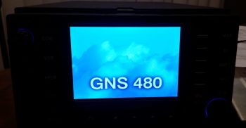
My GPS Navigator choice: GNS480

Although it wasn’t my intention initially, as I dug deeper and deeper into learning the GNS430, curiosity of how its features compared to other units got the best of me.  So during breaks in training I would sneak in quick peeks at the Avidyne and GNS480 features.  As I would Google certain features that I wanted more info on regarding the 430 (holds, OBS, airways, etc.) I kept coming across overwhelmingly positive reviews on those features for the GNS480 [Admittedly from those bubbas flying behind them… to the guys that hadn’t flown the 480s, the report was that the learning curve was ‘too steep,’ the interface ‘too FMS-like,’ and a constant projected fear of no further Garmin support on these units].

As my curiosity deepened, before bed one night I spent a good 45 minutes watching a video specifically on the GNS480 operations.  I was deeply impressed with the power & capability of the GNS480, and every chance I got I would spend a few minutes here and there researching it more.   After a day or so of this, I sent the 480 video to Marco with a good hunch that he’d really like this unit as well (he did!).

If you’ve ever gotten a feel for my modus operandi, it will probably not surprise you that I was already communicating with a number GNS430W sellers in line with my latest 430W plan.  However, there was an oddity playing out during my short-lived quest to acquire a 430W.  First, nearly every seller of every 430W unit that I engaged with turned out to be a scammer.  Moreover, I spent a good week working a promising deal that in the end turned out to be yet another scam.

However, I guess all things work out for a reason, because during the week I was working the potential 430W purchase with what turned out to be yet another scammer (NOTE: nearly every 430W listed on Barnstormers and other sites turned out to be a scam), I was concurrently learning more and more of the GNS480’s capabilities.  Remember, during the majority of this time I was practicing instrument approaches and studying IFR flying. Truth be told, this training was probably the tipping point in my choosing the GNS480 over the GNS430W.  Why?  Well, as I re-flew my recent actual IFR flights and approaches on the respective 480 and 430 simulators side-by-side, the GNS480 clearly had superior capabilities when it came to flying IFR flights and approaches (in my opinion).  [I’ll expound on the specific comparisons in a later post].

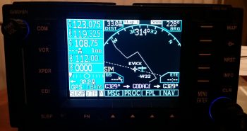
GNS480 Main Map Page

To be clear, with the great price (but not unrealistically low) that I would have paid for the GNS430W that I was dealing on, I would still have gladly bought it and installed it.  My requirements goal here was to install a lower cost WAAS GPS unit that allowed me to fly my Long-EZ IFR.  Nonetheless, by the time I determined that the 430W seller that I was dealing with was a scammer, I reset my search primarily on finding a quality, well-priced GNS480 unit.  Well, in short order I was able to serendipitously do just that, finding a local GNS480 seller (and experienced pilot) that had a unit for sale.

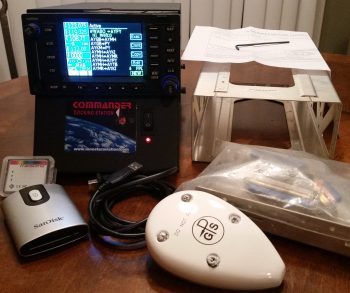
My "new" GNS480 Kit

I met with the seller, Phil, at a local airport where I was able to play around with the unit in its Commander docking station.  The fact that Phil was selling an entire Plug-n-play package was the deciding factor in why I pulled the trigger on this unit.  Here are all the components that were included:

  • Garmin checked & software updated to Vers. 2.4 and 5.1 (allows ADS-B+ out)
  • Mounting tray (“tube”), backplate and electrical & coax connectors
  • GA 35 WAAS GPS antenna
  • Data card reader + 2 data cards
  • Lone Star Commander docking station

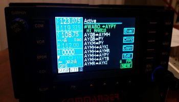
GNS480 FPL screen...w/ comments!

A result of my evaluation, and subsequent purchase, of the GNS480 has brought me to the conclusion that this will be the final and only GPS unit that I plan on installing in my Long-EZ. Clearly this means that my proposed Avidyne upgrade is simply off the table now.  With the GNS480’s handling of voice and nav comms, its inherent WAAS GPS/VOR/LOC/ILS capabilities, and its fantastic handling of airways, I am more than thrilled to have made my decision final in identifying this GNS480 as Long-EZ N916WP’s long term GPS navigator unit.


Chapter 22 – More stuff!

As most of you all know I’m pretty much back in the saddle as far as flying is concerned in my attempt to finish up my Instrument Pilot’s rating.  Unfortunately, I’m definitely not in the saddle where the build is concerned.  In fact, the horse is in the barn and won’t really be ridden for another month or two as far the build.

I have been occasionally taking a break from studying here and there to get a bit of planning and scheming in on some of the miscellaneous electrical stuff that I have yet to finalize.

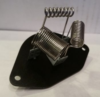
So, I thought I would provide a quick update on some of the pieces-parts that I’ve found to help further my cause.  First off, I finally found a good, cheap basic heater fan resistor coil for my oil heat system.  I got this off of Amazon for about $5.  Not bad, and so far it looks like it will definitely work.

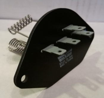
Oil Heater fan resistor coil

Here’s the backside of the oil heater fan resistor coil.  However, since it didn’t come with any specs I had test each of the coil circuits for their resistance values and create a truth table to verify what was what.  It took about 10 minutes, but I verified the entire circuitry of the heater fan resistor coil.

Oil Heater fan resistor coil

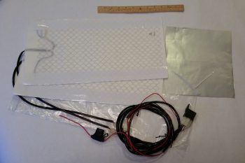
I also ordered a heated seat pad kit for the front seat and/or possibly both front & aft seats (if I can make it work).  The wiring is fairly straightforward and the whole thing will come in under 0.8 lbs. installed.  I think I mentioned it before, but I will be wiring both the heated seat warmers and the oil heat system through a DPDT relay so that only one system can be powered on at any given time.  This is of course to ensure that the charging system, main power bus, and/or battery isn’t overtaxed beyond the capability of my 40A alternator.

Seat(s) warmer kit

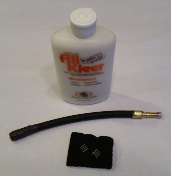
Finally, when I spoke with Rich at Aircraft Extras about adding new AG6 warning screens (shown below) to a couple of new chips for me, I added a bottle of canopy cleaner and a tire air nozzle extension to the order to optimize shipping costs.

Aircraft Extras order

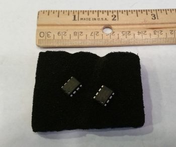
Here are the 2 new AG6 chips that Rich programmed for me.  To be clear, he just didn’t simply program them willy-nilly, but went off a fairly detailed spreadsheet that I created for him that listed out the majority of the field parameters.

AG6 annunciators' updated chips

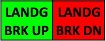
The 2 new AG6 chips include a verified screen description number to display Canopy “Locked” (versus simply “Closed”) . . .

AG6 Canopy Open Alarm

And an updated EZ binary version of Landing Brake Up and Down (versus the already programmed Landing Brake “On” and “Off”) . . .

AG6 Landing Brake Down Alarm

Along with 2 completely new alarm conditions and screen displays:  RAM Air Open and Closed (to ensure I close the RAM air scoop to keep FOD out of the engine) and IBBS Low Volts (IBBS-specific low voltage alarm to show the back-up battery is not charging or is under charged).  I had Rich program these alarm screens as yellow since they fall more in the caution category in my opinion, but I can easily change the colors later on if I want.

AG6 RAM Air Scoop Open Alarm

AG6 IBBS Low Volt Alarm

That’s pretty much all I have to report for now.  I have of course been making notes of any potential system updates or mods as I run across them, but for the most part I’ve either been flying or studying over the past week or so.

Chapter 22 – “Danger Will Robinson!”

As I mentioned before, sideline to getting back into the books and refreshing my tired mind on Instrument flying stuff, I’ve been cleaning up some electrical system stuff that is a natural result of integrating systems and devices together.

One such area of my electrical system is on the warning annunciators.  I decided to crack the code on just how these AG6 annunciators (again, I have 2) are programmed.  Well, the programming manual might as well have been written in Mandarin Chinese when I started, but after working through it bit by bit I finally got the swing of it.  The weirdest thing about these annunciators is that you only have one interface to program them, the button –also the annunciator screen– which makes things interesting.  There are only 2 inputs that the screen recognizes, akin to Morse code: a short press [<0.7 sec] and a long press [>0.7 sec].  It also recognizes the rate and combinations of these presses together (analogous to the ‘double-click’ on a computer).  Again, once I worked at it a few times the input was really a non-issue. Add a little patience and it’s actually something new and fun.

One issue I had was that I failed to realize that there was an online spreadsheet that had the codes that I needed to program (or reprogram) these annunciators.  My being remiss in having this critical document on hand was evident after a few telephone and email discussions that I had with Rich from aircraftextras.com.

AG6 Warning Annunciator Screen

With the spreadsheet in hand I was able to effectively program about 80-90% of the input screens that I wanted.  To be clear, I had the installation manual that described the entire programming process, but what I didn’t have was the spreadsheet that had the required codes to tell me what screen ID numbers to input for the warning screens that I wanted annunciated… until after talking with Rich of course!

AG6 Warning Annunciator Screen

Since the AG6, as with what seems like the majority of experimental aircraft products these days, is traditionally geared towards the RV crowd, there are some unique warning annunciator screens I would like that are not on the list of hundreds of screens already preprogrammed on the AG6.

After finalizing all the programming I could do, I determined that I needed 2 completely new screens and slight modifications to 2 other screens to provide me what I’m looking for in my warning annunciation scheme.  The 2 new screens are “IBBS Low V.” for my IBBS unit, and “RAM OPEN” / “RAM CLOSD” for my engine RAM air intake.

AG6 Warning Annunciator Screen

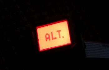
As for the pics above, I would like to point out that the top pic portrays the actual visual appearance the best of these 3 pics.  A brilliant, bright red light is really hard to capture with any of my cameras, and comes out looking orange and pale, and is not representative of its actual appearance (the same thing holds true for the indicators below).

Finally, the top pic showing “CANPY CLOSD” is one that I want changed to “CANPY LOCKD” (there is a screen ID for the latter, but for some reason it too is showing as simply “CANPY CLOSD”).  There will be no “ALT.” screen, but rather “Low Volts” for the main bus low volt state (via the B&C LRC-14 voltage regulator).

The last pic above is the annunciation that will show up for a few seconds immediately following engine start to show that the starter solenoid is not hung up (“hung start”).  As a reminder, a hung starter state is dangerous since huge current flow is rushing through the system from battery to starter and back unabated, which will fry the battery… with even possibly more bad smoking, fiery stuff to follow (Dick Rutan addresses this in CP #99).  To be clear, the more important screens are the red, flashing warning annunciations that will come and stay on until recognized with a screen press, or the warning state ceases on its own.  Thus, the entire time the starter is powered there will be a flashing red light depicting “STRTR ON” until it’s disengaged, at which point the green annunciator screen shown above will flash on.

Moving on…

As I mentioned the other day, in my quest to finalize both my warning annunciation scheme and my device ON/OFF indicators (below) I ran across a discussion from Paul Dye (Editor in Chief of KITPLANES mag) arguing that a simple, separate, non-EFIS or engine management system linked low oil pressure light should be incorporated into one’s lineup as a primary tell-all of engine health if your spiffy, modern glass cockpit goes Red-X on you.

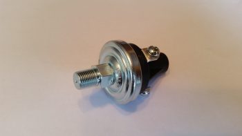
I thought that for 2.3 oz it sounded like some good informational “need-to-know” insurance, so I bought this oil pressure switch from B&C to incorporate its alarm out state as an input into the AG6.  When the oil pressure is low (as in pre-engine start) a red, flashing “LOW OIL P.” annunciation will alarm (this is an adjunct warning light, not a replacement, of the EFIS-depicted engine instrumentation).

Oil Pressure warning switch

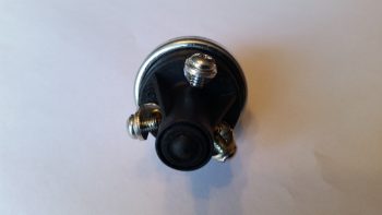
This oil pressure switch actually has 3 electrical connections to allow for a Hobbs meter to be wired up as well, if so inclined.  Here’s the back of the oil pressure switch, showing the N.O., N.C. and COM electrical connection posts.

Oil Pressure warning switch

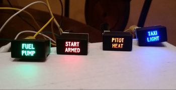
Lastly — something I’m extremely pleased with is these babies below that were delivered today!  Again, as I mentioned before, after I assessed my warning light system I decided that I would revise my original decision to run all but one pair of LED panel indicators through the AG6 annunciators, in order to make the AG6s strictly inflight/actual warning annunciators. Thus, those devices that I simply wanted to know were in an ON or OFF state would get downgraded to just LED lights again.

Now, I did order a myriad of LEDs in one my of Mouser orders, but my spidey sense told me there had to be something better out there.  After messing about online a bit here & there over the past few weeks, I found these.  They’re simple LED indicators for airline cockpit simulators that I found on Ebay (these are 737 panel indicators).  I wasn’t sure if they would work, but at less than $4 a piece, I figured I would pull the trigger and test them out.  I’m very glad I took a chance!

Non-warning ON/OFF LED Indicators

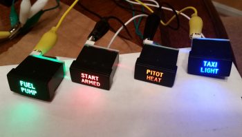
Again, the red and green indicators don’t photograph well, although the blue and amber lights are fairly good depictions of how they look.  These 4 items are the ones which I wanted their ON/OFF states communicated since –other than the fuel pump under my thigh support– I would have no real way of knowing if they are actually in an on or off state (yes, I could tell if the taxi light is on at night, but how about during the day?).

Non-warning ON/OFF LED Indicators

Best of all, these are low current and very lightweight indicators, with all 4 weighing in at less than 0.05 lbs.  I will run them through a dimmer so that their brightness can be dimmed at night, and turned up to their brightest during daylight flying.  One point of note is that I reserved the brightest LEDs (red & blue) for the ground op devices: START ARMED to indicate when the engine starting system is ready, and the TAXI LIGHT on indicator.  This leaves the FUEL PUMP and PITOT HEAT as the less bright, but still clearly visible, indicator lights for flight ops.  In addition, I reserved the only red light, denoting an actual real hazard, for the START ARMED indicator… since a swinging prop typically ensues immediately after it lights up.  So, although definitely listed in the “great-to-know” category, the other indicator lights (and their associated colors) do not denote hazardous states.

Ok folks.  Transmission ended, and back to studying for me!

Chapter 22 – Taxi Light Actuator Test

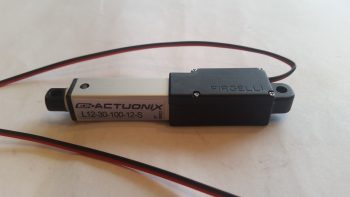
Today I performed a final test for the circuit that drives the Firgelli/Actuonix L12-S mini-Actuator for the swing-down Taxi Light assembly in the nose of the aircraft.

Firgelli/Actuonix L12-S mini-Actuator for Taxi Light

I actually set this up last night and messed around with it a bit.  Unfortunately, I had one power connection off so it wasn’t working in both directions with a simple ON-OFF switch. For a bit I thought I might need a more esoteric relay along the lines of a latching relay until I found my wiring miscue.

This morning I made the correction and Voila! . . . the actuator worked like a champ with the up/down throw of a simple ON-OFF switch!  The ON-OFF switch of course mimics the blue ON-OFF push button located at the bottom front of my Infinity stick grip.

I shot a short video to show how nicely this mini-actuator works, and show a bit of the wiring behind it, including the core part of this circuit: the DPDT relay:

From here on out for the next couple of months I’ll really be focusing on getting my Instrument Rating, so I’ll most likely not be posting nearly as much.  I will be prepping and working on the wheel pants when I get a chance, but as I’ve said before, the build will be my #2 priority for the first couple of months of this year.


Chapter 22 – A bit more electrical

Happy New Year!

Over the holidays I’ve been quietly working on the odd & end aspects of various areas of electrical stuff in my push to get as far as I can on finalizing the electrical system before moving on with the rest of the build.

Yesterday I finalized a 2-day process to figure out the wiring going out to the wing Nav, Strobe & Landing lights.  I had a quick but informative discussion with Dean from AeroLEDs and pulled the trigger on a couple different types of shielded 20 AWG electrical wire and some more connectors from Stein.  I also assessed & designed a reroute of my com radio antenna cables to get them away from the noisy wing tip light wire runs.

With final decisions made on the wing wiring, I finalized updating my wiring diagram for the Landing/Taxi/Nav/Strobe lights.  I also updated the wiring diagram for the AG6 warning annunciators, driven in part by my decision to only have actual warning annunciations communicated by the AG6 displays.  Thus, I decided to transfer the simple ON/OFF LED displays for those items that I merely want to know if they are in an on or off state (start armed, taxi light, pitot tube & fuel pump) off of the AG6s.  I ordered what look to be some high end LED annunciator buttons off of Ebay for these 4 ON/OFF indicators.  I’ll assess those when they arrive and move on from there.

I have one more item to report as for warning annunciators: as I was doing my research for what I should employ as simple device ON/OFF indicators, I ran across a post on the VAF forum from Paul Dye (Editor in Chief for KITPLANES magazine) arguing the merits for having a backup Oil Pressure warning indicator that was not integrated into the glass cockpit system… in other words, not reported by the EFIS or the Engine Management System.  I assessed this for a few days, and finally concluded that if I did have a catastrophic display outage and was looking at nothing but red “X”s on the EFIS displays that it would be nice to have ONE annunciator light to provide the overarching status of my engine health, and oil pressure is arguably (as Paul Dye so eloquently does) the biggest. For a weight penalty of 3 ounces, I decided I would incorporate this backup oil pressure status into my warning annunciation scheme.

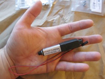
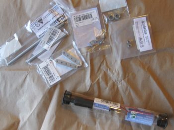
Today I finally received my L12-S mini-actuator for driving the Taxi Light assembly deployment and retraction.  As you can see in the pic below I bought a number of ancillary parts that should facilitate the install.

Actuonix mini-Actuator & parts

Although I knew it when I ordered it, the tiny size of this actuator is really hard to believe until you actually hold it in your hand, which is exactly what I did!  Again, seeing this pic it’s not hard to believe that this thing only weighs 34 grams.

Actuonix L12-S mini-Actuator

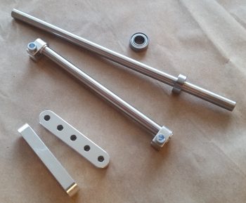
Here’s a shot of the Taxi Light swing down assembly parts that I picked up with the L12-S mini-actuator.

Taxi light actuator hardware bits

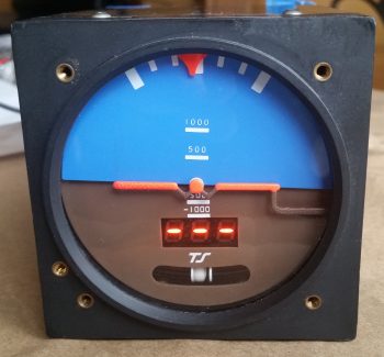
I also decided that I was long overdue in doing a thorough ops check of the Trutrak 3-1/8″ ADI that I picked up off of Ebay from an RV driver as an attitude reference backup to my glass panel.  I did a quick review of the instructions and fired it up.  Since I had the GPS puck plugged in I wasn’t quite sure why I wasn’t getting the GPS track info in the window where the 3 lighted dashes appear.  Well, I got back into the manual, did a quick online search and still couldn’t find an answer.  Hmmm, did I have a bad unit that needs repaired?

I couldn’t ponder on it long since I had to run out and help a friend move some furniture (the bane of being a pick-up truck owner!).  Well, I arrived at the location a bit earlier than they did, so I decided to call Trutrak and find out the story on the 3 dashes.  It turns out that the 3 dashes are normal & that no track info is displayed until the aircraft is in motion…. Ok, another good instrument ops check!

Ops checking Trutrak ADI

Tomorrow I’ll test out my taxi light actuator circuit design & operations by wiring it up to the DPDT relay I have on hand.


Chapter 22 – Electrons vs. Paper

Well, as I pointed out, between the holiday stuff, the football, and more importantly, this nasty cold I’m fighting, I have abided by my previous statement that the build would slow down quite a bit.

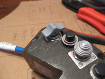
I did finally receive a pack of 1/16″ roll pins that I ordered, so I was able to mount my gray finger grip back onto the landing brake switch post (permanently).  Last year I had to drill out the original roll pin in order to get the finger grip off to then allow me to remove the switch from the throttle handle housing.  In fact, the hole that is now visible on the side (top) of the switch grip wasn’t there when I started last year and was created as a result of my drilling endeavors.  Presently, I put some E6000 on the bottom side of the switch to help seal up the roll pin hole.

Barring any other adventures, this does it for the completion of my throttle handle switch installation, wiring & prep.  Over the next few days, when I start feeling a LOT better, I’ll drill a hole or two in the lower left area of the instrument panel bulkhead to mount some Adel clamps for use to secure the throttle handle cable (and whatever other wiring needs secured).

Air Brake Toggle Switch Finger Grip

The remainder of my work over the past couple of days has been around finalizing the electrical system push. For one, I started compiling a list of even more electrical system components I’ll need for the future (shielded wiring, consumables, etc.).  I also printed out a couple of batches (~12) of heat shrink wire labels and attached some of those.

One main thing I’ve been doing, since I’m really not feeling up-to-snuff, is updating my electrical diagrams.  You can imagine there is simply a myriad of data that needs to be annotated (in digital form, vs. my own chicken scratches!) on these diagrams: wire colors, wire sizes, wire labels –these change a lot with the addition of connectors– circuit changes, etc.  I would say that it’s not uncommon for me to have anywhere from a dozen to 50 data points on each diagram that requires updating, which in and of itself isn’t necessarily or overly difficult.  However, the crosschecking (or consolidating) of ground points, bus tab positions (again, or piggybacking) –and making the decisions on those as well– is what eats up a good bit of time.  And of course there’s the oft required research that may accompany any such decision.

In addition, I’ve done (or simply documented) major circuit design revisions, mainly the items that are controlled via the airspeed switches and/or ancillary relays.  I also did a major overhaul of my panel dimmer and cockpit lighting & dimming circuit design as well. As a point of reference, I haven’t touched this particular wiring diagram since June 2014, so it definitely needed some attention.

I’m about 2/3rds through the diagrams and don’t have that many more to go.  Once I start feeling better, with my electrical system documentation updated, I’ll be ready to start back on some real work . . . like perhaps some wheel pants.  I will note that the wheel pants are most likely the only thing that will get done in the next couple of months since I really need to start flying again: A LOT!