Chapter 22 – Mounting Gear RCU box

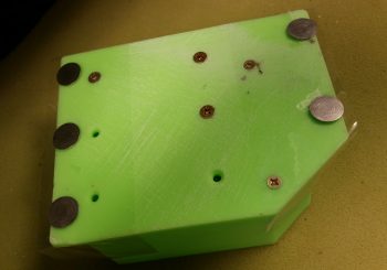
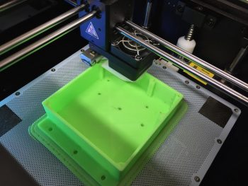
Today I received the Nose Gear RCU box in the mail from Marco.  He did a great job and the relays fit perfectly!  A little too perfectly actually . . . The holes are aligned exactly as I designed them in CAD, except I put them in a little too close to the end wall of each relay so that I won’t be able to fit a normal aviation/MIL-SPEC nut on the screw.

After thinking about this issue a bit I realized that the answer was fairly simple: nutplates. Nutplates are narrow enough that they’ll fit and even though a bit higher cost solution than normal AN nuts, they’ll definitely do the trick.

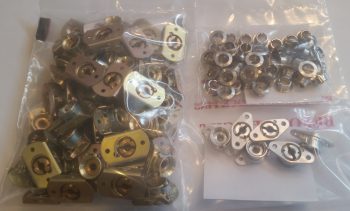
With the relay mounting issue out of the way, I prepped the box to be mounted with 5 Clickbonds.  The mounting holes’ diameter were just slightly narrower than designed, so  I spent a few minutes drilling those out to size.  I then taped the back side of the box with clear packing tape.  After roughing up the back sides of the Clickbonds with sandpaper, I cleaned them with Acetone.  I then mounted them in the box, whipped up some 5-min glue and put a good dab on each Clickbond face.

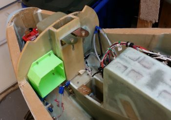
I then mounted the box on the aft side of the Napster bulkhead aligned with some position marks that I had previously made.  I held the box in position for a little over 5 minutes to let the 5-minute glue cure.

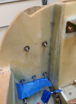
With the 5 Clickbonds attached to the aft face of Napster I pulled the RCU box off of the bulkhead.  The Clickbonds set well and the attachments were solid.  I cleaned up some of the 5-min glue gunk and left the Clickbonds alone to fully cure.

While the Clickbonds cured, I measured out the dimensions I would need for the BID tapes for the top and bottom row of Clickbonds.  I wanted at least a good inch from each Clickbond stud to hold it securely in place.  I cut 3 plies of BID 2″ high and with a slight angle for the outboard side of the upper row, for a total of two sets of 3-ply BID.  I then configured the BID plies in plastic for pre-preg setups and called it a night.

Chapter 22 – March Madness Brackets!

Well, My March Madness brackets!

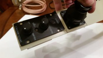
Today I started working on the brackets for both the P4 throttle connector bracket and the Intercom bracket.  As for the Intercom bracket, I decided that I’ll most likely make the right pilot armrest removable to gain access to intercom wiring.  So the intercom mounted in the bracket will remain on the sidewall, allowing the armrest to be pulled away from it.

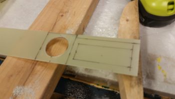
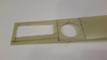
I started off by determining the dimensions of each bracket, and then marked up a 1/16″ piece of G10 with these dimensions.  I then drilled the 1.5″ hole for the Throttle P4 AMP CPC connector.

I then cut the rectangular hole for Dynon Intercom.

And then test fitted both the Intercom and the P4 connector, with both fitting just fine.

After prepping the holes I took the evening off to go to dinner.

Chapter 22 – Cables, cables, cables

Today’s post is just a quick update showing some cable builds.

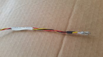
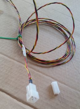
First off is the 3-wire braided cable for the Nose Gear Auto Extend laser altimeter.  These three 22AWG wires will provide power, ground and signal path from the laser altimeter into the Auto Extend Module (AEM).

After terminating the wire ends with mini-Molex pins (above) I then inserted the pins into a connector body.

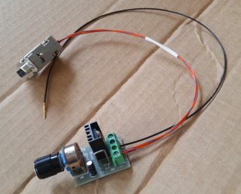
I also soldered 2x 22AWG wires to a 9-pin DSub connector to make up the connector that all the panel components that require an external dimming control will tie into.  The black wire with the DSub pin is a ground wire to the avionics ground bus (G5) for the dimmer module shown at the bottom of the pic below.

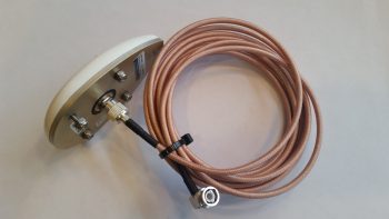
Finally, although I didn’t make this cable, I thought I’d show it just to hint at a bit of progress on the GPS navigator install front.  I ordered a 12′ RG400 cable with a TNC connector on one end (mounted to the GPS antenna in below pic) and a 90° BNC connector on the other end.  Since I only need around 6′ for the GPS antenna, I’ll use about half of the RG400 cable and the BNC connector somewhere else.

That’s all for now folks!


Chapter 22 – Wiring AEM components

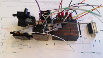
Today I finished wiring all the components of the Nose Gear Auto Extension Module (AEM) as far as I could without having the physical box in hand.  As I’ve mentioned before, the AEM is simply an upgraded replacement of Jack Wilhelmson’s Nose Gear AEX system that utilizes Marc Zeitlin’s design to incorporate a few more parameters into the Auto Extension system to pretty much eliminate annoying false-positive situations and ensure that really the only time the AEX will deploy the gear is on final approach when you actually forgot to put the gear down.  To make the magic work, Marc added another airspeed switch (for a total of two), a throttle mounted “microswitch,” and a laser altimeter.

I decided to cram all this new stuff into a box approximately the same size as the original AEX box.  Since Marco is 3D printing this one as well, it will have holes ready to go for mounting the internal components and some external mounting flanges for attaching the box to the forward side of F22 with Clickbonds.

The laser altimeter operates on 5 Volts, so it requires a 12V-5V converter.  However unlike Marc Z. I chose to mount the converter up front versus the way he did right next to the laser altimeter (which is on the belly near the main gear).  There is no right or wrong here regarding the location of the voltage converter, I just simply wanted to drive the weight forward and also hide the converter away in the AEX box.

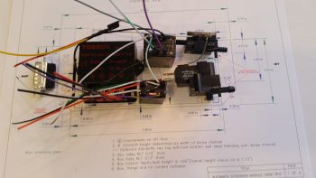
In between the voltage converter (right, below) and the airspeed switches (left, below) are two relays.  These relays are unique to my specific system since these are the ones I needed to wire into the mix if I wanted to continue to use my throttle-mounted toggle switch to control the nose gear up/off/dn.  These relays are fairly small and light, although robust, so the weight penalty is negligible.

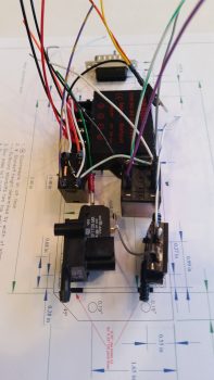
Finally, in each pic I show the 15-pin DSub connector.  In the very top pic, and the one below, you can make out the black bar that depicts the hole for this DSub connector on the actual-sized box CAD diagram lying below the components

As with my RCU components, the only thing left to do with these are to physically mount them into the box and then cut & terminate the wires with DSub pins.  I do have a few minor tasks that I can complete for the final prep of this system before I have boxes in hand and am ready to install.


Chapter 22 – Gear RCU Wiring

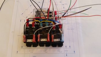
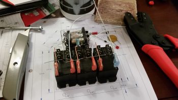
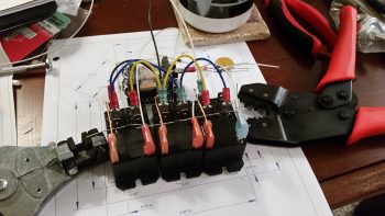
Today I finished wiring all that I could on the Nose Gear Relay Control Unit (RCU).  My first task of course was to trim the lengths of the cross connect wires to the outboard relays (#1 & #3).  I then re-terminated the wires with new red FASTON terminals and double checked that all was good with those.

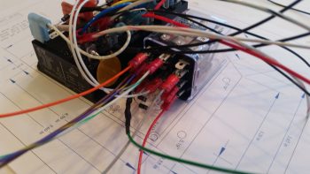
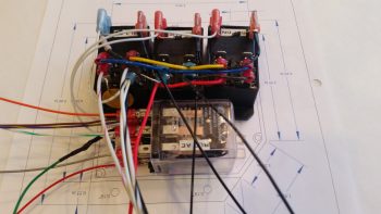
I then started cross-connecting wires from the 3 lower relays (black) to the top AEX relay (clear).  One of the big challenges, which I think is a bit analogous to solving a puzzle, is to take the logical wiring diagram on paper and determine how the wires and components actually hook together in real life.

What looks like a long wire on the page can of course be no wire and simply a lead to a diode or resistor.  Such is the case with the RXEF250 Minifuse that looks like a brown wafer overhanging along the top side of relay #3.  Although on the diagram this shows up in the middle of wire run, in fact this Minifuse IS the wire run.  The diodes at the bottom of the relay connections in the pic below is also pretty much the same way.  On the diagram it looks like 3 diodes suspended mid-point in wire runs, when again they are the wire runs, all starting out at the AEX relay coil’s negative post.  Out of 3 diodes hooked to the coil post, only one them is physical attached to a wire, while the flyback diode is terminated with the positive power wire, and one is simply a loner heading off by itself to a Common terminal.

The wires going every which a way again will get corralled, secured and terminated into the 19-pin AMP CPC connector.

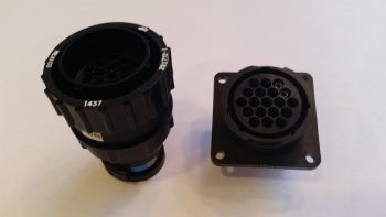
Speaking of connector, here is the AMP CPC connector for the gear RCU.

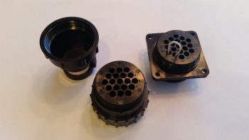
And a shot of the aft side of each connector half.

Besides physically mounting the relays, double checking the wire terminations & cross connects are correct and the terminals are attached tightly, the only thing left to do is to cut the wires to length and terminate the ends to fit into the connector.  Thus, on to wiring the AEM!


Chapter 22 – Initial gear RCU wiring

With the Nose Gear AEM box designed in CAD and sent to Marco for final collaboration and then 3D printing, I got organized to start wiring the internal components of both the RCU and the AEM.  Since the weather is getting better only sporadically, with the seemingly incessant high winds as the norm, I figured I would trudge on to finish up as much of my electronics as possible until good weather allows me to fly & glass.

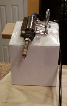
The first order of business was implementing the $1.49 clamp I picked up at Michael’s to allow me to employ the fixed iron method that is detailed in a Youtube video that Marco sent me, and also as I had seen prior in an EAA soldering video (featuring one my local Chapter 186 members, Dick Koehler).  After using this method a bit without the clamp, I really liked it so I bought the clamp and made up my poor man’s version of it:

And here’s the YouTube video on the fixed iron method:

Ok, let’s talk about box configuration.  For mainly external reasons, I needed my RCU box to be no more than 2.1″ tall internally.  This meant the space for wiring connectors would be tight, and might have meant a fair amount of soldering, which as you can see above, I was fully prepared to do! ha!

Well, late last summer I had disassembled a friend’s dishwasher to get rid of it and recycle the parts.  I threw the wiring harness in the garage to use for test wire (vs Tefzel) any time I needed “trash” wire.  Well, I had it upstairs since I was cutting off pieces of this wiring harness to test circuits, and low and behold I found some 90° right angled 0.25″ FASTON connectors on the harness.  I cut them off and inspected them closely and was able to pull away the wires’ outer insulation from the plastic retainer to reveal bright shiny copper underneath.  Since the clamp part of the connector was spotless, I decided these would work great for the 22AWG ground side of the relay coils and pressed them into use.  Since I didn’t have enough, I bought a few more for the relay coils’ positive terminal sides.

Here I’ve laid out the components further so the wiring flows in accordance with the wiring diagram.  I crimped the normal FASTON terminals in place on the relay interconnect wires, first bending the terminals very slowly & carefully at a forward angle to give me just a bit more clearance under the lid.  Also, you can see on the blue flag connector on the right relay that besides the 18AWG power wire, I crimped the flyback diode and 56.2 Ohm resistor into the terminal as well.

[NOTE: my relay interconnect wires came out too long –meaning too tall to fit under the RCU box lid– so I need to cut the wires shorter & re-terminate the terminals on the outside relays].

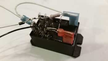
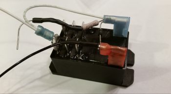
I then focused on relay #3, which is the heart of incorporating the small 1.2A backup battery into this system, as Jack has in his original nose gear system (Note: Marc Z’s version doesn’t have this relay since he uses the mechanical gear down backup system).  I soldered the flyback diode in place between the relay coil tabs, then soldered the 22AWG black ground wire in place, with all this soldering taking place at the red terminal.  I then soldered a Schottky diode (middle left) to the resistor going to the positive side (blue terminal) of the relay coil.  This Schottky diode & resistor make up the backbone of the charging circuit for the 1.2A backup battery.

I then covered my solder joints with heat shrink tubing.

With that, I called it a night knowing that tomorrow I’ll have to cut my relay interconnects shorter and re-terminate…. (big sigh)


Chapter 22 – Gear Relay Control Unit

Over the past couple of days I’ve been designing what I have come to term the Relay Control Unit (RCU) box in CAD  [prior to this multi-day endeavor I spent a day and a half rewriting & reconfiguring John York’s CSA article on installing FeatherLite’s strake & strake leading edge kit specific to my build, and adding in all my past strake construction notes from Mike Beasley, Bernie Siu, Wayne Hicks, Dave Berenholtz … just to name a few].

With the incorporation of Marc Zeitlin’s new wiring for the nose gear Auto Extension System (AEX), which is essentially a redesign of Jack Wilhelmson’s entire electrical scheme for the nose gear, I wanted to get this new system as organized and compartmentalized as possible.  In short, I wanted the rats’ nest of wires gone and out of my nose compartment.

Now, the 3 main components making up my new electric nose gear system is still Jack’s electric nose gear actuator at it’s core, with the actuator motor and limit switches all tucked away under the NG30 cover.  The wiring exits the NG30 cover via a 14-pin AMP CPC connector and heads in two directions: 1) the new Relay Control Unit (RCU) that will reside on the left, aft side of the Napster bulkhead, and 2) the new Auto Extension Module (AEM) which is simply a replacement unit for Jack’s AEX box.  The AEM will sit in the same spot on the front CL of F22 in the top, aft notch in the NG30 cover.  The RCU will tie into the system via a 19-pin AMP CPC connector while the AEM will be connected via a 15-pin DSub connector.  Beside the larger backup battery and laser altimeter, there are minor few connections to the Triparagon, P4 Throttle Connector, and panel switches.  But for the most part, the lion’s share of the actual nose gear electrical system is contained within 3 major components: NG30, RCU & AEM.

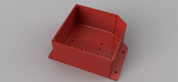
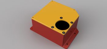
I was drawing up a version of the box I wanted in my antiquated TurboCad system, when in a discussion with Marco he graciously offered to 3D print the boxes for me (maybe not quite understanding that my CAD kung fu wasn’t up to par with his!).  He had to redraw my neanderthal CAD drawings into Fusion360 but in the end came up with the awesome box rendering you see below (note: the angled corner is the top left box corner and is specifically shaped to allow it to fit with the curvature of the Long-EZ’s nose at its install point).

After some further discussion we came up with the lid design that will also be the attach point for the AMP CPC connector, since –YES– space is tight!

After confirming the myriad of little details on this box, Marco pulled the trigger and made our RCU box collaboration a reality.  Pretty cool, eh?!

With the RCU box design complete and construction underway, I then got to work on designing the AEM box.


Chapter 23 – The Skybolt of tomorrow…!

After another quick consult with Nick Ugolini, and after finally getting to the end of the proverbial research road on my Camloc/Skybolt solution (based on Nick’s fastener test) I had a Skybolt order sitting on my computer screen ready to go.  I wasn’t planning on buying these parts this month but since I had just spent over an hour performing some online price comparisons, and these were the lowest price I could find, I decided to not keep this in the queue any longer and pulled the trigger.

So, as with most everything on this build, besides the inevitable nickel & dime onesy-twosey pieces that will crop up and need bought, this purchase does it for my Camloc/Skybolt 1/4-turn fastener system.  This will allow me to virtually (but not completely) go Camloc on my cowlings, RAM air/hell hole cover, internal cockpit hatch covers, etc.

Concurrent to my Skybolt research and order trigger pulling, as I was watching Mike Beasley’s progress on his baggage pod installation, with the help of the ubiquitous baggage pod install master, Steve Beert, my curiosity around some particulars of the baggage pod installation got the best of me.  So late last night I pulled out my notes and ended up back on James Redmon’s Berkut13 site to see what he had to say about it.

I knew that if I wanted to use Camlocs on my baggage pods that I needed to use the removable grommet 4002-NS vs the SK-O18S grommet that is held in place with a snap ring.  If these numbers are new to you, welcome to the club!  As with so many components on these airplanes there are literally hundreds, if not thousands, of possible combinations.  Thus, I’m very thankful that Nick Ugolini documented his Camloc test.

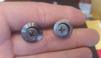
Moreover, you may note that the the face of these grommets below look a bit different (to be clear: the grommet is the flange looking deal while the stud is the “screw”).  The one on the left is the non-removable (without tools) Skybolt SK-O18S, which I’ll be using for the majority of my Camloc installations.  The Camloc 4002-NS grommet on the right is meant to come out when the Camloc is unfastened and is used in places like the aft edges of the cowlings and on the baggage pods.

This view below clearly shows the difference between the SK-O18S on the left (secured to the cowling with a snap ring) and the removable 4002-NS on the left (for aft top/bottom cowling securing and baggage pods).

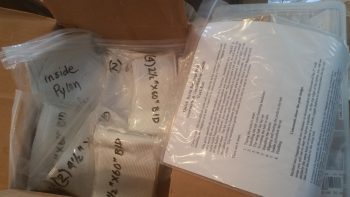
In addition, I discovered a nice surprise while re-reading stuff about installing the baggage pods on James Redmon’s Berkut13 site: he mentioned that Gary Hunter provided all the BID tapes required to mount these pods to your Long-EZ!  What?!  So I went digging in the box that I’ve had for a few years now and sure enough at the bottom was a box with the instructions in there and a bunch of MARKED bags with the BID required to mount the baggage pods . . . Now, how cool is that!!!  Who knew?!  ha!

One final point.  As I was reading through the how-to manuals & notes on installing the baggage pods, I discovered –the day after I got my Skybolt order!– that I needed one more of the -7 studs that I of course don’t have on hand.  See?!  I told you!  Build an airplane if you love never-ending goose chases… ha!


Chapter 22 – COM1/COM2 Radio Swap

After pulling the trigger on my Garmin GNS480 I was doing some research on wiring it up when I found a post on the Dynon forum from a Dynon tech saying that the Dynon 2-place intercom should no longer be used to control two radios.  The huge selling point for me in buying the Dynon intercom was SPECIFICALLY that it was designed to handle TWO radios!

In a phone call with a very knowledgeable RV builder, Don, who I met on the Aeroelectric Connection forum and who happened to also be selling a Garmin GNS480, I pointed out my recent discovery regarding the Dynon statement on their intercom.  Don stated that he knew a number of RV drivers that were using this exact intercom to control two radios and they seemed really happy with their installations.  He further stated that since he was good friends with Rob Hickman, founder of Advanced Flight Systems, that I should give Rob a call to confirm this not-so-good information.  So, I did just that.
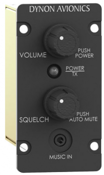
Rob and I talked for a good bit, and he did in fact confirm this disturbing news regarding the Dynon intercom (AFS sells the same exact intercom, and yes, these companies are now one….).  According to Rob, he knew of no work-around and that unless I wanted to keep my COM2 radio turned off or the volume all the way down, I would almost certainly get bleed over and crosstalk between the two radios.  In essence, he said the intercom simply came down to being a hopeful design in theory, but not a good one in practical application [as an aside, none of the advertising that I saw on this intercom changed to state that is was no longer a viable solution for controlling two comm radios].

I looked around for other alternatives but I was really relying on the size and touted functionality of this intercom as the linchpin of my two comm radio design in my Long-EZ. Every audio panel I found simply took up too much panel real estate that I just didn’t have, and the features were either way too much or way too little for what I had already dialed in with the Dynon intercom.  I figured in my mind there needed to be a way to make this little intercom do what it had been advertised to do.

Well, I posted my question on the Aeroelectric Connection forum (if you’re not on it, I highly recommend it) and got a response the next day with a link to the VAN’s forum.  There, an RV builder who moonlights as an electrical engineer (or is that vice versa?!), Deene Ogden, who had the exact answer to my issue.  In the Dynon intercom manual it merely has you hook up the intercom to common on a switch (or relay) with one side going to the COM1 radio and the other going to the COM2 radio.  Well, that results in the crosstalk issue I highlighted above.  The answer is simply go bigger, as in a bigger switch or relay.  Instead of a single pole relay (the white one below) I needed a 3 pole relay to also switch the Audio OUT of each comm radio into the appropriate pin on the Dynon intercom.
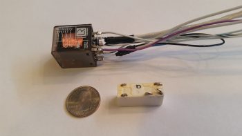
Thus, with the relay off (my control stick switch in the center off/COM1 position) the relay is as follows (1-3 represent the C-NO-NC set for each pole):

  1. PTT: COM1 (NC)
  2. COM1 Audio In: On/NC
  3. COM2 Audio In: Off/NC (pin not connected)

When the relay is powered on (my control stick switch moved up to the ON/COM2 position) the relay is as follows:

  1. PTT: COM2 (NO)
  2. COM1 Audio In: Off/NO (pin not connected)
  3. COM2 Audio In: On/NO

This is reported by Deene and others to do the trick, so as you can see above I bought & rewired/re-soldered the connections to a 3PDT relay.

I also have been doing a bit of verification on my headset jack connections, so below I used the wiring harness that I received with the intercom that I bought from Dick Rutan to test the headset jack housing configuration (yes, I’m name dropping because it’s pretty cool that I’m using something Dick Rutan constructed to check out my configuration!)
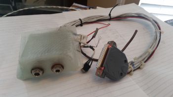
I of course need to finish up my COM1/COM2 swap relay with some heat shrink tubing & wire labels, but beyond that I’m done (again!) with my com radio swap relay wiring.

 

Chapter 21 – Newton Fuel Caps

I got a note from fellow Long-EZ builder Brian Ashton from Alaska asking a question about my fuel caps that I mentioned in a post on acquiring fuel cap keys from ACS for these caps.  Well, to answer Brian’s question I had to go back and do a bit of research on my own fuel caps.  Turns out, I was remiss in ever actually posting anything about my fuel caps, so I am doing that now to correct my oversight!

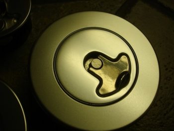
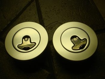
Way back in May 2012 –after a back & forth discussion with a builder that decided he wasn’t going to use these caps anymore– I bought these Newton fuel caps on Ebay.

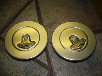
These are the locking style caps as you can see in the pic below.

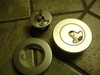
I was looking for the Newton A36LFF style caps with the solid flange vs. the flange that has bolt holes around the perimeter for attachment.  I believe these are slightly different than the A36LFF in that the flanges on these are simply sans holes, while if I’m correct the actual A36LFF has a raised lip around the cap and a slightly lower flange to allow it to be glassed in place.

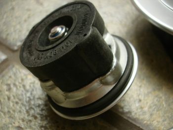
Below is a shot of the interior side of the fuel cap.

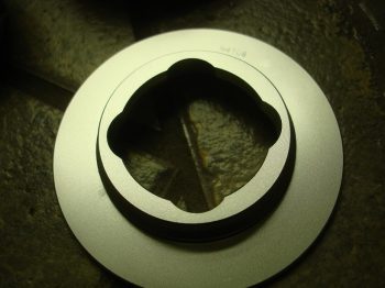
And a shot of the retaining flange, underside.

I definitely remember for the price that I would make this configuration work since the pair of these caps were way less than buying just one A36LFF cap from ACS!  Plus, the flange showing on the external fuel tank surface versus just the cap peeking out is much more visually appealing to me.  I understand the issues of securing it, and I have an idea or two that will keep these guys in place.

One cap does have a couple of very light scratches (which I believe will happen over time anyway) and I’ll make a point that while these have a goldish appearance in all these pics (from the original seller) they in fact have the normal fuel cap silver aluminum finish.

Ok, with the mystery of the missing fuel caps taken care of, I’ll press on!