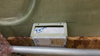
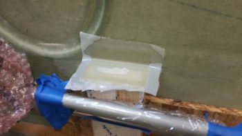
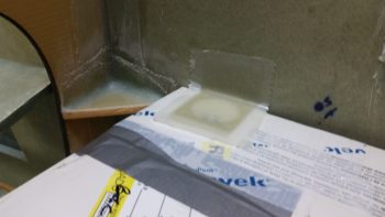
Chapter 22 – Taxi light adventures

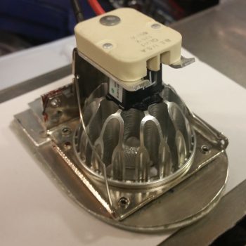
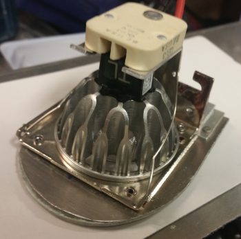
Today I removed the swingdown taxi light assembly from the fuselage to work on it in preparation for the final taxi light system install.  The first order of business was a long overdue trim of all extraneous metal to get this thing lightened up a bit.  I marked the areas to be trimmed in brown Sharpie, as you can see below on the right side . . .

and the left.

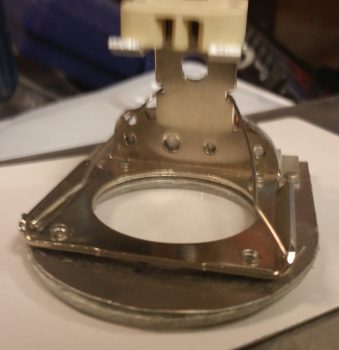
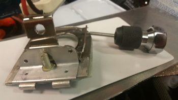
Here’s a not-so-great shot of it after I trimmed off the excess metal areas.  I also drilled the hole in the aft upright arm a little bigger as well.  In all, I trimmed well over 25% of the weight off of this taxi light assembly.

I then drilled and tapped the lower side taxi light bulb frame for two 4-40 screws on each side, to eventually use to keep the taxi light cover mounted.

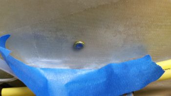
After reinserting the bulb, I then cut out some cardboard pieces and taped them to the taxi light frame for a mold for the taxi light cover.

I then prepped 1 ply of BID, 1 ply of UNI (because I have a ton of spare UNI) and 1 ply of carbon fiber in a prepreg setup to layup on the taxi light cover.  Well, using prepreg here didn’t work so well, since I didn’t allow enough flex with 3 plies for the sharp corners. Worse yet, the CF started splitting at the tight corners and the whole layup quickly devolved towards sheer calamity.

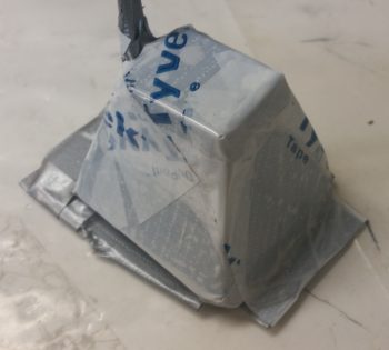
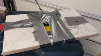
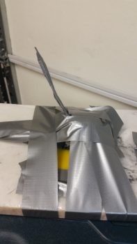
I ended up pulling the entire layup off the taxi light cover, cutting it into about 5 manageable pieces, and then inverting it so the areas of separated carbon fiber were on the inside of the layup.  After placing the disparate pieces of glass in place, I wrapped the whole thing with Saran (plastic) wrap and taped the hell out of all of it.  I figured it would require a fair amount of subsequent work, but I wasn’t just about to through all that glass away.

Here’s another shot of my taped “layup from hell!

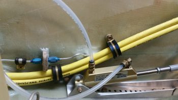
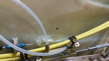
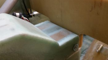
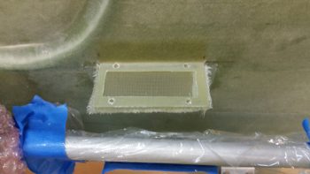
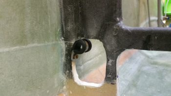
On a brighter note, here’s a shot of how my first added Adel Clamp for the big power cables traversing the length of the fuselage worked out.  I’ll add a subsequent one the next time I whip up some epoxy.

For tonight, I’ll just let the taxi light cover cure and deal with the mystery tomorrow.


Chapter 22 – Finished intercom bracket

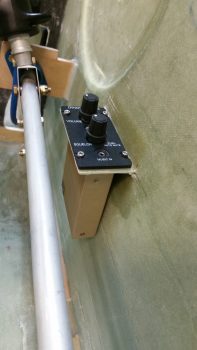
Today I finished getting the Dynon intercom installed into the intercom bracket that I just glassed to the sidewall.

I hate to admit it, but with the curve of the sidewall that I failed to take well enough into account, I had to move the forward two K1000-6 nutplates inboard just a hair to get the intercom to mount correctly.  The front nutplates were off a bit, especially in conjunction with the aft 2 nutplates.

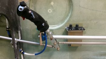
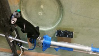
The lower body of the intercom just barely kisses the sidewall on the forward side, which is close to perfect as far as what I was looking for on the angle of the intercom.  I’ll stick a piece of double-side sticky tape foam at that corner and it will keep everything nice and tight, with a little separation between the intercom corner and sidewall.  In addition, in the pic below you can see that the stick is all the way left that it can go before the bottom of the control stick bracket hits the sidewall.  Sitting in the airplane this action would most likely be near impossible to accomplish at this severe angle of bank since the pilot’s leg would be in the way (at least mine would be!).  Regardless, my point is that even with the control stick maxed out to the left, there is still clearance between the lower control tube and the lower intercom box.

Moving on.  Later this evening I figured out my big power cable reroute which is essentially a Bell Curve looking deal that goes up & over my right rudder pedal travel path.  After having to move the rudder pedals forward, and having skooched them in a bit close to the sidewalls, I could no longer run the big power cables along side the right rudder pedal as I had planned for originally.  The fit was very tight before, but after moving the pedals forward it just simply wasn’t going to work.

Rerouting the big power cables worked out for the best anyway though, considering if I had gone with my original plan I might not have known how tight the rudder pedal and big cable clearance situation was until I tried to adjust the rudder pedals forward for a taller pilot (or if I hit another growth spurt… ha!)

Thus, the process of rerouting the big power cables is the same as eating an elephant: I’m doing it one bite at a time!  Tonight I drilled the first new hole in the nose sidewall and prepped it for inserting a Rivnut.

I then prepped the Rivnut by taping up both ends, and then floxed it into the hole.

I’ll let this Rivnut cure in place, then mount the cable with an Adel clamp in the Rivnut before figuring out exactly where the next Adel clamp needs to go.  I’ll then flox in the next Adel clamp hardpoint, let it cure, and repeat the process until I get the big power cables over & around the right rudder pedal and to the instrument panel . . . at a minimum.


Chapter 22 & 25 – Done, Done & Done!

Today I got a few things checked off the list.

First, I finished constructing a micro spreader to hopefully accelerate the finishing of the aircraft surface in prep for painting when the time comes.

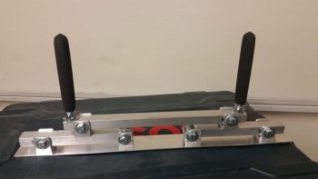
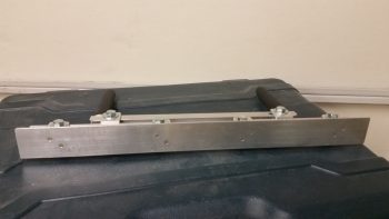
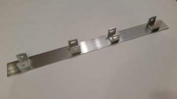
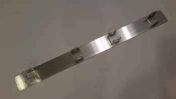
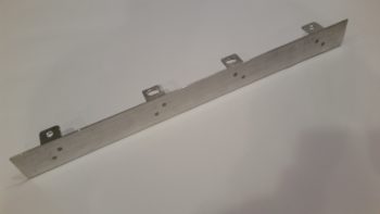
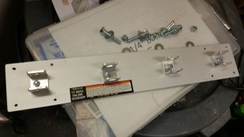
Here’s a shot of the actual bottom plate working surface.  You can see I used 2 counter sunk aluminum rivets per bracket to hold the bottom spreader plate to the 4 individual brackets.  I figured 2 rivets per bracket would be enough since the primary force on the spreader plate is from the top as it pushes the micro over the aircraft skin.  If there is any issue I can of course beef up the bracket attach points.

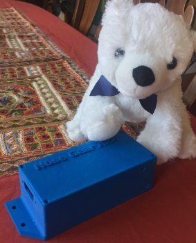
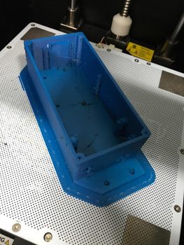
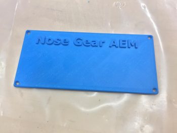
Next, I got this pic from Marco showing my finished Nose Gear AEM box and a United Airlines bear he picked up for my little 7 year old buddy (a friend’s daughter) who loves flying.

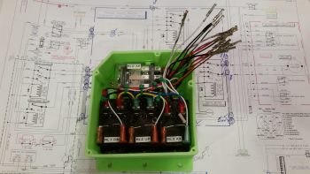
Finally, the box Marco 3D printed for me for the Nose Gear RCU had a slight blemish on the lid, so I’ll hope he’ll forgive me for me filling it in a bit and painting the lid black.  Here’s the finished Nose Gear RCU box ready for mounting into the aircraft.  I will of course have to terminate the wires on the “B” side of the connector.

With my bridge sander, micro spreader and RCU box distraction projects out of the way, I can now get back to my list of electrical system related taskers that need to get knocked out.


Chapter 25 – Finishing Tools

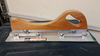
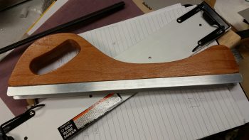
Today I drilled the U-channel on the Harbor Freight handle base to allow me to mount it to the bridge sander.  Before I bolted it all together though, I trimmed the inboard edges of the two cross supports at a sharp angle, and trimmed down the height of the U-channel brackets that hold the handle in place so that there would be no interference by the handle of the sander’s operation.

After all that was done, I bolted it all together and tested it out.  Looks like it will work great!

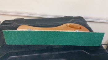
As you may be able to tell in the pics, I mounted some 32 grit peel-n-stick sandpaper to the bottom plate, and it fit just about as perfect as it can get.

Thus, the bridge sander construction is complete and this baby is operational!

I then got to work on constructing the micro spreader.  I cleaned up all the brackets by filing down the edges.  I then measured, drilled and mounted the brackets to the micro spreader base with 2 aluminum rivets at each bracket.

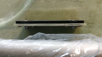
In this shot below you should get a decent shot of the rivets that are holding the brackets to the base.

Here’s the underside of the spreader base, with the 2 rivets per bracket visible.

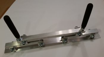
It’s a bit late and I didn’t want to make any more loud noises building this thing, so I called it a night and mocked up the micro spreader to see what it will look like when I finish it tomorrow.

That’s all for now folks . . .


Chapter 22 – 3D Printing AEM Box

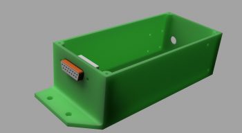
Not me of course!  I just got these updates from Marco.  After some trials and tribulations with his 3D printer he was finally able to get a good print on both the AEM box . . .

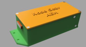
… and the AEM box lid.

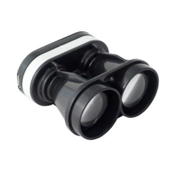
Since I pulled the trigger on the Laserware SF11/C laser altimeter I will soon have all the components required to implement Marc Zeitlin’s new nose gear Auto Extend System, with a twist of course: the backup battery emergency gear extension feature.

To get an idea of what it will look like installed, this is Marc Z’s laser altimeter installed on the inside of his Cozy gear leg cover.  Of course the Long-EZ doesn’t have this gear leg cover, so my laser altimeter will get installed inside the hell hole near the gear.  Also, note in the pic below that Marc mounted the 12V-5V converter near the laser altimeter, whereas my converter will be located in the AEM box above.

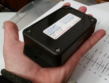
Finally, in a discussion I had with Marco I send him this pic of my GRT Mini-X Magnetometer.  Since I had it on hand I thought I would post it here.

It’s been a bit of effort to get Marc Z’s new gear system implemented, especially with redesigning the 1.2A backup battery emergency extend circuit back into Marc’s scheme. But in the end I think all this extra effort will definitely result in a much more refined, simple, optimized and user-friendly nose gear system.


Chapter 22 – Nose Gear AEM Box

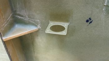
Here’s the latest status on the Nose Gear Auto Extension Module (AEM) that will replace Jack Wilhelmson’s original AEX feature.  First off, I sent this pic to Marco to help show him why I had a requirement that the AEM box be 1.8″ or less: since the AEM box will be mounted in the old AEX box spot, where I have a notch in the top aft side of my NG30 cover that is just a hair wider/deeper than 1.8″.

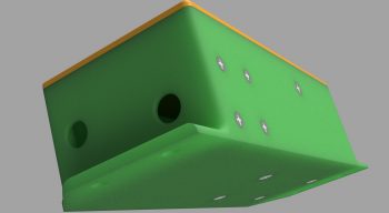
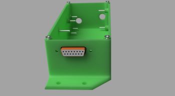
After a number of discussions back & forth with Marco on the particular specs of the AEM box he was able to generate these fantastic renderings of the box.

Here’s the initial rendering.

Then one with the lid and raised letter labeling.

One of the aft, left and top side.

Finally, one showing the internal standoffs for the two airspeed switches and mounting screws.  As you can see, he has included the 15-pin D-Sub connector in the renderings as well.

In the next few days Marco will 3D print this AEM box when he gets a chance.  I just really have to say that everything for the new nose gear wiring & AEX system is going exceedingly well!


Chapter 25 – Self-rolled Bridge Sander

I took a bit of break from my normal build actions to do a quick tool building project. Starting yesterday & finishing today I’ve been working on constructing a bridge sander as Nick Ugolini spells out how to do on his blog.  Once again, I was notified of this brilliant contraption by the watchdog of the canard world, my friend Dave Berenholtz who is blazing through his Long-EZ build down in OZ (check out his blog here).  Coincidentally, Mike Beasley also built one of these as he was finishing up the major sanding of his Long-EZ as well.

For the base, Nick calls for using 1/16″ thick x 1-1/2″ wide aluminum that you can easily buy from Lowe’s, Home Depot, etc.  I did pick up some of that aluminum for the micro spreader, but for the sander it just wasn’t wide enough for me so I picked up a cheap automotive rigid sander at Harbor Freight after assessing that the aluminum base looked as if it would be amenable to getting pressed into service as a flexible sanding board.  As for parts, one other point of note: Nick calls out for 1″ square tubing to be turned into 6 U-channel pieces and then a separate piece of 7/8″ U-channel to be used inside the 1″ share tubing/U-channel above.  Well, I found the 1″ square tubing, but not the 7/8″ U-channel so I ended up using some 1″ wide U-channel I had on hand with 1/8″ walls, then buying 3/4″ U-channel to go inside that.  Just a slight variation that worked out really well.

I started off by ensuring that I could dismantle the Harbor Freight sander to ensure I wouldn’t destroy it in the process.  I peeled the rubber pad off the bottom of the base to gain access to its 4 handle mounting screws.
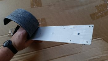
I simply used my fingers to pry off the bottom rubber pad, with an occasionally use of my utility knife to round up any errant pieces of rubber that decided to stay on the aluminum rather than come with the rubber pad.
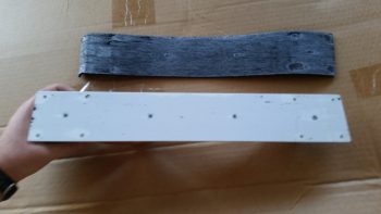
With the sander broken down into an acceptable number of pieces, I then did a final assessment on whether the aluminum base would be flexible enough to be used in this type of sander.

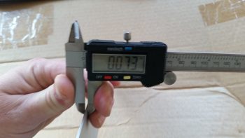
Since the base off the HF sander is only 0.01″ thicker than the 0.063″ (1/16″) called out for by Nick, it looked as if my eevil plan was going to work!
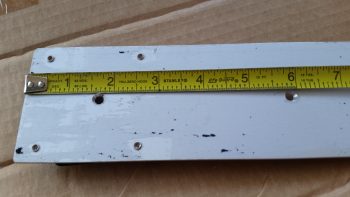
An added bonus in using the HF sander was that the screw holes in the base for holding on the wood handle are at the perfect dimensions that Nick calls for on his blog: approx. 1-1/2″ and 6″, respectively, from each end.  Pretty cool.
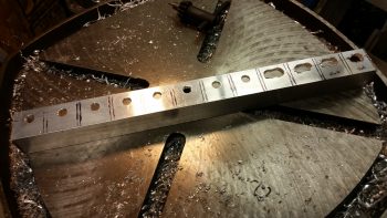
I cut enough of the brackets and aluminum pieces for two of these things since I’ll also be building the micro spreader, but I wanted to get the sander under my belt first.  I marked up the U-channel for 12 each 0.9″ wide brackets, 6 for the sander and 6 for the micro spreader.  Of the 6 brackets for each, 4 will get normal holes drilled through them while 2 will require slots.  Since I’m using cheaper Zinc bolts, 1/4″ is the smallest diameter I could get (versus the 3/16″ AN3 hardware Nick used).
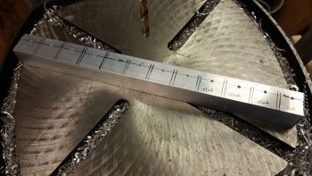
For easier drilling of the holes and the slots, I drilled them all before I cut the U-channel into the respective brackets.  Yes, since I don’t have a mill my slots are pretty sloppy, but for this purpose I’m sure they’ll work fine.
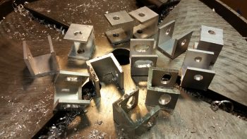
I then cut 12 brackets from the U-channel
And then cut the 3/4″ U-channel into the approximate lengths for the first layer of cross supports.
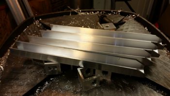
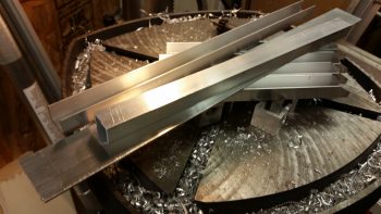
Finally, I cut the 1/16″ x 1-1/2″ aluminum for the micro spreader to 16-1/2″ long.  I also cut 2 longer lengths of the 3/4″ U-channel stock for the top cross supports/handle bases.
I drilled the 4 holes through the U-channel for my bridge sander and mounted the handle base.
And then started the arduous process of cleaning up each bracket.
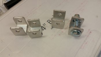
I cleaned up 4 straight-holed brackets and 2 slot brackets for the bridge sander, and left the 6 brackets for the micro spreader for later.
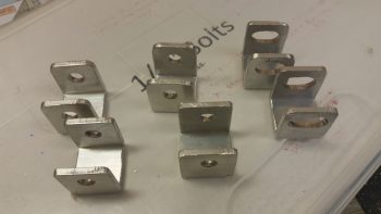
I then mocked it all up to see how it would look.  Not bad!
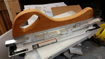
I then drilled a hole in each of the bottom brackets that attach to the base for mounting.  I drilled them just a bit off-center to allow for mounting one countersunk rivet through the base into each bracket to keep the alignment straight.  This was the last action of the evening since I wanted to ponder on the handle a bit.
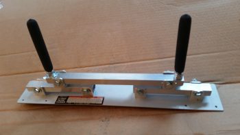
I called it a night, but I couldn’t help but get the feeling that I needed to go with the “traditional” 2-handled setup vs. using the HF sander’s wooden handle.   So this morning I used the handle base/cross support 3/4″ U-channel stock that I had cut for the micro spreader and drilled the final holes into it to allow it to be bolted to the two sander cross supports, and also add two 3/8″ bolts for handles.  I cut about an inch off the top of each handle bolt to allow me to use rubber slip-on grips from McMaster-Carr.

It looked good, but my quick testing of it proved to me that it’s the downward force against the surface being sanded that determines the conformal action of the sanding base, not the actual configuration of the handles.  So my initial hunch was right, and thus I’ll drill up the the base with the wooden handle to see how that works.
I have out-of-town company so the build will be a bit slow over the next few days, but I am happy that I got this reportedly invaluable finishing tool constructed.

 

Chapter 22 – Final Brackets, this time!

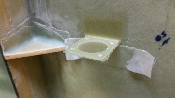
After the BID glass cured on the Throttle Handle electronics cable P4 connector bracket, I pulled the peel ply and razor trimmed the glass.  As I was redrilling the connector mounting holes I set this connector body in place to ensure the spacing was good.

So, here’s the final product for Throttle Handle electronics cable P4 connector bracket.

I then did pretty much the same thing for the Dynon Intercom bracket: pulled peel plied, razor trimmed, redrilled holes and sanded it all to clean it up.  I then set the intercom in place to see how it fit.  I’m definitely happy with how this intercom mounting is turning out so far.

What I’m not happy with is the forward right bracket nutplate.  It’s giving me fits and I’m going to have to drill it out and remount just a hair forward and inboard for it to align correctly with the intercom mounting hole.

Of course the other 3 nutplates went in without any issues, unlike the last one!

Besides redoing the 4th nutplate, I’ll also assess whether or not I need an angled strut at one or either end of the bracket to help support the cantilevered intercom.  I must say that this bracket is amazingly strong, but with vibrations abounding in flight I think I’ll throw on one small corner bracket to bolster it a bit.  It will weigh next to nothing but will add a lot of structural support.


Chapter 22 – More Brackets & RCU

I started off today by razor trimming the bracket for the Throttle handle electrical cable P4 AMP CPC connector.

I did the same thing for the right armrest-mounted Dynon intercom bracket that I just glassed in using 2 plies of BID.  On both of these brackets I was able to knife trim them right at their curing sweet spot, so the glass was definitely more on the cured side, but still just a tad pliable . . .  so it cut well.

I then laid up 2 plies of BID on the bottom side of the Throttle handle electrical cable connector bracket.  I used a small flox fillet in the corner and peel plied the glass junction with the sidewall.

I did pretty much exactly the same thing on the Dynon intercom bracket only for a bit more strength I used 3 plies of glass on the bottom side.

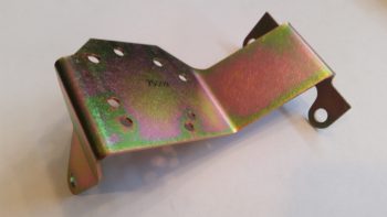
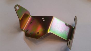
Speaking of brackets, I just received this today so I thought I’d throw it on the blog.  This is the fuel injection spider mounting tab that goes on the top centerline of the engine.  Yet just another item that will go on the shelf for the time being.

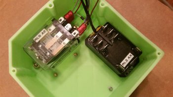
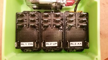
With my bracket glass curing, I started in on mounting the 4 beefy relays into the gear Relay Control Unit (RCU) box . . . fitting name, eh?!  The first relay to go in was the clear cased 3 pole Auto Extension (AE) relay, RL000.  It handles the actual engagement of the gear Auto Extension feature and also is a pass-thru for all the major electrons running the gear up or down.

I ordered this relay specifically with bottom mounting tabs, with the corner of the left tab needed trimmed diagonally just a hair for it to fit properly.   It mounts with a 4-40 screw on each side, each coming in externally from the back.  All the mounting screws coming in from the back side are countersunk to allow the back surface of the box to remain flat, which facilitates ease of mounting the box to the aft side of the Napster bulkhead.

Next relay up to get mounted inside the box was RL003, or the AX relay.  This relay is the one I added back into the mix that charges the small 1.2A backup battery that was provided in Jack Wilhelmson’s original design.  Relay #3 takes control of the system in case of a power emergency to drop the gear down using the 1.2A backup battery for power.  In Marc Zeitlin’s new gear wiring design he doesn’t use this relay since his system incorporates a manual (ratchet) drive for emergency gear extension.

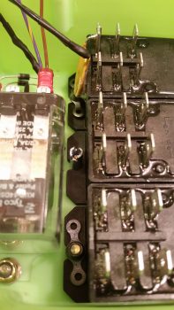
Finally, as for relay #3, I mounted this guy first since it has a unique feature that needed to be dealt with that the other two black relays don’t: down along the top side of the relay is the RXEF-250 wafer style fuse soldered into place that’s used during backup battery charging.  Getting under this fuse to install the K1000-6 nutplate would have been a lot more difficult if I couldn’t get in from the side (where the other two relays sit) to mount the nutplate.  After I mounted this relay, I put some double sided foam sticky tape underneath the wafer style fuse to keep it mounted to the front of the relay for anti-vibration.  I also tipped the box right side up and glopped some E6000 adhesive (yep, the stinky stuff) onto each edge of the fuse to keep it secure to the relay, banned the box outside on the deck for a few hours while it cured and I took off to run some errands.

Upon returning from my errands (which included buying parts for the flexible sander Nick Ugolini describes how to build on his blog) I installed the last two relays: RL001 & RL002 [Note: Simply for space I truncated the relay IDs and labeled them on the actual relays with RL0, RL1 … etc.).  As you can see, these two relays simply control gear up and gear down, respectively.  All went well except for the life of me I couldn’t find a 6th K1000-6 nutplate to use on the top side flange of RL002.  After searching for a good while, and simply not finding the pack of 23 I show having on hand (simply maddening!), in order to get this thing wired up tonight I improvised, adapted and overcame by using an aluminum binder stud, cutting off the top and then quickly Dremeling a not-so-pretty slot for a bladed screwdriver.  I doused it with a good measure of blue Loctite and in it went… Voila!

Here’s another shot of my mounting improvisation . . .

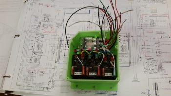
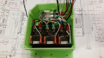
Over the next couple of hours I confirmed & verified the wiring in this box matched exactly what was on the diagram.  Having had to pull all the terminals off their posts, I used a pair of channel lock pliers to compress the terminals just a bit to ensure their clamping pressure was nice and tight.  I then slowly replaced all the terminated wiring back onto the relay posts, performing a continuity check as each set of wires went back in.  After all the wires were back in place, I zip-tied them into place to ensure no wires would be vibrating and wreaking some future electrical havoc by gnawing through a neighboring wire, etc.

Here’s just a closer shot of the internal RCU box wiring . . .

I then cut & terminated all the wires with AMP CPC sockets.  Again, as I finished each wire I performed a continuity check to ensure all was electrical good on that wire circuit from source to connector.

With all the RCU box wiring set to be terminated into the AMP CPC connector, I called it a night.  I may have actually done a bit more but it was quite late and I was collaborating online with Marco (who was in Hawaii for work!) on the specs for the AEM box.


Chapter 22 – RCU Box & Brackets

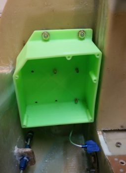
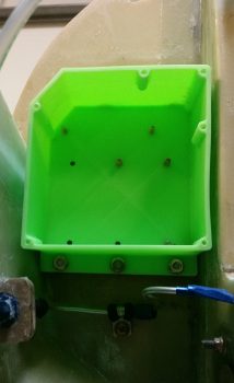
I didn’t get the intermediate steps documented since I’ve been out & about this weekend with friends.  Here is the final result of the Clickbond mounting for the Nose Gear RCU box.  Again, I used 3 plies of BID along the top row (2 Clickbonds) . . .

. . . and 3 plies of BID along the bottom row (3 Clickbonds).  After curing, I pulled the peel ply and cleaned up the goobers.  Thus, the RCU box is officially mounted.
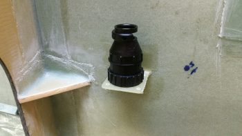
A little sideline tasker I completed was to drill and flox in place this Adel clamp for the Throttle electronics cable that terminates into the P4 Connector.
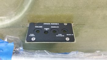
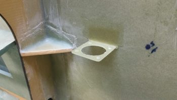
After pre-drilling the 4 screw holes and the 8 holes for the K1000-6 nutplates, I then did a final trim & sanding on the Dynon Intercom bracket.  I determined where its position needed to be and marked the sidewall.  I then 5-min glued the intercom bracket to the sidewall.

I then laid up 2 plies of BID (pre-pregged of course!) on the top side of the intercom bracket, and peel plied it.

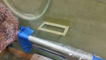
I pretty much followed the same steps for the Throttle handle electronics cable P4 connector bracket just forward of the instrument panel on the left side.  After 5-min glueing it to the wall, I laid up 2-plies of BID and peel plied it.

These tasks above are all on a list of 10 electrically-related items that I want to have finished before I move on to the wheel pants.  Once these brackets and the RCU box wiring are completed, I’ll be down to about a half-dozen items on the list.