Chapter 22 – Electrical system wrap-up

I’ve spent a few hours over the last couple of days updating my Control Stick Switches wiring diagram (#14) which institutes a major redesign on my control stick switchology. This is of course is the first draft with all the foundational components in place.  It still needs much refining.  For example, I still need to design & emplace a switch into the mix that will allow me to disable the GIB control stick switches for those times when I’m hauling kids (or Marco!) in the back, who may be just a tad too inquisitive and want to get handsy with the buttons! (sorry for the poor pic quality…)
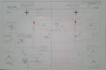
Stick grips switch wiring

I would say one of the big electrical system breakthroughs I achieved over the past week is taking the stock ON-NONE-(ON) toggle switch located just to the left of the china hat switch on the Infinity stick grip, and making it work to suite my design goals.  I wanted it to control my COM1 ↔ COM2 radio swap [COM1 = Garmin GTN650 & COM2 = GRT HXr EFIS-controlled Trig TY-91] and wasn’t past swapping out this switch if I needed to, but I definitely wanted to make it work if possible.  In my monkey brain I intuitively “knew” when I bought these sticks from JD that I should be able to design what I wanted circuit-wise.

With that extra momentary ON position when the switch is toggled aft, I wanted a way to use that switch for controlling the frequency flip-flop for BOTH radios, as well as the COM1 ↔ COM2 radio swap.  This is where digging into the installation manuals and discussing with GRT really helped, since there is no remote freq flipflop feature on the GRT HXr (this is accomplished with a button on the right side of the EFIS).  Since the inherent features of the GRT HXr EFIS removed the remote freq flip-flop feature off this switch’s ‘to-do’ list, I was then left with my COM1 ↔ COM2 radio swap requirement, plus controlling ONLY the COM1 freq flip-flop.
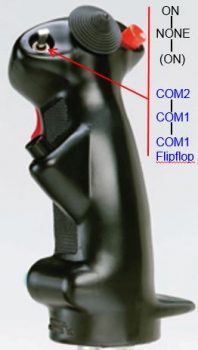
Infinity Stick Switch

As a point of clarification, remember that Garmin doesn’t allow third-party vendors (AKA GRT) to remotely control their radio functionality through a separate component like an EFIS (yes, there are remote functions via switches/buttons and some SL30/SL40 command features, but not full control of the GT650/GNS430 communications functions). Thus, my setup is the Garmin GTN650 (COM1) as a separate radio controlled totally outside of the GRT realm, and then a remote Trig TY-91 transceiver (COM2) controlled via the GRT HXr EFIS.  The sound and headset features of both of these radios are controlled via a Dynon Intercom.  It is the COM1, COM2 select feature of the Dynon Intercom that the stick mounted toggle is controlling.  The COM1 freq flip-flop is wired directly to the GTN650.

Utilizing a relay, my design functions such that COM1 is always the default com radio unless the switch is pushed forward, thus driving the relay switch off the N/C (normally closed) COM1 side to the N/O (normally open) COM2 position.  Since I control the COM2 radio freq flip-flop on the EFIS there’s no issue with not having the COM2 flip-flop feature on the stick toggle. Obviously, in the default COM1 position –which I’ll be using 80-90% of the time– engaging the toggle switch in the MOMentary down position has no effect on COM1 ↔ COM2 radio selection.

Ok, so I’m extremely pleased with this setup since it perfectly matches the capabilities of my planned panel components.  One issue resolved, 287 more to go . . . . ha!

In the pic below you can see my inventory and ID’ing ALL the switches I have on hand. Since I had some extra switches that I got from JD when I bought the Infinity stick grips, I was checking out the weight of the larger Carling (B&C) switches vs the smaller toggles. If you’re curious: 3 B&C switches weigh around 0.18 lbs vs. 3 mini-toggles weigh about 0.04 lbs.  As you can see, I am reassessing my panel switchology and trying to attain some weight savings where I can.  I will say that using mini-toggles adds time and complexity to the electrical system build since those switches must be soldered in vs the nice FastOn connector tabs incorporated on the B&C switches.
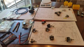
Switch inventory & planning

I also knocked out some of the more background tasks for both the electrical system and in prep for getting back to the build.  I made a run to Harbor Freight and stocked up on some supplies.  And as I was out and about I got a battery for my ever-trusty & ever-present epoxy-laden build WATCH, and got it back online.  And I stopped by FedEx to buy a long 12 ft length of 48″ high plotter paper to lay out and start designing my wiring harness in real dimensions, later on when time allows.

Finally, I spent about 3 hours last night finding/researching/purchasing replacement mini toggle switches, and submitting a decent-sized order with Mouser.  These orders bring me current for all the outstanding bits & pieces (resistors, relays, AMP CPC connector, switches, pins, sockets, etc.) that I need up to this point for my electrical system build.

From here, I plan on finalizing the design and update on my stick wiring diagram and then I’ll transition into focusing on the real build stuff!
 

Chapter 22 – Electrons come from paper!
Ok, so as I mentioned in my update, I have been working on my electrical system . . . a lot! I’ve probably put in a good 30 hours on my electrical system over the past 3-5 days.

Why, you ask?!  Especially when the plane is not near the point that it needs such detailed electrical diagrams!  Well . . .  I’d argue otherwise.  Having finally got my other house off my plate –it closed last week!– I am getting ready to do another gargantuan push on the build. I have no other real detractors at this point and I am preparing to dive in with all I’ve got. So, besides simply wanting to clear up a few nagging issues in my electrical design, especially before bringing any more on board, I wanted to get my electrical system design and documentation as up to speed as possible.

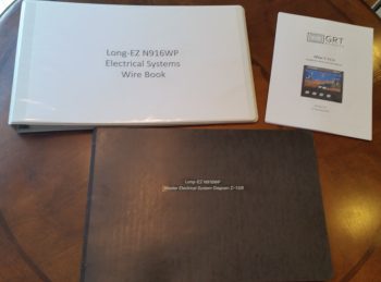
Below is the end result of my efforts over the last few days.

Wire diagram books

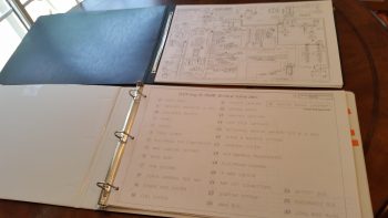
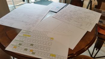
Here are the individual diagram pages for each subsystem.  To be clear, these are ONLY the ones that I’ve updated over the past week!  There are still about 10 more that need to be tweaked, refined and updated.

Updated Electrical Diagrams

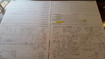
An even closer shot . . .

Updated wire book pages

My focusing on the electrical system was some what of a result of 3 things converging on me at once.

First, my buddy Marco bought a beautiful Long-EZ to fly while he finishes up his build. Stemming from discussions on his new plane, our in-depth mind-melding on switchology, control/switch ergonomics and safety really got me diving deeper into a topic that I had been bantering around in my mind for quite some time.

Next, Grand Rapids Technologies debuted their 8.4″ HXr EFIS at Sun ‘N Fun in April. DONE!!!!!!  This is exactly what I have been waiting for FOR YEARS!!!  The right size with the right features to drive my components in meeting my design goals.  With this in hand, combined with a much more refined picture of my switchology, I set forth to conquer any of the major remaining design daemons in my architecture.

Lastly, I’m just bone tired.  I had less than a week to clean a very messy house that my tenants left me, and I had a number of repairs on top of that. I was working 13-16 hour days for almost a week, and I am just exhausted.  Working on the electrical system lets me rest a little physically as I recharge to tackle this beast!  Hoo-ah!

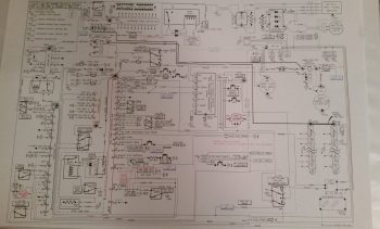
(Below is a pic of my Master Electrical System Diagram, which has been modified over a dozen times in the past month alone!)

Master Electrical Diagram

Over the past couple of days I’ve been on the phone with EFII, GRT, B&C, Trio, TCW, and a few others confirming my architecture design in the areas that incorporate their respective products.  I also confirmed some key system design features in a discussion with Bob Nuckolls (author of The AeroElectric Connection).  In short, I’ve been able to clear up a number of nagging design issues, streamline my system and really make a number of my electrical design goals a reality… There are a lot of them, so I’ll discuss them individually in-depth as I incorporate them into the build.

Electrical Docs

Freshly made wire books!Finally, I think I mentioned before that I took a bit of time to really go through my documentation on hand and clear out all the junk, archive most of the gee-whiz stuff and get it fairly organized into binders and work folders.  I had the same idea for my electrical system design documents as well, considering I haven’t really had any of them consolidated into a meaningful system until today.  I finally took the time to build electrical system binders to incorporate ALL the electrical system wire books, system diagrams, etc. into 2 binders, shown above, and I even constructed a table of contents/index.  I have to say by the time I was done I felt a huge sense of relief knowing that my electrical system is looking really, really good as I head into one of the final build surges on my Long-EZ project!


Chapter 21 – Fuel Pump Fittings

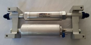
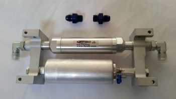
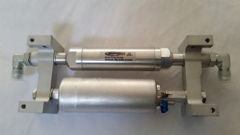
I finally knocked another item off my list  by giving the folks at EFII a call to order a couple of 90° fittings.  Unlike standard right angle fittings, these 90° fittings supplied by EFII can be clocked into any orientation so the exact angle of the connected fuel lines can be dialed in.

Fuel pump

I need these right-angle fittings since I’ll be placing the fuel pump in the hell hole mounted on the underside of the CS spar.  The awesome folks at EFII quickly sent me out a pair of the 90° fittings with the only requirement that I send back the stock straight fittings.

Fuel pump

Here’s my newly configured fuel pump, now ready for install!

Fuel pump

Chapter 22 – Trio Pro Pilot on deck!

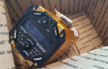
Today I finally received one of my instrument panel items that I’ve had on the list of things to buy for years now!  About a week ago I pulled the trigger on the Trio Pro Pilot Autopilot control head.  If you recall, I bought the servos from a guy off of eBay a couple of years ago and had them sent straight to Chuck at Trio who upgraded and ops checked them to ensure all was good.

LEZ Trio Propilot

This autopilot unit has the GPS Steering (GPSS) and GPS Vertical Steering (GPSV) options on it, with the GPSS allowing the Pro Pilot to receive GPSS commands from the GRT EFIS or Garmin via ARINC 429 data outputs.  The GPSV allows the autopilot to receive pitch steering commands from a WAAS GPS receiver for precision approaches using GPS.

In addition, after a lot of discussion over the years, Chuck tweaked one of the pull up resistors in this Pro Pilot’s innards so that it can receive fuel data from the FT-60 Red Cube fuel flow meter along with the GRT EFIS.  This gives me fuel management on both the EFIS and the Pro Pilot, which provides some pretty nifty fuel flow information.


Chapter 22 – Securing Main Battery

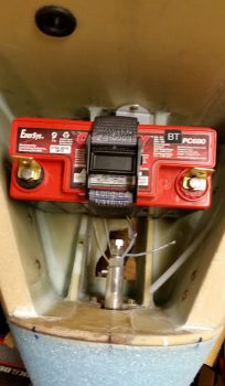
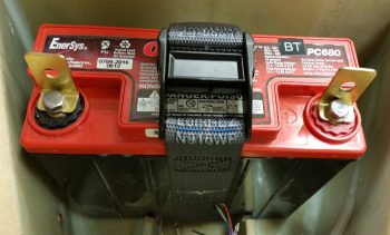
Today I received my custom battery straps to secure the main battery in the battery compartment.  The strap and buckle are military grade that will easily hold a 15-pound battery in place.

Custom Battery STraps

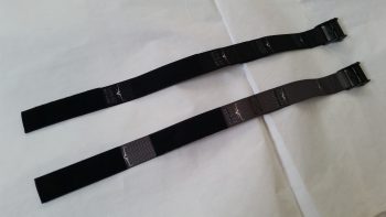
Since the main cost was for prototyping up the first strap, I went ahead and ordered a second one in black.

Custom Battery STraps

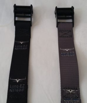
I got these from Strapworks out of Oregon, and for the most part I’m pleased with them.  I will say however that I think they could have done a little better job with the placement of the images, which for some reason seemed to be quite the challenge for them.  Oh well, a minor issue in the grand scheme of things!


Chapter 13 – Grazing & Raising!

Today was quite the beautiful day here in Northern Virginia, so after messing around with my school work for a couple of hours, getting my motorcycle battery charged up enough to get it started and out for a quick scoot, and then spending just over an hour on the phone with my building nemesis Marco (ha!)…. I finally got into the shop!

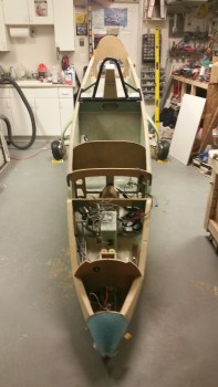
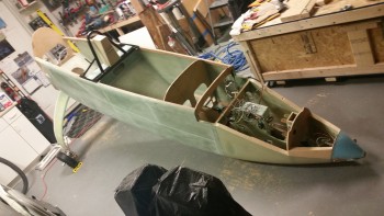
My main goal for this afternoon was to get the fuselage off the dolly and into its grazing stance, which I did as you can see below.  Before I actually offloaded the fuselage from the fuselage dolly, I did a bit of Spring cleaning in the shop and attached the rollbar and headrest to the fuselage.

Fuselage in grazing position

My next task was to install the battery in the nose and connect up the wiring leads to get the nose gear to extend and finally get this bird on all 3 wheels!

Fuselage in grazing position

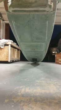
First, I wanted to get a couple of shots of my grazing fuselage from the aft end.

Fuselage in grazing position

Especially this shot, where the nose is fully resting on the nose bumper, which of course is the aerodynamically clean shaped nose bumper that my buddy Marco CNC’d out of a hockey puck.  He did a fantastic job on it!

Fuselage in grazing position

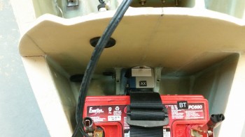
I then got the battery installed into the nose battery compartment and the power cables clamped into place.  Note in the pic below you can see the nose gear backup battery immediately aft of the main battery.

Nose battery compartment

I shot a video that covers the majority of work I’ve completed over the last few months. Then, at the end of the video, I raise the nose by extending the nose gear for the first time during this build.  Note that I merely strapped in the battery, attached the leads, and then shot the video.  There was no previous testing to ensure it worked and the initial nose raising in the video is just that, the initial nose raising in real time.  I’m just glad it worked! Whew!

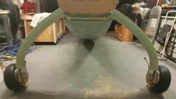
I took one final pic of the fuselage on all 3 wheels before closing up shop for the evening. This of course is another huge milestone for this build!

Ready for taxi!

Over the next few days I’ll be doing a final check on the wheels to ensure the toe-in is correct and set for one final time!  In addition, I’ll also be prepping for installing the wheel pants.


Chapter 9 – Flaring tool & heat shields

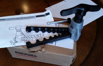
First off, UPS delivered my Ridgid 37° flaring tool yesterday morning.  This tool will enable me to flare my 3/16″ stainless steel brake tubing, thus allowing the final pieces to placed into the brake line system.  Now, this tool’s specs does not specifically state that it’s rated for stainless steel, but many of the reviewers on Amazon did clearly state that they used it with very good results on stainless steel.  So I figured I would give it a try.  I will tell you that it is much bigger than it looks in the pics, and this thing is a heavy, robust beast.

Ridgid flaring tool

Secondly, I’ve been doing a fair amount of research on my toe-in dilemma and I’ve decided to pull the wheels, configure the fuselage upright without the fuselage dolly in the way and do one final toe-in setting to get them to specs.  After reviewing both the plans, what other canardians have done, and even the standard on other types of aircraft, I’m concerned my toe-in is too much, even for a heavier than plans bird.  I would probably not mess around with it if it were, say, 0.5″ total vs. the 0.45″ total called out for in the plans, but I’m significantly over at 0.6+”.

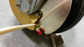
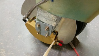
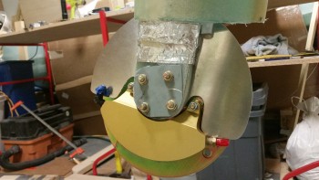
Finally, I’ve been updating my to-do task list and one thing I forgot to add came up today when I took a couple of pics to send to Marco earlier.  I was pointing out how the aft tab of my right heat shield was just barely kissing the brake caliper… as I’m pointing to in the pics below.  I’ll trim about 0.1″ off that area when I remove the wheels (AGAIN!) to set the final toe-in.

Heat shield interference

Heat shield interference

As you can see, the left side heat shield clearance is fine.

Left side heat shield clearance good

This morning I got an order from McMaster-Carr with my 1-1/2″ stainless steel cap head screws to replace the 1″ screws Marco had included with the nose bumper.  Since I had to install the nose “Exoskeleton” over the 1/4″ thick 2024 aluminum skid plate that has K1000-4 nutplates riveted to the back side of it . . . well, clearly I needed longer bolts.  This makes today the first time that my nose bumper has been officially mounted on the lower nose!

Nose bumper permanently mounted

As for the build, I’ve clearly not been in the shop much lately.  This is due primarily to my Commercial Pilot Rating ground school which, to be honest, is kicking my butt as far as the amount of time required to complete the course work.  I’m trying to get ahead of the power curve, but then I fear once I start flying, the pace will only worsen.  We shall see.  I do honestly believe that once I can stop playing catch up and get into a good battle rhythm, that more work will get done on the plane build.


Chapter 9 – Wheels on ground!

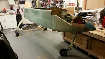
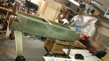
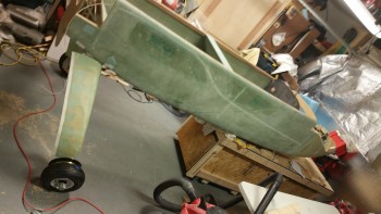
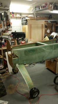
Tonight was a milestone in that it was the first time the fuselage has rested on the main wheels … ever!

I lowered the fuselage dolly platform to get the fuselage as low as possible to slide it aft on the fuselage dolly and thus get the main gear wheels on the floor.

Setting main wheels on the deck

Forgive the camera angles, but I was backed up all the way in the corner and trying to get as wide angle of a shot as I could!

Main wheels on the deck

After I got the fuselage set so I could access the CL on the belly, I started attaching straight edges, running strings and plumb bobs, etc. to double check the toe-in on each side.  As I suspected, I jacked up the toe-in pretty good after I had set them correctly from the first go around with the gear in the air.

When I flipped the fuselage over I had double-checked the toe-in and it seemed to be either negative (wheels pointing out) or not enough.  So when I mounted the wheels I sanded down the mounting pads to reset the toe-ins correctly.  Of course, as often is the case, I should have left well enough alone!

Fuselage on main gear wheels

With access to the CL mark on the belly this evening, I could actually determine the CL to double check my toe-in measurements.  After it was all said & done this evening, I confirmed that my left wheel assembly is mounted approximately .08″ farther outboard than my right, which is not enough for me to worry about any further.

However, my toe-in is much more than it technically should be with each side a hair over 0.3″.  I figure that per plans the max you want to be at is 0.45″ combined, and I’m sitting just under 0.65″ combined.  However, since my plane will have a bigger engine and weigh a couple hundred pounds more than what Burt was originally planning these birds to weigh in at, I’m not going to make something not-so-great even worse by mucking about with it.  At least not right now.  I’ll wait until I do my high speed taxi tests to see how my tire wear is progressing & then adjust fire from there.

Tomorrow I’ll get the fuselage dolly out from under the front of the fuselage, lower the nose gear and play around with that a bit and grab some pics for prosperity sake.  I’ll then start working on prepping the wheel pants for install.


Chapter 9 – Wheels Installed

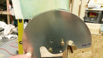
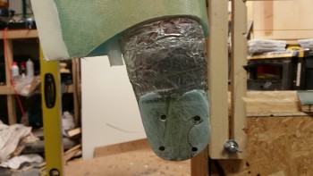
I started off today by test fitting the right heat shield onto the gear leg.   The foam of the lower gear fairing extended out enough to make it impossible to mount the heat shield in its correct position.

Test mounting right heat shield

I marked the perimeter of the heat shield onto the lower gear leg in preparation to cut the glass & foam away from the lower gear leg.

Right heat shield gear leg notch marked

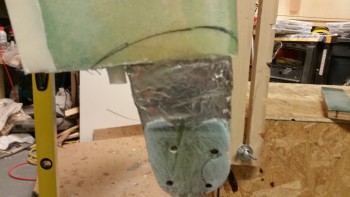
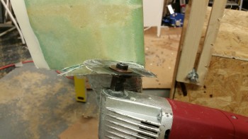
I then used the Fein saw to cut away the glass & foam away from the lower gear leg to allow the heat shield to fit correctly in place.

Cutting right heat shield gear leg notch

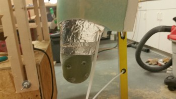
Here’s a shot of the trimmed lower right gear leg.

Right heat shield gear leg notch cut

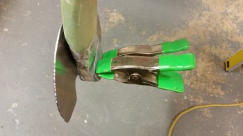
I then remounted the right gear heat shield, which fit fine.  I held the AN4-22A bolts in place with spring clamps.

Test mounting right heat shield again

I then repeated this process on the left side to clear the lower gear leg glass & foam (and micro) to allow the left heat shield to fit correctly.

Left heat shield gear leg notch cut

I ran a line down the fuselage CL to double check the toe-in, and even sanded the gear axle mount pads, but after dialing them in as best I could I realized that I was about as close as I was going to get at this point.  I’ll do some final checks with the fuselage actually sitting on the ground.

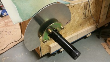
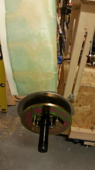
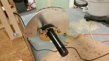
After messing about with the toe-in and dialing it in as best possible, I then mounted the axle, brake mount assembly and the heat shield onto the right gear leg.

Mounting right axle & heat shield

I then mounted the right brake rotor and brake caliper assembly.

Mounting right brake assembly

Here’s an inside view of the right brake caliper assembly.

Inside right gear brake assembly

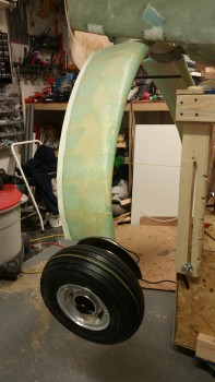
I then installed the wheel & tire onto the right side gear leg.

Right wheel & tire installed

Here’s another shot of the right wheel installed.

Right wheel & tire installed

After installed the right wheel, I installed the left axle, heat shield and brake mount assembly.  Unfortunately, after tightening up all the nuts on the AN4-22A bolts and then attempting to mount the rotor & brake caliper assembly I realized that I had mounted the brake mount assembly upside down… doh!

Left brake mount installed incorrectly

This is how it should look!

Left axle & heat shield installed (

I then mounted the left brake rotor & brake caliper assembly.

Left brake rotor & assembly installed

Left brake rotor & assembly installed

Here is a shot that I’ve been wanting to take for a long time: both wheels mounted!

Wheel assemblies installed

I then mounted the 9.5″ braided stainless steel Stratoflex brake lines that will connect the brake caliper to the stainless steel brake line tubing.

Right stainless steel brake line installed

Here’s an inside view of the right (top) and left (bottom) braided stainless steel Stratoflex brake lines.

Right stainless steel brake line installed

Left stainless steel brake line installed

I then mounted the wheel axle nut sleeves to both Matco axles. These are sold by Van’s Aircraft for mounting the outboard side of the wheel pants.

Van's threaded wheel pant axle mount

With the gear fairings finished and the wheels now mounted, I will start the process of installing the wheel pants.  After I get the wheel pants installed, I’ll then flip the fuselage back over, finalize installing the brake lines.  Finally, I’ll then work on the RAM air scoop and aft fuselage extension over the hell hole area.