Chapter 9 – Executive decision!

I started off today doing hours of research on the wheel pants installation.  I’m not sure what happened, but I compiled a bunch of info on wheel pants in a PowerPoint slide deck earlier this year and couldn’t find the darn thing!  I did go back and review Wayne Hick’s sage advice on his phenomenal web page: Chapter 9: Wheelpants and also Bernie Siu’s, Nate Mullins’, and Joe Coraggio’s sites for wheel pants install info.  I compiled a bunch of it into a doc and printed it off as my “Everything you needed to know about installing wheel pants” guide!

In fact, while reviewing Nate & Joe’s adventures on their recent (respective) finished flying Long-EZs it was then that I made the decision NOT to move forward with a full-on install of the wheel pants.  Why? Well, after a fair number of high-speed taxi tests and numerous landings both Nate & Joe have had significant tire wear issues.  Keeping Nate & Joe’s experiences in mind, I figure at some point I may very well need to modify the wheels’ camber in addition to possibly having to modify the toe-in.  If those issues do play out, then having hard mounted wheel pants would require a significant rework of the wheel pants.  Taking all this into account, I simply don’t feel that it’s prudent to move forward with the actual full-on wheel pants install.  However, I do want to lean far forward and be as prepared as possible when I do go to install the wheel pants so that the installation will be optimized, smooth and quick.

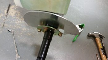
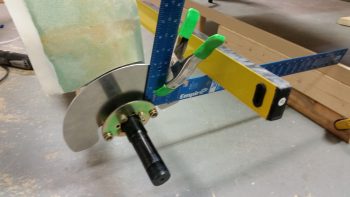
As I’ve stated before, I’ll be using the Vans axle nut that has a K1000-4 nutplate installed in the end of it specifically for mounting wheel pants.

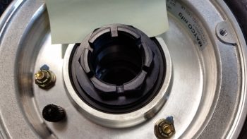
Marco's original axle nut

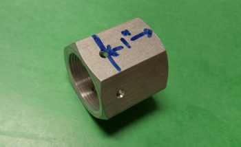
As you can see in the pic above, the Matco axle nut has essentially a built-in washer at its base.  Thus, I cannot simply use the Vans axle nut as a replacement for the Matco axle nut (which it was designed to do).  If you look at Bernie Siu’s website you’ll see that the Matco wheels that he and Wayne use incorporate a separate washer underneath the axle nut, unlike my wheels.  The separate parts enabled Bernie to machine a lip on the Vans axle nut to keep the washer centered. Again,as you can see above, my version of the Matco wheel does not have a separate axle washer and nut, so doing what Bernie did is simply not an option.  However, cutting the Vans axle nut shorter to only 1″ in length (pic below), will allow me to mount the Vans axle nut over the Matco axle nut in the same manner that Wayne Hicks did.

Van's Matco axle nut extensionWhile I had all the parts in front of me, I measured the tire valve stem distance from axle center line to locate a good mounting position for the spring-loaded valve stem hatch.

Measuring valve stem from wheel CL

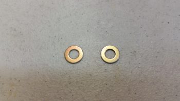
In pondering how to fix the Right side toe-in that points inboard just a tad too far, I considered using AN960-416L washers as shims on the forward axle bolts to kick the toe-in back out.

Hmmm? Possible shims?

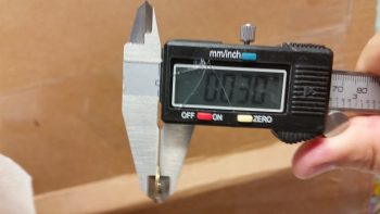
But that turned out to be a no-go, since these washers are a 0.030″ thick.  That would equate to over 0.3″ back outboard at the 24″ forward (of the axle) mark, in effect creating a toe-out vs. toe-in!  So I did the math and concluded that I actually need a 0.007″ shim, which would result in the right wheel’s toe-in very closely matching the left.

Uh, nope! Not gonna work!

I removed the Right side axle bolts in prep for eventually installing shims on the forward 2 bolts.  In addition, I’m going to swap out the longer axle bolts for slightly shorter ones.

Prepping for shims & new bolts

Another piece of information that I serendipitously discovered today concerns my instrument panel.  The other day when I cleaning up the shop I ran across the sheet of 0.090″ 6061-T6 aluminum that I used for the heat shields.  I quickly measured the instrument panel to see if I could use the remainder of this 6061 piece for the instrument panel (there’s enough), since it just seemed like a good thickness for the panel.  Well, lo & behold as I was researching wheel pants today, I saw on Nick Ugolini’s site the he specifically recommends using 0.090″ 6061-T6 aluminum for making an instrument panel!  Sold!  Say no more Nick, I will comply!!

Ok, finally, just as a historical record, I also filled up the nose wheel tire with air!

Tomorrow, I’ll be prepping the wheel pants and hopefully getting the first initial steps in to widen them by the 1″ I decided to widen them.  As I stated before, I’ll be getting all possible tasks on the wheel pants completed up to the point of actual install.


Chapter 9 – Main Gear Enigma

I started out today by updating my Master Project Build Schedule which I call my “Order of Battle.”  I figured I need to start with the master schedule to better detail what tasks that I am specifically going to do on my Chapter 9 To-Do sheet.  In doing so, I broke out the hell hole cover and RAM air scoop for a later date after other prerequisite tasks are completed.

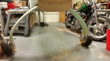
I then set about to figure out this pesky toe-in issue that needs finalized.  I put the fuselage up on a fold out table vs. fuselage dolly so that I could get a clear shot of the CL & the front gear leg.

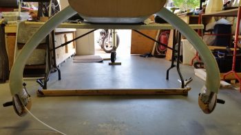
I started by leveling the longerons side-to-side.  I also clamped a board onto the table legs perpendicular to the fuselage and then positioned the fuselage so that the axles were set back from this board 24″.

On the table

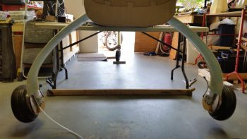
I then removed the wheels/tires, brake disks and pads off of each axle.

Wheels removed

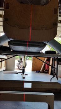
At this point I needed to find the aircraft CL, so I shot a laser line which allowed me to check the toe-in of each wheel not just in comparison to each other, but to the CL as well. I took the pic below a little off center, that’s why the line seems a bit askew.

Marking centerline

I then clamped a 24″ square to each side and checked the toe-in.  The plans say that the max toe in delta between the “B” measurement (at the axles, or 0 inches) and the “A” measurement (at 24″ forward of the axles) should be between 0.2 and 0.45 inches.  Right now, I’m sitting at 0.62 inches, with my right wheel toed-in 0.08″ more than my left.  If I can get the right wheel toe-in the same as the left, then at 0.54″ I’ll be happy and call it a day.  This may be a bit more than Burt called for in the plans, but then again, my aircraft weight is a bit more than what Burt advised as well.  One other thought is that I’m not going to jump through a lot of hoops now until I start doing some high speed taxi tests & a few landings, at which point I’ll tweak what needs tweaking!

Checking toe-in

Now, a few more figures.  Before I took the wheels off I measured from the front center of each tire near the ground to the large nut on the nose wheel fork.  Each side came out very close to 110″.  Then, after I removed the wheels I also measured from the bottom of each axle to the 6-foot level I had across the longerons, with each side measuring close to exactly 48.5 inches.  I then measured from the aft side of each of the inside, top-forward axle mounting bolt to the fuselage CL at the back edge of the fuselage bottom: Right side 34.32″ and left side 34.25″.  I also checked the dip angle of each axle hanging free, both came out to 12.4°.  Finally, with the longerons level I laid the long level across the squares as close to the gear legs as possible: perfectly level as well!

So . . .

Interestingly, when I checked the distance between the end of each axle, straight out perpendicular to the fuselage, I kept coming up with the left side axle end being 0.7″ closer to the fuselage than the right side!  I did this a number of times, in a number of different fashions, and each time it told the same story.  Very odd!  The only correlating data that helps support this –that I didn’t mention above– is that through my “A” & “B” measurements for the toe-in, I again measured that my left AXLE is 0.33″ closer to the centerline than is my right.  This actually makes some sense, because I mistakenly added nearly 0.2″ more BID to the right side gear leg due to my misID’ing the CL when the fuselage was upside down and I read the wrong mark on the freshly extended firewall.

My conclusion is that I MAY add a spacer to help clean some of this up.  I talked to my buddy Marco and he advised to leave it and press on (good advice), but a big factor in this decision will be the affect it has on the asymmetry between the wheel pants.  I’ll being doing a fair number of measurements tomorrow on those in prep of installing the wheel pants.  In short, more to follow on this.

In other news, I was able to trim the offending right heat shield on the aft side where it was barely touching the brake caliper (actually visible in last pic above).  I also topped off the tire pressure raising it to the recommended 70 PSI from the 50 PSI I had filled them up to (actually, after 6 months, both tires were down to 30 PSI each).

Shop is back online!

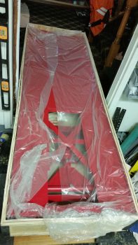
Alright….Finally!  Today’s major push was getting the motorcycle lift —that I picked up CHEAP at Harbor Freight for my custom motorcycle project (that gets finished after this airplane!)— out from under the fuselage and into the room just behind the garage.  A room that once served as a billiards hall that now is a parts predeployment & storage facility… did I mention I want to get this bird finished and out of my house!  ha!

(sorry for the blurry pic)

Blurry Pic

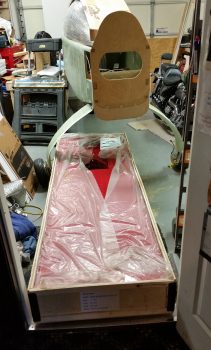
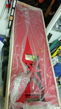
Apparently the gods favored me this day because when I measured the width of the motorcycle lift crate it was 29″ wide.  The doorframe leading into the house surprisingly was over 30″.  Could it be this EZ?  Well, besides this thing weighing a LOT, it was fairly EZ.  Especially since I had it on 2 furniture mover dollies.

Moving bike lift out!

When I took my big behemoth Eaton compressor out of my other house to store it at a friend’s house, I had bought 2 more furniture dollies to mount it on to make it mobile.  Since I just recently sold that compressor, I was able to reclaim those furniture dollies, which came in real handy here. I simply slid the motorcycle lift through the door and off the garage dollies onto the set of dollies inside the house.

Moving bike lift out!

It took around 30 minutes total, but I got this beast moved!

Moving bike lift out!

It’s nice to have my shop floor back (to an extent) and be able to freely move the fuselage around.

Ahhh, working space!

Obviously, it’s still a bit tighter quarters than I prefer, but hey, it beats the micro-garage I was working in while in Germany!  So alles ist gut!

Time to get to work!

The Push Continues . . .

I am very close to starting back on the build, although it is quite amazing to me how much extraneous junk that I’ve had to contend with from selling my other house.  Dealing with this has been the long tent in the pole preventing me from getting back on the build.  And having been in a full-on repair blitz during the time leading up to the house actually closing, I’m just now really get all the tools & materials sorted out, organized, and put back into their proper places.  Additionally, during the last week I have been doing some odd & end stuff on the build, much of it stuff I was never able to really put together before since I didn’t have all the pieces parts in the same location.  As I’ve been getting my shop and house in order to build, I’ve also been focused on prepping –at least mentally & planning wise– for some other parts of the build. So, here we go.

Canopy Latch: A note that I’ve had for a while in the middle of my electrical switch diagram states to account for the panel space required by the canopy latch arm that sticks out horizontally into the space near the throttle handle.  I became acutely aware of how much space the canopy latch was really taking up when I sat in my buddy Marco’s Long-EZ specifically to note clearances, required reach to cockpit items/switches, and simple ergonomics.  It emphasized that the note on my switch diagram truly had merit, and that I must indeed account for this most necessary but intrusive component.

Thus, back at my hacienda, I finally got around to pulling out the EZ-Rotary Canopy Latch kit that I bought from Jack Wilhelmson (eznoselift.com).  I first (re-)inventoried all the parts to ensure I hadn’t lost anything over the years.  I then did a quick (re-)review of the installation procedures to get a feel of what I was up against.   My main current concern was of course the clearance with the instrument panel, and luckily with this setup the bearing block hangs down from underneath the longeron, and not straight out from the panel, thus giving me back the 3-4 square inches that I wouldn’t have been able to use on my instrument panel if I had installed the plans version of the canopy latch (pic below is from Jack’s website).
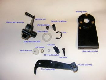
EZ-Rotary Canopy Latch

Electrical System:  Ah, yes, this beast keeps rearing its head.  Yes, yes, I am very close to a final system configuration, at least for now.  But stuff is still cropping up!  I equate it to trying to get all the dish soap out of a sponge: every time you squeeze it more soap comes out again!  So . . .

Pitot Tube Electronics & Components: Starting back in the beginning of 2013, my buddy Marco and I started brainstorming on a heated pitot tube design for our Long-EZs. Recently, Marco has been doing some truly amazing work on the electronics that drives the pitot tube heat.  In preparation for the electrical components that he’s developed for the pitot tube, I recently purchased another airspeed switch, and a new 3-position ON/OFF switch that has a momentary ON position in the farthest up point to reset the electronics if need be.  Marco has been detailing a lot of this on his phenomenal blog, What have I gotten myself into!

Control Stick Button Role Refinement & Swap: While down in Virginia Beach getting my first Long-EZ ride from my Marco, he at one point recommended that I swap my alarm momentary shutoff (left side of stick) with my A/P disengage & Pilot Controlled Steering (PCS) button (upper right of stick) on my control stick.  Well, I have to admit that I was a little resistant at first, but after pondering the idea and getting into the Trio Avionics Autopilot manual (and really finding out the advantages of using PCS), I actually had an epiphany while driving home one evening: since the top right button is the hardest to reach on the stick, then why not use it to control something that I will use very occasionally in the air, and almost exclusively on the ground.  Whereas with my new found understanding of PCS, I am confident that I will use that much more while flying.  Thus, I wanted the A/P button in a much more user friendly place on the stick, so of course I swapped them… which is simply code for I changed the CAD drawings for both the buttons’ electrical wiring connections.  Nonetheless, thanks again Marco for setting me straight!  ha!

Here’s a pic identifying my current Infinity control stick button & switch assignments.
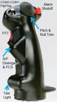
Infinity Stick Switch Assignments

AG6 Warning Annunciator (#2): As I was getting a bunch of these ‘final’ items squared away before jumping headlong back into my build, I submitted parts orders with B&C, Mouser & Aircraft Spruce.  Part of my order with Mouser was a direct result of my discussion with Rich from AircraftExtras.com, who gave me a bunch of great info on the AG6 warning annunciator.  To drive a myriad of warnings that would normally require an LED on the panel, I ended up calling a number of vendors to confirm the correct resistor values & wiring circuitry to use with their specific products.  Once I had the recommended resistor values in hand, I fired off an order to Mouser for all of them.  That also helped me to finalize which of my components would/could utilize the AG6 to annunciate an alarm condition.  One thing was certainly clear after I figured out what-was-going-where for my alarm annunciations, and that was that I didn’t have enough “where” to go to!  I needed another AG6 to handle the increased number of components connected to the AG6(s) to annunciate their alarm conditions, so I ordered a second one.
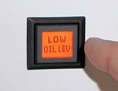
AG6 Warning Annunciator

The missing 2-Amp Circuit Breaker!  One day last week as I was updating my electrical system diagrams I ran across the 2-Amp inline fuse for the SD-8 backup alternator activation switch on the circuit diagram.  As I was assessing that switch specifically, for some reason the inline fuse didn’t seam like the right fit.  I pulled up the B&C install manual and sure enough it showed a 2-Amp circuit breaker, NOT an inline fuse! I then went back through the last couple of versions of Bob Nuckoll’s Z-13/8 system architecture diagrams and…NO inline fuse!  “Huh?!” sez I, “Where did I get the idea for placing a 2-amp inline fuse there?”  Well, I finally found it in an old version of the system diagram that I had started with back in 2012! I guess it pays to review, or, well, it actually costs money since I had shell out some more to buy a 2-Amp Circuit Breaker.  Regardless, I’m just glad I found my oversight & corrected it ‘early’ on.  By the way, this scenario is exactly why I’ve been critically assessing literally every component in my electrical system!

Engine Cowling Installation:  Over the past few days I also wanted to get a lot smarter on exactly how the upper & lower engine cowlings would be mounted, specifically the hardware to do so.  This meant getting much smarter on Camlocs and the Skybolt Croc system.  I researched a fair bit and bought a few basic Camloc components in my last Aircraft Spruce order to test them out. In addition, I’ll be using Mike Melvill’s 82° stainless steel hex-drive screws that he discussed in the Canard Pusher newsletter (CP 73).
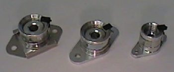
Skybolt Adjustable Receptacles

Electrical & Aircraft Component Weight:  Upon receiving the new 2 amp circuit breaker and AG6 warning annunciator I decided it was time to spend a good hour to update my estimated aircraft weight worksheet.  I added all the new components, eliminated old ones, and weighed a number of components that until previously I only had factory listed or estimated placeholders for.  When I finished, my Long-EZ had gained 10 lbs, with its new estimated weight still just under my max goal weight of 1,000 lbs… but just barely! And by barely I mean less than a pound under.  The good news is that I have a lot better idea of what is going into my airplane and now have hard weight data vs. estimated/unknown data variables.  Obviously, since I now have a lot of this stuff on hand, I can get the actual weight of each item.  Moreover, I have padding built into the weigh figures for the electrical system, avionics/equipment, and main airframe components.  Thus, I suspect to be somewhere near 1,000 lbs. for my final weight, ± about 30 lbs. (yes, yes, more likely plus than minus!)

Integrated Backup Battery System (IBBS) model selection:  One thing that I did in the planning of my future components order is to mock up the fit of my TCW Technologies IBBS in the nose where I plan to install it.  After a discussion with Marco on the W&B on his new Long-EZ, I figured a pound of extra weight gained by moving up from the 3 amp hour IBBS unit to the 6 amp hour unit would actually be beneficially.  However, there’s just one problem with moving up to the bigger 6 AH IBBS unit: it won’t fit in my planned location!  No worries though since the original 3AH IBBS unit that I had initially decided on will work, so back to square one.  Another decision crossed off the to-do list.

Fuselage Trueness, Squareness & Alignment:  At some point after returning back from overseas I took a myriad of different measurements on my fuselage, from a myriad of different locations on the fuselage: bulkheads, Left/Right/Center, angled, etc. to assess & evaluate to what extent my fuselage is true, square and aligned.  If you’ve read much of my blog you know that my fuselage is not perfectly aligned.  That being said however, I had never taken the time to really sit down and figure out what my measurements meant. After really pouring over them for about 15 min, I concluded that my fuselage is acceptably square between the firewall and F22 bulkhead.  Another thing I did when I made my measurements was to clamp a 6 foot level to the front & aft sides of my fuselage and then measure the outboard distance between each straight edge/level.  What I came up with after multiple measurements, and after recently analyzing the data, is that the difference between each side (at essentially B.L. 36L & B.L. 36R) is just a hair over 1/8″ off.  Not bad, and easily correctable when I install the CS spar & canard to the fuselage, respectively.

Engine Mount Extrusions installation:  This next thing I did was something that solved a question that has been gnawing at me for some time: How exactly will my engine mount extrusions be mounted to the fuselage/CS spar/longerons?  Well, between last night and today I finally measured all the critical players and worked out an installation solution. Since my aft upper & lower longerons are thicker (since I was originally planning on having a much wider fuselage all the way back including the firewall) AND my back seat is about 0.8″ wider, I needed to detail out exactly how thick the extrusions needed to be, and how many plies of BID to use to get the spacing correct.  As you can see, on the lower mounts I’m adding 6 more plies of BID along the sides and using a 3/16″ thick 2024 angled aluminum extrusion.  On the top I’ll be using 1/8″ thick 4130 steel extrusions with 4 extra plies of BID on the sides of the extrusions.  The weight penalty for all this is about 1.5 lbs.
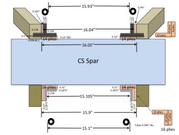
Engine Mount Extrusions

Finally, in prep for my upcoming reintegration back into the build, I performed the ceremonious refilling of the Flox and Micro containers.  And cleaned my respirator masks.  (Hey, if this isn’t a clear indication of getting on with the build, I don’t know what is . . . ha!)
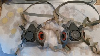

Cleaning respirators


Chapter 22 – Trio A/P Pitch Servo

Today I got my Trio Pro Pilot autopilot pitch servo back from Chuck at Trio Avionics.  As he said he was going to do he upgraded my pitch servo with the Auto Trim feature.  And in short order too!

Here’s the pitch servo before I sent it to Trio.  Note that there’s only 4 wires coming out of the servo.

Trio Autopilot Pitch Servo

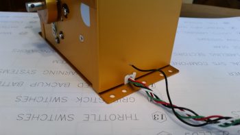
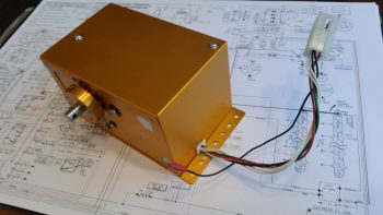
And here’s the pitch servo after the Auto Trim feature was added.  Note that there are now 6 wires coming out of the servo, the 2 extra obviously being for the Auto Trim feature.

Trio autopilot pitch servo

As an aside to this story, the US Postal Service gets a ding (pardon the pun) against their service in my book, considering that as overpacked as I had that servo in the box that Trio had sent out my autopilot control head to me, the Post Office still managed to crush the box and damage the bottom plate of the servo!  Luckily there was not such damage on the return trip.  Here’s the damaged bottom plate that Chuck threw in the box when he shipped the servo back to me:

damaged pitch servo plate

Still, no worries and all is good.  One more item off the list and I can move on to the actual build . . . SOON!  (I promise!)

My first Long-EZ ride!

Yes, it may sound a little crazy or unbelievable, but I have been building my Long-EZ for over 5 years now and have never actually flown in one until this past week!  The timing actually worked out in the grand scheme of things.  If tried a bit last year at Rough River to get a ride but never actually did.  When my buddy Marco bought his Terry Lamb-built Long-EZ a couple of months ago (a beautiful airplane), he had to A) learn to fly it, then B) fly off 10 hours before he could fly passengers in it, thus satisfying the insurance companies demands.  Last Sunday (7 Aug) he finished his 10 hours, and due to both our schedules, the only time I could fly with him in the near future was Monday, 8 August.  So I scooted down to Marco’s Sunday evening, we flew Monday, then I returned back to the DC area Tuesday.  I headed straight to the airport to pick up yet another out-of-town visitor!

I have to say that while flying the Long-EZ for the first time was a blast (albeit from the back seat), it was also a bit anti-climatic.  The tales and yarns of how difficult and unique this bird is to fly seem to be a bit over-dramatized and exaggerated, and I’m not sure why. This plane is a pleasure to fly and it handles very well.  Of course, the overarching impact of my personal historic first Long-EZ flight is that I am incredibly motivated to get my bird built and in the sky!

I hope you enjoy the video!  Cheers.

Chapter 22 – Trio A/P Servo Upgrade

Quick update in that today I sent the Trio Pro Pilot autopilot pitch servo to Trio Avionics to have the Auto Trim feature added to the servo.  As I posted before, I talked to Chuck and he will upgrade it for me shortly after they all get back from Oshkosh, so I wanted to time my shipment so that the servo arrives Trio right about the time he gets back from Oshkosh.

One more thing off the list!

The NOT Sexy Part of Building

. . . . Ah, but oh so necessary.

Today I finally finished logging all of my receipts & invoices into my Project Receipt & Invoice Binder.  Yes, true, it’s NOT building!  But this was one of those things I needed to get done for my peace of mind.  And, practically, so I wouldn’t re/order stuff I already had on hand.

With my moves literally all around the world starting within just a few months after I started this project (2011), and having had consistently sent parts orders to materiel pre-deployment sites (aka “friends’ houses”) in numerous locales around the US mid-Atlantic region while OCONUS, I needed to get the associated receipts and invoices FINALLY logged in my tracking spreadsheet and physically into one location.  So I repurposed this binder, and voila!  And after a few weeks of pecking away at it a few hours at a time . . . I’m DONE!

Receipt & Invoice Binder

I also had an extra Table of Contents page so I threw that in the front of the binder just to class it up a bit.

Receipt & Invoice Binder

Alright . . .  I have about 20 packets of hardware to stow away in the right bins and then I’m complete with all the electrical system stuff, this administrivia crap, and inventorying all the nit-noy hardware and getting it put away.

Thus, over the next few days I WILL BE starting on the shop to get that organized and back into build mode!

Chapter 22 – Why Vic?! . . . Why???

It’s funny to me how I can ponder on something for a fair amount of time and then as if by putting mental energy into a concept, it reveals itself in a some what short amount of time. As with many things lately, certain discussions have fostered various thoughts about various instruments, avionics and switches on my panel.  Yet another discussion I had with Marco about his recently purchased Long-EZ –which incidentally has proven to be quite the test bed in that the handful of discussions that we’ve had concerning his new bird have spawned a number of viable system designs mods in mine– and the comment that he made on wanting to have a Garmin-free bird (due to their high prices on data updates), got me to thinking a bit . . .  but admittedly, with everything that’s been going on lately, I really wasn’t thinking that much on it!

What I had been thinking about for some time was having a GPS with a decently larger screen size than the GTN650, but one that would still fit comfortably in my panel.  In fact, I was thinking about this even more after I learned that GRT had debuted (FINALLY!) the 8.4-inch HXr at this year’s SNF.

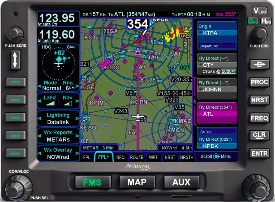
Well, not sure if you got a chance to read Vic Syracuse’s article on the Avidyne IFD540 GPS Navigator in the August 2016 edition of Kitplanes Magazine.  All I can say after doing a bit of research for the last 3 days on this puppy is WOW!  This guy is packed with a ton of features, and in addition, its screen size falls right in between the GTN650 and the GTN750, so it looks like it will really work well for my panel size.

Avidyne IFD540 GPS Navigator

Moreover, the Avidyne IFD540 is a drop in replacement for the Garmin GNS430, so the pinouts are nearly the same as it is with all Garmin GPSs.  I spent about a half hour confirming and updating all the component crosslink pins to ensure that this would work in my electrical system’s wiring schema, and it does!  I had to change the actual pin ID numbers on about 70% of the pins (the D-Sub connectors identifying numbers are different as well), but did the swap in my wiring diagrams in short order.

And yes, I did say last week that I was done with my electrical system planning for the time being, but apparently this is the nature of the beast in building a homebuilt experimental airplane.   So again, I think I’m done in having finished my electrical system planning (at least for now!).

Chapter 22 – A few Yays & an Oops!

Over the past few days I’ve pretty much finalized all I can with my electrical system planning at this time.  I would hazard a guess that over the past couple of months I’ve moved the “finish” dial on my electrical system design & documentation from the 89-93% range to the 96-97% complete range.  There are still a few more admin things I need to finish, and depending on any future changes in vendor-mandated installation requirements on my respective components, I’ve pretty much got the design dialed in to the point where I can implement the electrical system plan where permitted from here on out as I build.  I do have a couple of switchology decisions to make, but those won’t come until I mock up the panel and play around in a simulator-type setting while making airplane noises.

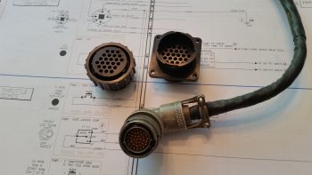
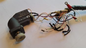
Moreover, I met another design milestone by creating wiring diagram 13 showing all the wiring for the 6 throttle handle-mounted switches.  Since I’m making the throttle handle removable I’ll be running all the wires through a 24-pin AMP CPC connector–the same style connector that I used on the nose gear actuator connectors where I swapped out the stock Molex connectors.  On the throttle handle I’ll be wiring all the switches with new wiring and swapping out the old stock circular Amphenol Mil-Spec connector with the much lighter and cheaper TE Connectivity AMP CPC connectors.

24-pin AMP CPC connector vs old

After removing all the existing electrical potting material and then stripping all the throttle handle switches of the myriad of resistors and capacitors, which created a near-impenetrable labyrinth around the back side of each switch, I was able to tone all the switches out.  I was pleasantly surprised to find that I had mistakenly ID’d the bottom toggle switch as a SPST switch rather than the DPDT switch that it actually is.  I had already targeted an $80 OTTO replacement switch for this position, but after this latest round of investigation I can belay that order and use the stock switch for my Landing Brake!

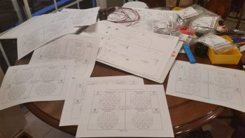
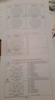
With my throttle switches clearly identified, and the wiring to & from each switch, I could then marry up my initial throttle switch diagram with the 24-pin AMP CPC connector and finalize the throttle handle’s P4 connector pinout diagram.  I have all my multi-pin circular connectors detailed in a PowerPoint slide deck (it just evolved that way).  And since I currently have seven connectors on the aircraft (P1-P7), I obviously need a diagram for each connector.  Unfortunately, I hadn’t created all the diagrams, so down another rabbit hole I went for a couple of hours to finish all the templates for all the circular connector pinout diagrams, as you can see in the pic below.

P1-P7 Connector Pinout Sheets

Now, each connector pair gets 2 pages detailing the pin assignments.  The first page (top of the 3 pages in the pic below) details the general information about each connector: number of pins, part numbers, mounting flange (if present), hole number schema, pins, sockets, and standard vs reverse sex connector.  The second/back page (middle & bottom in pic below, with bottom page info populated) shows the detailed pinout for each connector side, with wire colors and wire function/connectivity.  I of course finalized populating all this information for each side of the P4 throttle handle switches connector.

AMP CPC pinout diagrams

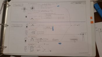
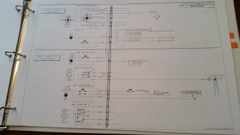
As for wiring diagram 13 depicting the wiring for all the 6 throttle handle-mounted switches, below top you can see the initial draft versus draft #3 in the second pic below.

Throttle Handle Switches

Throttle Handle Switch Wiring via P4

I knew that the top left throttle handle switch that was clearly designed for a specific F-15 system was not going to work for my application.  This switch is nearly heavier than all the other switches combined and in my estimation is probably a good 30% of the stock weight of the throttle handle as it was shipped to me.  I pulled this switch and then spent a fair amount of time identifying its replacement.

Removed F-15 throttle handle switch

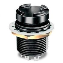
And here’s what I came up with: the OTTO T5 mini trim switch.  The more complete description is a commercial grade 4-way plus center pushbutton trim switch.  The pic below is a stock photo off the Mouser website.  In actuality, the switch I ordered does have the “stadium” grips on the top as this pic shows, but it differs in that my switch is gray and it is press fit vs. threaded mounting.  If you’re curious about the switch assignments, here they are:

  1. UP – Trio Autopilot Fuel Information Screen Cycle
  2. DOWN – AFP30 Air Fuel Data Computer Screen Cycle
  3. LEFT – GRT HXr EFIS Page Flip
  4. RIGHT – Garmin GTN650 NAV Source Select
  5. CENTER – Garmin GTN650 CDI Source Select

OTTO T5 Mini Trim Switch

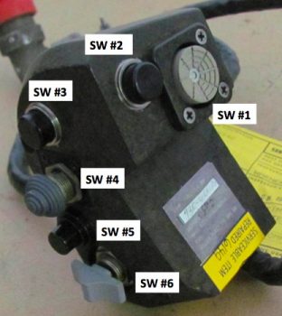
As for the other Throttle Handle Switches, here’s the layout:

#1 – Outboard Front – 5-Position Mini Switch (described above)
#2 – Inboard Front – COM PTT
#3 – Inboard Side Top – COM1 Freq Flip-Flop
#4 – Inboard Side 2nd Down – Nose Gear UP/DN
#5 – Inboard Side 3rd Down – A. Remote Start Arm   B. Trig TT22 XPDR Ident
#6 – Inboard Side Bottom – Landing Brake UP/DN

Throttle Handle Switches

Alright, moving on!

As I was reviewing the P-connectors pinout diagrams, I set about to confirm some info on my P3 (Trio autopilot pitch servo) & P7 (Trio autopilot roll servo) connectors.  For some reason our good friends building non-TSO’d products for our birds typically use auto grade Molex connectors.  Being a true disciple of Bob Nuckolls, and having had other discussions with some smart bubbas on this topic, I am simply (and clearly) not a fan of Molex connectors.  Especially for the autopilot roll servo which will be located on the back of the center section spar in the engine compartment.  I want more environmental protection for this connector.  So, my dear friends, I was confirming the wire colors and pinouts on the P7 connector with the Trio install manual–since I had just ordered a reverse sex 4-pin sealed connector (so that it was physically impossible to connect up either servo in the wrong spot) on my last Mouser order– AND that’s when a disturbing question popped up concerning both the P3 connector, and the pitch servo.

You see, I had incorrectly ordered a 4-pin connector for the pitch servo in my haste to get all the required electrical pieces parts in hand.  It didn’t require any O-ring seals since it was in the avionics bay, so I simply pulled the trigger.  But while reviewing the Trio autopilot installation manual wiring diagram, I realized I had forgotten about the 2 extra wires coming from the pitch servo for the Auto Trim feature.  But why had I forgotten these wires?  I then pulled the pitch servo out and –what?!– only 4 wires!  Hmmm, maybe they were tucked inside the servo since this was an “optional” (key word here folks) feature.  I pulled the cover off the servo, and no joy.  There was not an extra pair of wires or connection points inside this servo.  Ok, what’s going on here?

I went to Trio’s website, and I still got the impression that the Auto Trim feature was a standard feature of Trio’s Gold Standard servos and merely labeled as “optional” since the builder had to add a relay, bridge rectifier and wire it all up for it to work.

Trio Autopilot Pitch Servo

I called Chuck at Trio to ask him about this latest puzzling revelation.  He and the Trio gang were just getting ready to head out the door to Oshkosh, but he took the time to have a detailed conversation on the status of my pitch servo.  So here’s the deal: A few years ago the Auto Trim feature was an actual priced option for the Trio Gold Standard servo. However, they decided to simplify production and simply make the Auto Trim a standard feature on the pitch servo, yet still optional as to if the builder/owner wanted to utilize it or not.  Since this was my impression all along, it never entered my brain as a data point when I bought these servos from a fellow homebuilder (Rans S7 I believe) off of Ebay.  If you recall, I had the servos sent straight to Trio who made one engineering upgrade, ops checked the servos and then sent them on to me with the install kit required for a Long-EZ. All was good!  Or, so I thought.  Hmmm…

Trio Autopilot Pitch Servo

Okay, lesson learned!  The money I saved on buying these servos off of Ebay has been reduced to virtually nil now that I’ll be sending the pitch servo back to Chuck, along with a couple hundred bucks, to have the Auto Trim feature installed.  All in all, no big deal.  I’m just glad I caught it early on.  And I guess technically this was two Oops since I also had to spend $10 to include all the pieces to make up a 7-pin AMP CPC connector on my last Mouser order!  [Note: I’m using a 7-pin connector since they don’t make a 6-pin.]

In closing, I currently have everything either on hand or on order for my electrical system. As I did a couple of years ago, I’ve included a rundown below of all my electrical system diagrams (wire book) up to this point.  As you can see, I have a few more systems to figure out, but nearly all of the really critical stuff is complete.  As for the Main, Battery and E- Busses, I won’t diagram those out until all my other system designs are completed and installed.

0. Index Page
Z.  Z-13/8 Electrical System
A.  Switches, Circuit Breakers & LEDs
.99 Grounding Busses
1.  Panel Components
2.  Radio & audio system
3.  Panel Power
4.  Electrical System Components Location Diagram
5.  Aircraft Wire Labeling Sectors Diagram
6.  Nose Gear
7.  Pitch & Roll Trim Systems
8.  Lights: LDG, TAXI, NAV, STROBE
9.  Engine Info Management
10. Fuel System
11. Cockpit Lighting
12. Landing Brake
13. Throttle Handle Switches
14. Control Stick Switches
15. Integrated Backup Battery System & X-Bus
16. Alarm & Warning Systems
17. Charging System
18. AG6 Warning Annunciators
19. Electronic Ignition
20. P-Mag Ignition
21. Heater System
22. Starting System
23. ELT
24. Heated Pitot Tube
25. Trio Autopilot
27. Main Bus
28. Battery Bus
29. E-Bus
30. Long Wire Runs

This wraps it up currently for my electrical system design and planning.  From here I’m going into house cleaning mode (multiple out of town visitors arrived and/or arriving!) and shop cleaning & organization to move forward on the actual build…  woo-hoo!