Chapter 7 – Fuselage Glassing Prep

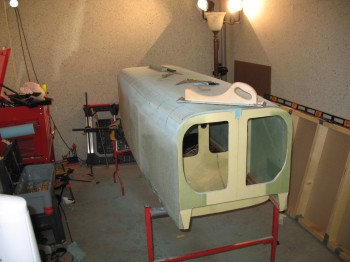
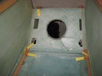
I finished sanding the fuselage near the Main Gear extrusion bolts, and the Firewall junction with the CS (Center Section) Spar both top & bottom.  I then sanded the top & bottom longerons to match the Firewall outline.

I checked that the fuselage was level and straight.  I also double-checked the firewall positioning and confirmed that it was level, straight and square.

My last action of the evening was finding and marking the fuselage centerline.

Chapter 7 – Planning the Way Ahead

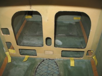
After a power nap I reviewed Chapter 7 of the plans on skinning the fuselage.  I took a hard look at the strake cutouts as well (the holes on the insides of the fuselage that allow access into the “wings” to store baggage, etc.).   I hauled the plans, A-pages and firewall out to my shop to mull over my next steps.  I mounted the firewall and in doing so, noticed a few more hairline cracks developing in the foam fuselage at the aft end of each side.  I need to get the fuselage glassed soon!  I checked the firewall: it fits well and is square.

One thing that is not fully captured on this site is the planning steps that go into each build action.  I have been talking to a number of highly experienced canard builders, and although they quite often don’t agree with each other on build methods or project mods, I take what they have to say with a lot of weight and consideration. I also understand that if I do anything outside of the guidelines of the plans, it will quite often be met with a fair amount of wailing and gnashing of teeth!  In light of this, one modification that I looked at and assessed in-depth tonight was imbedding the rudder Nylaflow tubing into the fuselage sides.  It looks quite doable.

What is the advantage of doing this?  My rudder cables will be taking a more direct route out to the rudders from the rudder/brake pedals.  They will travel in-line straight from the peddle down the side of the fuselage, make a shallow ‘S’ curve and run near the top longeron through the Center Section Spar (again, no fibers will be cut, just gently gapped about 3/16″ for Nylaflow clearance) and then turn out towards the rudders.  Another plus is that it cleans up the interior of the fuselage and allows me to work on the rudder cable conduits on the outside of the fuselage vs. the inside, in pretty much the same manner as how the conduit is run through each wing.

I spent about an hour and a half mocking up the tubing path and how it corresponded with the strake cutouts, using as gentle of curves as possible.

Chapter 7 – Shaping the Fuselage

I started off my Long-EZ build today by reviewing the early Canard Pusher Builder’s Hints and the Landing Brake plans for about 2 hours.

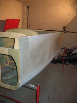
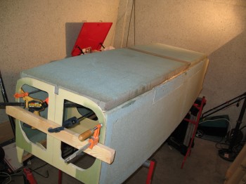
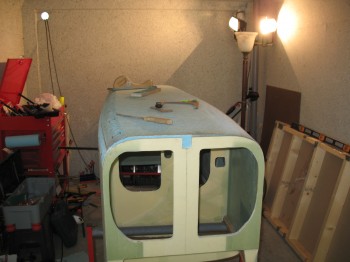
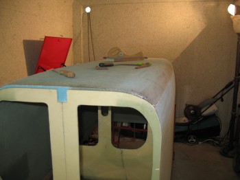
Then, because apparently it was Sanding Day (I hear Canardians are pushing for that to become a national holiday!), I sanded the bottom corners of the fuselage to shape.  The final result may have just a little bit less foam taken off at the corners than the plans show, but the lower corners follow very closely to the template and have a good flow.
Chap 7 - Shaping the fuselage

Chap 7 - Shaping the fuselage

Chap 7 - Shaping the fuselage

Shaping the top of the fuselage at the longerons, in time & effort, was comparatively EZ.
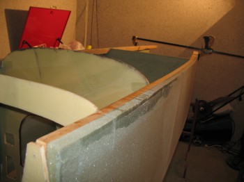
Chap 7 - Shaping the fuselage sides

Chap 7 - Shaping the upper fuselageTo be honest, I don’t really care for the shape of the top template… it seems a little too flat and could be just a bit more rounded.  But maybe that’s what some folks say in general about the shape of the Long-EZ fuselage!
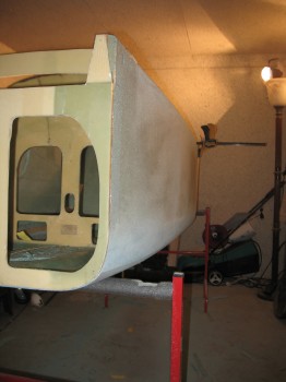
Chap 7 - Shaping the fuselage

Chap 7 - Shaping the upper longeron

I also weighed the fuselage today.  Mine weighs 46.6 lbs vs. Mike Melvill’s 41 lbs at this stage.  Considering the extra glass, micro and flox I added both on the sides & bottom during the repairs, and the fact my rear longerons are a just a tad bit thicker, I’ll take the 5.6 lbs heavier fuselage and press on!  Also, I haven’t given the fuselage tapes and repairs a thorough sanding yet, so that will take at least a little weight off.

And unrelated to the fuselage, once I finished shaping the fuselage I drug out all my raw 2024 aluminum pieces and marked up all the various pieces and parts that would come out of them.  It was kind of like putting a puzzle together, but I had fun trying to plan the use the entire length of aluminum while minimizing any significant leftover pieces.
Chapter 7 – The Beginning: Carve it up, Man!

Chapter 7 – Fuselage Exterior

I pulled the peel ply from yesterday’s layups.  Overall, everything looked great. I marked some punch list items and I’ll probably have to add another BID tape a place or two, but it all looks real solid.

Fuselage Punch List - Instr. Panel

Continue reading

Chapter 6 – Fuselage: Bottom Glassed to Sides/Bulkheads

After the bottom cured I noticed that there was a very thin gap between the fuselage bottom foam (at the very front edge) and the aft edge of F22 bulkhead.  This was caused by me centering the foam and compromising between getting the foam acceptably placed & centered on the bulkheads and sides, and getting the front edge of the fuselage bottom to make contact (or as close to contact) to F22 as best possible.  This small gap, about 1/32″ on the left side to almost an 1/8″ on right side, was in part caused by the nose being slightly askew, and the more extreme curvature (football shape) of my fuselage.

On a normal fuselage, F22 sits a lot more square (perpendicular) to the fuselage sides; whereas on my build, the foam sides needed to be beveled to an angle for F22 to sit (or mount) to them squarely.  In retrospect, mine weren’t beveled nearly enough to keep F22 mounted straight across the front.  Since the fuselage sides were beveled/angled (by virtue of them being pulled inwards so much), it created a very slight inward bow of F22 at its midpoint/centerline.

Chap 6 - Fuselage bottom attached to sidesI sanded a thin wedge of foam, and micro’d it to the fuselage bottom foam on one side and floxed it to the aft bottom face of F22.   I then clamped F22 tight against the foam wedge insert and the fuselage bottom’s front edge.  I also added some flox into some very minor gaps between F22 and the bottom triangular longerons. Continue reading

Fuselage Bottom Glassed – Chapter 6 Closeout!!

I removed the peel ply from the fuselage bottom final layups.  Since I laid up the front just a tad more wet than I normally would (just a bit!), I sanded it heavily to remove any excess epoxy & rough spots, and smooth out any of the glass transition edges.

Chapter 6 - Fuselage Nose Gear Well

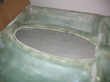
I cut around the edge of the nose wheel well outline with the Dremel tool, exposing the duct tape underneath after I pulled off the glass piece.  BTW, this isn’t per plans.  The plans say to cut out the wheel well area first, then lay up the fuselage bottom glass to the edge of the cutout.  I thought it seemed easier to do what’s done in Chapter 7 with the landing brake, by just laying down a layer of duct tape.  Once I did that, then I didn’t have to concern myself with another edge,  I simply just glassed the area as a normal layup. Continue reading

Almost done glassing fuselage bottom…promise!!

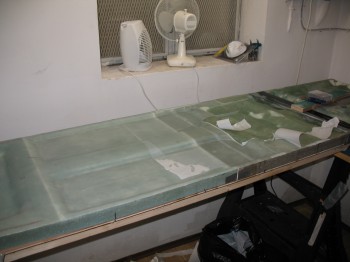
I removed the peel ply from last night’s layups.  If you’ve never seen fiberglass after peel ply is removed, it can often leave some ridges and strings along the edges of the laid up peel ply.  That is why I usually try to use as large of a single piece as possible for whatever I’m peel-plying to eliminate all the strings and funky edges.  Thus, I took about an hour to clean up all the peel ply “gifts” leftover from the layups.

Chap 6 - Glassing fuselage bottomAfter all the peel ply crud was cleaned up, I used 4 scrap pieces for the final 1-ply BID layup to the front 4 compartments of the fuselage bottom. Continue reading

Chapter 6 – Glassing Fuselage Bottom

Unfortunately I don’t have any pictures on this post.  (READ: For historical purposes and might make for some dry reading!)

I micro’d and then glassed the front right-hand corner ding (it was a little crunched from the move) and 2 side delaminations that measured around 1/2″ x 2-1/2″.

I glassed 2 separate pieces of 1-ply BID as a second layer between the FRONT of the rear (GIB) seat and the front (pilot) seat, overlapping by about 4″ onto the raised center part of the floor (i.e. middle of fuselage floor).  I then glassed 1-ply BID from the rear seat trough to the front edge of the front seat, which constituted the second ply in a 2-ply BID layup.  The first ply being the first layup above made up of 2 pieces, then covered by the second ply, made up of one piece and overlapping the edges of the first ply just a bit.

Finally, I used 2 pieces of BID overlapped by about 1-1/2″ at a 45° angle to the side of the fuselage bottom.  This  45° seam cut right through where the front seat back would touch the fuselage bottom.

I then peel plied all the layups.


Chapter 6 – Fuselage Bottom Glassing & Repair

I cut the first ply (1 whole piece) of BID for the GIB (“Guy or Gal In Back”… the rear passenger, but the slang is “GIB,” so ya better get used to the idear, see!?) floor just forward of the rear seat ‘pan’ I glassed last night. I also cut the second ply (2 pieces) that would be used later for the entire back half of the fuselage floor. And since I was cutting glass, I cut 3 more separate pieces for more delam repair layups on the front half floor.

Glassing Rear PAX's FloorI glassed the first layer of BID on the GIB floor area as well as laying up glass for the remaining delams: the rear incline of the front seat divot, and two spots at the very forward edge of the fuselage floor. Continue reading

Chapter 6 – Back to Square One!

The journey of a thousand miles begins with one step . . .

AND:

How do you eat an elephant?  One bite at a time!  Right?!

So you can call me chicken but I’m not taking any (more) chances with this fuselage bottom!  I’m going to glass it step-by-step, and make sure I concentrate on each area. With these deep funky crevices that I have to glass down into, I want to ensure I can fully focus on smaller sections of glass.  [I double checked my measurements for all my fuselage bottom divots against the plans, and they were all pretty darn close… In case you were wondering!]

Since I now have my fuselage “HOLE” repaired on the outside of the fuselage bottom, I’m ready to glass.  The bottom fuselage foam is 1-3/4″ thick and I have to make it curve sharply downwards at around 8″ from the back edge, thus curving it sharply upwards from that 8″ point to the back edge.  I don’t really like doing this because it has the potential to jack up the glass immediately under the clamps, but my plan is that I’m going to layup the glass and then clamp the edges at the apex of the curve to drive this fuselage down into the sled and have it cure with the nice curve it needs to follow the bottom contour of the fuselage.

Chapter 6 - Glassing rear seat area Continue reading