Chapter 26 – Seat Headrests

I noticed an email this afternoon from Alice at Oregon Aero seats. She is working on my seat cores and asked me for the dimensions of the headrest pads.

I was under the assumption that those were going to come later, and honestly was up in the air over what I was going to do about my front seat headrest. Nonetheless, I took a good half hour break from tearing down the temp walls in the workshop to gin up some PowerPoint pics to convey my desired headrest pad dimensions to the Oregon Aero folks.

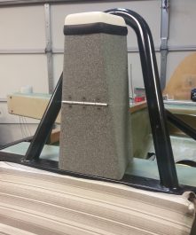
Since my front seat headrest is also a small lockable storage compartment [Hey, take as much & as many as you can get on these airplanes!] that hinges forward, I wasn’t sure if I should have a headrest pad just on the top portion of the headrest? Or perhaps split the pad at the hinge and make the top segment removable while the bottom stayed in place?

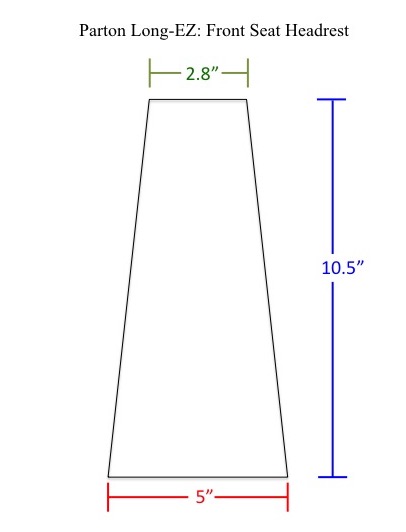
Regardless, I wasn’t going to run them through the mill on my mental shenanigans, so I simply provided the dimensions for the entire face of the front headrest. We can dial in the fine print details later and this will give use a good baseline jumping off point.

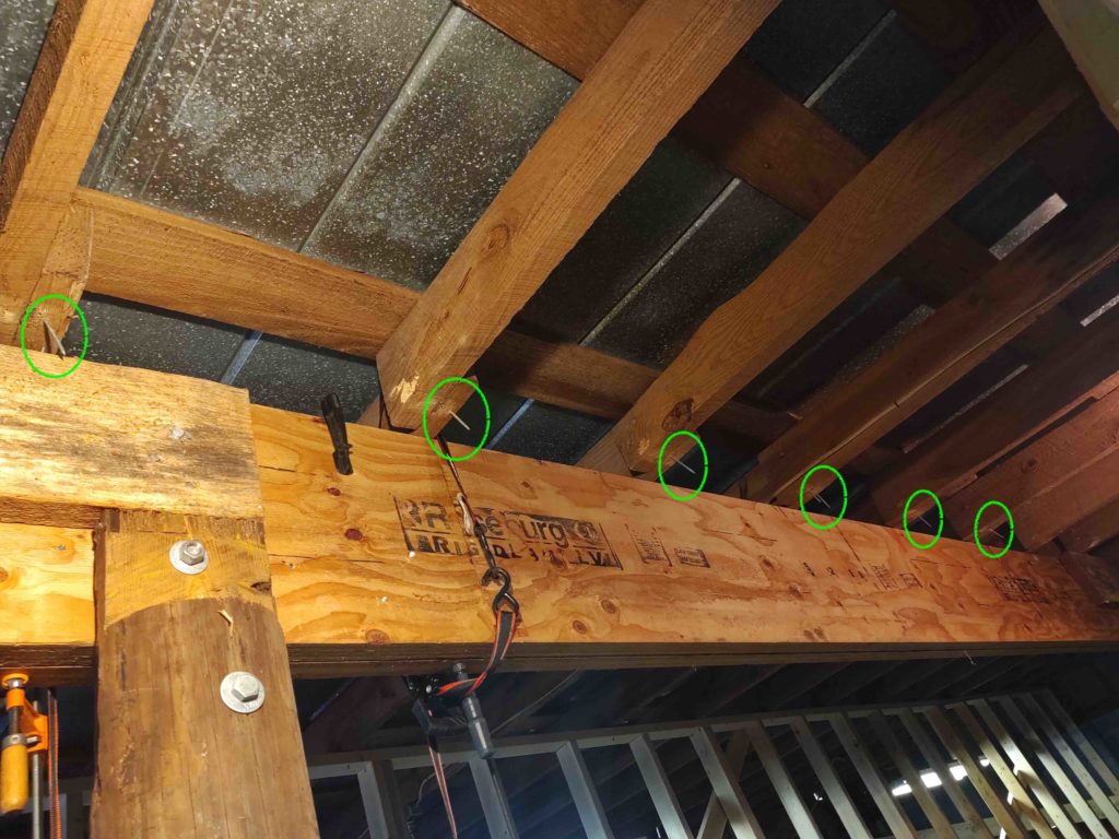
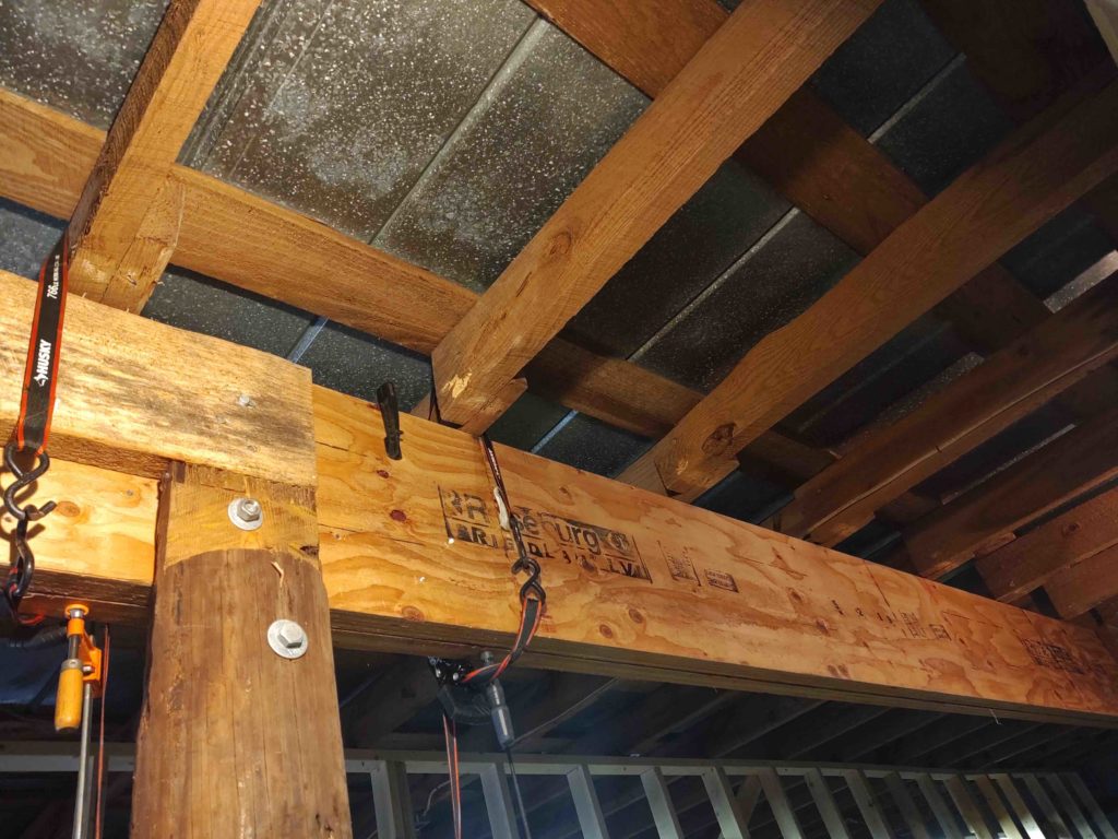
For the rear seat headrest I wanted a nice sized pad for the GIB, but I don’t want to have to remove the headrest pad to get access to the 4 CAMLOCs that hold the headrest front cover plate over all the electro-whizzie goodies inside the headrest compartment. I stole this simple access idea from Wayne Blackler as I noted his rear seat headrest housing hardware was accessible without removing the headrest pad.

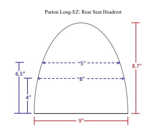
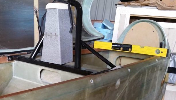
Thus, comparing the shape above might seem a bit narrower than one would think would cover the entire rear seat headrest plate because as I explained above, it simply doesn’t. Pardon the level in front of the rear seat headrest plate, but believe me when I note that there’s a CAMLOC in each lower respective corner, of which the above headrest pad will be attached with its outer edges just inside of to again keep all the CAMLOCs uncovered.

Maybe a bit TMI for simple headrests, but remember, half the battle for me in building this thing is documenting what the heck I did so I can go back and remind myself why, when and how I did what!

Tooling Up – Temp Walls Down

With the beams up and secured and the middle pole removed, today is temp wall removal day!

I started by removing the aft right wall section and the front left wall section, as the shot below shows…

And from the opposite direction:

Quite a few hours later, I had gotten all the walls down and disassembled. I stacked up the nails free lumber against the side wall, while the wood laden with nails I piled up for later… “later” as when my old elbow feels able to pound nails out for a solid hour!

Here we have the last section of temp wall left to be dismembered.

Again, from a different angle showing the free standing middle beams.

And with the bird put away for the evening. I did not set the fuselage in “its place” yet because tomorrow I’ll finish removing the remains of the old center pole and filling the hole with concrete.

It’s supposed to be quite stormy this weekend… lots of wind and rain, so no building the air compressor bump out for a few days. I have a ton of other indoor tasks to undertake so I’ll continue to stay busy on the workshop prep.

Tooling Up – Beams Complete!

I started off today by cutting and installing the right side 2×10 internal support strut by nailing it to the existing pole. Shortly after these shots were taken I ran to Lowe’s for some more hardware and installed 2 x 5/8″ lag bolts to hold this puppy into place.

Again, this added support strut is just a bit of insurance to have a physical support under and across the new beams and attached to the old post. These beams are quite heavy and I figured it could do nothing but help the old posts to have an extra helping hand support-wise.

I then spent well over an hour marking, augering and installing pairs of 1/2″ x 10″ lag bolts at the top and bottom of each internal support block position… 8 pairs total. They are bit difficult to see on the front side of the beams, but they’re there.

Here’s an aft side shot of the pairs of lag bolts all down the aft face of the beams.

I then finished wrecking my right elbow by nailing in 12 joist-to-beam hurricane tie brackets.

I missed 2 joists because the top 1/2″ lag bolts happened to come through at those spots, so I’ll buy 2 opposite style ties and install them on the opposite side of the joist as compared to these already installed.

I then cut and installed the left end 2×10 added support strut. I do need to do a bit more work to dial in the attaching lag bolts, but it’s pretty darn close to complete.

Yeah, a couple minor things to polish up, but I’m calling the beams install complete!

Tomorrow I’ll tear down the front and aft temp walls, as well as finish clearing out the remaining old wood from the now-removed middle pole to fill the hole with concrete.

It was a challenging project, but the space afforded and ability to have the Long-EZ project in this area with wings attached is HUGE!

Tooling Up – Beams Installed!

Before I actually got to bolting the new consolidated beams into place I treated the bottom foot of some 2×10 interior support posts that I will add to the inside of each existing telephone pole-style post… for a sort of added insurance policy to ensure these massive beams have enough support. This shop is quite old, and although the end posts appear to be very stout, I just want another layer of support just in case.

Since the bottom of these support boards will be resting upon the concrete floor, any power washing or water action on the floor will eventually see the bottom of these boards sucking up water and then rotting away. So yesterday I coated the bottom with some outdoor roof-sealing caulk. Today I’ll use the same water sealer as I did on the roof, and then cover that with some white water-resistant primer.

Here is the right hand interior added post support board ready to be cut to length and installed.

While the sealing paint was drying, I then got to work on finishing up drilling the aft bolt strap that connects the top set of beam bolts to the bottom set of post bolts.

After I drilled the strap and installed the bolts on the right side I primed the post with a couple of coats to ensure it would dry before the interior added post support board was installed.

You may wonder why I painted the entire post? Well, the tar, pitch or whatever coating they put on these poles to preserve them is quite overpowering. It’s not as bad now in cooler weather with the shop opened up and a breeze going through, but believe me, the smell is quite overpowering and it has to be dealt with as best possible.

Eventually, as I get to each post, they’ll all get covered in primer and painted to help seal in that awful smell!

Here is the left side (looking into the shop from front) beam secured to the post via 5/8″ lag bolts.

This makes the beams officially installed! Of course I still have to drill and install the 8 pairs of 1/2″ lag bolts in the interior of the beam at each internal support block point. I also need to nail in hurricane straps on the aft side between the new beams and ceiling/roof joists.

At that point I’ll be officially finished with the beam install and can start dismantling the front and aft temp walls.

Tooling Up – Shop Beam

DAY 7:

Today I got the internal support blocks nailed into place on the right side (in the pics below) of the beams, just below the existing beam that will be sandwiched between the sets of new beams.

I then prepped the first of the aft side new big beams that will go up.

And then hoisted ‘er up into place.

Once the first aft side beam was in place I set it and nailed it to secure it into position.

I then prepped the second of the aft side beams –and the last of all the beams– to go up.

And hoisted the last beam into place.

I then did the same as with the first aft side beam: set it into position and secured it with a massive number of nails.

I then hung the aft side metal straps that adjoins the top pair of beam bolts to the lower pair of post bolts. I will need to drill out the middle two bolt holes as I did on the front side, but this gave me an idea of what I need to do tomorrow.

I also realized that my 5/8″ x 10″ long top bolts are barely too short and I will need to go with 12″ long bolts to show some thread after the nut is secured.

I’m very pleased that all the beams are in place, but I still have a fair amount of work to do before this project is finished. Tomorrow I’ll do a final set of the main beam and post bolts, along with the associated straps.

And if able I’ll drill all the interior pairs of holes at the support blocks and mount the 1/2″ lag bolts.

Chapter 17 – Pitch Trim Spring

After 5+ years of looking, I found ’em! Thanks Mike!

One system in the Long-EZ that is not well-covered out there in the building community ether is the pitch trim system. That is, if you’re not going with the original stock springs and mechanical lever.

For electrical pitch trim the overarching style in use on the Long-EZ seems to be the Davenport style, where a composite paddle is secured to the elevator torque tube and then connected to typically the same size actuator as used for the Landing Brake. Reportedly this works fine and I had planned on going in that direction, but fairly quickly realized that with the shear amount of stuff I had packed into the panel –not to mention my odd-duck Triparagon– that the Davenport style was not going to work for me.

My seemingly-elusive search culminated in my choosing an Electric Pitch Trim system that was designed by Cozy IV builder Vance Atkinson. Most canardians know Vance since he makes & sells the spiffy fuel site gauges. Well, after a discussion in January 2014 regarding his pitch trim system, I decided to use his design in my Long-EZ.

One issue I spoke with Vance about was where to secure the springs he identified on his system overview page. He called out an Ace/True Value Hardware spring #196 that had dimensions of 6.25″ long x 5/16″ diameter. Well, as hard as I and Marco looked for these darn things, we never found them. Even contacting the Ace main office to see if they carried them anymore, to which they replied that they were not in their system any longer.

A few months ago Mike Beasley contacted me to discuss his pitch trim system. He had noted that I was not using my Davenport Leaf Spring + Firgelli Actuator system and wanted to buy it from me. I sent it off to him and wished him luck.

Well, unknown to me until Rough River, Mike had gone down virtually the same decision matrix I had with his own final realization that the Davenport style took up a bit too much real estate and wasn’t going to work for him neither. In fact, Mike, Marco and I had a fairly in-depth brain-storming session on the Atkinson pitch trim system, the result of which was Mike leaning strongly toward it.

Ok, so today I get a text from Mike that he found the ever elusive #196 springs at his local Ace Hardware store! I was flabbergasted since I had looked in at least 15 stores over the past few years, just in case they still had some by any off chance.

Curiosity got the best of me and I went to two local Ace Hardware stores, and wouldn’t you know it –in somewhat of irony– the store a mile from the airport had a bunch of them! I grabbed 4 of them to ensure I had extras, and will probably grab a few more.

Amazing, but here is photographic proof! ha!

Crazy adventure this airplane building. Strange how things work out and how patience truly does pay off sometimes!

One big side note: During the first half of 2014, while Marco was machining my Atkinson pitch trim spring housing, I bought close to $200 worth of springs looking for a 6.25″ x 5/16″ diameter spring. As grateful as I am to Vance for sharing his electric pitch trim system design, after actually getting these #196 springs in hand, I realized he had inadvertently/mistakenly sent me on a wild goose chase. Yes, these springs are 6.25″ long, but they ARE NOT 5/16″ in diameter, ID nor OD. These fit inside the 0.75″ tube and are close to 5/8″ diameter. Might have been a typo on Vance’s diagram, but it definitely made my life an adventure for quite some time trying out springs –based on those specs– that were simply to small to work in the spring tube.

Tooling Up – More beam stuff

DAY 5: As I mentioned previously, I wasn’t going to get much done this weekend on getting the big beams installed in the workshop, but in-between my running about I did want to get some smaller but significant tasks knocked off the list.

I had a real heck of a time pulling the final existing beam down from the ceiling. There were large toe-nails on the top of the joists each side and I had to get up there and manually remove all those… quite a chore to say the least.

However, once the toe-nails on each side were removed the beam still would not come down easily. Something was still holding it up there tightly in place. Well, the something were toe-nails on the hidden side of the front joists (right joists in pic below) that were then covered up during the build by the aft-side joists (left in pic below). So after using my largest crowbar, the most brute strength I could muster and the requisite swear words, I finally brought the beam down… not without drama of course.

I had looped tie-down straps to catch the beam, which they did. But then subsequent maneuvering to get the beam down saw it slip out of one of the straps as it plummeted quite ungracefully to the ground below. Unfortunately, I had pre-deployed a sawhorse to set it on and it ended up crushing one of my nice adjustable (albeit plastic) sawhorses that I’ve had since the very early 2000s. Bummer.

Then came the remaining nails… Seems like every step of this middle pole removal / new big beam project has a curve ball thrown in!

I grabbed my trusty cutoff tool . . .

. . . And a good amount of sparks later had all the previously hidden toe nails lopped off.

This was the end of my solo 30-min Day 5 task.

Nails removed? Check!

Day 6 was a bit more entailed, since it involved some measuring and determining where my internal, intra-beam support blocks would go… right in-between the 2 sets of large beams. At these points I’ll drill and install two large lag bolts to secure the pairs of beams together for a nice strong cross support.

During this process I also clamped and nailed the front two beams to each other in essence creating one large beam. I then attached the internal cross-support blocks for the upcoming large lag bolts, on 3 ft centers.

Again, this was only about a 45 min effort in-between my weekend social duties, but it was a good step to get out of the way.

My final task before installing the aft set of large beams is to cut smaller versions of these internal blocks to place under the open section of the pre-existing beam (far right in the pic above, protrudes through the wall and supports outside eve joist). These blocks will also continue on 3 ft centers.

Then the aft side big beams can go up. I will have to do some drilling on the middle areas of the metal straps for the post lag bolts to go through, but that will be the final major task of getting these big beams in place to allow the temp walls to be dismantled and for me to enjoy my shop sans middle post!

Tooling Up – Shop Center Beam

DAY 3: I started off Day 3 focused on prepping the front side of the 3 posts to enable me to mount the front side two new large beams without removing any of the old beams. In fact, the middle post to be removed would stay in place until well after the new front two beams were in place.

Below the RHS post #3 with it marked and then cut to expose the original large nails used to attach the beam coming in from the right side (which will remain) to the post.

As you can see in the pics below of the 3 posts (L, Middle, R) I removed all the existing nails and hardware after cutting the wood post tops to accept the new 16″ beams.

Here we have all 3 posts cut and prepped for accepting front side beam #1, with the beam in the starting position below.

And here we have front side beam #1 up and in place atop the 3 beams.

Although in pics it may not seem like much work was done, but today was actually quite a long day. I then buttoned everything up for the night . . . including putting the fuselage back in place with it’s nose situated in its mini “garage” slot:

DAY 4 started off with prepping, then installing front side beam #2.

I then spent a considerable amount of time determining bolt spacing… then drilling the beams, posts and adjoining straps for the 5/8″ beam securing lag bolts.

I then notched the tops of the aft posts in prep for installing the two new aft large beams. Here’s the back side of RH beam #3.

And here’s the aft side of LH beam #1. Note that in the first pic there is an added roughly 2×4 sized piece attached to the original beam. I removed this piece of wood as I worked the prep of the aft LH side post area.

I not only removed the last of the original cross beams that I needed to install the aft side large beams, but note in the pic below that I have removed the middle post #2… which was the overarching goal in this entire endeavor!

This weekend will be light workdays due to an out of town visiting friend and some social commitments, but I do plan on hitting it hot ‘n heavy again Monday.

Tooling Up – Center Shop Beam

DAY 1: With the concrete pad for the air compressor curing it was time to start working on one of the last major shop upgrades I have planned: the removal of the left center post that will allow me to place the Long-EZ fuselage in the center of the left 2/3rds of the shop with the wings mounted.

The wingspan of a Long-EZ is about 26.5 feet with just an inch or two of clearance on each end. Well, from the left side wall to the outside of the right beam is close to 27 feet. With the wings mounted and aft of the outer posts shown in the pic below, there is just enough room to keep the plane in the left 2/3rds of the shop. Angle it a bit or cheat right a foot or two and I’ll have room to walk around each the end of each wing.

Of course to do this means that pesky center post has to come out. In turn, new beams must be installed. I had an engineer ascertain the structural requirements for my proposed idea. The solution turned out to be 4 massive 16″ high x 1-3/4″ thick x 27′ 6″ long LVL engineered wood beams to support the roof with the center post removed.

You can see these monsters on the shop floor in the pic above. Each beam weights over 200 lbs by itself.

Even though I have a fairly elaborate plan to install the front set of beams without having to remove the existing beams until the aft set of beams get installed, for increased insurance against calamity and for simple safety I will install temp support walls both behind and in front of the row of beams to support the wood roof joists.

Below is the first 12′ section of the aft temp wall.

And here it is installed. Now, due to irregularities in the shop floor and joists heights there is a slight curve in the wall to get a tight fit… even with shims. I made a wrong assumption when I measured the height of the joists in the middle and then cut all my studs the same length!

Here we have a series of shots showing the aft temp wall going up and its completion.

I then put the bird back in the shop and buttoned it all up for the end of Day 1.
[The fuselage looks huge here since it’s so close to the camera.  The spar is about 9.5′ wide and the temp wall behind it is nearly 28′ wide!]

DAY 2:

I started off today by removing the forms from the air compressor concrete pad. It’s not a perfect concrete job, but it will definitely do what I need it to do with the edges square, top level and concrete fill nice and compacted.

I had to go get another load of wood and shortly after I got back we had a torrential downpour for a good couple of hours.

I don’t have any pics of the build sequence, but here is the front temp wall completed up to the edge of the side of the fuselage.

I have a planned 29″ gap between the studs on this end of the wall that will allow me to nose in the fuselage inside the workshop at the end of each workday.

Tomorrow I should get the front temp wall completed and then start in on actually installing the front pair of new beams and removing the center post.

Chapter 22 – Transponder install

I’ve been thinking about my Trig TT22 Transponder install for literally years now.

Then, when Marco installed the same model to meet the 2020 ADS-B requirement it spawned even more discussion and thought.

My original plan was to mount the unit behind the panel and place the antenna out at the end of the right strake. Well, I forgot to account for the size & length of the serial adapter that lets the HXr control the Trig TT22.

Then came the ensuing interference between the fully assembled Trig TT22 transponder with serial adapter installed and the rather boxy TruTrak ADI housing. Moreover, I didn’t take into account the protrusion forward of the 90° TNC antenna connector… that takes up a fair bit of space on its own. The reality was –as originally planned– that installing the Trig adjacent to the TT ADI was going to be extremely tight, if even physically possible, without some significant configuration changes.

Another issue, even more critical than above, was after digging into the Trig TT22 manual I realized that my antenna cable run from behind the panel, along the front edge of the strake, to the transponder antenna on the outboard end of the right strake was going to be VERY close to the max length of what was acceptable according to Trig. And since my strakes are NOT installed, my estimate was best guess… at best!

Meanwhile, south of me . . . part of Marco’s menagerie of upgrades on the Long-EZ he bought was swapping out the old Nav/strobe lights with new LED lights. When he did this he was able to remove the old clunky Nav/strobe control box at the outboard end of the right strake.

Since the TT22 can be placed anywhere, he mounted the transponder control unit in the right strake where the old Nav/strobe control box had been. This configuration then allowed him to mount the antenna just forward of the control box about 15-18″ away with a very short antenna cable run.

I was down helping Marco do some of the initial wire and control unit placement and discussed the install with him after all was up and running. I was thinking seriously about doing the same Trig TT22 install but then one interesting point Marco made is that with the unit weighing in at 14 oz, he showed a notable aft-CG hit on his weight and balance. [NOTE: Marco has 2 each PC680 batteries in his nose while I only have one, thus his W&B finding is a bit more significant to me in my configuration]. Hmmm….

I then tabled the Trig transponder idea and focused on more pressing matters: my house sale in Virginia, the final move and then the subsequent house purchase in NC.

However, at this year’s Rough River I spoke with Chris Cleaver and a couple other Long-EZ owners who had put there transponder antenna in the nose area and had no obvious issues. I pondered that a bit but then left it alone again to address later.

Well, last night I had a bit of an epiphany regarding the mounting location of my Trig TT22 transponder. More specifically, I should note: the antenna. I decided that I will work the solution hard to mount the control head where I originally planned to mount it on the top shelf of my avionics mount: the Triparagon. 

Then the antenna will slip down between the front upright arms of my NG30 where there is a pocket there that really is empty space.  As a point of note, if I need to add any ballast it would go in this spot.

So this morning I grabbed the antenna and tested the fit inside this forward NG30 pocket.  Yep, it fit!  This install will result in way easier wiring of the control head, a short antenna run and fairly easy install (fingers crossed) of the antenna.

With my new Trig TT22 transponder install solution in hand, I then set about to update my wiring diagram. The updating of the Trig wiring diagram then resulted in two other diagrams needing updated. I also had not printed a few diagrams and desperately needed to print an updated table of contents page. Although my printer needs some new ink cartridges, I pressed forward (including about 45 min to get the printer on the new network) to print out these updated/missing wiring diagrams.

Bottom line: this should end the “where-to-install-the-transponder-and-antenna” saga.