Chapter 24 – Final hell hole glass

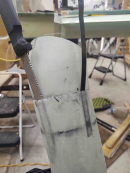
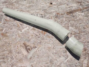
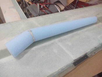
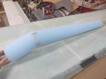
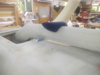
I started off today with an “unscheduled” task of slowly cutting away the aft edge of the hell hole hatch cover center channel to allow the flange of the aft RAM air scoop section to peak through.

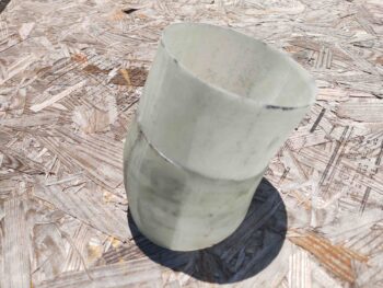
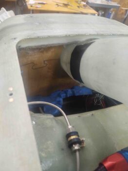
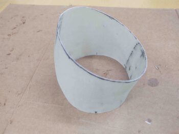
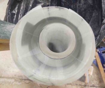
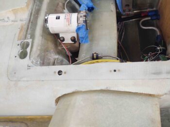
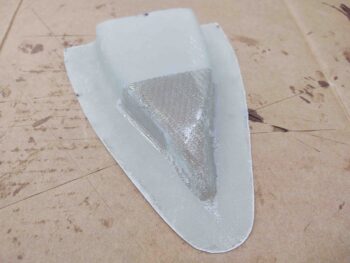
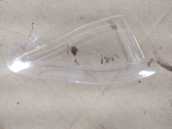
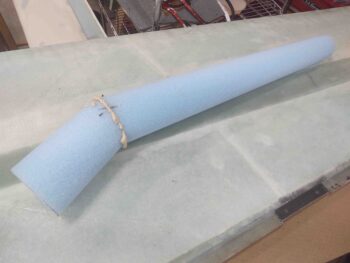
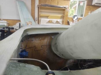
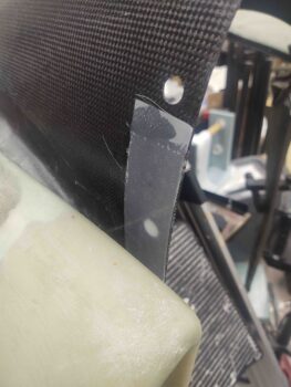
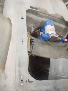
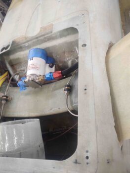
I included this shot simply to show the flange of the aft RAM air scoop piece inside the hell hole.

And one more pic from the aft side, fairly level with the bottom of the fuselage to show how much of the flange of the RAM air scoop piece peaks above (technically below) the surface of the hell hole/fuselage surface.

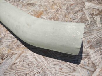
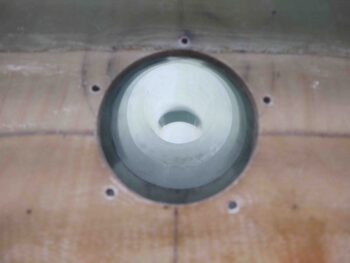
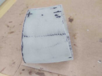
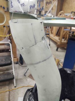
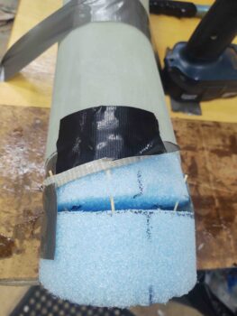
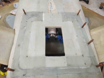
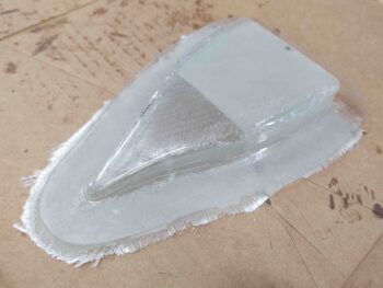
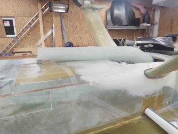
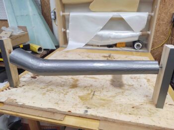
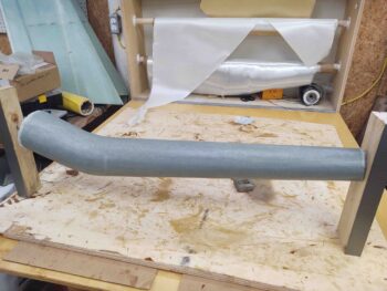
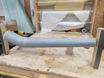
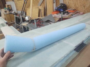
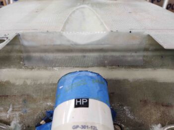
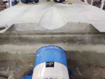
I then focused on getting the scooped divot on the bottom of the fuselage that provides clearance for the top side of the RAM air scoop as it transition aft into the hell hole.

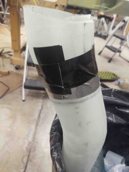
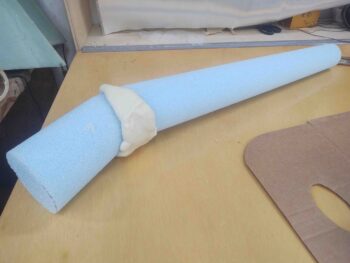
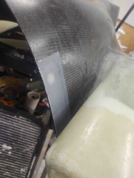
I taped up the top (bottom as situated) of the RAM air scoop where it interfaces with the scooped divot and then applied a small bit of pour foam in the divot.  The addition of the pour foam is to back fill some of the foam I took out as I was cutting away the bottom aft fuselage to create the space required for the RAM air scoop to be positioned correctly. Since I was estimating the amount to be removed I went a little too deep, so here I’m filling the surface back in to the surface of the RAM air scoop.

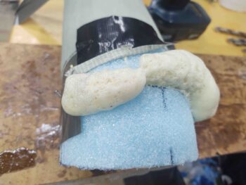
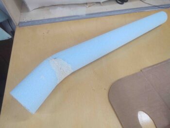
Here’s the fuselage-located scooped divot with the pour foam added, after I removed the taped RAM air scoop.

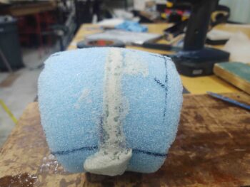
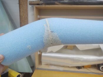
I then removed the excess foam, carefully sanded the surface and then created small “trenches” around the edges for flox corners.

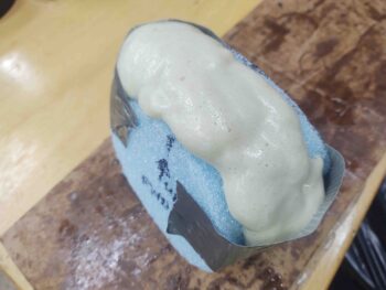
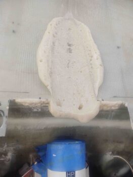
I then created the flox edges, micro’d the foam and laid up a ply of BID inside the scooped divot.  I then peel plied the layup.

After re-taping the top of the RAM air scoop I then remounted it and added a little weight to ensure it compressed the layup as best possible.

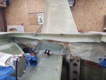
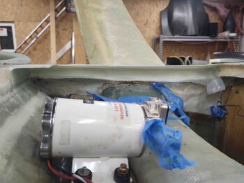
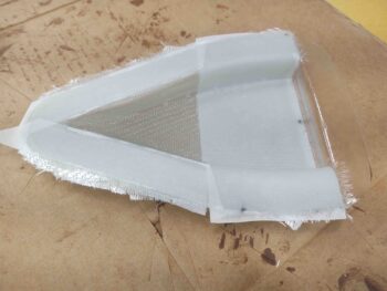
As the scooped divot layup cured, I trimmed, sanded and cleaned up the layups from last night: the aft hell hole flange and the aft RAM air scoop piece attach to the front face of the firewall.

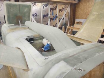
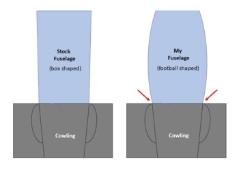
Also while the scooped divot layup cured I knocked out a task that’s been on my to-do list for quite a while now: the partial filling of the sidewall depression at the junction of the aft fuselage/firewall with the bottom cowling.  Again, this is a mitigation —not elimination— of the consequence of having a rounded fuselage matching up to a cowling designed for a traditional-shaped fuselage.

In my quest to mitigate this depression, I glassed a 3-ply stepped layup onto each side of these junctions: the aft fuselage/firewall edges.

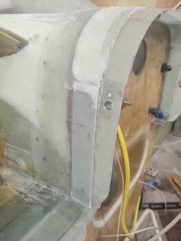
And the forward vertical sidewall of the bottom cowling.

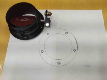
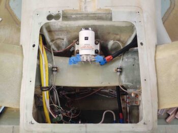
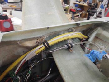
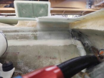
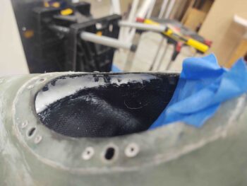
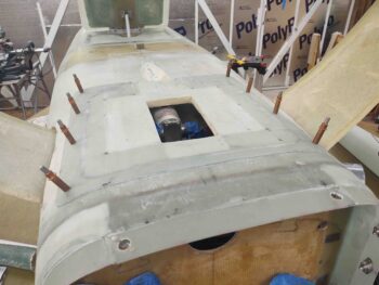
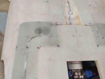
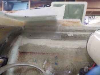
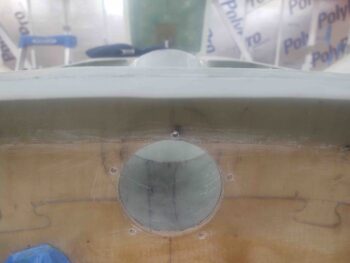
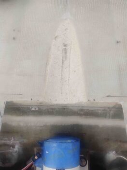
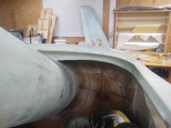
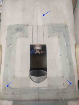
After the scooped divot layup cured, I pulled the peel ply, razor trimmed the glass and sanded the edges (top blue arrow).  Also note the initial cut lines I marked on the face of the hell hole hatch cover to remove this area in prep for the integration of the RAM air scoop into the cover.

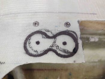
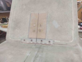
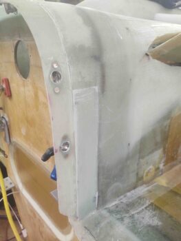
I then installed a K1000-3 nutplate in each aft corner of the hell hole flange.

Again, for these corner nutplates I had to use pop rivets to secure them since I couldn’t get the rivet squeezer up into those corners [Note the bare foam just to each aft side of the scooped divot… this will get glassed below].

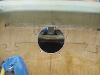
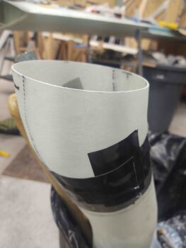
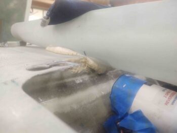
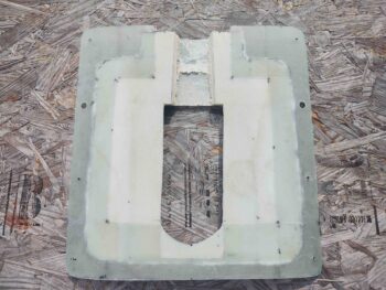
I then cut and trimmed the glass and foam of the marked center channel on the forward side of the hell hole hatch cover in prep for the integration of the RAM air scoop into this cover. I’ll note that I intentionally left the inside glass intact to keep as much structural rigidity in the cover for as long as possible.

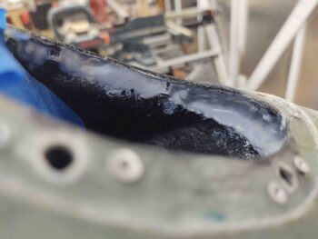
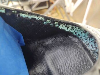
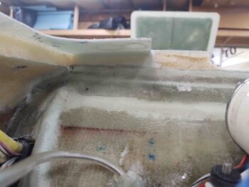
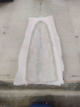
I then prepped the forward hell hole wall to finish glassing the only bare foam remaining in the hell hole.  Again on the top edges and around the scooped divot I created small flox corners.  I then micro’d the bare foam and laid up a ply of BID and peel plied it (pic #1).

A number of hours later I pulled the peel ply, razor trimmed the glass and sanded the edges (pic #2).

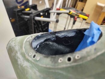
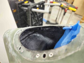
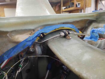
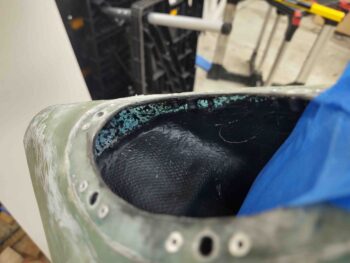
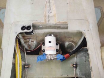
After the layup above —and after spending a good bit of time cleaning up some flox in the corners that had squeezed through from the outside perimeter layup— I added a drier micro fillet and laid up a ply of glass inside the aft RAM air scoop section where the scoop glass structure intersects the front face of the firewall.  I then peel plied the layup (pic #1).

Again, many hours later I pulled the peel ply, razor trimmed the glass and sanded the edges.

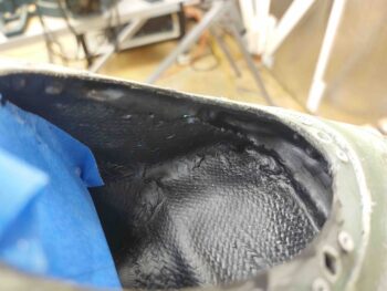
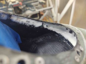
As you can obviously see, putting slimy BID over drier micro inside the “bottom” of a “coffee can” in an angled hard-to-reach area, resulted in some irregularities in the micro fillet.  No worries, in that I will simply go back over (yet another “iterative process”) it with another round of micro to create a much more uniform fillet inside the back wall of this RAM air scoop.

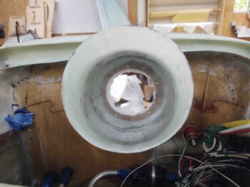
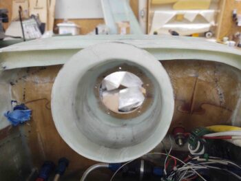
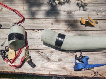
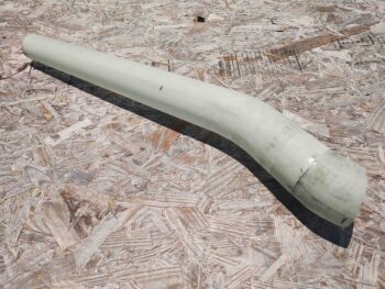
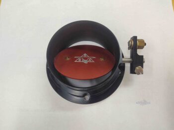
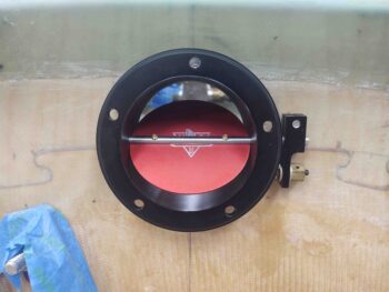
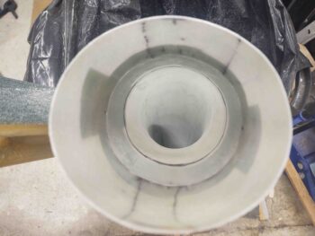
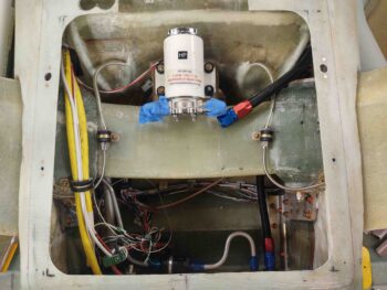
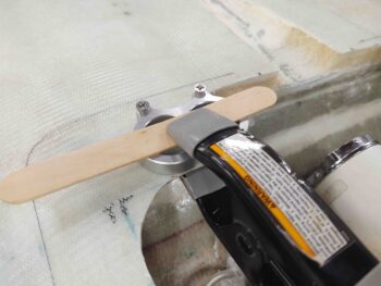
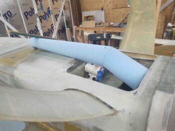
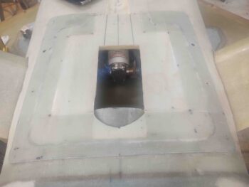
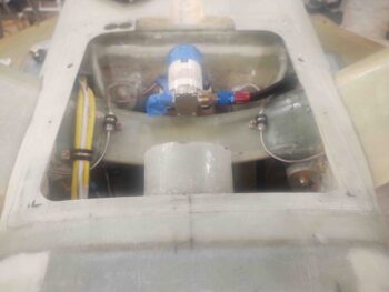
I didn’t want to miss this photo op to place the nose of the RAM air can into the aft face of the firewall and get a shot of it through the open aft RAM air scoop section.  Yes, I placed it upside down not only for a better visual of the logo (Rod Bower’s RAM air can) but for better lighting and ability to see the butterfly valve.

I will most likely start out flying with the lip of the RAM air can poking through the firewall as it is here. One reason I wanted the aft hell hole-mounted part of the RAM air scoop to be as short as reasonably possible was to allow me access into it for adding and testing different versions of 3D-printed or machined Bellmouth-style entrance lips around this original RAM air can inlet, which was designed to have a 3″ SCAT/SCEET tubing attached to it.

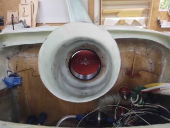
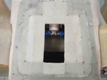
With all the hell hole proper glass now completed, I will turn my attention to working hard to finalize the install of the RAM air scoop into the hell hole hatch cover.

Chapter 24 – RAM air scoop install

I was not looking forward to the first task of the day! But I knew it had to be done to move forward… another one of these right-of-passage tasks that are so common in a Long-EZ build.  Only this one was self-inflicted.

Sigh.

I started out by slowly getting a flat metal blade and a larger knife down into the space between the aft RAM air piece flange and the aft opening of the front RAM air piece. And although I didn’t want to do it, I needed a way to soften up that tape…. so whatever area I got the knife into, I poured a couple drops of Goo-B-Gone on each side of the blade, where the edge was pulled away just a hair.

That actually did the trick.  It softened up the tape enough were I could then manipulate the knife until I eventually could get the knife all the way around the flange/scoop assembly… somewhat like an old style can opener.

However, that was just phase 1.  When I tried every which way to cajole the aft piece out of the front section, it just wasn’t having it.  I tried using strap wrenches to twist the two parts in opposite directions… no joy.  I realized that most likely the only solution was pulling the flanged aft piece “straight” out of the front section.

I wrapped up both sides with a decent amount of Gorilla duct tape to give my tie-down straps an edge to grip to.  I added some cardboard under the tie-down straps so as not to damage the RAM air scoop pieces.

I then tied off the tie-down strap attached to the long end to the back of my trailer.

And attached yet another tie-down strap to the one securing the short aft RAM air piece. I ratcheted the front tie-down strap just a bit and then started applying heat from my heat gun all around the joint.

I could see the pieces started to slowly separate so I applied a bit more pulling power on the front tie-down strap while continuing what I thought was a spread out judicious use of heat.  In just a couple of minutes the two parts of the RAM air scoop separated somewhat easily using this method.

I then quickly took the tie-down straps off because I didn’t want any possible lingering deformation from the heat I had applied to the flange joint.

Here’s the 2.5″ flange off the aft RAM air piece after I cut it to length and cleaned it up.

Here’s the long forward section of the RAM air scoop.  Note that not only is there some minor physical damage at the aft edge where I had to jam the knife into the tape seam, but also some minor epoxy burnout caused by the heat gun.  I’ll cover up –literally– both of these issues with a ply of BID around this aft area.  The damage is definitely not something that requires any major repair(s).

Here we have the front and aft sections of the RAM air scoop mated together.

And a look from the aft end… not a bad fit if I do say so myself.

And the best part is that this time the two sections of the RAM air scoop come apart WAY easier than before!

After spending a decent amount of time washing the RAM air scoop sections with both Dawn dishwashing detergent and Simple Green to remove as much of the Goo-B-Gone as possible, I then got to work on mounting the RAM air can to the aft face of the firewall.

I started by dismantling the RAM air can and then placing the front nose piece on a piece of scrap paper.

I then traced out the inside and outside diameters of the mounting flange piece, as well as the screw holes.

I then used my paper template to locate and drill holes through the firewall to allow me to mount the RAM air can nose piece, and thus the entire unit, directly to the aft face of the firewall.

If the mounting holes look a little tilted or slanted to one side, it’s because they are due to the butterfly valve actuating rod not being parallel to the horizontal cross mounting holes.  Clearly it was more important to get the actuator rod level since I want the open/close actuator action to happen both vertically, and perpendicular to the rod.

Here we have a shot from the aft firewall side looking through the RAM air scoop.  Note that the bends are so shallow that you can actually see out the front of the RAM air scoop from the aft side, and vise versa.

My last tasks of the evening involved a couple layups, which while somewhat routine as far layups go, were pretty darn significant in my book.

The first layup involved getting the tape-joined RAM air scoop aligned with the centerline of the aircraft, and then securing the very aft edge to the front face of the firewall —in the hell hole— with a flox fillet and 2 plies of BID.

This officially mounts the RAM air scoop into the hell hole, and allows me to then move forward in integrating the scoop into the hell hole hatch cover.

The second layup was the aft hell hole flange just above the RAM air scoop, and was also a 2-ply BID layup.  Once it cures I can then proceed with installing the 2 aft corner nutplates to secure the hell hole hatch cover to the hell hole flanges.  This layup finishes the construction of the hell hole flanges.

Tomorrow I’ll work to finish off the prerequisite steps required to mount the RAM air scoop into the hell hole hatch cover.

Chapter 24 – RAM scoop flange

I started off today by cutting out the foam form for the RAM air scoop aft section.  I then pulled the peel ply, trimmed the front and aft edges and cleaned up the piece.

Here’s a side shot.

My goal in the following layup was to create a 2.5″ flange coming forward off the aft RAM air scoop piece that the front scoop section can slide on/off when being mounted or removed.

After taping up –for glass mold release– the inside lip on the aft end of the long RAM air scoop piece, I then mated the just-glassed aft section to the aft end fo the longer front end of the RAM air scoop and secured it with Gorilla duct tape.

Here’s an inside shot.  Not perfectly aligned between forward and aft sections, but definitely very close enough for what I’m doing here.

And a shot from the outside.

I then laid up 3 plies of BID that overlapped 2″ onto the aft scoop piece for permanent attachment and 2.5″ into the aft end of the forward scoop, over the packing tape.  To keep it as smooth as possible for the air flowing through the scoop, I didn’t overlap the ends of the BID.  I laid in 1 ply first then offset the joint of the prepregged 2-plies of BID by about 180°.  I then peel plied the layup.

Here’s another exterior shot with the 3-ply BID flange layup complete.  Note the shallow ‘S’ curve of the entire RAM air scoop.

Later in the evening the flange layup was cured… and, uh, well, I maybe mighta ought have thought this through a bit better! Ha!

After some feeble attempts to extract the aft piece from the forward air scoop I realized it was going to be quite an effort, and after about 20 minutes I kicked that can down the road until tomorrow.

The layup looks great and the peel ply is pulled… I just need to tackle the extraction and then I can press forward!

Chapter 13/24 – Aft RAM air scoop

I’ll start off with a task I knocked out last night, but forget to put it in yesterday’s blog. I’m adding it here for better continuity of this task subject.

After roughing up the micro with sandpaper in the nose landing light pocket, I used a small brush and some primer sprayed in a paper cup to primer up the micro with a couple of coats.  I then left the primer to cure overnight.

Today I started off doing pretty much the same thing, just with a couple of coats of flat black paint.  Here’s my nose landing light pocket bare foam micro fill patch after primer and paint.  Not bad and this task is complete.

My next task on the nose landing light will be to cut and drill a 1/16″ thick lens to replace the much too thick 1/8″ thick lens.

I used slow hardener on the hell hole left internal flange layup to allow me to knife edge it the very first thing this morning.  My hypothesis paid off and it was just barely pliable enough for me to use a razor knife to trim off the overhanging 3 plies of BID.

A few hours later it was cured enough to allow me to re-drill the four 1/8″ pilot holes for the clecos, and then drill out the #2 spot and mount a CAMLOC (AKA Skybolt) receptacle and then mount a K1000-3 nutplate in the #3 position.

This gives me 2 installed CAMLOCs out the 4 total that will be used on this hell hole hatch cover/RAM air scoop mount.  In addition, the 2 installed screws are out of the planned total of 9 on this entire assembly.

I was planning on moving right into assessing/configuring/shaping/glassing of the aft RAM air scoop piece, but decided what the heck, let’s take just another 20 minutes more and mount the K1000-3 nutplates at each of the front corners of the hell hole hatch cover.

Since I can’t get the solid rivet squeezer back into those corners because of the depth of the flanges and the “underside” (as situated) wall “overhangs,” I had to go with pop rivets to secure these corner nutplates.  Moreover, because of the corner configurations, I went with a straight K1000-3 on the right front corner (left in pic) and a 90° nutplate on the left side (right in pic).

I’ll point out that I couldn’t proceed with the aft corner nutplate installs since I don’t have the hell hole internal aft edge flange glassed yet, which will have glass overlapping onto the side flanges in the aft corners.

I then spent about 1.5 hours working the alignment, angles and overall configuration of the RAM air scoop aft piece that will be permanently mounted on the front face of the firewall in the hell hole.  Once finished, there will be a flange on this small mounted piece of the RAM air scoop that the longer front portion of the air scoop will slide onto for a tight interference fit.

I’ll note that I would like the flange to be on the aft side of longer side of the RAM air scoop for both more clear work space when the hell hole hatch cover is removed and less surface disturbances of the air than with the flange edge facing forward…. but remember, the air scoop continues to gradually expand as it goes aft, so it would be physically impossible to go the opposite direction with the intersection flange.

As it was —and as it continually is in building an airplane— I had to compromise with the shape of this last piece of the RAM air scoop puzzle.  I had wanted the air to be presented to and enter the RAM air can entry nozzle at an exactly straight 0°.  But alas, to get both top and bottom curves situated for a smooth transition, I had to cheat an estimated 5° on the angle.  Again, hard to get perfect, optimized specs in a constrained environment with competing resources (i.e “space’).

Thus, in the pic above you can see I gapped the last piece of foam on both sides —the forward gap with the forward-positioned foam piece, the aft gap would be with the firewall face in the hell hole, about 1/4” on the bottom (as situated, technically the top).

After aligning left/right, up/down, forward/aft and securing the position with nails and toothpicks, I then filled the gap with pour foam.

I then cut and sanded the cured pour foam to a pleasing (curved) shape! ha.

And as I did on the forward section of the RAM air scoop, I added pour foam to the inside curve part of this piece as well.

And shaped it into a nice (IMO) curve.

I then added the very original aft piece, which had the same diameter as the aft end of this plug to allow me to smoothly glass that 1/4″ extension to cover the gap between foam and firewall face.  I then taped up the plug/form for glassing and marked the edge lines.

After measuring the short side curve and long side curve, and the circumference, I then cut my BID to overlap on opposite sides of this RAM air scoop aft piece.  To be clear, these BID plies are ply #1 and ply #3 of this layup, with the middle ply being scrap UNI, just as I did on the longer RAM air scoop section.

I then used a long drill bit holder/extension as a single-sided rotating spit to glass this RAM air scoop aft piece.

I started by applying peel ply to the entire surface of the plug/form duct tape.  The peel ply helps even out and minimizes any irregularities in the surface of the tape, and of course results in a nicer smoother internal surface of the RAM air scoop aft piece.

I then laid up the 3 plies of glass: BID-UNI-BID.  I have to say my measurements were pretty spot-on and gave me almost exactly an inch overlap on both sides.

I then peel plied the external surface of this short RAM air scoop aft piece.  I have to say for as small as this thing is, the glassing of it took about 3 hours start to finish, including glass procurement and cutting.

And as par usual, I then left this layup to cure overnight.


Chapter 24 – HH cover hardware

Today was a fairly light build day, although I did get the left side interior hell hole flange glassed, which took a bit to get it trimmed, shaped, sanded and prepped for glass.

I started off by installing a CAMLOC receptacle in the #2 of 4 hardpoint position along the right hell hole flange.  I then installed a screw nutplate at the #3 position.

Here you can see some of the CAMLOC receptacle and the nutplate, both riveted in place to the hell hole right side flange.  Also note that the flange has been trimmed and sanded to pretty much its final configuration.

Here we have the clecos installed in the remaining positions to give a better perspective of the CAMLOC and screw install to secure the hell hole hatch cover in place.

Here’s another shot of the NACA scoop that will get installed during the final push on the RAM air scoop install.  Today I finally got around to trimming up the edges of the NACA scoop.

Finally, here we have the 3-ply BID layup along the left inside hell hole flange.  After spending a good bit of time trimming the lower wall (as situated, actually upper) glass edge and shaping the foam, I again created a flocro edge along the seam with the lower glass wall.

When I laid up the prepregged glass I overlapped it a bit at each corner end.  And I did add a bit more peel ply on this layup: the aft corner and bit in the middle, but most of it was still left UN-peel plied.

I then left this layup to cure overnight.

Chapter 24 – Hell hole layups

I started today with 3 layup goals… the first was the 4-ply BID layup in the front left corner to beef up and secure the hell hole perimeter flange at that point.  Much like I did on the right front corner, where I mounted the LIDAR radar altimeter,

The second layup was rather entailed.  Not necessarily in the layup itself, but in the prep of the flange area and hell hole sidewall beneath (as situated with the fuselage inverted, technically “above”) the flange.  With not much foam and sidewall real estate along that strip, I wanted to ensure I got every bit of strength possible out of the glass.  To achieve this I created a flox (ok, flocro) fillet along the edge farthest from the opening (just above the blue tape in center of pic below).  Finally, although I wanted this area to be strong as possible I still went with only 3 plies of BID (prepregged for layup) to create a flange with 5 plies total.

I should note the odd occasion that I did NOT peel ply this entire layup, but only a couple of inches at the aft corner where there will be some glass overlap from the aft flange layup.

I then got busy on the 3rd and final layup of the day: the NACA scoop that will be at the aft base of the RAM air scoop bump just forward of where the bottom cowl meets the bottom fuselage.

I had bought a plastic NACA scoop from ACS and attempted to tape it up to use it as a form.  I tried a number of times and just couldn’t get the tape to lay down into the corners as I wanted, so I punted on the tape and merely applied a couple of coats of car wax as a mold release.

I then laid in a ply of 3″ wide peel ply across the aft side and flanges before laying up 3 plies of glass: BID-UNI-BID.  I then repeated the peel ply application on the top side of the layup.

After it cured about 3/4 of the way, I tested the new glass NACA scoop for its releasability out of the mold.  It did not look promising.  Thus, I went ahead and pulled the NACA out of the mold and distorted it quite a bit while getting it out of the mold.

After finally getting it extracted, I cleaned up the plastic NACA scoop that I was using as a mold and then used it –as well as visually– to straighten out the quite distorted, partially-cured NACA scoop.

And here we have the NACA scoop even a few hours later, cured in its appropriate shape.

It may seem like only a few simple layups got accomplished, but each one of the last 2 layups took multiple hours each to prep, setup, cut glass, and layup.

Tomorrow I plan on continuing my hell hole flange layups as I transition into mounting the RAM air scoop.

Chapter 24 – RAM scoop cleanup

I have a few items on my to-do list to accomplish before I flip the fuselage back over.  At first obviously it was all about getting the bottom strake skins laid up. Then it morphed into filling in the aft lower fuselage and hell hole, then the bottom cowling, now the hell hole hatch cover and ram air scoop.

Then came swapping out the button head screws on the landing brake for countersunk screws.  And a bit of work on the nose gear doors.  In addition, as you can see in the following pics I do need to do some tweaking on the landing light, and here specifically in the landing light pocket.

When I configured the landing light pocket in the nose I had kicked off the perimeter of the glass pad –the bare blue wing foam– to deal with later.  Well, now is later.  Clearly I don’t want to leave this bare foam in this state.

So I mixed up some micro and filled in the gaps along the edges of the nose landing light pocket. I’ll rough up the micro later and then paint it black as well.  I also need to swap out the 1/8″ thick landing light lens for a thinner 1/16″ lens, which I plan on doing as time permits.

I then spent nearly an hour cleaning out the blue wing foam from the RAM air scoop.  In addition to the wing foam, I removed the duct tape and peel ply as well.

Here’s a shot from the front opening, then the aft opening, of the RAM air scoop.

I then grabbed some shots of the RAM air scoop set near to its final mounting location.

I then took a bit of time to determine the quantity and spacing of the screw and CAMLOC points along the sides of the hell hole hatch cover.  Since I don’t plan on getting into the hell hole or pulling this hatch cover on a regular basis, I decided to go with only 4 CAMLOCs total and all the rest countersunk screws.  This was in part due to a good conversation with my buddy Brian Ashton that got me thinking that I don’t really need to waste a bunch CAMLOCs for this area down here.

Tomorrow will be July 4th, so I probably won’t get any work done on the bird.  But I plan on hitting it hot ‘n heavy come the 5th!

Chapter 22/24 – RAM scoop glassed

I started off today by pulling the peel ply and razor trimming the edges of the 4-ply BID layup on the front right corner flange of the hell hole.

My plan for the day was to start off by glassing the RAM air scoop, but curiousity got the best of me so I spent the first 45 minutes mounting the nose gear AEX LIDAR laser altimeter on the newly glassed flange.

I first determined the laser altimeter’s mounting position and then clamped the aluminum mounting bracket into place.

Since the laser altimeter is meant for a drone, the mounting screw holes on the bracket were only sized for 4-40 screws.  Wanting something a bit more robust I drilled the holes out to accept #8 screws.

I then drilled countersinks into the flange glass for the screws.  And also marked the position of the mounting bracket on the top of the flange.

After drilling out the lens holes and sanding them to a good diameter, I then mounted the LIDAR laser altimeter unit onto the hell hole perimeter flange.  I also connected up the wiring harness to ensure that the length was good.

Here we have a shot from above the inverted fuselage showing the newly mounted laser altimeter.

I then set the hell hole hatch cover back into place to get a view of the laser altimeter position through the somewhat clear perimeter flange of the cover. I’ll drill and shape the lens holes in the hell hole hatch cover flange once the RAM air scoop is mounted and glassed into position.

I then constructed a spit to both secure and rotate the taped-up RAM air scoop form to allow me the ability to much more easily glass it.

I then spent the next few hours laying up first a ply of BID (over peel ply), then multiple pieces of UNI for ply #2, and then a final ply of BID.

I then finished up the layup by peel plying the entire surface.

I then left the layup to cure overnight.

Chapter 24 – RAM air scoop

Today I started off by getting the last couple of button head screws pulled off of the landing brake and replaced with countersunk stainless steel screws.  Again, I’ll be pulling the landing brake off here shortly when I go to micro finish virtually the entire bottom of the airplane in prep for paint.

Besides the screw swap out on the landing brake, today was all about finalizing the shape of the belly RAM air scoop and getting it ready for glass.  I need a dogleg in the RAM air scoop to bring the air from the scoop –set at an appropriate angle to the oncoming air– down into the hell hole to mate up with the air entry duct of the RAM air can on the front face of the firewall (in the hell hole).  This is obvious in my previous pic from yesterday.

To be clear, I don’t know enough about airflow and fluid dynamics to know if this dogleg, bend, elbow, kink (whatever you want to call it) is a big no-no for what I’m trying to do here. I was discussing the possibility with Marco that since I had to have some curves designed into this RAM air scoop –and that they might negate the velocity-to-pressure recovery I was looking for to increase manifold pressure about 1″ via the RAM air can– I was highly considering scrapping all of it and simply putting a filter hanging off the fuel injection servo and calling it a day.   This was before I even cut the bottom of the cowling to allow the RAM air can to fit in place on the firewall.

Well, luckily I had that conversation with Marco, because he noted that Ary Glantz “does this for a living” as a NASA Engineer and recommended that I discuss it with him.  Great advice and that’s exactly what I did.  As I mentioned before, Ary was very helpful and the bottom line is that Ary’s observations were that the speeds we travel in these birds combined with the somewhat shallow angles of the bends in my scoop, he felt that the pressure drop would be negligible.  He also noted that without a lot of time and money it would be difficult to test by exactly what impact these curves would have and by how much.  Ary noted that even with the bends in the RAM air scoop the positive affects would outweigh any negligible losses.

So I pressed forward.  See?! I actually tried to eliminate a big mod and was talked out of doing so!! ha!

Of course my goal is to attempt to keep a constant increase in width as the scoop widens out as it progresses aft.  To create this first dogleg I simply cut the straight RAM air scoop foam at an angle and then rotated the aft side 180°.

In pondering how to secure the 2 pieces together, and not wanting to mess with micro cure times, I simply used a thin layer of pour foam to act as a glue.  I then mated the sides together and secured them with nails and toothpicks.

After the pour foam cured, I then cleaned off the excess foam.

Here’s a couple more shots of the initial dogleg in my RAM air scoop.

I then rounded the shape on the top side to eliminate the hard angled edge at the dogleg. My next step was to eliminate the negative side of that on the bottom of the dogleg, which of course meant adding in more material.  Again, this is in my attempt to keep the ever-widening angle of the scoop constant as the air flows aft.  Thus, whatever I shaved off the top then gets added back in on the bottom… roughly.

I poured some foam around the bottom half of the RAM air scoop dogleg junction.

And then, as carefully as possible, removed the majority of it to leave just enough to create a rounded curve –both top and bottom– of the dogleg.

I then taped up the RAM air scoop foam form with duct tape to act as a mold release when I glass it.

I then spent a good bit of time actually cutting the glass for the RAM air scoop. I had originally planned on simply using 3 plies of BID but after assessing my BID supply, and realizing that I will have to order yet even more (amazing how much you go through on these birds!) I decided –after finding a nice angled piece of UNI that covered half the scoop– to cobble together a UNI ply from scrap glass as the middle ply.

It was too late to kick off a multi-hour layup on the RAM air scoop, not even allowing for the time I would need to construct a spit much like my buddy Dave Berenholtz did when he glassed his RAM air scoop (thanks for the idea Dave!).

So I decided to narrow my scope and knock out a smaller piece of the puzzle.  I cleaned out the foam and glass under the flange on the right front (left as inverted) side of the hell hole.  I then prepped the foam strip with micro and created a drier micro fillet along the top corner before glassing in a 4-ply BID prepregged layup.  This glass will buttress up that flange and allow me to install the LIDAR laser altimeter that is in integral part of the new gear AEX system.

I then of course peel plied the layup and left it to cure overnight.