Chapter 22 – Hellacious harnesses

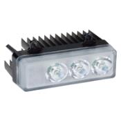
I started off today finishing up the wing lights wiring harness #2 for the wings’ landing, taxi and Wig-Wag lights that will be mounted on the leading edge of the wing anywhere between the end of the wing and the outboard 1/3 of the wing…. with the goal to get them as outboard as possible.

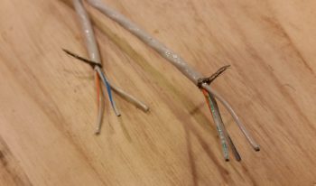
This wiring harness actually involves a 20 AWG 2-wire shielded cable and then 2 external wire runs as well.  On the shielded cable, I started by separating the internal wires and tying all the white wires, white/blue wires and the shield from the 3 separate cables: Left wing, Right wing and panel switch/power.

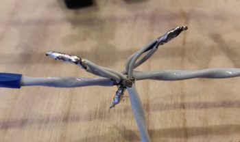
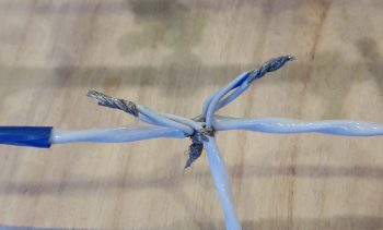
I then soldered spliced the bundled wires.

With the cables in a “T” configuration, it made it a bit challenging to heat shrink it all. So I did what I could on each leg, then used flight line tape around the center axis and secured that with some wire lace.  Yes, Dr. Frankenstein would be proud, but it is secure!

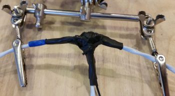
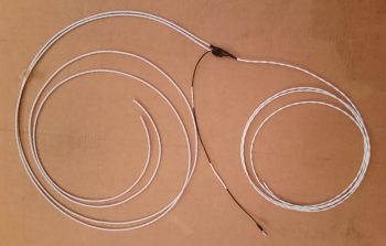
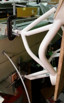
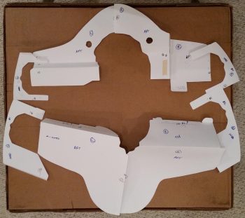
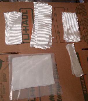
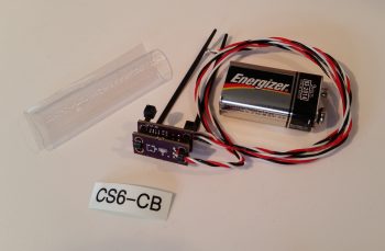
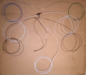
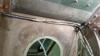
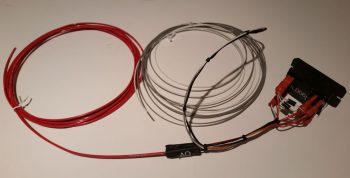
Here’s the end result for the wings landing, taxi and Wig-Wag lights harness.  Along the top is a blue (L) and green (R) wig-wag sync control cable, then the shielded 2-wire cable that provides separate power feeds for the taxi/landing light and the Wig-Wag functions. On the lower side you can see a black wire which is of course the ground wire.  It shares a ground terminal with the shield ground lead from the 2-wire shielded cable.

I should point out that I had a good in-depth conversation today with AeroLEDs confirming my wiring scheme for all my wing lights, and they confirmed that I was installing them in the best configuration for a Long-EZ.

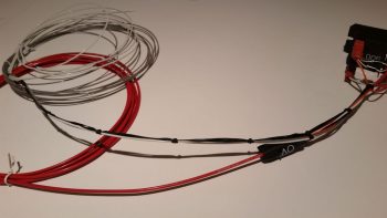
You may also note from the pic below that I spent a bit of time printing out wire labels and affixing them to the wires, both on this harness and on the Nav/Strobe lights harness I made last night.

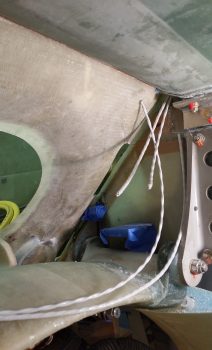
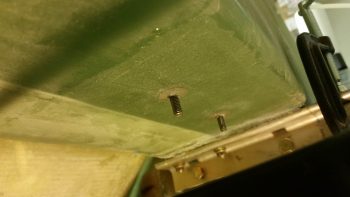
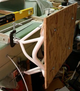
I then grabbed my wiring harnesses and a handful of unattached wiring labels and headed to the shop.  I ran the wing wires up through the holes from the hell hole side.

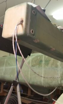
Once the wires were through the holes, I then attached labels for the wires running inside the CS Spar.

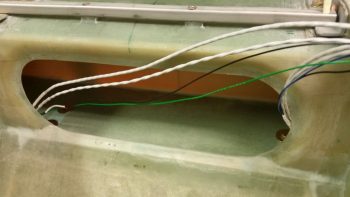
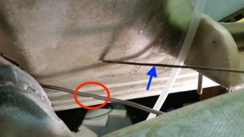
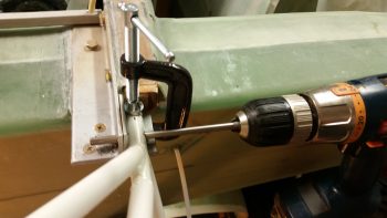
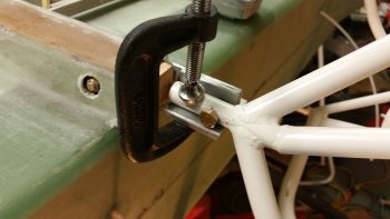
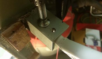
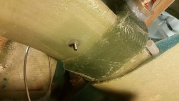
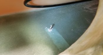
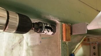
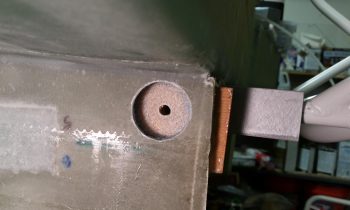
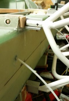
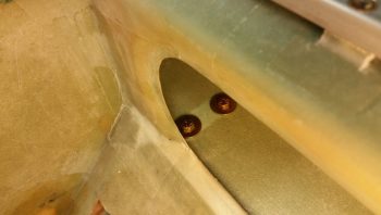
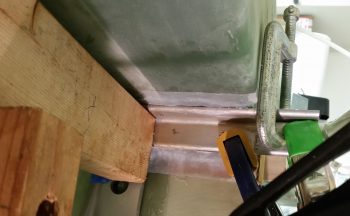
If you look closely, you can make out the wire channel that I drilled through the angled part of the front lower corner of the CS Spar.

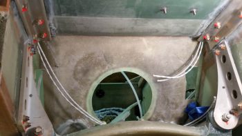
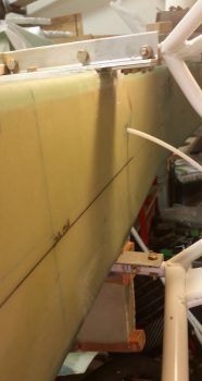
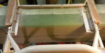
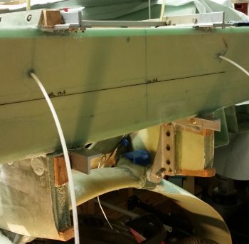
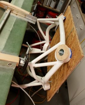
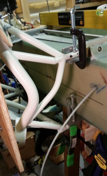
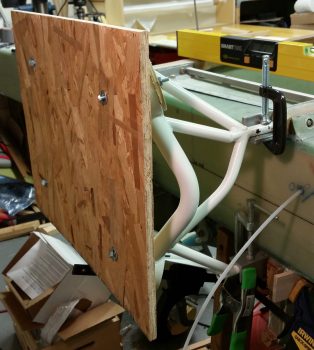
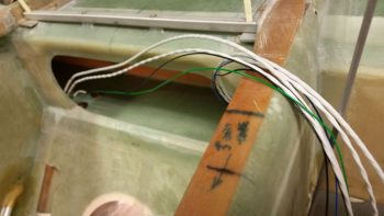
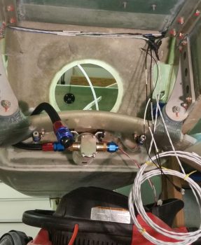
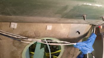
Here’s a Hell Hole shot of the wing lights wiring harnesses from below.

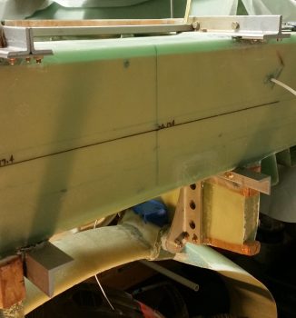
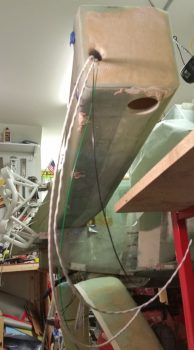
And a taller shot of the wing lights wiring harnesses.  The coiled up wires in the lower right of the pic will head forward to the respective light switches on the panel.

Admittedly, I have a fair bit of slack for the wires exiting out the ends of the CS Spar, especially on the right side.  But better to have a little excess than not enough, eh?

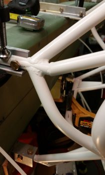
With the wing wiring harnesses in place in the hell hole/CS Spar, then came the questions regarding routing and securing.  I wanted to ensure the wires were routed in an optimized fashion, to include accounting for the aileron control tube that transits through the Hell Hole.

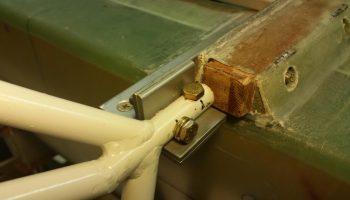
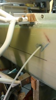
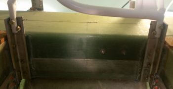
After assessing and fiddling about with possible wire runs and securing options for a good 20 minutes, I finally decided on securing the wing light wiring harness “T” junctions with an Adel clamp set up high on the aft side of the GIB seat back bulkhead, well over to the right side.  Although I had originally planned on keeping the “noisy” wing light wires as far from the “normal” wires as possible, I have accepted why this area has the moniker “the Hell Hole” as there is just not enough space to keep them all separated.  What this means in practical terms is that the upper Adel clamp will secure pretty much all the wires entering/exiting the Hell Hole from the sides and above: both the special “noisy” wires and the “normal” wires.

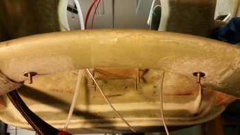
I also added 2 plastic wire tiedown points in the middle and left on the upper seat back. If they look a bit low and askew, well… they are!  When I installed them the wire bundle was higher up (read: in the way) and I placed a dab of 5-min glue in the center of each one.  Well, as I was installing each one, the angle of the seat got the best of me and the original sticky backed pad on each tiedown point caught the seat just enough to pivot the tiedown forward and set it on permanently where it hit.  Yes, this got me on both of the tiedown points… so they sit where they caught the seat! If I screw up, I like to do it twice to confirm that I screwed it up right!! (ha!)  Luckily, they aren’t too low and will work fine.  Thank goodness they’re in the Hell Hole… don’t tell anybody how crappy they look!

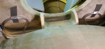
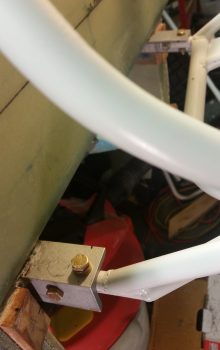
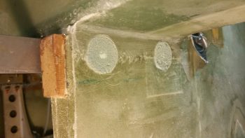
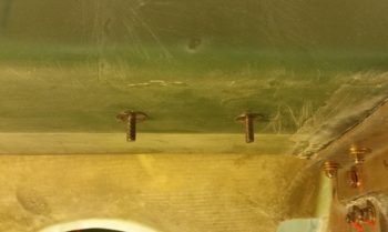
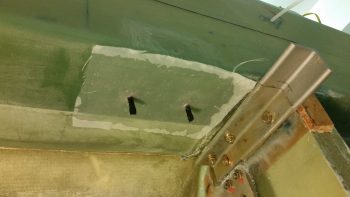
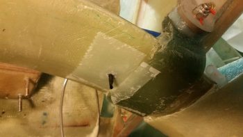
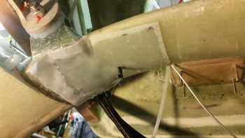
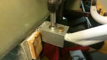
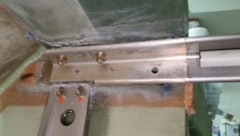
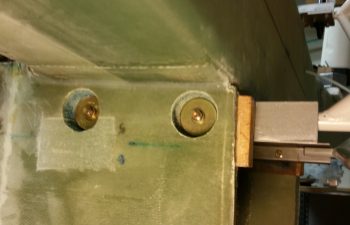
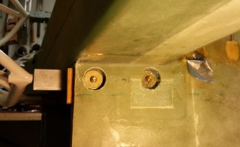
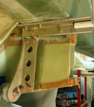
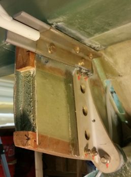
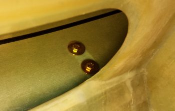
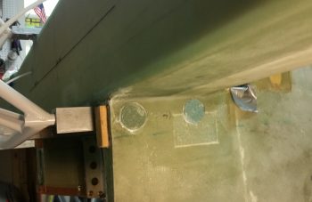
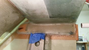
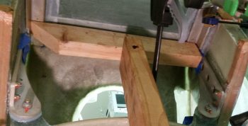
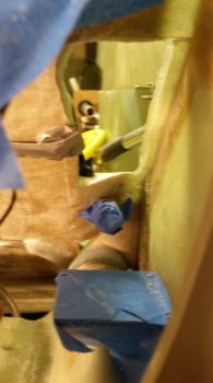
Besides the Clickbond that I bonded/glassed in place high on the seat back for a wire-routing/securing Adel clamp, I also added another RivNut hardpoint a few inches below and outboard (next to the seat access hole) for the same reason.  You can see I floxed it in and taped it into place with gray duct tape.

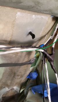
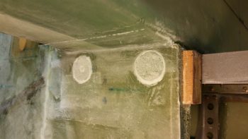
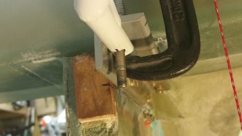
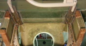
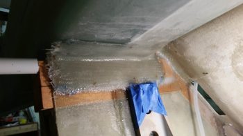
I actually added a third hardpoint with yet another RivNut going straight down in the GIB seat back opening (it’s covered in black electrical tape).  This Adel will essentially be the Gatekeeper for all the smaller wiring transiting into and out of the Hell Hole from the forward fuselage.  With this setup what I’ve done is stay inline with Bob Nuckoll’s advice of keeping the big power wires separated from the little wires since this Adel sits a good 4-5″ above the big power wires coming from the battery compartment.  Of course I will do all I can to maintain this separation the entire length of the fuselage.

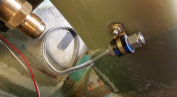
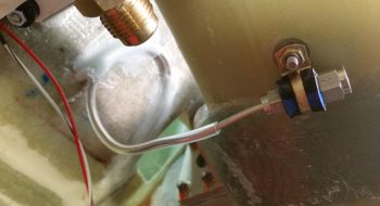
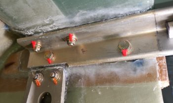
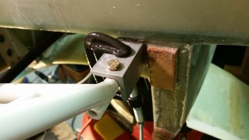
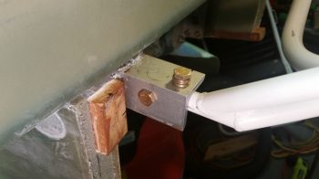
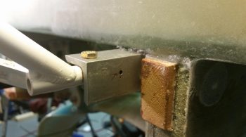
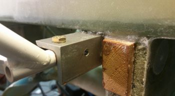
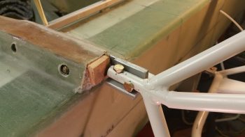
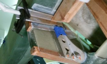
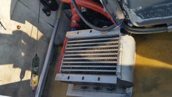
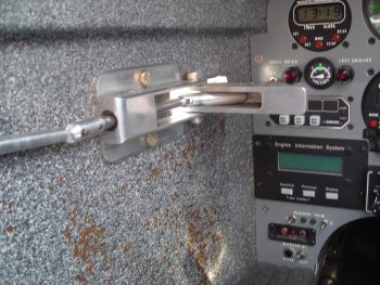
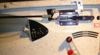
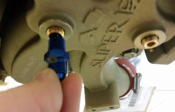
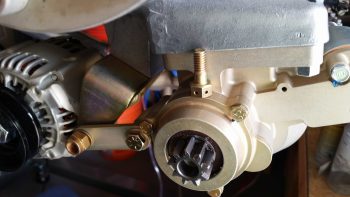
I then got to work on the SD-8 B/U Alternator relay.  My goal was to make the last connection point on the SD-8 a separate removable one for terminating the SD-8 voltage regulator power wire that comes in from the D-Deck/turtleback.  My initial solution was to merely add knife splices to lengths of wires coming from both the voltage regulator and this relay, when an even simpler solution hit me: a double-tabbed PIDG FastON terminal. That would allow me to simply terminate the incoming voltage regulator wire to the relay with a standard FastOn terminal.

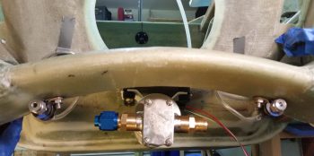
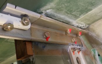
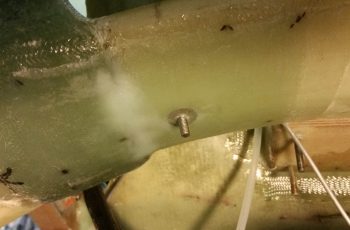
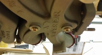
All this is taking place at the furthest right corner of the relay in the pic below, where the bare FastOn tab is visible on the edge of the relay.  Again, this is where the power wire from the SD-8’s D-Deck located voltage regulator will get connected to the relay.

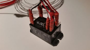
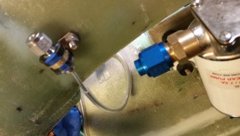
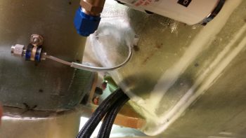
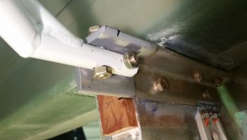
I then prepped the relay wire bundle by securing the Over Voltage module and wire lacing the initial wire runs coming from the relay.

Here’s a closer look at the wire lacing on the SD-8 B/U alternator relay wiring harness.

Tomorrow I’ll label the SD-8 b/u alternator relay wires and continue with my in Hell Hole tasks in prep for installing the firewall.


Chapter 9/22 – Bloody Hell . . . Hole!

I started off today assessing the configuration of all the hell hole components and the wires in, around and through the hell hole.  I did some research on drilling into the CS Spar, knowing that the Spar Caps were sacrosanct, but what about the other areas?  I’ll touch on this later in this post.

I then started my shop tasks today with a small repair.  Yes, hard to believe that any of the 1/8″ aluminum brake line tubing coiled up in the hell hole since 2012 would ever get a ding or scrape on it . . . well, folks, the unthinkable happened!  On my left brake line, about 6″ where it exits the lower fuselage, the tubing had a visible dent/crimp in it (circled in red in pic below).

My goal this morning was to either extricate the dent/crimp and repair the line –without destroying or mangling it– so that it would function as designed, or go with the nuclear option if need be: cut the line at this point and tie in the brake line coming from the wheel farther forward than I had planned.

By my calculations I was dealing with a 0.075″ diameter hole, and I measured a piece of hanger wire that I’d be using at 0.069″ …. Hmmm, seams like it should work (blue arrow in pic below).  I filed the tip smooth and hit it with Acetone to clean it.  But it proved just a tad too thick.  Plus, it wasn’t as arrow straight as I would prefer.

After pondering a bit, Voila!  I found the solution, pressing a perfectly straight and slightly narrower TIG welding rod into service.  I marked a point on the rod that was past the offending dent in the line, and slowing worked the rod, and aluminum tube, to get the rod though the tube and remove the pinch in the line.

Here you can see I’ve reached my mark, denoting that the 1/16″ welding rod is clearly past the offending pinch in the brake line.  I then worked the both the welding rod and tube for a good 10-15 min longer just to ensure that the dented section was as opened back up as close as possible to full diameter.

I wanted to institute some service loops for the brake lines and had some initial thoughts about using Adel clamps or some other means to keep the tubes in place.  Not only did I want to keep the aluminum brake line tubes themselves clean in the event I may need to use them for any reason in the future, but I definitely wanted to protect them as well, especially since I do plan on jamming stuff into the hell hole for storage during flights.

I tried Nylaflow but the resulting loops against the lower aft side of the GIB seat back bulkhead proved too tight for Nylaflow.  I even tried working the Nylaflow into a nice loop before placing it on the brake line, but it just kinked on me when the radius got too tight. Looking around the only thing I had on hand was the clear tubing I was using for the engine dehydrator, so I stole a couple of lengths off the line and pressed them into service.

Since the tubing will be out of the sun and under what we Canardians typically do in situations like this –bury it micro and throw a couple plies of BID on top!– I wasn’t overly concerned that it’s not “aircraft grade.”

After the protective clear tubing was in place over both brake lines, I then cleaned  up the ends of aluminum tubing and temp mounted them in their respective reducer fittings.  I then mounted the reducer fittings in their respective Adel clamps. That gave me a starting point to finalize the size and configuration of my brake service loops, which I then taped in place.

Here are Before & After pics of the right side brake line set in place and then with the service loop micro’d and glassed in place with 2-plies of BID . . . I used 2 plies to help protect the brake line against any untoward pinching.  Obviously brakes are quite a useful thing in fast landing aircraft like Long-EZs.

And here are Before & After pics of the left side brake line set in place and then with the service loop micro’d and glassed in place.

A different view of the right side brake line with the service loop micro’d and glassed in place.

Left side brake line with the service loop micro’d and glassed in place.

While the micro and BID layups cured on the brake line service loops, I took a few minutes to mark my lower engine mount extrusion bolt heads, nuts and washers with some orange torque seal.

I then set my sights on getting the wing NAV/Strobe and Wig-Wag lights wiring runs in the most unobtrusive, out-of-site way possible.  As I mentioned at the start of this post, I had done a fair amount of research both in the plans, and online, in regards to drilling holes in the CS Spar.  The results of my research was of course to stay away from the Spar Caps, no drilling through the shear web (which is actually common for the one hole required for the Autopilot roll servo, if used) and remain clear of the extrusion hard point areas.

I’m not sure exactly what #3 is all about since I have no plans on drilling INTO the hard points, but any viable hole for cable runs is going to be within 2″ of the hard points… and that is “in the area” in my book…. so of the 3 sacred “No-drill” rules I found, I’m apparently violating all the but the spar cap rule.

So, in probing around in my hell hole I discovered a spot up in each corner just aft of the CS Spar-GIB seat back intersection where there is sparse glass/flox.  It’s actually the lower angled “bull nose” of the CS Spar and that is where I placed my bullseye for drilling a 1/4″ hole diagonally/aft on each side to run my wing lighting wires from hell hole to CS Spar (or vise versa).  Here’s the result.

Might I say for my friends in the southern hemisphere: it worked a treat!

I then pulled the wiring out of the hell hole/CS Spar and took it upstairs for further processing (i.e. soldering).  I then soldered the left and right CS Spar wing NAV/Strove light wiring together along with the shielded cable run to the light switch on the panel.

I know it’s fairly difficult to see the wires, but I looped them up over my kitchen light with both sides dangling down just to get an idea of how long the wiring harness is that we’re dealing with here.  And this only gets out to the end of the CS Spar.  The internal wiring that goes through the actual wings is yet to come!

Here’s the completed wiring harness for the wingtip NAV/Strobe lights.  It’s late so I stopped on this harness, but I will also have wing tip (or outer wing let’s say) mounted landing/taxiing/wig-wag lights as well, which I still need to make up that harness for.  BTW, the left/right CS Spar portion of the wiring is on the left in the pic below, the black ground wire will tie into the “Forest of Tabs” in the hell hole, and the wire bundle on the right goes forward to the switch on the instrument panel.

Tomorrow I will continue with my Hell Hole shenanigans to the point I’m comfortable with closing up the major access to the Hell Hole by installing the Firewall.


Chapter 23 – Engine Mount Installed

I feel like I have a cat now because I started off the day skimming the top layer of pink desiccant out of the engine dehydrator container (just like the proverbial kitty litter box).  I also pulled initially 2, then 3, engine dehydrator plugs and swapped out their pinkish desiccant for nice deep, rich blue desiccant.

Here’s the third and last engine dehydrator plug in which I swapped the desiccant out.  I placed it on the bed of pink desiccant that I was just getting ready to pop in the oven for an hour or two at 240° F.  Not pictured are a half dozen desiccant bags I pulled out of the engine’s exhaust ports and air intake plenum to also dry out as well.

After the desiccant returned back to its brilliant blue color, I dumped it back into the engine dehumidifier tub and replaced all the desiccant bags.  Before I did all this my engine was at 21% relative humidity internally, and about a half hour after I finished with my desiccant shenanigans it was back down to 12%.

In the movie So I Married an Axe Murderer, Mike Myers has a line where his character states to Nancy Travis that he believes that “all Scottish food is based on a dare.” Well, sometimes I feel that way about building Long-EZs: that all majorly important steps are based on huge dares, fraught with the exacting fear that if you screw it up… well, really bad stuff awaits.  Like major rebuilds or just parting with a lot of money to fix it.

The biggest two build dares that come to mind involve drilling: First, drilling the wing bolts through the CS Spar into the wings has got to be the biggest right of passage on a Long-EZ build… simply crazy.  Second, is drilling the engine mount bolts into what is supposed to be 5/8″ engine mount tubes (I just extrapolated this info from a conversation I had with Dave B!) whereupon mine are actually 9/16″ in diameter… let me tell ya, in this situation that extra 1/16″ might as well be an added meter on the target!

Ok, here’s another odd statement that is probably rarely heard: So I fixed my “loose” bolt hole drilling problem by swapping out my REAMER for just a standard 1/4″ DRILL BIT. Crazy? Yes. True? You betcha!

When I drilled out the vertical bolt hole in the lower right engine mount I used a 1/4″ drill bit for the final 1/4″ hole.  The fit was way better than the 1/4″ reamer since it took a bit of finagling to get the bolt to go into the hole.  Woo-hoo!

I then drilled the horizontal bolt hole in the lower left engine mount to finish off that position.

I again calculated the midpoint of the engine mount tube and the 3/16″ thick engine mount extrusion and drilled from the outboard side in.  It worked a treat!

I then had 5 of the 8 bolt holes drilled . . . nearly 2/3rds of the way finished!

As with an alternating clamping process of attaching something into place that has a lot bolts or screws, my next engine mount tube to be completed with the drilling of the second bolt hole (forward/vertical here) was the top right position. Clearly on this one I was able to drill straight into the engine mount tube itself.

I then jumped back down to the lower right engine mount to drill the forward side horizontal bolt hole.  I started with a 1/8″ starter hole as shown below.

And ended up with a 1/4″ bolt mounting hole.  Again, after the initial go with just using the 1/4″ drill bit, the reamer went back on the shelf…. the 1/4″ drill bit simply did the job in stellar fashion.

Here we have the finished engine mount bolt holes on the right side:

Of course finishing off drilling the lower right engine mount bolt holes meant that both lower engine mount bolt holes were completed.

Yes, not a great pic, but the best I have for viewing the fitted temp bolts on the lower engine mounts.

I then finished the engine mount installation by drilling the vertical bolt hole on the upper left engine mount tube.  Both this bolt hole and the horizontal took significantly longer with quite a bit more effort than any of the others, because remember in this position the engine mount extrusion is 4130 steel (which may help explain why it’s so much narrower than the other engine mount extrusions).

Here’s a shot of the top engine mounts with the bolt holes all drilled.

I then double-checked my slightly modified angle and, again, using a 0.224″ spacer (drill bit) vs the plans 1/4″ (0.25″) spacer, I was at exactly 90° [Note that although the board is in place on the engine mount, I am measuring the angle with my contact points for the level and spacer positioned on the board as if there was no board present].

Bam Baby!  90° on the nose . . . now that’s the money shot!

Here I will regale you with a plethora of officially installed engine mount pics!

Tomorrow I’ll be doing a fair amount of work in the Hell Hole in prep for the installation of the firewall that should be taking place within the next 3-4 days.


Chapter 9/22/23 – Engine Mount Install

Initial engine mount install that is…

I started off today by trimming down and then rough sanding the foam plugs that I have micro’d in place over each outboard end of the lower extrusions’ bolts, nuts, and wide area washers…. for both the right and left sides.

I then removed the engine mount –which is a tight fit– exposing the 4 engine mounting extrusions.

here’s a closer look . . .

Using the taped up SD-8 relay and some 5-min glue, I mounted the 2 SD-8 relay Clickbonds on the underside of the CS Spar towards the right side a bit.

When I was making up my 3×5 card task list this morning, I also decided to verify my desired locations for the right and left brake line runs.  I wanted them below the main gear so they were as accessible as possible via the bottom Hell Hell cover (disguising itself as an intake scoop) once the plane is completed.

I confirmed the positions and sanded down the areas that would get a few plies of BID to secure the Clickbonds into place.  BTW, the Adels that are getting mounted to these Clickbonds won’t directly clamp to the brake lines, but rather will secure each side’s 3/16″ (from the wheel calipers) to 1/8″ (fuselage brake line run) Generant reducer fitting.

As the 5-min glue set, I then prepregged all the BID for laying up over the Clickbonds. Just before mixing up some epoxy with fast hardener, I wrapped each Clickbond threaded post with a small piece of electrical tape to protect against any epoxy gunk.

I then laid up 3 plies of BID over the SD-8 Relay’s Clickbonds and then peel plied it.

And did the same for the right & left side brake line Clickbonds.

I then got to work on drilling the engine mount bolt holes.  I had an entire plan of drilling the engine mount with it off the extrusions, since I was thinking there wouldn’t be enough clearance for a drill to get a straight shot at drilling the bolt holes.  There may not be enough clearance for the bottom horizontal bolt holes, which are forward on the bottom, but for the top horizontal bolts (which are the aft positioned holes) there’s plenty of room.

Also, instead of messing around with some inherent induced error by measuring from F28 or the panel, I went straight to the tip of the extended pitot tube to measure the final position for the top engine mount cups to get them both at F.S. 134.2 AND equidistant from the very front tip of the plane [to be clear, I did FIRST confirm F.S. 134.2 from F28 since I needed a known F.S. to measure off of].  I’m fairly certain I’m off maybe 1/32″ at the most… maybe, maybe just a hair higher if we account for any flex and angle of the measuring tape, but definitely close enough that “these dogs will hunt!”

After drilling a very small pilot hole just enough to guide a larger bit, I switched to a long 1/8″ drill bit for the initial round, then stepped up a couple bit sizes each round.  Of course, going through 4130 took a bit for the initial hole, but went smoothly after that.

Here’s the break through on the right side.

And the left.

I then used a 0.25″ reamer, that actually measures out at about 0.246″ on the calipers. Perfect, I thought, but there was no resistance to the bolts when I slid them into the bolt holes.  Disappointing, but follows in line with what my buddy Dave Berenholtz experienced when he drilled his engine mount holes down in OZ (And here I just thought it was a hemispherical gravitational thing on his part . . . ha!)

Here’s the nicely aligned but not-as-tight-as-it-could-be bolt test fit in the upper right engine mount horizontal bolt hole.

And let’s not forget the left side. Same story.

I don’t have any pics of my next task, but with my top horizontal bolt holes drilled, and thus the top side of the engine mount configuration locked in, I spent a good half hour aligning the bottom engine mount tabs (using a squeeze-handle style clamp) so that the engine mount aligns leaning forward 2° at the top, which is the plans position.  Again, however, the plans was set up with a 118-125 HP O-235 motor in mind, while I’ll be pushing 180-190 HP.

However, after rereading Dave B’s account on setting his engine mount, I realized that I had misread what my fellow Long-EZ builder had ascertained about the translation of the 2° figure.  So, in the end, knowing that I wanted the aft side of my engine just a hair lower than that of an O-235 Long-EZ, I replaced the typical 1/4″ spacer at the top the engine mount when measuring for this 2° angle (derived during the build by setting the plans F.S. for the bottom mount at 134.45) with a drill bit 0.224″ in diameter.  This engine mount angle and alignment is of course checked by getting 90° on the level with the bottom against the engine mount and the spacer wedged in between the level and engine mount at top.

Once I dialed in my engine mount angle, I clamped the engine mount tubes to the lower engine mount extrusions.

I then started drilling the bottom left engine mount vertical bolt hole, which again, the aft bolt holes on the lower mounts are vertical.  I marked my hole from below, and again drilled just enough of a small starter hole to align the bit.  However, that experience alone told me there was no way I was going to drill a hole UP through 4130 for as long I would need to break through this thick steel tube.

So I carefully measured out the tube centerline and extrapolated all that data up to the top of the engine mount extrusion, and drilled from the top down.  Ahh, much easier!

I did use the reamer, not surprisingly with the same underwhelming results as I got on the top side bolt holes.

However, I decided to add a new twist (this is a pun . . . you’ll see!) to the lower left mount tube’s vertical bolt hole by getting the bolt hole just slightly off center.  The “twist” reference above is because the actual engine mount extrusion is slanted just a hair inboard at the top.

Thus, when I drilled straight down I was in fact relationally at an angle on the lower engine mount tube.  Not far enough off center to cause structural concern, especially with this super strong and rather forgiving 4130 steel, I just lose some major style and good craftsmanship points for this “infraction.”

I then grabbed a quick dinner with an old military buddy of mine and when I returned I pulled the peel ply off all my cured Clickbond install layups… which all turned out pretty good.  Here’s the SD-8 relay mounting Clickbonds on the underside of the CS Spar.  BTW, I positioned these forward enough to be out of the way and not induce any added hassle when I layup the corner BID tape between the forward side of the firewall and the CS Spar

Here are the cured BID layups for the lower right (upper pic) and left brake line securing Clickbonds.

Tomorrow I’ll continue with my engine mount installation, although I will need to assess my reamer issue.  I think I’ll try drilling out the lower right extrusion’s vertical bolt hole with just a 1/4″ bit and see what kind of result I get (obviously builders have been doing this for years with no reported adverse affects).


Chapter 14…. finally complete!

Well, after about 6 years I finally finished Chapter 14!  Woo-hoo!

I started off by drilling the aft vertical bolt hole on the lower left engine mount extrusion up into the Spruce hardpoint that is imbedded in the CS Spar at all the extrusion attach locations. I double checked my marking that I had made a couple of days ago and then took the plunge!

As you can see, it popped through inside the CS Spar at the tail end and center mass in the Spruce hardpoint.

And I got the same result on the right side as well . . .  I was definitely starting off the final step of Chapter 14 right with the first bolt hole attempts.  Since these 2 bolts are situated so close to the CS Spar’s critical lower spar cap, I knew after I avoided hitting it that the bolt installs would only get easier from there.

Then, out of nowhere, as I working in the Hell Hole, minding my own business . . . Bam! An early casualty . . . ahhh, precautionary tale: THIS IS WHY I PEEL PLY!!
[Obviously this was in an area I couldn’t reach to peel ply!]

After getting the vertical bolts installed, and just as I finished drilling the aft side hole in the lower right engine mount extrusion, it hit me that I was forgetting something!  Ahh, Terry Schubert would be sooooo ashamed if I forgot to seal the wood inside the holes!

So I pulled out the front vertical bolt on each side and left these aft side holes (I had already drilled the outside access for the wide area AN970-4 washers… below) open.  I then mixed a small batch of epoxy with fast hardener, added a bit of alcohol to it to thin it out, and then used Q-Tips to get the epoxy slathered onto the bare Spruce inside each hole.  I also treated the holes in my longerons for my rollover assembly.  I then went upstairs and cooked a fairly quick dinner, took a break, sat down and had a bit to eat.

When I got back the alcohol-epoxy solution was just starting to gel slightly.  So I installed the 2 pairs of bolts into the open holes, pulled the aft vertical bolts and hit those holes with the sealing epoxy solution.  I then drilled the front side bolt holes on each side.  It took a while for me to drill out the front holes, so a bit after I was done I hit the forward pair of the side holes with the alcohol-epoxy solution and then replaced the aft vertical bolts.  Wood holes sealed!

Backtracking a tad, here I’m drilling just the outer sidewall skin and a bit of the foam in order to remove the plug . . .

that would allow me to create a nice inset to employ an AN970-4 wide area washer in an area –the exact area as the gear mounts in fact– that is just fiberglass over Spruce. Knowing the issues I had with the narrow washers and bolts digging into the glass & wood, deforming both, in my original main gear mounting, I definitely want to avoid that where my engine mount is concerned.  Thus, just as I did on top extrusions, I’ll again be using AN970-4 wide area washers.

I then mounted both sets of side bolts for the left and right lower engine mount extrusions. I will note that the forward bolt overlaps about a third-to-half of the way into the area that I dug out to install the wide area washers for the top main gear bolts, as is easily seen in the pics below.  Again, since the underlying glass and wood was deformed a fair bit on the main gear outboard bolts, I used a bit of flox and BID to add some structural integrity and solid underlayment for the gear wide area washers (again, this was for the main gear bolts).

I said all that to merely state that, unlike the aft extrusion bolt, each of the forward bolt’s washer has a lopsided “floor” or “wall” to rest upon since theres a build up of glass and flox on the bottom side of each hole.  To remedy this, I simply added a bunch of thick flox behind each of the 2 forward extrusion bolt washers.

While the flox was curing (I used fast hardener of course) in the forward side pair of extrusion bolts, I took the opportunity to snap some pics of the completed install of the lower engine mount extrusions . . . thus completing Chapter 14!

Here’s shots of the interior bolts (4 each) of each side of the lower engine mount extrusions.

And a shot of the whole shebang!

It’s rather interesting how actual little info there is on this step in the plans.  Knowing I didn’t want a huge gash on my arm as I stuffed goodies into the stowage access hole of the CS Spar before a flight, I decided to mount the vertical bolts with the heads inside the CS Spar and the threaded arm-mangling part of each bolt on the bottom (Hell Hole) side.

I should say that I’m really happy with hitting the CS Spar’s embedded hard points.  I did very slightly cheat on the front bolts and moved them aft around 0.070″ to 0.1″ to ensure they were on the flat part of the spar (both top and bottom on the front of the CS Spar has an angled corner).  This also helped ensure that I could fit a AN970-4 wide area washer in these locations as well.

After the flox –serving as the AN970-4 leveling base in the front side holes– was very close to being cured, I snugged down all the side bolts just a pinch and then micro’d in foam plugs I had just made specifically for this purpose.

I’ll let these dry overnight, then sand them flush with the sidewall.  However, I probably won’t glass them until I build the strakes and add a bit of glass and Kevlar to the sidewall area near the main tank fuel flow feeds that are embedded in the fuselage sidewalls.

Here’s the tally on how many plies I used on each engine mount extrusion BID pad.  As you can see, I met the 7-ply minimum criteria spelled out in the plans.

Tomorrow my main goal is to get the engine mount drilled and mounted onto the engine mount extrusions.  After I finish that task I will then install the engine mount onto the engine and then start planning on exactly how to attach that whole monstrosity to the engine stand.


Chapter 14 – Lower extrusions installed

Today was all about getting the lower engine mount extrusions installed.

I started off by checking the firewall to see if it was 90° vertical, which of course it wasn’t.

The front tire was really low, so by adding air to get if full, and adding one small piece of 3/8″ wood underneath, I got the firewall “zeroed” at 90°.

With my firewall dialed in at 90°, I then removed it and clamped the engine mount in place on the upper engine mount extrusions.

I then checked the plate that I bolted to the firewall last night.  With just a scant bit of downward pressure I can get it to my targeted 1.4° slant with no real difficulty.

Over the next couple of hours I then floxed in the 2 WA16 Spruce wedges and covered both of those –respectively– with 2 plies of BID that covered the entire WA16 and overlapped onto the sidewall, spar and back seat.

I then added the remaining plies of BID to the lower engine mount extrusion pads, 9 plies on the left and 8 plies on the right.

Here’s a pic of the right side WA16 floxed in place with the associated BID laid up in place.

And here’s the same on the left side.

I then slathered up the just glassed BID pads with copious amounts of flox, applied fresh epoxy to the mating surfaces of the lower engine mount extrusions, and then set & clamped them into place on each side.

I then used a pre-cut 2×3 with a wedged 2×4 to keep the forward side of the lower engine mount extrusions pressed up tight against the BID pads.

I then double-checked that all the dimensions were good.  Here’s the right side lower engine mount extrusion in place.

And the left.  As you can see, I peel plied all the BID pad edges that were lined with flox for a nice smooth edge.

Here we have the installed lower engine mount extrusions, shown from the left side.

And the same thing again from the right.  It took me about 6 hours total to finish this step.

Tomorrow I’ll drill the holes through the lower engine mount extrusions to then bolt each on to the CS spar and lower longeron piece.


Chapter 14/23 – Baffling Extrusions

Within a day of coming back from NC I started feeling a bit sluggish, and felt a cold coming on.  Well, today it hit me pretty hard, so I’ve been moving at a bit slower pace.  I’m hoping tomorrow I’ll feel well enough to get the lower engine mount extrusions glassed into place.  On top of all that, when I woke up this morning it was a virtual winter wonderland outside, with snow continuing to fall and a good few inches already on the ground.

So I grabbed a cuppa and went through Mike Beasley’s baffles and –while looking at his website– taped a number of the pieces together to get a good idea what his were all about.

The initial confusing part on his just looking at them is that all the annotated & marked sides are actually the interior side of the baffles, with the blank sides ending up what you see when you piece them together, or the exterior side.

So once I got that little tidbit down, I was able to get a good handle on what was going on.  Here’s the inside (looking aft) of the lower skirt that wraps around the alternator & starter.

Here’s the top looking aft.

Now, since I’ll have my oil cooler in the plans location on the side of the engine and not nestled in the aft underside region of the motor, I won’t need the aft lower skirt positioned like Mike’s (and countless other EZs) so far aft that it just barely covers the aft end of the alternator and starter.  Here’s Marco’s oil cooler in the plan’s location, just forward and to the left of the motor.

Here’s Mike Beasley’s real world baffles, with the lower baffle skirt far aft to account for the oil cooler placement.  If I were going to place my oil cooler in this location, I think it might have been a better, cheaper option to just use Mike’s Beasley Baffles.  From what I can tell Mike really did a bang-up job on his baffle templates, so they are certainly a viable option for most builders that are installing an O-320.

That being said, here’s a lower baffle skirt placed much farther forward that has both the alternator and starter exposed, but still has a centerline mounted oil cooler.  My baffles will look more like this, only without the oil cooler mounted in the centerline position.  So in my situation I think it will work out better having the VANs baffle kit on hand to modify.
(To be clear, I will be using Mike’s baffle temples extensively –as I have been doing– to modify the VANs baffle kit).

I then compared Mike’s baffles to the VANs, and assessed what I would need to modify on the VAN’s baffles.  On the set of side baffles (bottom of pic) you can see my proposed line cuts off that big blank piece of aluminum, which would be on the aft side.

This expanse of baffling would normally match up to the considerably wide shelf going aft of the cylinders (see 3rd pic from top, above) and which then drops down to create the skirt running across the aft faces of the alternator and starter.  Here’s another example on Mike Beasley’s bird.

Again, since my lower aft baffle skirt will be located forward of the alternator and starter, I only need a very narrow shelf just aft of the rear cylinders to then drop down to create the lower baffle skirt.  Here’s a good depiction of what I’m talking about on Buly Aliev’s Cozy, where he used the VANs baffle kit.

I then made it down to the shop to get a little bit of prep work in for installing the lower engine mount extrusions.  I copied Dave Berenholtz in bolting a wood plate to the engine mount to help easily ascertain the mounting angle of engine mount/engine during the installation of the lower extrusions.

Here’s another shot.  BTW, the plans would have you install the engine mount so that the prop is 2° higher than the front (firewall side) of the engine.  This makes sense since the Long-EZ, like many aircraft, flies about 2° nose high.  However, remember that the 2° number is based on a 118-125 HP Lycoming O-235 engine.  If you’re pushing a few more ponies, which I and most people are these days in Long-EZs, then it takes less angle to keep the nose up.  Also, 2° high on a higher powered engine probably won’t get you level flight, but a slight climb… which then of course would mandate more trim forces in play.

For example, with a planned 220 HP engine, my buddy Dave B. set his angle at 1.1°.  So for my 180-190 HP motor, I’ll be setting my engine angle around 1.4°.

In addition to fiddling about with the baffles, I also tweaked the lower engine mount extrusions install plan and will hopefully get these guys glassed in tomorrow, or the next day (depending on how I feel of course).


Chapter 14 – Lower engine extrusions

This morning, as it was raining and sleeting outside, I decided to let the shop warm up a minuscule amount before heading down.  So I started off my day by creating yet another tab on my Excel build tracking spreadsheet to compile all the pertinent engine torque values.  This endeavor involved calling a couple of companies, one being B&C, to obtain/verify torque values on their products.  In addition, some of the engine torque values were shared with me by master engine & Long-EZ builder, Chris Seats.

In other news, over the past couple of weeks I have decided to undertake yet another mod (I know, I know . . .!) and build a new canopy latch based on Mike Bowden’s design since his high horizontally-situated/activated latch works much better for my configuration (read: operating space) than does the rotary latch extending down in front of the left-side panel.

Although based primarily on Mike Bowden’s design, I will combine it with the forward latch catch manipulating features of the mystery Long-EZ that I somehow have a pic of, but have not been able to find who owns it or built it.  Coincidentally, as I was compiling a buy list of all the materials I would need to construct this latch, I got a text from Mike Bowden… who graciously provided me a plethora of dimensions that I had asked him for regarding his canopy latch.

It being a very cold day outside, I also decided to do some more assessments on oil heat fittings and firewall pass-thrus before adding them to the buy list as well.

I then finalized updating/verifying the numbers on my lower engine mount extrusions install diagrams that I whipped up in PowerPoint a couple of years ago.  I also did an inventory on the glass I had cut out about a year and a half ago (IIRC). Although it was prepped for being merely wet out in prepreg and then cut, I decided to cut it into its separate component pieces.  I then had to carefully move the engine-on-hoist out of the way so I could then drop down the glass cutting table to then cut some more BID to finalize the glass prep for glassing-in/mounting the lower engine mount extrusions.

Since my fuselage is just a hair wider at the bottom (talking around 0.1″) I decided to forego the “standard” bottom engine mounts of 1/8″ thick by 1.5″ x 1.5″ 2024 angle for ones that are slightly more robust (i.e., take up the gap with aluminum vs glass) at 3/16″ thick with 1-1/4″ x 1-1/4″ legs.

Any longer legs on the engine mount extrusions other than the 1″ stock seem to need some trimming to lessen the height right at where it meets the main gear extrusion. This is so when the thick pad of BID that the extrusion gets mounted atop of (technically below on the bottom extrusions) there is some wiggle room for the engine mount extrusion to get pushed further from the CS spar and more towards the main gear mount extrusion, while avoiding any unwanted collisions betwixt the two.

Thus, for the area of the vertical leg on each lower engine mount extrusion, I removed about 0.2″ at the lower edge.  Again, just for the area immediately above the main gear mount extrusion.  I started by marking the engine mount extrusions.

Then clamping each one to my work bench –with the help of 2×4 underneath the angled aluminum to stabilize it– and used my trusty Skil saw to trim it down.  Worked a treat!

I then cleaned up each thinned out area with a hand file.

After sanding the outboard and top sides of the extrusions that will mate up to the BID pads and flox with 220 grit (as per plans), I then washed the extrusions down in warm water and Simple Green.  I then took them upstairs to mark up the bolt hole locations in accordance with the plan’s dimensions.

To ensure I don’t lose my bolt hole locations with Sharpie-destroying/blurring epoxy (after I double-checked all the measurements!) I took my drill with a small bit and drilled the slightest of a hole beginning at each mark.

It was getting late, but still wanting to get as much done during this very cold spell of weather we’re having, and to free up as much time as possible during the upcoming good build weather (if it ever comes! ha!), I decided to cut out my Beasley Baffles templates that were created by the benevolent Mike Beasley.

If you remembered that I purchased a 320 engine baffle kit from VANs Aircraft, you’d be correct.  So you may be asking why I need to cut out the templates from the ones Mike B. so graciously (yes, a lot of gracious canardians around . . .) provided me.  Well, the VANs baffles would be a great direct use-as-advertised item if I was building a tractor, top-down cooling airplane with an RV style cowling.  But clearly I’m not.  So although the VANs kit will give me a huge head start on the engine baffles, it will not be without a good amount of modification to get it all to fit and work.

That’s where Mike’s Beasley Baffles come into play.  Since his baffles are specifically for a 320 in a Long-EZ, it allows me to dial in my baffle design much, much closer by using these templates to modify the VANs baffle kit as needed.

As a reminder, Mike sent me his Beasley Baffles via email in electronic form a bit before RR last year.  I then took the 3 files down to Staples and hand them printed out on card stock. As for tonight however, it took a good hour and a half to cut these baffle templates out of the card stock.

When I went upstairs to grab the Beasley Baffles to cut them out of the card stock, I also grabbed the outline of the firewall I had traced onto 2 large pieces of scrap paper I had.  I cut & taped the firewall outline together for a real size version of my firewall that will help in determining the final layout and configuration of all the firewall components.

It’s supposed to snow tomorrow, so I’ll assess next steps in regards to installing the lower engine mount extrusions either tomorrow or the day after.  In the meantime, I’ll continue to work any tasks of opportunity that are good for rainy day tasks that I don’t want hanging over my head when the good build weather finally arrives.


Chapter 22/23 – Engine Parts? Check!

I understand that buying stuff for the airplane is not necessarily building.  However, at the risk of sounding like a broken record, the research & collaboration that goes into deciding what to buy is often lengthy, in-depth and time-consuming. I realize that I’ve been identifying and detailing a lot of the pieces/parts that I’ve bought over the last month or so, but a lot of that is due to the current cold weather and my downtime during household good move trips/visits to North Carolina.  Again, the fact that there’s so much research that goes into the decision of what to buy is a big reason why I post the items on this blog, because it is actually a big deal (IMO) to first make the decision, then get the item in hand.

With my blogging methodology now fully explained <wink>, I’ll get into the stuff I could do (e.g. aforementioned research & acquisition) during my trip down to NC.

Over the last week I’ve researched flywheels to enable me to pick the best one for my configuration.  To back up just a bit on this story, my initial flywheel conversation during my engine build with Wayne Blackler, Sky Dynamics, Power Sport and ECi (Continental) convinced me to NOT go with Sky Dynamics’ lightweight flywheel, which was my initial flywheel selection.

Over the past few days I spoke with B&C about 7.5″ vs. 9.75″ alternator pulley wheel diameters with them stating that there’s a negligible difference at low RPMs and no difference at normal operating RPMs.  I then again spoke with Sky Dynamics and then Sam from Saber Manufacturing (super informative) regarding my flywheel selection.  I did a bit more research then was ready to pull the trigger.  I talked to a couple of aircraft parts places, and narrowed down my selection to 2 possible flywheels: one in Nevada and one in Florida.  Air-Tec, Inc. in Florida won out since they had a new -360 flywheel (I have to use a 360 flywheel due to my 1/2″ prop flange bolts) with a 7.5″ diameter alternator pulley wheel and 149-tooth starter ring, so I pulled the trigger.

It arrived today and it really is a beautiful hunk of metal.

I chose to use the 7.5″ diameter pulley wheel since it reduces the flywheel weight by about a pound.  A standard 320/360 flywheel with a 9.75″ pulley wheel weighs 6.3 to 6.8 lbs, and my flywheel weighs in at 5.72 lbs.  To be clear, my flywheel is NOT the lightweight flywheel that Sky Dynamics sells, which has a total weight of 4.1 lbs.  For me, the bottom line is that I am really happy with this flywheel!

I wanted to ensure all the parts actually fit, so I test fitted the flywheel on the engine prop flange, then checked the fit of the 8″ prop extension.  Admittedly, I called Sam at Saber Manufacturing a couple times today just to ensure I wasn’t mucking anything up, specifically since the prop extension is machined to have as just about as tight as fit as possible on the center 1/2″ cylindrical extrusion of the prop flange.

With the engine hanging off a chain and thus not stationary, I couldn’t really manipulate the prop extension to get it to seat fully on the flywheel.  Moreover, I need to install a shorter alternator belt than the one I received with the alternator (knowing that 9-3/4″ dia. pulley flywheels are way more prevalent than the 7.5″ pulley flywheels, I denoted that on my original alternator order… always something to backtrack on!) so I definitely don’t need to experience the pain of working on the incredibly tight-fitting prop extension twice if I can just do it once.

The bottom line here is that I now know that all my major engine parts play well together and that the only outstanding engine part I currently need is a shorter alternator belt!

Speaking of engine components, I also received the Airflow Systems 2006X 13-row oil cooler that replaces the much too big 17-row 2008X model.  I had expected that might be the case even when I ordered the 2008X, thus why I never opened the box.  But again, having finalized my decision on the oil cooler model size, I quickly opened this sucker up to check it out.

Except for one minor bend on one of the mounting flanges, it looks like a really nice unit. Moreover, I think it’s a great compromise between performance and weight/size.

Continuing on with my components acquisition review, I also received 2 more stainless steel firewall pass-thrus.  These are the same size (1/2″ ID) as the one I picked up for running the CHT & EGT wires through the firewall from the GRT EIS4000.  I’ll test & eval this pair of firewall pass-thrus to use for traversing the throttle and mixture cables through the firewall, without having them attached to the firewall.  In addition, just as with the previous one I picked up for the CHT/EGT wires, at least 2/3rds of the threaded part will be removed to reduce the weight significantly.

In a discussion I had with my engine builder, Tom Schweitz, towards the tail end of the engine build, he was adamant that I install a sniffle valve since I have a horizontal induction engine.  So I undertook a significant research campaign to determine if I needed one or not.

The result of my research is that a horizontally induction engine owner will most likely never need a sniffle valve, but if a scenario ever played out where a sniffle valve was needed (pooling of fuel OR water in the cold air induction plenum), then the resulting effects of NOT having one could simply be catastrophic to an engine (kickback, etc.).

Thus, for a $25 sniffle valve from Airflow Performance, I figured I would have a nice little insurance policy in my back pocket against any untoward fuel or water flooding events in the induction plenum.

Superior actually makes two ports for sniffle valves on the bottom of their induction plenum (one might possibly be for a MAP-style fitting as well).

Since we park our EZs in the nose-down grazing position, and my engine is backwards (aren’t all of ours?) in regards to the cold air induction plenum, I will be mounting my sniffle valve in the forward of the 2 supplied ports on the underside of the plenum.

I also received the 40mm D-Deck/GIB headrest cooling fan cover that I ordered, so I’ll dutifully post a pic of it here as well!

Since I did such a big haul of household stuff down to storage in NC, I am now virtually without any tables in my house.  I had planned on building a work bench for the instrument panel mockup, electronics, etc. so I was able to get the frame of that completed today.  Tomorrow/this weekend I plan on finishing the rest of it.

The weather remains obnoxiously cold here, so I will do all I can that doesn’t involve actual shop composite work until it gets a tad warmer.  I’m hoping in the next week or so I can get to a point where I can at least turn on the shop heaters without breaking the bank for the build.  One good cold weather activity that I engaged in was adding a page to my Excel spreadsheet to track ALL the serial numbers of every component that has one that is getting installed in my aircraft.  I did a quick walk around and now have about 70% of the s/n’s documented in one place, and I’ll continue to annotate them as the build progresses.


Chapter 22/23 – Engine Inspection

Today was pack-up, load-out and departure day for taking another load of stuff down to North Carolina.  However, Marco pulled a surprise engine inspection on me so I HAD to stop what I was doing so he could critique the engine, and everything else I was doing! ha! Actually he had training at Dulles, so he stopped by for just a few minutes, checked out the panel and the engine quickly before we headed off to a quick lunch at the Peruvian chicken joint just down the road.  Then off he went back to Chesapeake and I got busy loading up the trailer again.

When we returned from lunch my ACS order had been delivered with the box sitting on the front porch.  The order included the somewhat pricey Lycoming bolt for the starter.

And the replacement crankcase vent fitting with the 5/8″ barb to fit the SlimeFighter oil-water vapor unit that I’ll be testing out . . . at a minimum I simply need a fitting to attach a 5/8″ hose to.

I also received the last of the input sensors for my EIS/EFIS system: the Crazed Pilot Hall Effect sensor that I’ll be using to provide a simple Ammeter function to show whether the battery is getting charging current, and how much it’s getting (either positive or negative flow).  As I mentioned before, with this unit the sensor is easily attached to any cable with zip ties as compared to the donut style Hall Effect sensors that typically must be placed onto the cable prior to terminating both ends of the cable.  In addition, this unit is 12V (5V version also available) so I can run it off of ship’s battery bus power vs. having to connect it to either the EIS4000 or my 12V-to-5V converter, the latter which is starting to fill up quickly with other components.

Finally, this unit is Bob Nuckolls approved as far as this odd style of Hall Effect sensor being viable for use to input data into our modern EFIS systems (again, 9V battery shown merely for size comparison).

Again, I’ll be off the grid for about a week.  Then I’ll be back on the build hot ‘n heavy when I return from NC.