Chapter 21/22 – GIB area stuff

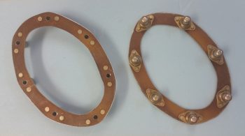
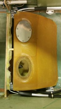
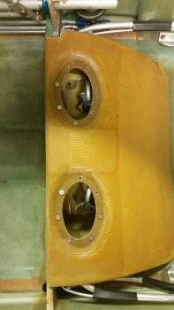
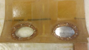
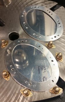
As the sump access ports’ floxed nutplate rings are still curing on the sump top, I figured it was time to get some other tasks completed in and around the GIB area.  I started off in the sump itself by drilling a 1/4″ hole into the bed of micro in the left sump tank to mount a “roll-it-yourself” 4-40 countersunk stainless steel screw as a clickbond.  This 4-40 screw post doesn’t have to be super strong and in many ways will serve as a guide to ensure proper Holley Hydramat positioning in the sump tank… if there actually is such a thing! I say this because with the hard mounted tubing, I don’t see the Hydramat straying off anywhere other than where it is supposed to be.  But again, a 4-40 screw post will serve as a nice guide during the initial install and subsequent replacement of the Hydramats.

I then set the 4-40 countersunk stainless steel screw in place.  It looked like a nice fit!

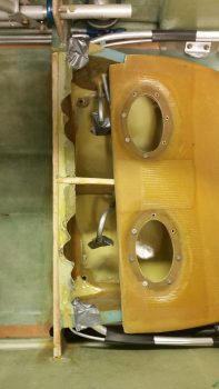
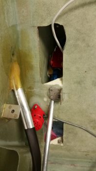
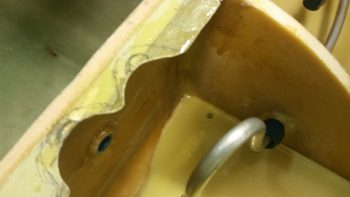
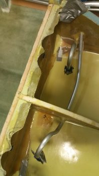
On the right side I couldn’t place the screw post (aka “clickbond”) near the center sump wall since the fuel line tubing going to the left sump is right over where it would need to go. I thought a few minutes about not putting in a screw post on the right side, but then figured if I put it near the drain valve, I doubt seriously if it’s going to block any water draining into that area.

However, since I wasn’t drilling down into the micro-contoured floor, the drain corner didn’t provide the depth I had counted on for the 3/4″ long screw. Standing on the bottom tank floor alone, it was just too tall.  I punted and used a regular 1/2″ 4-40 stainless steel screw, but covered it with an upside down Tinnerman washer to help stabilize it once it was awash with wet flox and subsequently cured –along with a couple plies of BID over top of it.

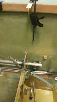
To get the normal screw to stand upright in space I simple taped it to a line, then clamped the line to a popsicle stick hanging off the top of the longeron like a diving board.  I then 5-min glue the bottom of the screw, slightly adjusted the line where I wanted the screw and Voila! … the screw ended up exactly where I wanted it!

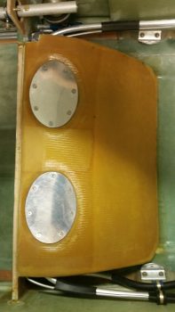
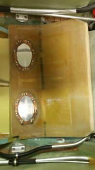
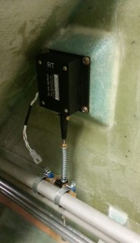
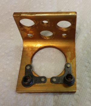
I then floxed in the 2 Holley Hydramat 4-40 corner screw posts, covered each one with some wet BID, and then peel plied them.

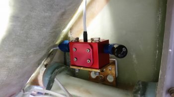
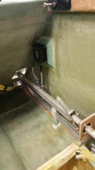
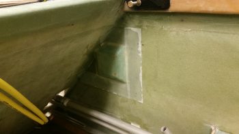
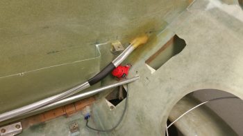
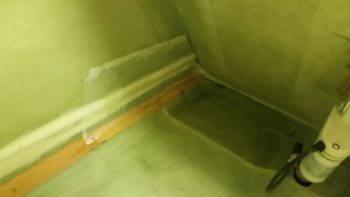
When I 5-min glued the 4-40 Hydramat screw post in the right sump tank, I also 5-min glued the remaining center area –top & bottom– of the piece of German “PVC” pipe that I’m using as my antenna channel cover.

After the 5-min glue cured, I then got to work mixing up some thick micro, slathered it on each side of the channel cover, and then laid up 1 ply of BID over top of that. Of course I peel plied it after I was done with the layup.

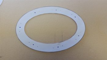
I then decided to take on one of the more challenging tasks on my list: the ram air inlet and expansion chamber for the oil heat system and fresh air intake.  This ram air inlet will also serve to pressurize the cabin more to help offset the negative characteristic of Long-EZs to suck all the bad stuff (cold, rain, small reptiles, etc.) from the outside . . . as per Nick Ugolini who has compelling evidence that his findings work!

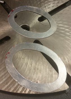
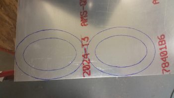
I made a bad assumption in thinking that the urethane foam I have on hand was 2.5″ thick, when in fact it is only 2″ thick.  I had already confirmed with Nick that instead of a 3″ round diameter expansion chamber, that I would be making mine more oblong, or oval, shaped to save some room in the RHS baggage area.  I had planned on making it 3.6″ high x 2.4″ wide.  Well, I ended making the expansion chamber just a hair longer since that was the only dimension I could control with this foam, to still come up with approximately the same volume as I would have before.

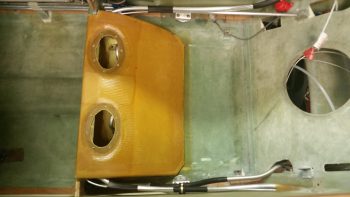
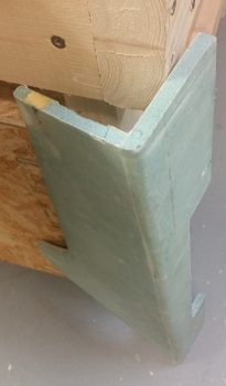
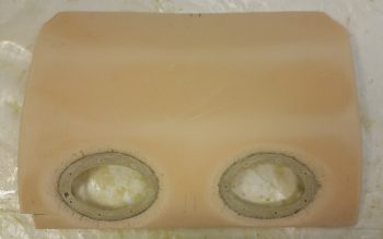
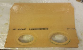
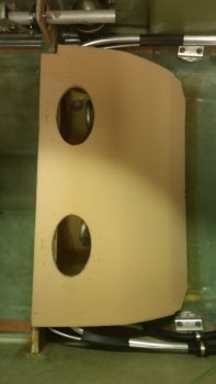
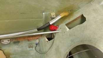
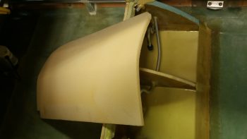
I then shaped the curved inlet and expansion chamber out of the urethane foam.

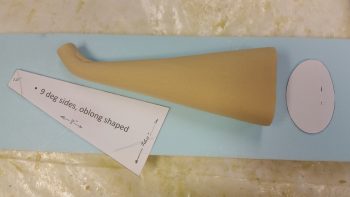
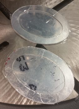
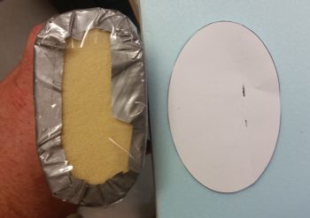
After finalizing its shape, I then covered it with duct tape first, then with clear packing tape.

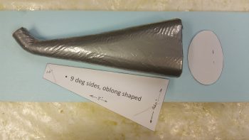
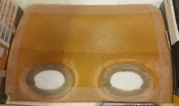
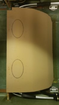
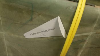
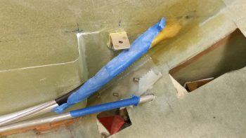
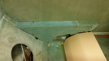
Here’s a general look at how it stacks up with my planned shape.

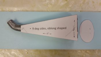
As you can see, the cross section turned out to be a bit more square than I had originally planned (Hmmm, I wonder if Burt ever had this thought cross his mind about the fuselage he designed . . . ha!).  Again, to make up for some of the 0.4″ in width that I lost due to the urethane foam block width.

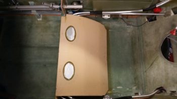
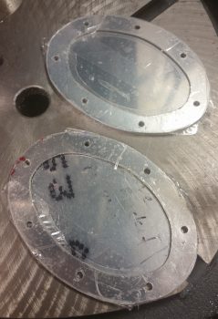
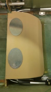
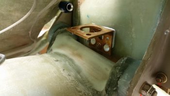
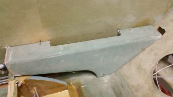
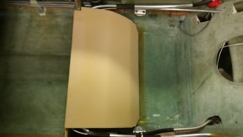
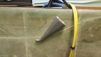
I then very quickly mocked it up on the sidewall to see how it looked.

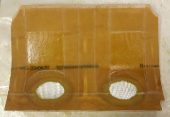
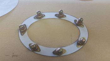
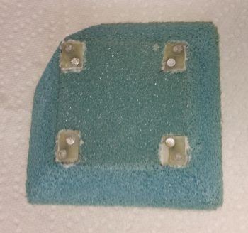
I then also quickly made up a glassing spit for the ram air inlet & expansion chamber.

Here’s a better shot of the glassing spit.  If you’re thinking that I got really fancy with my upright (I know you’re not!), it might look familiar: it’s one of the sump test ribs that I cut out of OSB plywood.

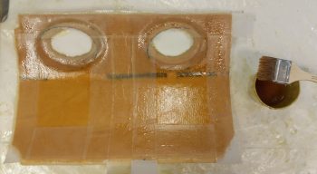
I have to admit I failed in my layup goal here.  Except for a reinforcement ply of BID at the front and the back for interface strength with other upcoming duct pieces, I was going to use spare UNI for the entire layup since I have a ton of it laying around.

Ugh!

I couldn’t do it…. what a royal pain that stuff is trying to go around any smallish curves.  I did got a couple of plies on, but the small front 1″ opening was going all wonky on me and after fighting off the attack of the killer strings for over half an hour, I finally threw up my hands and magically one of them landed on a piece of BID . . . A SIGN!  ha!

Ah, laying up a ply of BID after fighting UNI is like eating real butter!  Smooth & silky! Anyway, I added a final ply of BID, peel plied the ends and the seam down the side and called it a night.

Mission complete.  Tomorrow I won’t get much done.  Out of town visitor flying through to fly out, then a birthday party after that . . . busy, busy!  I will continue to work on both the sump and the GIB area stuff for a few days before heading north, or forward, to the pilot’s seat area.


Chapter 21 – Fuel sump top GLASSED!

For clarification, the glassing of the fuel sump top is final, but I have yet to flox/glass it in place on the sump tanks assembly . . .

So, as I mentioned last night, I let this layup cure to around 80% and then placed it on the sump assembly in the fuselage, where I then weighed down the edges (again) and cooked it to perfection with heat lamps!  Before I actually put it back onto the sump assembly though, I did pull the peel ply (while it was EZ!) and knife trimmed all the edges.  I also removed the peel ply intersection ridges and drilled out the 7 screw holes on each access hole perimeter flange.

The usual temp that the backseat area gets to in this configuration is around 120° F, so I figured I would let this cook for about 4 hours.  I went upstairs and spent a good hour migrating my blog posts over into the build log pages, and then went for a quest for some 8-32 screws –which I bought at my local village hardware store– and some cork-rubber gasket material, which I picked up at a local auto parts store.

I chose cork-rubber gasket material since the sump access port perimeter surfaces that I’ll be using the gasket on is not perfectly even nor totally smooth.  Cork is the most forgiving of the affordable gasket materials, and from all accounts, once married up with the venerable Permatex #2, it’s virtually leak proof.

Upon returning home I got everything prepped and ready to start back in on the sump build, while the sump top itself had post-cured for right at 5 hours.  Again, I had pulled all the peel ply and knife trimmed it before I cooked it, so this time around I was just checking the layup over for quality (there were some minor delams where I folded the glass around the edges of the foam which I simply cut away) and giving the edges a nice final sanding with the hardboard [FYI/FYA – Pulling peel ply after a part has been post cured is NOT fun!].

One of my first tasks out of the gate today was I needed to trim down the outside edges of each sump access hole nutplate ring.  Since the glass on the bottom side around each hole went just a tad wonky on me, I needed to make the footprint for each nutplate ring as narrow as possible.  I trimmed up each ring with the Dremel tool and a cutoff disk, and then finished the edges with a couple rounds of filing.

I then started an iterative process of trimming away half circles on the front sump wall flange to allow clearance for the nutplate rings once mounted in place on the underside of the sump top.

I was also a bit concerned with the sheer wonkiness of the right access hole glass, so I checked it out first with the top cover plate in place to ensure it didn’t need any special attention. Actually, the only special attention I had to give anything was that I had to curve the top cover plates a bit for a better mounting contour.  Now, even though these cover plates are ONLY 1/16″ 2024 aluminum, they are NOT EZ to bend!

Well, I got the top plates bent well enough, and then test mounted them both into place with a full compliment of 8-32 screws into their respective nutplate rings on the opposite/interior side of the sump top.

After a half dozen rounds of trimming the sump front wall mounting flange, I was able to slide the sump top into its final mounting position with clearance for both access holes’ internal nutplate rings.

With the sump top ready to be mounted, I decided I wanted to try it out to ensure there just wasn’t any unforeseen problems I was missing.  Plus, I was curious how well it would work.  The picture below may seem like some crazy guy taking a really weird pic, but I wanted to show that both GIB left & right armrests were installed, plus the sump top was in place.  This is the first time that I’ve sat in my plane when it actually felt like a real seat in it!

How does the thigh support feel?  AWESOME!  I haven’t sat in too many Long-EZs, but whether or not any builder is using a thigh support sump, they should definitely go for the thigh support.  It felt so good I almost fell asleep just sitting there pondering my build!

The next step was to get the access holes’ nutplate rings floxed to the hole flanges on the internal side of the sump top.  I whipped up some flox using E-Z Poxy and very carefully floxed the nutplate rings in place.  I had planned on using the access hole cover plates to help ensure the angle of the screws were correct, but right about when I was getting ready to put the screws into the flange on the left side, I heard a huge crash upstairs.  Something had definitely fallen.  Well, my fingers were all covered with flox so I quickly put the screws in and tightened down the nutplate ring, removing all the excess flox that was oozing out as I tightened the screws.

Before I did the right side, I went upstairs to investigate the potential calamity . . . well, apparently Jack Wilhelmson’s canopy latch kit didn’t like my tall surround sound speaker and took it out.  I uprighted the speaker and separated the two, and then got back down stairs to finish floxing on the right access cover nutplate ring.  It was then that I noticed in the distraction of the loud bang of something falling down upstairs, that I had forgotten to place the access hole cover in place on the left side.  Oh well, I’ll mount it when I do the screw swap outs to ensure the screws don’t get floxed into place.

I plan on letting the floxed nutplate rings cure for 2, if not 3 days, to ensure the flox really holds these guys in place.

Since I knew I would mixing up flox, before I started the process of floxing on the access holes’ nutplate rings I marked & dug out the foam on the front edge of the GIB right armrest to create a mounting tab hardpoint.  Thus, after floxing the nutplate rings into place, I added some micro to the leftover flox for a good mix of flocro and then filled in the hardpoint divot on the GIB right armrest.  When I get a chance over the next few days, I’ll flox the GIB right armrest mounting tab into place onto the aft side of CS118 mini bulkhead.

Tomorrow I’ll be working on other tasks besides the fuel sump as I let the floxed nutplate rings cure fully.  I do need to prep the internal floor of each sump tank with a 4-40 click bond (most likely a roll-yourself one) to ensure the Holley Hydramat stays in place on each side.  I also need to clean out the fuel lines before the sump top gets glassed into place.


Chapter 21 – Sump top glassed

I started out today by spending over 6 hours updating various parts of this website.  I cleaned up the electrical system main page by adding subpages, and I added a subpage to the Chapter 21 page for the GIB thigh support fuel sumps.

I then finally made it into the shop very late in the afternoon to start in on the fuel sump top exterior.  My goal was to get the sump top exterior glassed today, which I was able to do.

I started by spending a couple of hours working on the sump tanks access ports’ holes. My theory on the glass pulling away from the foam was right for the most part, which distorted the shape I had created for the way the metal nutplate rings would lay in the depression ring around the underside of each hole.  Being an ‘ol Bomb Disposal Tech, I simply improvised, adapted and overcame by taking the topside hole perimeters down to glass.  The glass ring around each hole isn’t optimum for what I want to do, but it’s definitely workable. Most notably, what it will probably mean is that each top cover plate will have to be curved slightly to match the (now) more curved shape of the just glassed rings.

Once I removed the foam around each access hole and took the hole perimeter down to glass, I then found the optimum alignment between top and bottom plates, then drilled the 7 screw mounting holes in the ring around each access hole.

I then sanded a transition in the foam around each hole to the surrounding foam surface, and also hit the raised “square” edge lines that where an unwanted byproduct of curving the foam with heat and using a weighted board to make the curve.  I should note that I had already sanded both the right and left sides of the top to get the edges aligned with their respective sump walls, exterior/outboard sides. Once I cleaned up the top foam surface of the sump top, I then vacuumed it in prep for glass.

As for the glass schedule for the exterior of the fuel sump top, it was slightly different than how the rest of the sump was glassed.

Obviously I want this sump to be more impact resistant than if I had just used BID alone. So, for both strength and impact resistance, and to add another ply for fuel resistance, I made the first ply on the interior sump walls Kevlar.  However, since the top will see its fair share of things dropped on it, getting stepped on, pointy things trying to pierce it, etc. I went ahead and put the Kevlar on the exterior side, covered by a ply of BID.  I did add another 6″ wide strip of BID across the front of the top cover for strength, especially for the glass-to-glass access holes’ rings.  Then, immediately around each sump tank access hole, I added another ply of BID.

Finally, before I laid up the final top ply of BID, I added a small strip of Kevlar in the center in between the access holes (where the bridge of the “nose” is on my very humanoid looking layup . . . can you see the eyes?!) which is essentially where the GIB will step every time when ingressing & egressing the airplane.

I’ll let this layup cure to around 75-80% (i.e. in the morning) before placing it on the sump assembly in the fuselage, where it will get weighed down on the edges (again) and cooked to perfection with heat lamps!


Chapter 21 – Interior layup cleanup

Today I started off by shutting off & pulling the heat lamps from the sump top interior layup post cure.  I then slowly and carefully pulled all the weights off the top.  I then carefully worked the top off of the lower sump walls and flipped it over to inspect it.  All the glass was in good shape.

The only minor issue I had –unintended consequences– was that the BID that was securely in place in the “pockets” around each access hole separated off the foam surface slightly in a few areas.  I’m thinking that in the depressions for each access hole, they probably pulled out just a hair in those few areas because I pulled the glass slightly taunt around the holes by weighing down the entire sump top foam plate with weights.  No major worries.  A bit more work and assessment, but still very workable.

I then proceeded the quite understated process of pulling peel ply, cleaning up the peel ply edges and trimming the glass overhanging the perimeter edges with the Fein saw.  This entire endeavor took nearly an hour by itself!  I left the glass in the access holes so that when I’m sanding and shaping the topside hole perimeters, the glass will serve as a “catch” to keep all the foam bits & dust from getting into the sump tanks.

After cleaning up the layup and trimming the overhanging edge glass, I then stuck the sump top back in place.  I’m very pleased with the fit and all indications convey that it mates securely at every contact point along the top of each sump wall.

There is a slight unevenness to the top since the weight on the right side pushed the aft side of the right access hole down just a bit more than the left, maybe 1/8″.  But with a bit of judicious sanding and when the top ply of Kevlar and BID are glassed into place, I think it will be barely noticeable, if at all.  It certainly doesn’t have an operational impact on the sump.

Tomorrow I’ll continue my quest to get the sump top glassed into place, with the access ports’ nutplate rings floxed into place and the screw holes drilled out.


Chapter 21 – Glassing sump top

Today I started out by cleaning up the edges of all the metal pieces I cut yesterday.  After removing the plastic covering on each side of all the metal pieces, I realized that the plastic itself was hiding a bit of a sharp ridge all around the edges of the cut aluminum, so I took a fine file and smoothed the edges down.

I then drilled out the rivet holes for each nutplate assembly on the sump tank access ports’ internal rings.  After I drilled the pair of rivet holes for each nutplate, I then drilled a countersink for each hole to allow the countersunk rivets to be installed flush.

I then Alodined the sump tank access ports’ internal rings and hung them up to dry.

With the sump access ports’ internal rings Alodined & drying, I then cut all the BID required for glassing the underside of the sump top.  I prepped the foam surface by applying wet micro-slurry to it.

I then glassed up 1 ply of BID across the front edge that also covered the sump access port holes.  Then, each hole got a ply of BID that just covered the hole, making 2 plies of BID around the edge of each hole.  After that, I laid up a ply of BID that covered the entire bottom side of the sump top, obviously making 3 plies of BID around the edge of the access holes.

I used 3 plies around the holes because I was originally planning on going glass-to-glass between the top and underside of the sump top around the lip of each access hole.  I decided that I most likely wouldn’t go in that direction now, but I wanted to keep that option open and I had already cut the BID for this layup, so I went ahead and added the smaller ply around each hole . . . which is the only difference between going the glass-to-glass route or not.

I then peel plied all the edges, around each access hole, and a fairly wide strip down the center from front to back.

As the layup on the sump top foam piece underside cured, I then riveted 7 covered nutplates to each sump tank access port internal ring.

I then left the layup to cure for a few hours and went to dinner with a buddy of mine.

Since E-Z Poxy with EZ84 hardener takes around 8 hours to cure, I had already planned on letting it cure about half-way so that it was nice and tacky, almost greening, but definitely setting up before putting it in place on the sump tank in what will be very close to its installed position.  Of course, before I set the glassed & curing sump top in place I applied clear packing tape to the tops of all the vertical sump components, and the aft dam area.

I then piled a bunch of weights on top of the glassed sump foam top to press it firmly in place along all the contact points.

After a few minor adjustments of the weights, I then mounted the 2 heat lamps and fired them up.  I then covered the area with an insulated foam panel.

Tomorrow I plan on glassing the top side of the sump top, but I won’t glass it in place onto the sump since I need to flox the sump tank access ports’ internal rings in place before the top goes on for good.


Chapter 21 – Sump access ports

Today I started off by sanding the internal foam edges around each sump tank access port hole.  Since the sump top is angled and slopes down almost immediately from the front sump wall, I want to get the sump access port covers configured so that they are as level & parallel with the aircraft’s waterline (0°) as possible.  To do this means that the foam around each opening is actually shaped so that on the top side (remember, I was working on the bottom side of the sump top foam piece) the foam is low on the forward side of each opening and as high as possible in the back.

To prep the inside foam for glass, I simply reversed what will be seen on the top with the front side getting a slight depression –in preparation for the 0.040″ thick nutplate ring– and the aft side getting a much deeper depression, when inverted, meaning that it will place the nutplate ring nose side low and tail side high.  Exactly what needs to happen to get the access port cover as level as possible.  I spent well over 1.5 hours sanding & shaping the foam around each opening (and my aching shoulder can confirm that it was that long!).

Since I’m meeting friends early this evening for dinner, I wanted to ensure I got all the noisy stuff for today’s build out of the way as early as possible.  I loaded up a new bit on my Saber saw and cut out the 2 nutplate rings out of 0.040″ 2024 aluminum.  I then spent a good 5-10 minutes on each one cleaning up the inner & outer edges with a file.  Of course cutting them with a Saber saw meant they didn’t come out perfect, but they certainly meet my requirements and will do the job fine.

I then matched each ring up with a port cover plate as best they aligned and then taped them together with clear packing tape.

I then used my paper template and marked the 7 screw holes on each ring.  I then drilled out the screw holes to attain a spot-on alignment between each nutplate ring and cover. To ensure I didn’t get the cover plates or sides mixed up, I used a scribe to place a small “A” on one set, both cover and ring, and a “B” on the other.

I then pulled the protective film off all the aluminum, set up a screw to show the alignment between cover & ring, and then set a number of the covered nutplates in their positions to provide a general idea of how these pieces work & go together.

Tomorrow I’ll Alodine these aluminum pieces and glass the internal side of the sump top cover.  I’ll then rivet all the nutplates to the sump access port cover rings.  Since E-Z Poxy needs a good cure, I won’t really get to glassing the sump top in place until either Sunday night or Monday.


Chapter 21 – Sump tank access ports

Today I started off with a long discussion on the phone with Nick Ugolini about the oil heat system.  I had a bunch of burning questions and Nick was of course gracious enough to answer all my questions.

After spending over a good hour on the phone, I then documented all that Nick and I had discussed.

I then went downstairs and started working on the fuel sump access ports.  I had determined last night the nutplate attach ring that goes on the interior side of the tank was just a bit too wide, so I reduced the width down to 5/8″ from 3/4″.  I then spent some time spacing out the 7 nutplates equidistant on the ring and marked them up.

From the rivet holes on each nutplate I then determined the actual center for each one & marked it.

Using my paper template, I then transferred each sump tank’s access hole onto the sump top piece of foam.  I also marked the outer edge of the ring (and each sump access port cover) with a dashed line.

I then cut out each sump tank’s access port hole and set the foam top back over the sump tanks.  So far, I’m very happy with the configuration and spacing of these access holes.

I then cut out the access port covers out of 1/16″ (0.063″) 2024 aluminum.

Since it got too late to be cutting metal in the shop this evening, I just went ahead and marked up the sump access ports nutplate rings to be cut out tomorrow.  I’ll be using 0.040″ 2024 aluminum for the nutplate rings.

After my discussion with Nick, I also tweaked my air intake scoop expansion chamber and played around with some potential configurations and locations on the fuselage.

Tomorrow I’m going to attempt to get the nutplate rings cut out, the screw holes drilled and all the access ports aluminum Alodined.  I’ll then rivet the nutplates to the nutplate ring.  In addition, I’d like to get the inside of sump top glassed with 1 ply of BID after I shape the interior foam around the access ports.


Chapter 17/21/22 – Mounting stuff!

This morning I spent a couple of hours planning and diagramming out my oil heat system. I’ve been collaborating with Dave B. on it, but still need to query Nick Ugolini on some of the specifics of the oil heat system he developed.

Next up was simply mounting some stuff.  I had some errands to run today, and then dinner with friends tonight, so before I headed out I wanted to get some stuff mounted to ensure my efforts in installing brackets & mounting pads were successful.

First up was the FT-60 “Red Cube” fuel flow sensor.  I used a couple of thick washers on the AN4-17A bolts and put it in place.  The spacing was tight, but I got the bolts in nice and snug with the unit correctly aligned with the fuel line coming aft from the fuel boost pump. Thus, the fuel flow sensor install is marked off the list as complete!

I also double checked the clickbond spacing for mounting the fuel vapor sensor element, and they were spot on.  In the pic below you can also see the new GIB right armrest mounting tab just above the engine fuel feed line.  Lastly, you can see the mounted fuel flow sensor peaking out from behind the back seat.

For the Roll Trim servo mounting I carefully drilled out the glass covering the 4 corner #6 screw nutplates.  I then pulled out the plastic wrap that I had stuffed into each nutplate to protect it from epoxy.  Once all the mounting holes were clear, I then mounted the RAC Roll Trim servo in place.  After a slight adjustment upwards of the spring assembly, I then set it in place and loosely attached the 2 hose clamps that when eventually installed for good will allow the servo assembly to rotate the control tube (spring arm up or down), which translates into aileron left or right movement for trim.

Here’s a closer shot of the mounted roll trim assembly.

I also spent well over an hour mocking up the fuel sump tanks’ access ports, determining both size and shape and testing them out.  I finalized an oval shape with an access hole of 2.5″ high x 4″ wide.  These access ports will allow me to initially install the Holley Hydramats when need be, inspect them during annual condition inspections or whenever necessary, and swap out the mats in 5-10 years as required.  I also determined the width of each interior 0.040″ thick mounting ring to be 5/8″ (0.625″).  These are the rings to which the covered nutplates will get attached.

I then made up templates of the fuel sump access port mounting rings and covers in PowerPoint and printed them out.  After some judicious sanding on the sump top, I then measured out the access port locations and marked up the sump top.

Tomorrow I plan on making the fuel sump top my sole project to get the sump access ports cut out & locations shaped.  I then plan on getting at least the inside of the fuel sump top glassed with 1 ply of BID.


Chapter 17/21/24 – Chapter 17 complete!

Well, I have to admit that when I started off this morning by using 5-min glue to mount the fuel vapor sensor module’s clickbonds in place, I realized I have may have been a bit too thick with the praise for MGS over E-Z Poxy when it comes to mounting clickbonds, since I do quite often use 5-min glue to initially hold them in place.  However, I will still state that I have not had an issue with either 5-min glue or MGS when it comes to clickbonds.

Moving on.  I prepped the bottom of the fuel vapor sensor module with clear packing tape, then put some dabs of 5-min glue on each prepped clickbond and set it in place.

A bit later I laid up 2 plies of BID over these clickbonds and then peel plied the layup.

Today I also finished drilling & countersinking the rivet holes for the nutplates that will eventually get mounted onto the armrest (etc.) mounting brackets.

Here’s a shot of the drilled and countersunk rivet holes in the mounting brackets.

I then Alodined the armrest mounting brackets and the FT-60 Red Cube fuel flow sensor mounting bracket.

I then riveted the 90 deg. corner -4 nutplates in place on the FT-60 Red Cube fuel flow sensor mounting bracket.

Here’s a shot of the bottom side of the bracket (my Alodine is a bit old, and unlike a fine wine it doesn’t get better with age… maybe that explains some of the splotchiness on my bracket… not sure…)

And here is the  FT-60 Red Cube fuel flow sensor mounting bracket after I floxed ‘er up and bolted ‘er in!

I then got to work on the Roll Trim mounting pad.  I had ordered K1000-06 nutplates for the 6-32 screws that will be used to mount the RAC servo to the fuselage sidewall.  Well, I had a “Doh!” moment when I realized that since the RAC servo has corner mounting holes, I should have ordered 90° corner nutplates.  Oh well, since the Roll Servo is fairly light and in normal ops not an overly used device, I made a command decision that one rivet tab would do to hold each nutplate in place on its respective G10 Garolate nutplate base.

[Note: Normally this servo would get mounted straight to the sidewall, but since I had to kick in my control tubes about 3/4″ inboard to allow for the CG controls, I am simply “extending” the fuselage sidewall inboard 3/4″ with this foam base]

Once I got all the nutplates riveted to their 1/16″ G10 base, I mounted them to the RAC servo and figured out their exact location in the foam.  I then notched the foam at each corner and embedded each nutplate assembly.

I then taped up the bottom of the RAC servo to use it as a guide, and then mounted the nutplate assemblies back onto the servo.  I then micro’d up the bottom of each nutplate assembly and the corner notches in the foam.  I set the nutplates (with servo) in place, and once satisfied that they were all in the right position, weighed down the servo to press the nutplates into their respective notched corners (I failed to get a pic prior to this of having shaped the edges of the foam to allow for glass transition to the fuselage sidewall).

Later, after it all cured, I filled each nutplate with plastic/saran wrap to keep the micro out of the nutplate threads.

Later still, I prepped the foam roll trim servo base with micro and micro’d it to the right fuselage sidewall just aft of the pilot’s seat.  I then laid up 3 plies of BID over the foam base and then peel plied the edges with 2″ peel ply tapes.  I double checked the elevation a few times using the RAC servo with the spring push/pull assembly attached.  With only a few minor tasks left, like drilling the screw holes and pulling the protective plastic wrap out, I’m calling Chapter 17 – Pitch & Roll Trim Systems, complete!

Tonight I floxed in 3 mounting tabs that were screwed to the GIB left armrest.  These are 3 of 4 tabs that are located primarily on the aft side of the armrest.  I’m planning on building a small framed mounting bracket that will be used to also house the GIB headset jacks and PTT button on the front side of the left armrest, which will have a nutplate attached to it and be the 4th mounting tab.

In addition to the left side armrest, I also added another mounting bracket to the GIB right armrest by floxing in place a tab on the aft side of the armrest where it meets up with the seat back.

Tomorrow I really do plan on working on the fuel sump top, but will be going out to eat with some friends so it won’t be a completely full work day.


Chapter 21/24 – Bit here, bit there

I started out today wanting to get the FT-60 Red Cube fuel flow sensor mounting bracket finished so that I could Alodine it with the armrest mounting brackets that I planned to prep as well.  Well, I went as far as I could before having to get on the road to head up towards the Dulles area to help out a friend.

I did get the FT-60 bracket configured with the mounting bolts drilled and the corner nutplates’ rivet holes drilled out as well.

I countersunk the rivet holes in prep for using flush rivets.

Thankfully, after the click bond disbonding issue, I was able to get the bolt holes aligned correctly, since the Red Cub sits on its bracket at a slight angle left-right to align properly with the fuel feed tube.  I added the nutplates in the pic so you can get a sense of how it all goes together.

Also, after pondering it for the last day or two I decided that with all the fuel lines, fittings & components in the back seat area –and the entire cockpit actually– that the fuel vapor sensor that I bought while I was in Qatar was going back into the lineup.  I just think that it’s the prudent thing to do to have the earliest possible warning of any fuel leak, at the vapor level before it gets any bigger/worse.  I decided on an out-of-the-way spot for the sensor element and will mount it there (it’s just mocked up here) with 2 click bonds using?! . . . yep, MGS!

I know I stated in my video that the sump top was the next item to be worked, and I have been (slowly) working on curving the top cover of the fuel sump by heating it up.  I have never undertaken the curving of foam by heating it up, as the plans references a few times for curved foam parts.  The feedback that I’ve seen on this method has not been good, and most people generally cut relief grooves and curve the foam that way.  I wanted to try it simply out of curiosity.  It does work, but there is some inherent problematic issues in heating it up to curve it.

First, I started off trying to simply use the fuel sump as the form and set the lid foam on top of it.  I then weighed it down and heated it up in place there.  I thought there might be some issue with some spring back after I removed the foam once it cooled, and I was right.  With that knowledge in hand, as well as some nice scrapes on my fuselage floor from heavy weights leaping off the tricky curved sump surface, I decided to shape the foam off of the actual sump.

Next, to get an even curve, I used a 1×4 board base as I weighed it down with weights with the top set upside down against a 4×4.  Well, the end result was angled curves with “corners” somewhat like you’d get with a hex shape.

No big deal, but it is something I’ll have to contend with.  I’ll keep working the top sump cover as I finish up these smaller sideline tasks for the time being.

Finally, I spent a good couple of hours working on my last batch (hopefully!) of mounting tabs for the GIB left armrest, as well as backfilling some inventory that I stole from the front & aft right side armrests.  Over the next day or so I do intend on getting the GIB left armrest mounted, as well as getting 2-3 more tabs mounted on the right side as well.  I did run out of time finishing these up to get them Alodined before installing them, so I will work to get this batch knocked out tomorrow.

After a not so productive weekend as far as the airplane build is concerned, I’m hoping for a very productive week!