Chapter 22/24 – GIB area tidbits

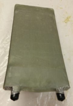
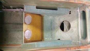
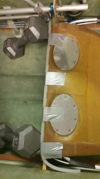
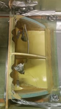
Today I started off by prepping the corners of my recent heat exchanger BID cover for glass.  I had actually glassed on a couple plies of BID during the initial glassing of the heat exchanger cover, but with so much finagling of the glass to get it to lay down right, the corner plies were mangled beyond use so I just pulled off the blobs of BID and chucked ’em.

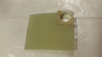
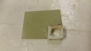
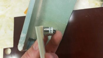
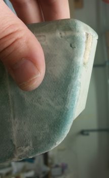
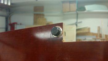
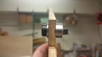
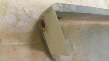
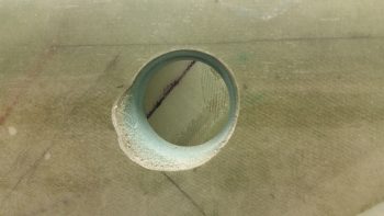
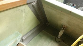
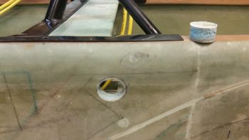
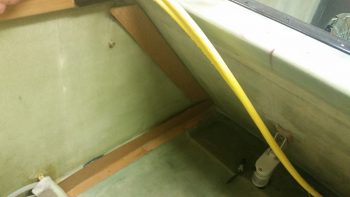
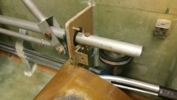
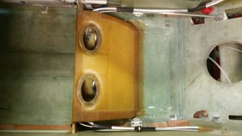
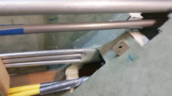
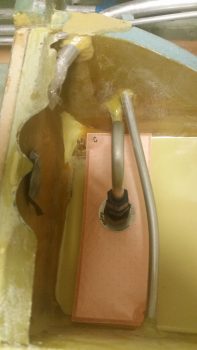
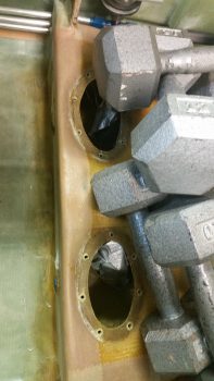
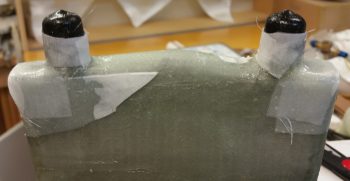
Now it’s time to remedy the exposed corners immediately adjacent to the AN fittings (black caps) on the oil inlet and outlet tubes of the heat exchanger.  I knifed some dead glass away and sanded the corner areas in prep for the 2-ply BID layups.

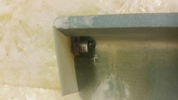
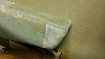
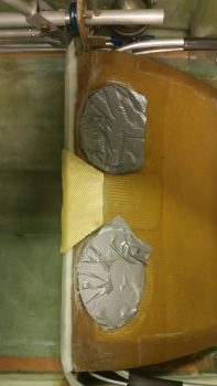
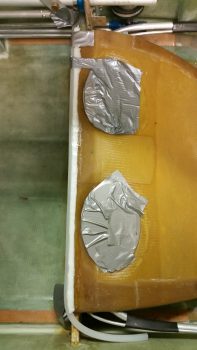
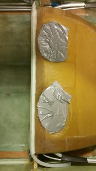
I then laid up 2 plies of BID on each corner and peel plied the layups.

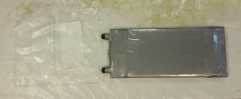
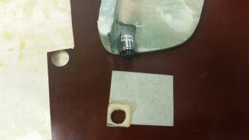
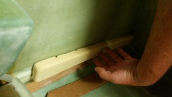
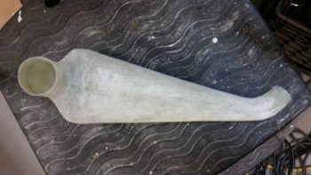
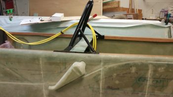
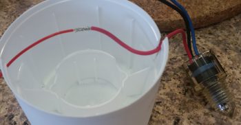
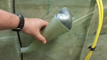
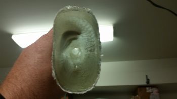
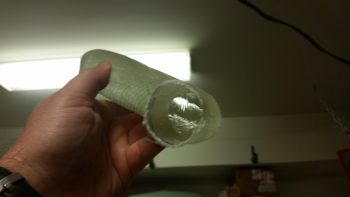
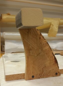
I then got to work on the left GIB armrest forward composite mounting bracket that will also house the GIB PTT button & GIB headset jacks on the front face of it (which will get attached to this bracket frame later).  I used a 2″ thick urethane foam block for the form and cut the block 3″ long.

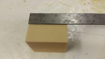
I then sanded the foam block form into shape, radiused the corner edges for glass and taped it up with duct tape.

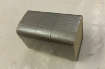
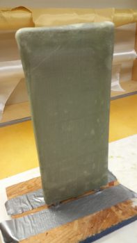
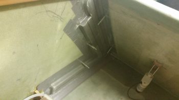
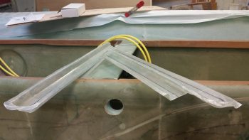
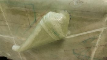
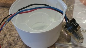
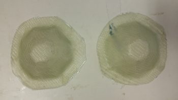
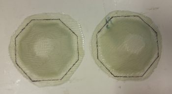
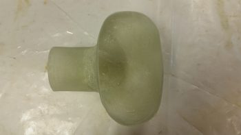
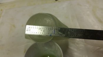
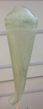
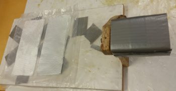
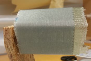
I then cut out 3 strips of 3″ x 8″ BID and 2 strips of UNI the same dimensions for a total of 5 plies of glass.  I then put the glass into plastic for a prepreg setup.  I also mounted the  left GIB armrest forward mounting bracket form onto a vertical stand to make laying up the glass onto it much easier.

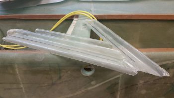
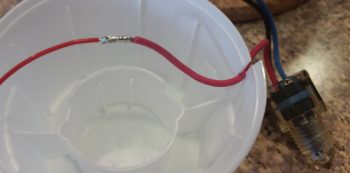
Here’s another shot of the left GIB armrest forward mounting bracket form attached to its vertical stand.

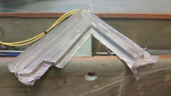
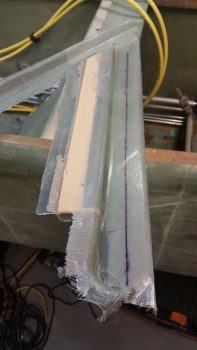
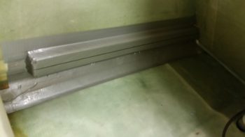
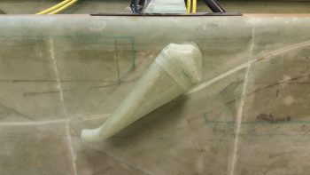
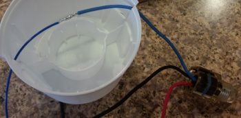
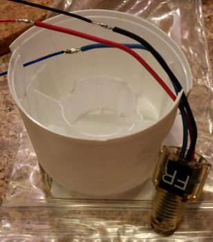
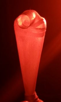
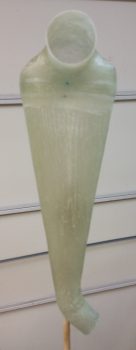
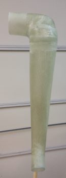
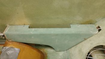
I then laid up the 2 sets of prepregged glass so that the layup schedule was a simple BID-UNI-BID-UNI-BID pattern with the UNI plies at a 30° bias, with each UNI ply in the opposite direction.  I then of course peel plied the layup.

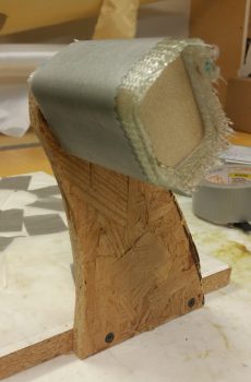
Yet another shot of the 5-ply glass layup for the left GIB armrest forward mounting bracket.

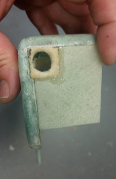
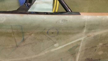
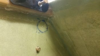
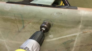
With the same epoxy I also whipped up some micro to pour into a hardpoint divot that I had created at the left GIB armrest forward mounting point.

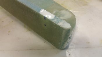
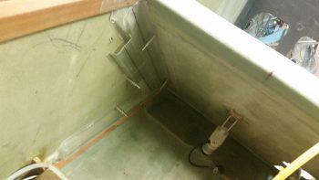
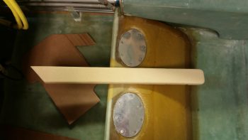
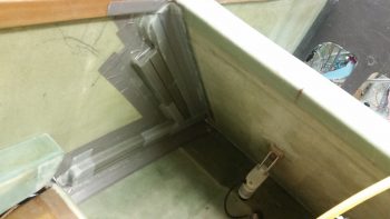
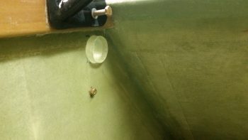
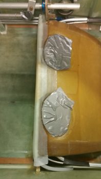
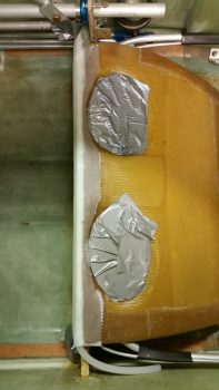
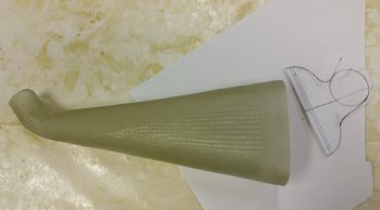
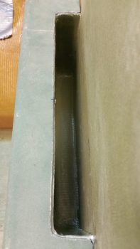
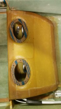
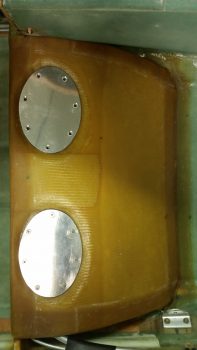
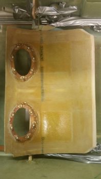
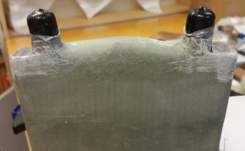
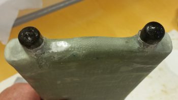
By this time, the layups on the two corners of the heat exchanger had cured.  I pulled the peel ply and cleaned up the layups while they were still in that nice “green” stage.

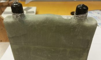
Here’s another shot of the layups on the two corners near the AN fittings of the heat exchanger.

Tomorrow I’ll continue to work on both the heat exchanger and heating/air ducts while also working on the left GIB armrest forward composite mounting bracket.


Chapter 22/24 – PTT & Heat Exchanger

Late Friday I laid up 1 ply of BID across the front face plate of the GIB left armrest.  I pulled the BID down through the hole in the foam recessed housing for the PTT button.

Well, when I trimmed the glass off on Saturday, unfortunately a good chunk of the foam came with it.  I then needed to repair it of course.  Being in a rush for a social engagement, I quickly wrapped up the PTT button in saran wrap & tape, and then set it in what remained of the hole and weighed it down.  I then whipped up some flocro and –using the taped-up PTT button as a form– rebuilt the recessed housing “frame” around the PTT button.

Here’s a shot of the left GIB armrest’s front face plate, with the repaired PTT button foam recessed housing.

I haven’t sanded down the repaired PTT button foam recessed housing to its final shape yet, but will get to it after the July 4th holiday festivities are over.  Still, here’s the aft side of the left GIB armrest’s face plate.

Today I focused on glassing the heat exchanger.  With help from my lovely assistant (Stacey is visiting from North Carolina and helped with both the prep and the glassing of the heat exchanger… and I have to say, it was great having an extra pair of hands on this somewhat challenging layup!  Thanks Stacey!) I taped on two 1/4″ thick rounded wooden runners on top and bottom (that I cut on the table saw Saturday), made some flat cardboard end caps for the U-shaped tubing on each end to make the whole cover a more even rectangular shape, and then wrapped it all in plastic.  I then taped it all up, first with duct tape, then with clear packing tape.

We then cut out BID to make up a 2-ply prepreg setup for each end.

We then wet out the prepregged BID and laid up the end pieces.  Then over the end pieces, we wrapped and wet out 3 individual plies of BID, one at a time around the entire middle area of the heat exchanger.  The corners did give us a hassle, so on the non-AN fitting end I used a bit of micro in each corner and laid up some “corner cap” pieces of BID.  I left the corners on the AN fitting side alone for now and will glass them during round 2 of enveloping the heat exchanger in glass.  After laying up all the glass, we peel plied it all and let it cure as we went out to meet some other friends for dinner.

Above and below are actually shots of the glassed heat exchanger after I pulled the peel ply.

Tomorrow we’ll be celebrating July 4th, so no building is planned.  I do plan on getting a fair amount knocked out starting back full steam on Thursday.


Chapter 22/24 – PTT & Ducts

I started out today working on the GIB PTT button configuration & construction of a front plate for both the GIB PTT button and GIB headset jacks, all which will reside on the front of the left GIB armrest.  It may be a bit hard to tell, but the greenish blob coming down from the top of the pic below is the front of the left GIB armrest.  Top of armrest is to the left, with the PTT button resting in the notch I created for PTT button clearance.

I positioned the PTT button notch where it is to get the PTT button as far up into the inboard corner of the armrest front face for easier “mashing” of the button any time the GIB is going to use it.  However, to stay clear of the PTT button being inadvertently pressed or an open mike situation, I’m recessing the button so the top of it is just below the face of the armrest front face.  Thus, at the center bottom of the pic is the piece of 1/16″ G10 I cut as the armrest front face cover plate, and in the corner where the PTT button will go, I notched it and shaped a piece of Divinycell foam with a 1/2″ diameter hole for the PTT button to sit in.  I 5-min glued the foam piece in place, then when cured I radiused the perimeter edge of the hole.

All this is sitting on a piece of 1/4″ phenolic which I drilled a 0.609″ (39/64″) hole into for the actual securing of the PTT button as it’s press fitted into this hole with some Silicone RTV to lock in nice & tight.

Since the left armrest front tapers aft at the bottom, I tapered the foam PTT button recess housing so that the PTT button would sit parallel with the top of the armrest for clearance on the internal side of the armrest.  Here you can see the PTT button set in place where it will get mounted.  If you look just forward (left) of the ID label sticker you can see the wider 0.609″ flange that will get press fit mounted into the phenolic.  The phenolic piece will of course get floxed to the aft side of the tapered foam recess housing.

I then tested the fit of the assembled armrest front face piece in the notched corner I created in the armrest.  When finished, this front face piece will be an integral part of the sidewall bracket that remains on the fuselage sidewall when the armrest is removed.

I had to do some very light sanding after I drilled the 0.609″ (39/64″) hole for the PTT button to fit, which it did with a reasonable amount of force. Perfect.

Again, the physical mounting of the GIB PTT button will be in this 1/4″ phenolic block piece that itself will get floxed to the aft side of the foam recess housing that is attached to the front face piece.

I then cut out the phenolic block and trimmed it up.  I then mocked up the PTT button secured in the phenolic block, set in place where it will attach to the foam button recess housing, all with the front armrest face piece set in place.

Another shot of the recessed PTT button in the left GIB armrest front face piece.

I then started back working on the GIB area heat & fresh air ducts that I laid up last night. My first task was to drill some 3/32″ holes into the flanges and install clecos to ensure I would later have the correct duct alignment when remounting the ducts back in place.

I then removed the clecos and fought for a good 30 minutes to get this ductwork assembly off of the interior fuselage sidewall . . . .

. . .  notwithstanding major puncture wounds to my finger and thumb and a fair amount of blood!!!  Literally blood, sweat and tears in building this plane!

I removed the foam & tape for both the main air feed and the horizontal GIB lower air feed, but the air feed that goes back up top for the GIB high air feed I couldn’t remove without a lot of difficulty unless I trimmed the glass flange that will secure the shared duct wall with the main air feed.  This flange is from the main air feed and had I not subsequently glassed the adjoining parallel GIB high air feed duct right next to it, it would have stood on its own as a “normal” duct without being integrated into a 2 channel duct (or 2 separate ducts sharing an internal wall).

Well, I trimmed down all the flanges and was able to remove the foam from the GIB high air feed duct.  I didn’t weigh this ductwork assembly but it is super light, as one could imagine with it being just a couple plies of UNI.

I then clecloed the air ductwork assembly back in place after cleaning up a few spots on the internal fuselage sidewall.

I snapped this shot of the main air feed as seen from the external fuselage side, through the ram air inlet, expansion chamber and transition tube hole.

Starting tomorrow up until mid-week will be light build days, if I get any building done at all, since I have Independence Day celebration activities, out of town visitors and get-togethers, etc.


Chapter 22 – Phase I Air Ducts complete

Remember, the oil heat system is listed in Chapter 22.

Today I started out by actually finishing up my blog that I was too tired to do last night.

I then sat down and went over some info my buddy Dave Berenholtz had sent me on oil heating, reread Nick Ugolini’s write-up in the latest CSA newsletter, and then proceeded to finalize my oil heat and fresh air intake ductwork plan.

I then went out to my shed, pulled out the table saw and ripped some urethane foam in 3/4″ wide pieces.  With the thickness of the foam being 2″ (I didn’t forget this time!), that makes for the perfect form –according to Nick U.– for making homemade fiberglass heat & air ducting.  According to Nick this glass ducting weighs about 25% of the equivalent length of 1.5″ round SCAT duct tubing.

I then cut each foam piece to length and radiused the outer corners.

For the piece running horizontally over the antenna cable channel conduit I had to create a trough along the entire length of the back side of the foam form.

I then taped the urethane foam form in place and marked the centerline.  Marking the centerline is a fairly important thing not to forget since it allows perfect alignment with the CL of the prepregged glass as it’s laid up.

I then cut the main air feed foam form to shape and length to run from the air inlet that I just drilled last night down to the lower corner to intersect the horizontal duct form that I just taped into place.  I then taped the main air feed duct foam form in place as well.

I didn’t get a pic of the last duct piece before I glassed it all, because it actually got mounted after the main air feed duct UNI glass was laid up to provide a dividing wall between the two ducts via the aft wall of the main air feed.

I then glassed the parallel duct aft of the main feed and overlapped the glass onto the main feed top to created two channels with a dividing wall.  The glass at the bottom edge of both of these leaning vertical upright feeds overlapped onto the bottom horizontal duct, so that when I glassed the bottom duct form it simply created one big layup with the 3 ducts all tied together.  In fact, these ducts will be very close to final configuration without much cutting or major work needed for the airflow to get to where it needs to . . . pretty cool, eh?!

Another cool thing about the layups for these ducts is that I did them ALL with leftover “trash” glass by using overlapping plies of UNI to create a 2-ply prepregged setup with each ply of UNI biased at around 30°-45° in opposite directions.

I’m calling this Phase 1 of the ductwork glassing & installation.  Here’s a diagram showing the ducts I glassed tonight:

And here are the remaining phases (a loose guideline of how this install will flow . . . I won’t necessarily be strictly adhering to it):

  • Phase II – Heat exchanger glassing
  • Phase III – Ductwork interface holes drilled and valves built
  • Phase IV – Ductwork installed with heat exchanger and valves in place
  • Phase V – Oil pump installed & oil lines run
  • Phase VI – Pilot seat area ductwork constructed and installed
  • Phase VII – Instrument panel forward ductwork constructed and installed
  • Phase VIII – Valve cables terminated and handles installed

Obviously I didn’t get to the left GIB armrest forward bracket, although I did spend a good 20 min today locating my 39/64″ drill bit to create the PTT button installation hole!  Tomorrow I plan on glassing the left GIB armrest forward bracket and should have it finished no later than Monday.  In addition, I plan on glassing the oil heat exchanger as well in prep for mounting it over (eg inboard) of the Phase I ductwork I did tonight.

Here’s a general idea of how the heat exchanger box will tie into the ductwork that I glassed tonight:

It may a bit difficult to follow in diagram form, but after it’s glassed and installed it should become much clearer on how it all operates.


Chapter 21/22/24 – Ram air duct prep

Today I started off working for a couple of hours updating 5 electrical diagrams:

  •   A.   Switches, Breakers & Panel Lights
  • .99   Grounding Busses
  •   4.   Electrical System Components Map
  • 10.   Fuel System
  • 11.   Cockpit Lighting

I then spent a couple of hours on the left GIB armrest.  First off I DA sanded down the somewhat grotesque layup edges that where created when I added the top and front extension pieces you can see in the pic below.  Unfortunately, being in a rush to make up for some lost time on personal stuff today, I had one fuzzy pic and simply didn’t take any others.  I know: for shame!  The end result is not only did I radius the front edge and glass it with a ply of BID, but I also filled in some holes with micro in a few different areas on the armrest.

Moreover, I cut a square notch on the very top inboard INSIDE corner that will mate up to the GIB PTT button housing that will be incorporated into the sidewall bracket that will also house the GIB headset jacks.  In addition to the top curve, I also glassed the inside surface of the PTT button bracket notch I made with 1 ply of BID.  Of course all the layups got peel plied.  I’ll get a pic of all the interior layups tomorrow.

I then set my sights on getting the ram air inlet, expansion chamber and transition piece installed on the (current) exterior side of the fuselage.  I double checked my dimensions, moved my initial drill point forward and down just a hair, and then drilled it with a small pilot bit.

And Bingo!  Center of mass on the interior marked hole.

I double checked the overall configuration of how the ram air inlet, expansion chamber and transition piece would mount on the exterior sidewall (which will be inside the strake baggage compartment when the plane is finished).  I then loaded up a 1-1/2″ hole saw bit into my drill and literally pulled the trigger!

Here’s the initial 1-1/2″ diameter hole into the fuselage sidewall, obviously just aft of the pilot seat and just under the left longeron.  You can see the drilled out plug sitting atop the longeron.

Here’s a couple of shots of my test fitting the ram air inlet, expansion chamber and transition piece into place.  The transition tube on this component is 1.5″ ID, which means I had to widen the hole out a bit for this piece to fit into place.  Also, I had to radius the outer perimeter of the hole a bit from around the 5 to 10 O’ Clock position for this thing to mount close enough to the sidewall.

I intentionally glassed the 1.5″ ID air transition tube of the ram air inlet, expansion chamber and transition piece a little long so that it would definitely clear the inside surface of the fuselage sidewall.  However, the excess, overhanging tube edge will be cut down so that the transition tube edge is flush with the interior surface of the sidewall, since the air will immediately flow into the heating and fresh air ductwork at this point.

You know me, the peel ply king, and the one time I thought I could get away with not doing it, I ended up needing to sand this sucker down… well, in the end not all of it, but a good portion of it!  I call this picture: The Mummy in Repose …. haha!

Now, I need to research just how far away from the outer skin the intake needs to be mounted, so the ram air inlet, expansion chamber and transition piece floxing-in & glassing is on hold until I finalize these installation specs.  If anyone out there is smart on this, by all means send me a note!  Here it is one last time, mocked up after I sanded it down.

After all the excitement with the ram air inlet, expansion chamber and transition piece, I decided to do something more my speed: heat shrink!  I finally got around to cutting the heat shrink tubing for the left & right sump tanks low fuel level sensor wires and heat shrunk them in place.

In my short term quest to finalize the GIB area components install, tomorrow my main effort will be to get the left GIB armrest forward bracket mold made up so I can glass it up.  Over the next few days I want to get the left GIB armrest bracket completed and have a good amount of the oil heat & fresh air ducting figured out & built.


Chapter 21/22 – Sump glassing done!

Today I started out by cutting a small wedge of Kevlar to place over and around the sump’s front corner edge Nylaflow conduit.  I wanted to make sure that when the GIB steps into & out of the back seat that the Nylaflow conduit doesn’t get damaged.

I then cut the 2nd ply of BID to get laid up over the first ply of sump LE BID and the new piece of Kevlar.  I then wetted out the BID in place on the sump & then peel plied it after the layup was complete.

I had to make a Harbor Freight run, so after a number of hours I pulled the peel ply and cleaned up the sump front edge Nylaflow covering layup.  This is what the GIB back seat area is looking like these days.  With that last layup I’m done with fiber-glassing on the thigh support fuel sump, unless something new pops up of course.

I then set my sights on the oil heating system.  After inspecting the heat exchanger, I realized I could simply pop off the plastic protective runners on each side.  It didn’t take long looking at the heat exchanger to realize that my airflow in, through and out the heat exchanger was going to take place via the long sides of the unit.

I then cut some 2″ wide cardboard strips out to represent the width, albeit not the depth (which is 0.75″) of the heating & fresh air ducts.  I played around with this whole setup for a good 45 minutes before determining what my next steps will be.  Since there’s no exact plans for building the ductwork for the heating and fresh air system, this will be a bit more slow in the creation and build of this whole thing.  Plus, I got some good data points today and will continue to press on with building the oil heat system over the next 2-3 weeks.

I was also finally able to get the sump low fuel level sensor wires soldered tonight.  Since these are very low current sensors I’m using 24 AWG wiring for the leads that will traverse through the front sump wall Nylaflow conduits up to the Triparagon, where they’ll connect to power, ground and EFIS data input.

Here is the initial splice of the red wire of the left sensor.

And immediately after I soldered the wires together.

Here’s the blue wire soldered . . .

And all the sensor wires cut shorter and solder-spliced in this pic.

I also did the same process for the right sump tank’s low fuel level sensor.  Tomorrow I’ll heat shrink all the splices to finish up this task.

I also trimmed the edges of the sump low fuel level sensor protective covers as well, but failed to get a pic of them after they were trimmed up.  Tomorrow I’ll add a pic of the trimmed covers.  I’ll also continue working getting the sump low fuel level sensors installed and under the protective covers while concurrently working the oil heating and fresh air intake system.


Chapter 18/21/22 – Atonement!

For past sins!

I realized as I was making up a quick sketch of all the GIB controlled electrical components (with the addition of the LED lit fuel site gauges) that I should account for the canopy locking rod & latches.  I stumbled upon a discovery that shows yet another faulty assumption on my part, and I’m not sure exactly how I missed it.

The bottom line is that I found that the midpoint canopy latch is supposed to be –as per plans– situated at the front business area of my roll bar.  I played around with it for a while, but realized I just had to bite the bullet and will have to move the middle canopy latch about 1.4″ forward.  I’ll probably adjust the aft latch a hair forward as well, but at least now I know.  Amazing that just this nth order affect took me about an hour to track down (well, technically over 2 years to track down!).

I then decided to do something different for a bit, other than fiberglass, so I sat down for a good 45 minutes and swapped out my Andair fuel selector valve’s straight fittings for the 90° fittings I ordered a while back.

There’s no real directions as far as torque specs or anything on mounting these 90° fittings, so I just dove right in after checking Andair’s website and any available documentation I could get my hands on.  It take a bit of an oomph to get the straight fitting off & out of the fuel selector valve once I removed the screws, especially since I was being a bit cautious with this first one.

I then put the new 90° fitting in place and it fit perfectly.  As you can see by the tools I added into each pic, the original screws were hi-torq screws, while the new 90° fittings came with an allen key for mounting the new screws.

I then swapped out the other 2 straight fittings for the 90° fittings and those went on smoothly as well.

Here’s an underside “defensive crab” shot . . .

And the “running crab” shot!

I then set my sights on getting the front fuel sump “Leading Edge” 3/8″ Nylaflow tubing installed.  This tubing will serve as a hidden electrical conduit to get the left GIB armrest comm wires over to the right side and up to the intercom, and also the left side Atkinson fuel site gauge LED wires over to the small wire bundle on the right side as well.

I started off by taping the 3/8″ Nylaflow tubing in place, then gluing it place with multiple dabs of 5-min glue.

After the 5 min glue cured, I then whipped up some micro and micro’d the gaps on the top and bottom side of the Nylaflow conduit.

I then laid up 1 ply of BID over the fuel sump “LE” 3/8″ Nylaflow electrical wire conduit.

Jumping ahead a few hours later, I then pulled the peel ply and cleaned up the layup.  I think I will need to follow up with about 3 x 6″ layups (left, middle, right) to finish off this task.

I also cut up some urethane foam blocks and shaped them into a hexagonal pyramid shape with a flat top for the sump’s low fuel sensor covers.  I was going to do something more fun, like some big hex bolt looking covers, but I realized that if it had a flat surface on it than the GIB might mistake it for the sump top when climbing in and put all their weight on it . . . not good!  Thus, I needed the covers to slant so while climbing in, any passenger who tried to use it as a step point would quickly realize it’s not as their foot slid off of it. Better the GIB have a bit of a surprise stepping-in wise than snap off one of those sump low fuel level sensors . . . especially with a worst-case scenario of causing a fuel leak into the cockpit!

Once I got the foam shape down (again, not perfect . . . oh, well — let’s stuff them where they work fine but no one can see them!) I taped the foam forms to the work table.  I only used a round of duct tape on these forms, so no clear packing tape.  I then laid up 2 plies of BID over each form and left them alone to cure.

After cure, I popped them off –nice & EZ with these types of forms– and gave them a quick trim (below).

I then took my original outline that I made up a few hours ago, added a 1/4″ to the perimeter and then marked up the sump low fuel sensor covers for trimming.  It’s way too late to trim tonight with the noise, so I’ll trim and sand them tomorrow.

Tomorrow I’ll continue on working on finalizing the fuel sump associated components, with an actual & very probable soldering of the sump low fuel sensor wires.  Again, I’ll also continue to work getting all the GIB area stuff squared away.


Chapter 16/22 – The Cobra strikes!

I started off today by pulling off the right GIB armrest to reveal a nicely floxed in place forward mounting tab.  It is however, a bit too close for comfort to the control tube bearing’s bottom mounting bolt, so some judicious grinding away of some flox and maybe just a hair of the bracket on the outboard side will be in order.

As for the oil heat system, I have a couple things to note before I start on the discussion of my latest build tasks.  First off, since the oil heat mod is of course not discussed in the Long-EZ plans, there’s not exactly an obvious place to put it categorically.  I may break it out later in say a Chapter 27 – Environmental Controls or something, but for now, since the oil pump (and the now superseded fan) is electrical, I have it on a subpage in Chapter 22 – Electrical.  Clearly much –if not the majority– of the oil heat system is not electrical, but that is where it resides topic-wise for now.

Secondly, just a point to say I’m still having camera issues since I thought I had a few more good pics of this process, but they turned out to be crap.  So, we’ll move on with those decent pics I do have…

I cleaned out the foam form innards from the ram air intake expansion chamber top and 90° transition 1-1/2″ diameter port.  The port will traverse through the sidewall into the main cabin just below the left longeron & just aft of the pilot’s seat back.  For the 1.5″ diameter port, I looked all around for something that would make a good form, and eventually ended up using an Ibuprofen bottle since it was exactly 1.5″ in diameter.  After taping it in place I could tell it was going to work perfectly!

After removing the foam, I spent a good 30 min. sanding the inside of the top transition chamber to smooth it out.

Again, here’s a shot of the 1.5″ ID opening.  After leaving the expansion tube, all the ductwork will be constructed with the same cross-section capacity as 1.5″ SCAT hose.

I then prepped two 1″ wide x 10″ long 1-ply BID prepreg setups to glass the top transition piece onto the inlet/transition chamber body.  I mixed up some MGS epoxy with fast hardener and then applied a thin film of fresh epoxy around the ends of each piece that would get glass.

I then wet out the prepregged BID and laid up the first ply with the seam on the outside of the two joined pieces (opposite the 1.5″ opening).  I then laid up the second ply opposite of that with the seam right under the 1.5″ round opening.

I then cut a 1″ peel ply tape down the middle and peel plied just the edges of the newly laid up BID.  After about 30 min of curing, I then set the glassed assembly in the top of an open jug and put it in front of a heat lamp for about 30 min each side.  I had to take the shot below since I couldn’t help but notice how much it looked like a Cobra ready to strike (which I have been face-to-face with, but alas, that is another story!).  With fast hardener that did it for a workable cure cycle.

I then pulled the peel ply and cleaned up the edges of the glass.  Here’s the new single-piece ram air inlet, expansion chamber and transition port ready for install.

I did have getting the wires soldered up for my sump low fuel level warning sensors as a goal to complete this evening, but I simply ran out of time.  I will continue to work the final sump tasks, the oil heat/air system and the GIB area taskers during this next week.


Chapter 21 – Sump tank complete!

This morning I started out by spending about an hour pulling all the peel ply and cleaning up the layups on last night’s floxed & glassed sump top.  After I got the peel ply pulled and the peel ply edge residue removed, I then put the weights back in place and put the whole thing under heat lamps.

I then went upstairs and with my first cup of coffee of the day starting finalizing the design & circuitry for my GIB map & floor lights.

After getting that knocked out –which I’m very pleased with by the way– I went back down to the shop and started designing the ram air inlet expansion chamber top and transition for getting the air through the fuselage sidewall and into the heating and fresh air ductwork.  The lines you see at the bottom of my drawn top piece are successive height-shortening lines to get the top as low-profile as possible so this thing will fit correctly inside the left baggage compartment mounted to the existing fuselage wall (when the airplane is finished it will be on the inboard baggage compartment wall).

I then cut out a test piece out of urethane and quickly covered it with duct tape, mainly to strengthen it since it was bit fragile in spots.  I set it aside for a while to let the design germinate a bit in my brain while I moved on with other stuff.

I also went out for a bit and by the time I got back it had been 4 hours, which is the minimum amount of time I wanted to post cure the sump top attach layups to the sump base.  By the time I gradually reduced the heat and actually got all the heat lamps turned off, the post cure was right at about 5 hours.

I then configured the front mounting tab for the GIB right armrest.  I determined where it would go, drilled the armrest through the flox hardpoint I made the other day and then riveted a K1000-3 nutplate to the mounting bracket.  I taped up the edge of the armrest before attaching the mounting bracket to the armrest.  I also taped up the top edge of the right GIB storage pocket as well.

I then whipped up some flox using fast MGS hardener and bolted the armrest in place so that the front mounting bracket would be positioned properly as it cured.

I then whipped up some micro and micro’d the edge of the storage pocket.  The goal here is to fill in the gaps between the storage pocket top perimeter edge and the inside edge of the armrest.  When I remove the armrest, the micro will have adhered itself to the armrest, especially since the storage pocket edge has tape on it.

Although I wasn’t planning on doing this next task yet, since I had a decent bit of leftover flox & micro, I whipped it all together and slathered up the fuel lines transitioning the pilot seat bulkhead.  After working the flocro behind and in-between the fuel lines, I then quickly made up a prepreg setup with a ply of BID, which I cut in half and essentially made a narrow crossed “X” with the BID tapes over the flocro’d up fuel lines.  It’s not the prettiest thing but it looks like it will be nice and strong and I’ll clean it up a bit after it cures.

I then set my sights back on the fuel sump.  I started off by cutting out 2 gaskets out of my cork-rubber gasket stock for the two sump access holes.

I then drilled counter sinks into the 7 holes on each cover plate and then installed the cover plates for the time being to keep dust, dirt and anything else out of the sump tanks. I took the shot below after I had just finished mounting the left sump tank access cover, but while the countersinks on the right sump tank are still visible with no screws.

Tomorrow will be a lighter build day, but I do plan on continuing to finalize the install of nearly everything in the GIB area, including finishing up the install of oil heat and fresh air venting system.


Chapter 21 – Sump tank top mounted

I actually took these pics yesterday, but I’m merely rolling them into today’s post.  Here is the ram air inlet & expansion chamber after the glass cured and I ripped the internal urethane foam plug to shreds to get it out.

Here’s the other side, although the angle makes the 1″ diameter opening look much wider than it is in comparison to the rest of the air inlet.

Today I cleaned up the layups of the 2 Holley Hydramat screw posts that I floxed and glassed into the right front corner of each sump tank.  Below is the right sump screw post and fuel drain valve shown in place with the Holley Hydramat installed.

I then sanded virtually every surface on the sump, shop vacuumed it all and cleaned it up. I then prepped for the final mounting of the sump top by taping all the openings that I didn’t want any errant flox or epoxy getting into.

I then removed the access cover tops and sanded both sides of the sump top, in whatever surfaces were subject to getting glassed to the lower sump base.  I did have to Dremel around the forward floxed edge of each access hole nutplate ring to ensure that it was smooth, yet a bit textured for yet another round of flox.

I then spent 6+ hours total floxing and glassing the sump top to the sump base. Why did it take so long?  Well, one reason was I underestimated –a couple of times– just how much flox was required on all the parts of the base to get this sucker glassed in place!

After I finished cleaning up at the end of this unannounced monster layup, I took a shower and went out to grab a celebratory beer & burger.  When I returned an hour or so later, while checking the layup, I went ahead and removed all the tape that was around each hole protecting the nutplates from errant epoxy, flox, etc.  I also trimmed back the BID and peel ply about 1/8″ further towards the front sump wall away from the front edge of each hole to provide a nice ridge-free setting for each access hole cover plate and gasket.

I also cleaned up something I forgot to mention earlier, and that was the mounting of the second foam fuel line mounting bracket.  I had mounted this earlier, then floxed up the fuel lines and threw on a quick piece of 1″ wide BID from about an inch above the bracket, all around the front over the fuel lines, to about an inch below the bracket.  I used MGS with fast hardener so after about 8 hours it was definitely ready to be trimmed and cleaned up.

It won’t win any beauty queen awards, but it looks and feels nice and sturdy.  Besides, all the fuel lines, foam brackets, big yellow power cables, etc. will be stuffed away behind an upcoming 1/16″ Balsa wood and BID kick plate that will sit just in front of the fuel lines [in line with the outboard side of the flight control tubes… the kick plate cover will not be an extension of the GIB armrests].

Tomorrow I’ll take some steps to finalize the install of the sump top to the sump base.