Chapter 12 – Mounting Canard

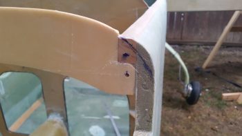
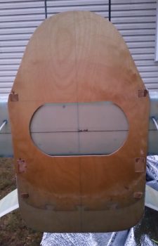
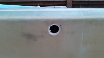
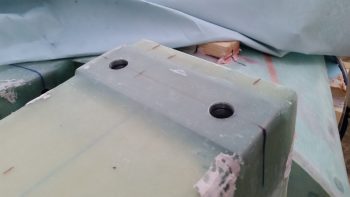
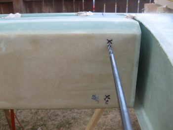
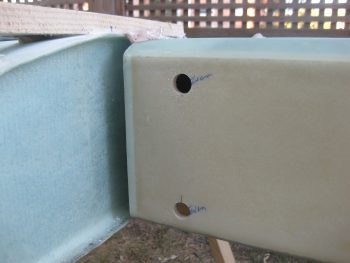
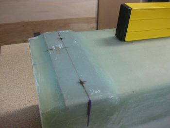
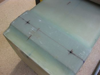
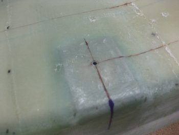
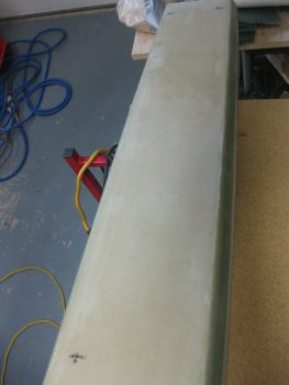
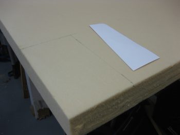
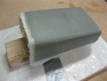
Today I started off clearing off the micro & finishing material from the top TE of the canard where the upper alignment tabs need to be glassed in.  I marked the spots first, for the right side, then the left . . .

Top right of canardTop left of canard

And then cleared out the finish and sanded it down in prep for 5 plies of BID.

Top right of canard clearedTop left of camard

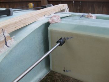
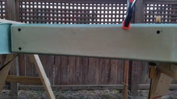
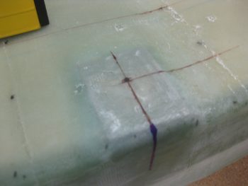
Although I didn’t take any “before” pics, I then did the same thing for the bottom side of the canard.  The alignment tabs will get 4 plies of BID on the aft/bottom side of the canard.

Canard bottom TE cleared for tabs

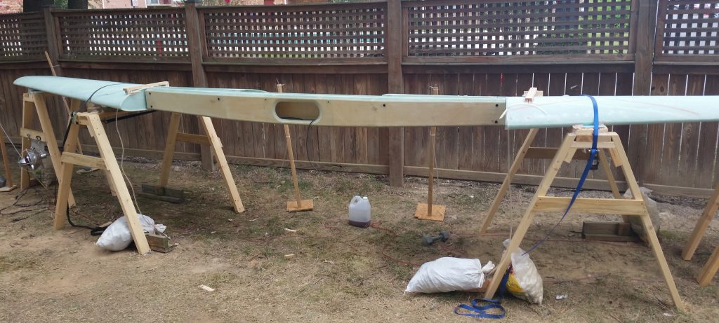
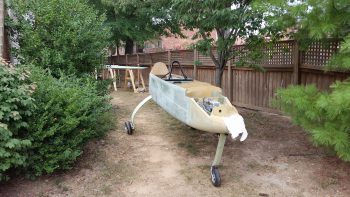
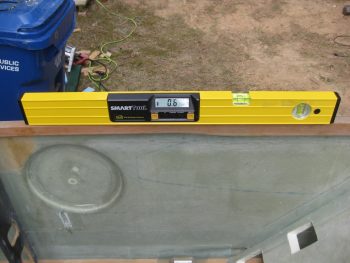
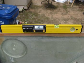
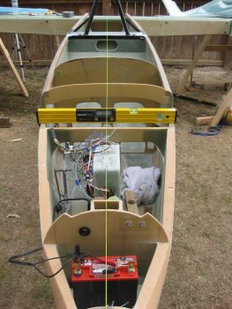
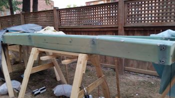
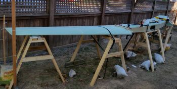
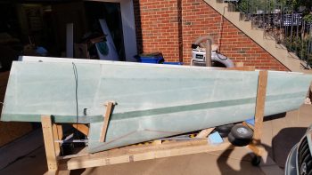
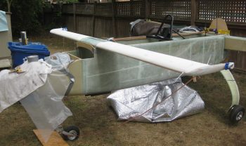
After checking the fuselage and spar to ensure all was still square, I then mounted the canard on the fuselage.  It seemed after the rain yesterday that the airplane had settled a bit, and it may have ever so slightly.  But my measurement across the aft ends of the longerons today revealed some spar-to-longeron mounting glass that was sticking up just a hair that would cause some erroneous level readings yesterday.

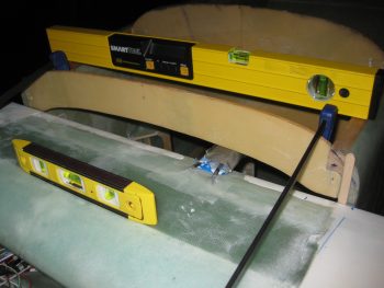
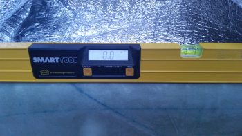
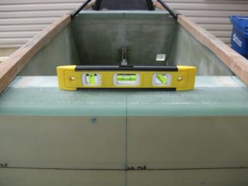
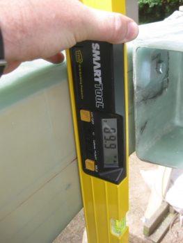
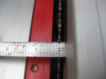
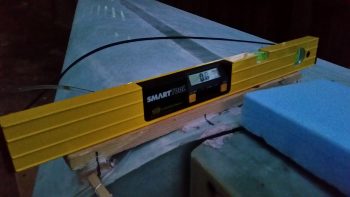
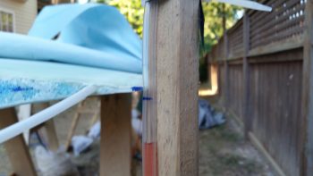
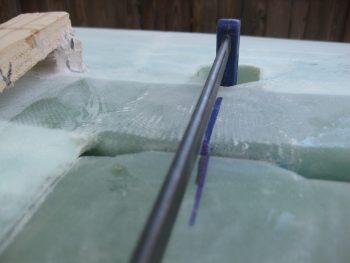
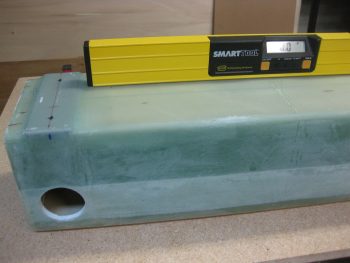
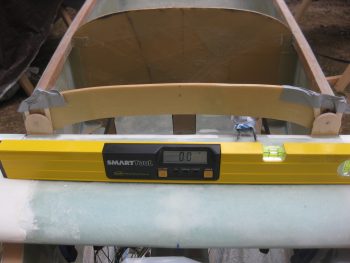
In addition, I used a very simple Side A-to-Side B water level on the canard today, as well as using levels to ensure that it is level from side to side.

Leveling canard

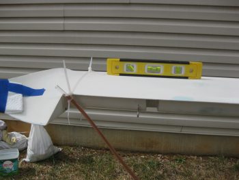
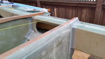
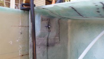
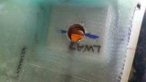
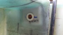
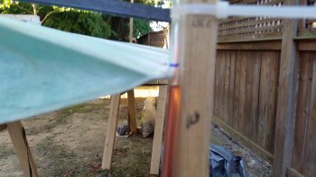
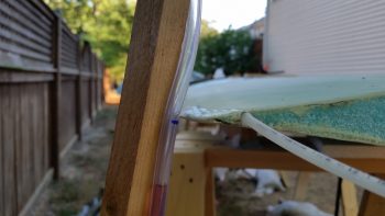
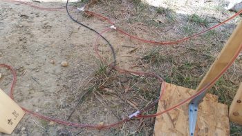
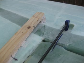
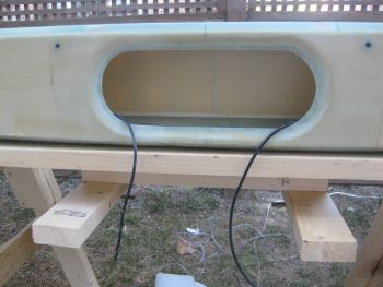
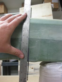
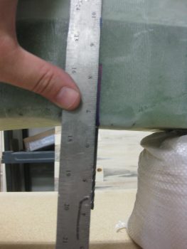
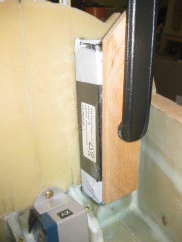
Here’s the right side water level showing it aligned with the canard TE.

Leveling canard

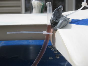
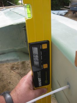
I still had to shim up the right side about 0.160″ to get the canard level.  A little more than my estimated 1/8″ required to offset my twisted fuselage, but I’ll live with it vs. rebuilding my fuselage!

Leveling canard with shims

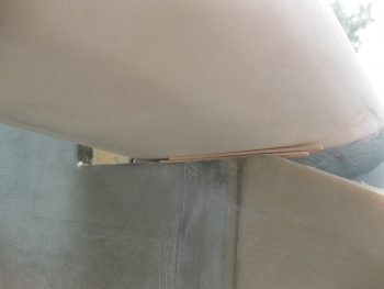
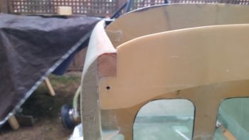
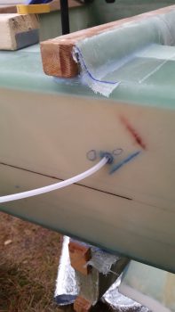
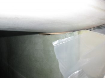
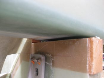
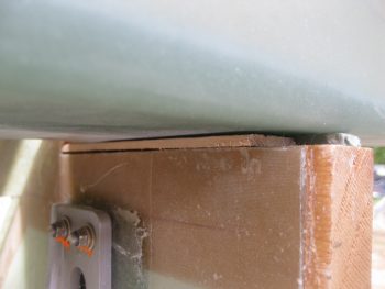
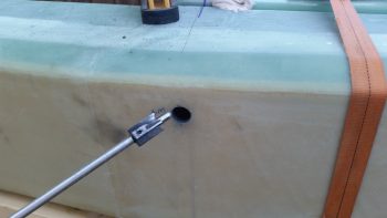
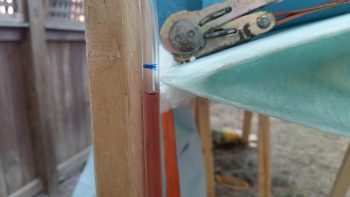
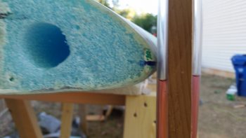
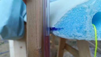
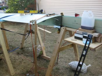
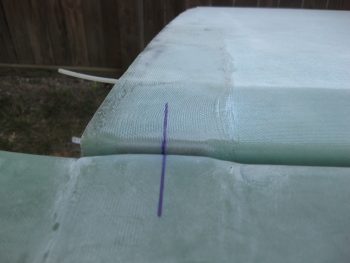
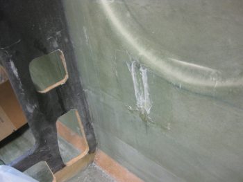
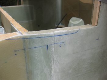
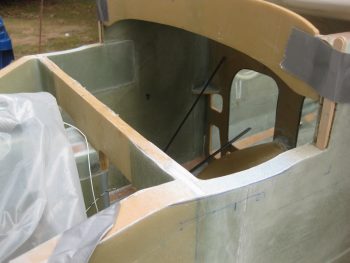
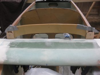
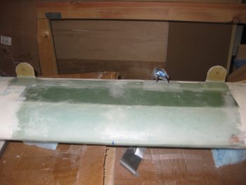
I wanted to show a pic of the gap between the canard and F22.  Today I plan on minimizing that gap by contouring the sides of the fuselage to match the bottom-side canard profile.

Gap betwixt canard & F22

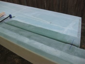
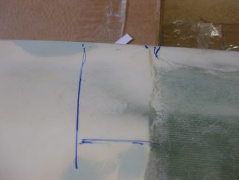
In fact, I dug out Template “E” to help me do just that.  First, I measure the normal lower profile of the canard, making a few alignment marks along the bottom edge of Template “E”.

Trimming nose sidewall

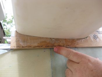
Then, I figured out how much I needed to lower the left side canard and marked those lines below the bottom edge line of Template “E”.

Trimming nose sidewall

I then moved the canard off the F22 “shelf” so that I could have access to sand out the bottom F22 profile.  This happened at least 20 times today, trial and error being the order of the day!

Is this mounted right?! ;)

With the lower marks in place, I simply matched the lower straight edge of Template “E” to the lower marks and then marked along the top edge of it which gave me the correct contour I needed for the bottom of the canard.

Profile for trimming sidewall

Profile for trimming sidewall

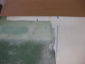
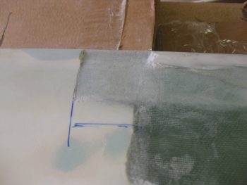
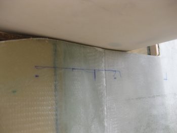
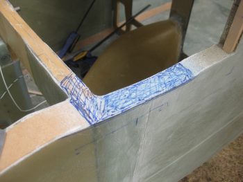
I then sanded down a significant portion of the area above the profile line above, and then kept checking for the high points (as shown below)… marked those and proceeded to sand them… with prejudice!  Again, this process was repeated countless times!

Sanding down sidewall for canard

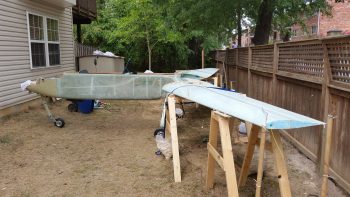
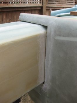
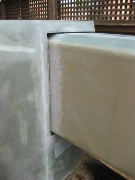
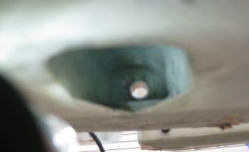
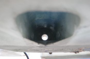
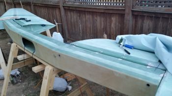
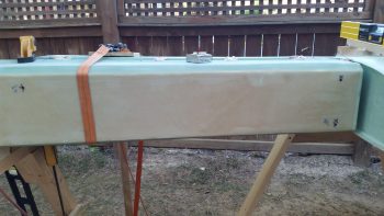
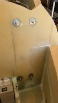
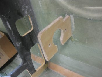
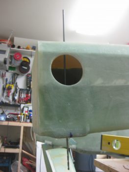
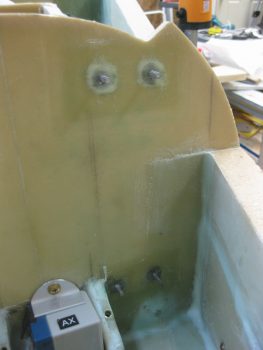
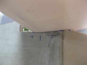
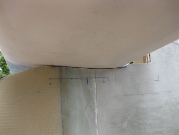
Here’s a shot of the fuselage sidewall cutouts.  Notice the left is much deeper than the right sidewall.  Which accounts for my lopsided fuselage (ahhh, the sins of the past….).

Profiling sidewalls for canard

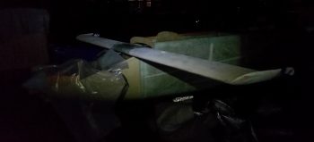
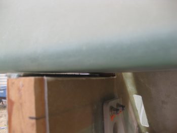
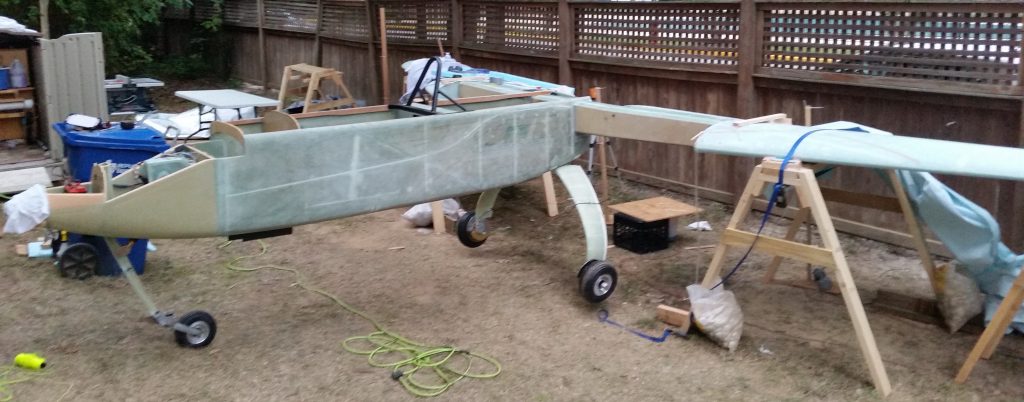
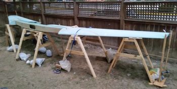
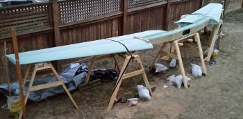
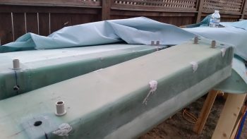
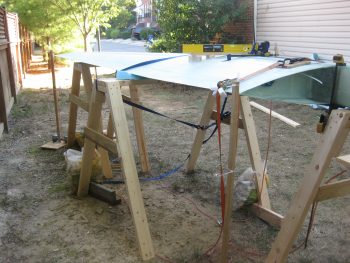
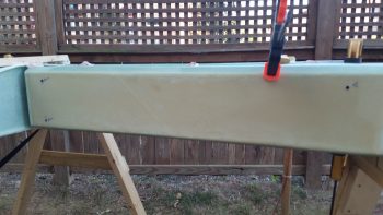
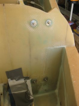
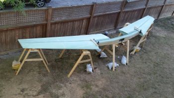
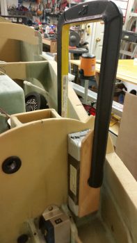
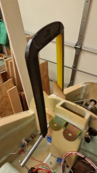
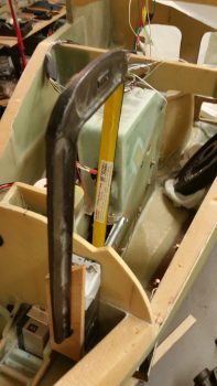
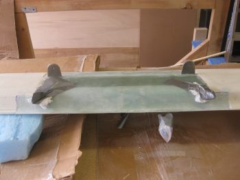
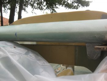
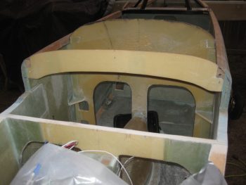
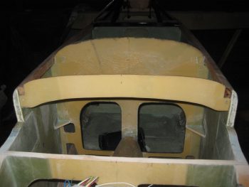
Here’s a couple more shots with the canard in place, from below.

Profiling right sidewall for canardProfiling left sidewall for canard

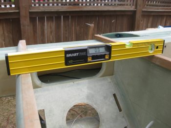
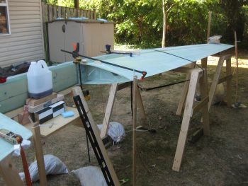
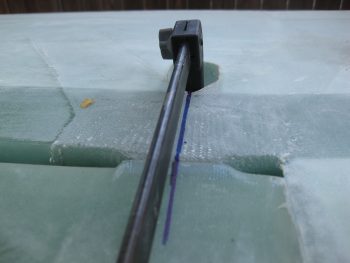
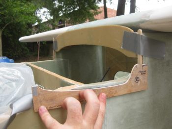
As I did hundreds of times today, I then rechecked the level on the top of the canard.  I was having a devil of a time getting the canard to stay level whenever I tweaked the incidence.  Of course the Roncz canard mounts with the lower tabs at an angle (unlike the GU canard), so keeping the bottom tabs tight wasn’t allowing me to get the canard Leading Edge (LE) nose up for the proper incidence.  The whole herding cats thing was in full swing here, so I decided to minimize my variables and work with the known quantities I had on hand.

So far so good!

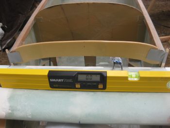
To keep the lower mounting tabs clamped, but then still be able to dial in my incidence by getting the canard TE down –thus, in essence the LE up– I decided to use my upper alignment tabs to do just that, align the canard!  So with some trial & error, and the main mounting tabs secured with clamps, I was able to use the height of the upper alignment tabs to dial in the correct incidence WHILE at the same time keeping correct sweep and level.

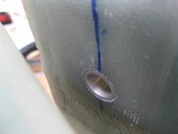
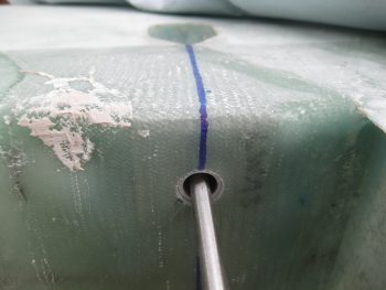
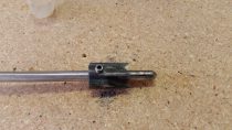
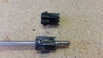
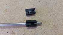
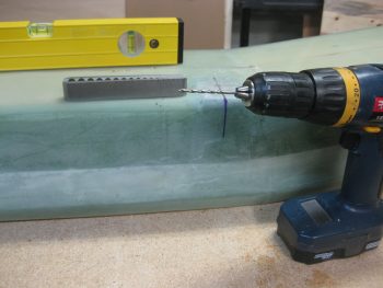
Of course this is NOT the order that the plans have you do all this, since in the plans you drill a #10 pilot hole through the lower tabs first, then mount the upper alignment tabs later. But the original plans are dealing with a straight-flat-bottomed GU canard that required no contouring of the fuselage sides.  I tried to prognosticate any future issues by doing it this way, and I couldn’t think of anything that would come back to bite me, so I proceeded to drill, trim & mount the Birch plywood (vs foam) for the upper canard alignment tabs.

Top alignment tabs in place

That kept the canard sweep & the level dialed in.  But I of course re-checked both to ensure all was good!

Still good . . .

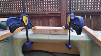
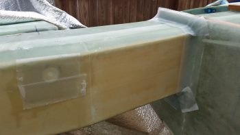
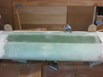
Continuing on with my working the known variables theme, I went ahead and glassed the front mating face of F28 to dial in my sweep with the newly mounted upper alignment tabs. I figure I’d work the canard install elements in the same way they are presented in Chapter 12 of the plans: SWEEP ⇒ LEVEL ⇒ INCIDENCE.

It may be a bit difficult to see in the pic below, but I then cut wedges in the foam sidewall uprights that are adjacent to F28.

Foam flox corners prepped

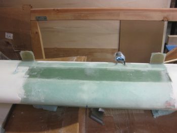
I then filled these foam wedges with flocro just prior to laying up 12 plies of BID on the left side (remember, I need to bring this side face out 0.155″) and then laid up one ply BID on the right side.  I was going to only layup 11 plies of BID on the left side, but went ahead and added one more so that I could the glass the right side with 1 ply of BID as well.

Flocro added to foam uprights

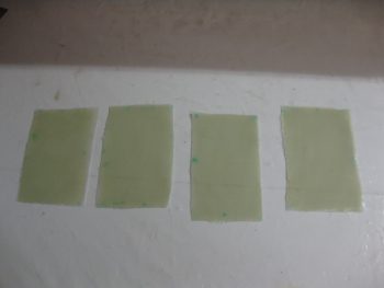
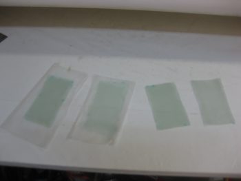
I had already wetted the 12 plies (in 4 sets 3 plies) of BID out before filling in the foam with flocro, so when I got back into the shop I merely squeegeed out the excess epoxy.

3 plies x 4 BID pads = 12 plies

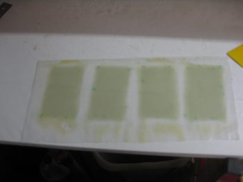
I then cut each set of the 3 plies of BID in prep for layup.

3 plies x 4 BID pads = 12 plies

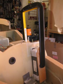
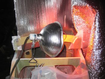
Here’s a shot of the heat lamp on the 12 ply BID layup.  Let’s just say that it cured fairly quickly!

12 plies laid up left side, 1 ply right

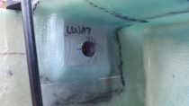
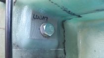
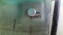
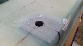
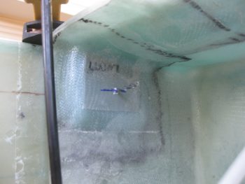
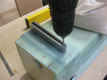
With the F28 bulkhead spacers in place, I then set my sights on glassing the front side of the upper alignment tabs with 5 plies of BID each.  I do have to state that my 5 min glue must be old because it was still a bit rubbery even after about 25 min.  I’m only going to layup the front side BID so that if need be I can heat up the tabs and move them forward or aft.  Not an optimal way of doing this most likely, but I really saw no other way of dialing in the incidence without spending an enormous amount of time making wedges for the lower mounting tabs…which just didn’t seem nearly as efficient as doing it this way.

Upper tabs 5-min glued in place

I sanded away the gummy 5 min epoxy on both tabs…

Left tab prepped for glass

Right tab prepped for glass

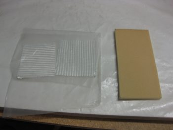
Then wetted out 2 sets of 3-ply BID and 2 sets of 2-ply BID to give me a total of 5 plies for the layups for both the left & right tabs.

2 sets: 3+2 = 5 plies BID

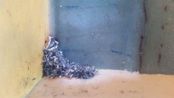
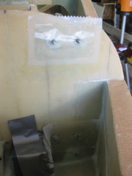
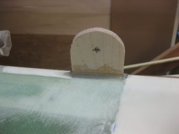
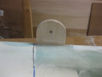
I then laid up the forward tab faces with 5 plies of BID, after troweling in some dry flox fillets in the mating corners.  I then peel plied the lower, horizontal part of the layup for a smooth transition into the canard top surface.

Left & Right upper tabs glassed

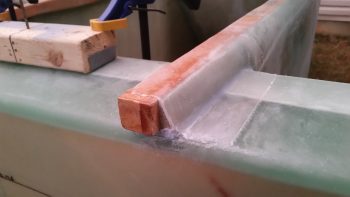
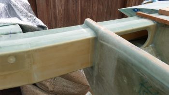
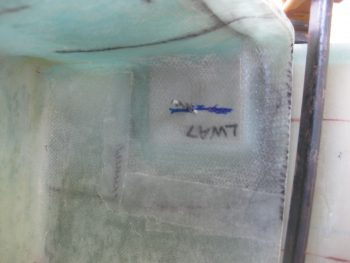
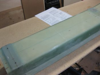
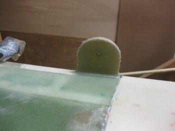
After a couple of hours, I then razor trimmed the upper tab glass.

Left & Right upper tabs razor trimmed

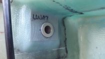
Here’s a shot of the left upper tab after I razor trimmed it.

Left upper tab razor trimmed

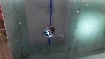
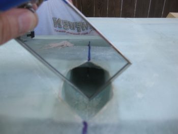
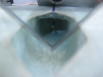
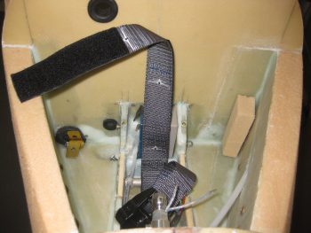
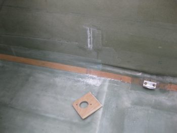
I did do one thing today not canard related: I used my Fein saw to remove the CS118 plate in the back seat in prep for moving the control stick mount just a hair inboard!

Removng CS118 for replacement

Tomorrow I plan on moving out as much as possible to get the canard mounted to the fuselage.

Much to do before Rough River!

Chap 12/14 – Canard Install/CS Spar

Today was quite the rainy day, at least up until about 1700.  I started out this morning by doing some much needed updates on this website.  That took well over 2 hours.  No worries though.  I had plenty of time to finish any administrivia tasks due to the rain forecast that kept slipping later as to when the rain was going to stop.  Originally the rain was due quit about 1300, but alas, that was not to be.

I used my time indoors to write out a detailed To-Do list for the canard installation.  I reread Chapter 12 of the plans, reread the install section of the Roncz Canard Installation Instructions, and then did some online crosschecking of some of my fellow Long-EZ builders’ blogs.

One thing I noted was on Dave Berenholtz’s blog, which was that he drilled holes into the AN970-4 washers that serve as the base for the K1000-4 nutplates — the entire assembly used for mounting the main 1/4″ canard bolts.  He drilled the holes as flox anchors, which is of course a common practice for Clickbonds.  Since there is understandably a fair amount of torque applied to these nutplate assemblies, I decided it was worth the 10 minutes to drill these flox anchor holes.

Flox grip holes in nutplate washers

After cleaning and organizing the shop for about a good hour, it was time to take down the canard from its storage perch on high.

Canard storage

I carefully took it down and set it on a bed of cardboard & scrap blue wing foam pieces.  I then spent a good half hour removing the elevators.

Canard removed from storage

Before hauling the canard out to the plane, I went ahead and drilled 3/16″ holes into the spruce longeron doubler (actual doubler not shown here, just F28).  As per plans, I’ll run a #10 drill bit into these holes, which are for inserting the 3/16″ canard alignment pins that the canard upper tabs mate to.  I’ll be using these alignment pins to mount the canard, but then I’ll modify the canard doubler by adding a wedge to square it off, drill this hole all the way through, then install a K1000-3 nutplate on the aft side of the newly extended/shaped canard doubler. The mechanism for keeping the top tabs in place will be a longer AN3 bolt that will simply screw into the face of the top mounting tab (with a washer of course), through the doubler and into the nutplate assembly on the aft side of the doubler.

Drilled alignment pin hole

You may note by the chicken scratch marking below that I missed the memo on shaping the front of the top longeron & fuselage correctly.  I will go back and correct that, I just wanted to get the canard mounted first.

Drilled alignment pin hole

Mike Beasley had this little contraption in his build photos, which is nothing more than a nail mounted on the marked center line of a scrap piece of wood, that is then mounted on the CS Spar’s CL.  This is an EZ method for having a standard reference point for helping determine sweep while mounting the canard.

Spar CL measuring point

I also wanted to temporarily mount the firewall, which required the trimming of the end glass hanging from the layup I did to mount the CS Spar to the fuselage.  I marked the glass, as you can see in the pics below, in order to have a reference line while cutting the glass.

Fuselage-spar glassFuselage-spar glass

I then used the Fein saw to trim up the dead glass.  After trimming the glass, I hit the edges with my sanding block.

Trimmed fuselage layup

It was then time to mount the firewall on the fuselage.  Uh, just one slight issue.  When I marked up the CS spar with the fuselage attached back in 2013, apparently I did it with the firewall off the fuselage.  Thus my lines were a hair farther out (say, 0.03″ to 0.04″) than if the firewall had been mounted in place. Doh!

Well, it was fairly tight, but with the help of a “persuader” (rubber mallet) the firewall went back on. Besides my one little spacing SNAFU, everything else with the firewall looks fine!

Firewall temp mounted

With the firewall back in place, and although it was nearly dark, I decided to get the canard onto the fuselage to at least collect some actionable intelligence for tomorrow.  I should note that besides having to spend half an hour getting the rainwater out of my “canoe” earlier, the soft ground also allowed the entire wing/spar/fuselage set-up to settle and thus move off the 0° mark in both the fwd/aft and left/right axes by a whopping 0.1°.  I’ll attend to the leans tomorrow, but for tonight I just wanted to get a general idea of what shimming I was going to have to do, and answer the question: “What size spacers (shims) do I need?”

Below you can see that for sweep I’ll need about 0.15″ (2 small Popsicle sticks) on the left side face of F28 for the canard to be even.  With these spacers in place, I got 114-1/16″ for both left & right sides from my spar CL reference point block to the outboard forward corner of the elevator cutout.  From the aft outboard corner of the wing I got 174″ on the dot on the right side, and about 1/32″ less than that on the left side.

Also, just as a point of note, I remeasured the aft outboard corner of both wings to the tip of the pitot tube and am still spot on at 247-5/8″ for each side.

Assessing shim/spacer requirements

To level the canard at the spar caps, it look likes I’ll need to add a shim/spacer about 0.165″ thick to the right side fuselage.  I’ll have to tweak this since I’ll most likely have to contour the sides of the fuselage immediately below the canard to get the canard to set in correctly, at which point I’ll merely make the right side contour 0.165″ higher than the left.

Assessing shim/spacer requirements

I realized I hadn’t got a pic of the canard on the fuselage, so even though it was fully dark outside, I took this shot.

Working canard install

My final official act of the evening was cutting a myriad of BID patches for the upper alignment tabs and the 0.15″ spacer that will be glassed to the left front of F28 (after determining actual spacer thickness & confirming the number of plies required).

BID for upper canard tabs & F28 spacer

With the majority of preliminary tasks out of the way, I’m fairly confident that I’ll be able to get the canard mounted onto the fuselage tomorrow.  If not tomorrow, I’d say definitely by the end of Wednesday . . . as long as the weather cooperates!.


Chapter 12 – Canard Mount Prep

Before I started sinking my teeth into prepping for the canard installation on the fuselage, I wanted to check how the fuselage longeron angles were looking.  Since there’s been some fairly significant swings in temps with the weather over the past couple days, I was curious to see if it had affected the front tire at all.  It didn’t and the fuselage is still locked at 0°.

Rechecking longeron levelAfter re-reading Chapter 12 in the plans on the canard installation, I then got to work on prepping as much as I could get in tonight for the upcoming canard install.

I started by rounding up my two AN3-20A bolts that will be modified to be used as the top canard tabs alignment pins.

Canard top AN3 alignment pins

I cut the heads off the bolts and then rounded them over some.  I’m not getting too particular here since I don’t plan on actually using these as alignment pins.  Instead, I’ll be going the route of a fair number of other builders who drill a hole all the way through the longeron doublers and then install a long AN3 bolt with a nutplate to secure the top tabs of the canard.  Reportedly, this makes installation & removal of the canard much easier, and I’m all about making things easier.

Canard top AN3 alignment pins

After finishing the alignment pins, I then started working on the nutplates that will be used to retain the main canard mounting bolts on the bottom mounting tabs.  Interestingly, Chapter 12 doesn’t describe any of the steps for making these nutplate assemblies, but instead merely refers the builder to the diagram on Page A7.  On A7 it shows a K1000-4 nutplate riveted to a AN970-4 washer.  The rivets actually appear to be drawn as Cherry pop rivets, but flush rivets are called for by part number.

To keep the nutplate centered on the washer, I used an AN4 bolt with a regular nut on the side opposite the nutplate.

Making canard mount nutplates

I then drilled the holes using the nutplate as a guide.  You can see that these holes are very close to the edge, but I doubt it really matters much since compression will keep the nutplate tight against the washer.  Let alone the fact that this all gets permanently mounted  to the aft side of F22 under a ply of BID.

Making canard mount nutplates

And here’s the final product.

Canard mount nutplates

Tomorrow it looks to have a good chance of being rainy during the first half of the day, so I’ll focus on prep work.  Then I’ll move into working on mounting the canard in the early afternoon.


Chapter 14/19 – Fuselage & Spar

Today was a light work day since I’m heading out to Dulles for the annual Airplane Pull & aircraft display.  I spent over an hour cleaning up the surrounding area around the airplane (I think I can say that now!).

I wanted to get a pic of what I didn’t last night, and that’s of the inboard holes filled with foam & micro and then glassed over with 2 plies of BID.  You can see that this is the initial shot & exactly what I saw when I pulled the heat blanket off for the first time.

Cured Fuselage-to-Spar glass

Here’s a shot immediately following me pulling all the peel ply.  I haven’t cleaned up the layups so it’s all stiff a but rough.  I am, however, very happy with the quality of the layups.

Fuselage/spar peel ply removed

Since I found out last night that we may have a chance of thunderstorms this weekend, and I’ll be very much out & about, I decided to really ensure that the tarps were secured well to keep the sun off the raw composite surfaces, and to minimize any moisture… especially in the nose — which I covered with plastic.

Fuselage-Spar-Wings Covered

Tomorrow won’t be much of a build day either, but I do plan on getting a fair amount of research and a final review in on mounting the canard.


Chapter 14 – Mounting spar to fuselage

Today I hit another HUGE milestone in my Long-EZ build!  I mounted the fuselage to the CS Spar/Wings assembly!!

Before I get into the fuselage stuff, just a quick side note that I used some of the left over flox from installing the LWA9s to repair the power cord wrap tang on my miter saw that I broke getting it out of the shed yesterday.  I let it cure overnight and it looks great.

Leftover LWA9 flox repair

First, I spent about an hour organizing & cleaning the shop.  I then spent over 45 minutes cutting the BID tapes for securing the fuselage to the CS spar.  I also cut out the 3″x3″ BID pads to cover up the inboard 5/8″ pilot holes I drilled on the CS Spar to facilitate drilling the wing bolt holes.  Since the front face of the spar makes up the aft wall of the fuel tank, then the inboard holes clearly need to be re-glassed.

Fuse to spar BID tapes

To get the fuselage into place on the spar, I needed to get rid of the sawhorse out from under the spar.

Removing spar sawhorse

To do this with least amount of hassle and disturbance, I simple cut the 2 front legs of the saw horse.  Since I had routed the water level lines through the legs of the saw horses, the most expedient way of freeing the water level tubes was to simply cut the cross members of the sawhorse.  You can see all this in the pics below.

Voila!  Here’s the saw horse with its front legs trimmed down and easily removed out from under the spar without disturbing the spar.

Removing spar sawhorse

Here are the wings & CS spar, with the spar out in free space and held in place only by the wing bolts.

Spar sawhorse removed

I then needed to get the fuselage out to the wings/spar setup.  Here’s my fuselage on climb out! Of course I really lifted the nose high to get the table out from under it.

Aim High!

This is the first time my fuselage has ever ventured out into the world (aka “beyond the garage”).

Pulling out the big guns!

Looks “long” with that nose on there.  Love it!

Mobile fuselage!

Getting ready to back ‘er up.

Fuselage on the move!

Doing a little 3-wheelin’!

Traversing narrow paths . . .

Over the storm drain & through the woods . . .

Through the woods . . .

Ah, this is where this belongs!  Looks awesome with the fuselage set in place on the spar. It was pretty EZ to line it up because I had taken some time when I mocked this all up in Germany back in 2013 to align the fuselage on the spar, at which point I marked the spar with alignment lines.  I had actually forgotten about those alignment lines and seriously didn’t even notice them until today.  What a nice surprise!

Spar glassed to fuselage!!

Spar is still level Left & Right.

Checking CS spar level

Here’s me re-checking the CS spar level, left & right sides.  I don’t have pics, but the incidence on top of the spar looked spot-on as well.

Checking spar vertical levelChecking spar vertical level

Ah, nice & level across the longerons!

Checking longeron level

Now, the nose was a bit high so I ran into the garage, got my battery and mounted it in the nose.

Checking nose level

I then raised the nose gear until the longerons were level at 0°.

Ah, better!

Then rechecked the left longeron to confirm 0°.

Verifying other longeron

I tried to use the laser level to shoot down the CL of the fuselage, but it was just too bright out to see the laser mark, although I could see well enough to line up the spar with the back of the front seat CL mark.  I then ran a string to confirm all was centered between spar & fuselage.

I do have to admit that a persistent problem that has plagued me all these years is that my fuselage has a slight twist to it.  It essentially “droops” down to the front left just a hair.  It’s about 0.2° low on the left side at F22.  There’s nothing I can do about it, and I even tried to load up the fuselage with offsetting weights to cure (pardon the pun) this problem when I post-cured the fuselage, but it made scant difference.  The main issue it causes is with mounting the canard, and it simply means that the canard may be lopsided a hair when mounted to F22.  However, we’re talking about the canard being mounted maybe 1/8″ higher on the left side.  This issue is one major reason why I want to mount the canard with the wings & spar in place so that it will be straight in relation to the wings!  Not a horrible issue, just one to note.

Checking spar/fuselage centerline

All-in-all, it only took me about 30 minutes total to align the fuselage with the CS Spar.  In addition to the steps above, I made a whole slew of measurements from the aft outboard corner of the spar to instrument panel & F22.  Measured from the front outboard end of the wings to the the panel & F22.  I also measured the aft outboard TE of the wing to the very tip of pitot tube: 246-3/4″ on the left, and 246-1/2″ on the right.  I looked at all my other measurements and noted that indeed my fuselage was tracking just a hair to the right.  A very small nudge on the nose and all my measurements were pretty much exact, if not within a 1/8″ of an inch off at a point or two.  I remeasured from the aft outboard TE of the wing to the pitot tube and got a perfect 246-5/8″ on each side.  It was clearly time to get down to brass tax and get this fuselage mounted while my fuselage-spar alignment was spot on!

As I started the actual attachment process, one thing that I had going on –since I made the spar cutouts on the aft fuselage exactly to the plan’s dimensions– is the foam on the fuselage is higher than the spruce firewall/gear hard point (LWY).  I could just fill this area with flox, but I’d rather use a thin piece of spruce as a spacer. I measured the gap at  0.150″.

Gap under CS SparGap under CS Spar

I grabbed a good piece of scrap spruce and then set up my saw for right around 0.150″ (or ~5/32″).

Cutting under-spar spacers

And made two 5.7″ spacers to go under the spar.  I would have preferred 6.5″ long spacers, but this piece of spruce was the best I had available, so I used it.

Under spar spacer

In prep for glass, I sanded all the areas that would be getting BID tapes.

Sanding in prep for glassSanding in prep for glass

I then laid up the BID tapes!

My fuselage & CS spar are now officially one assembly!!

Spar glassed to fuselage!!

I’ll of course wait to layup any glass on the inside longerons until I mount 10-ply BID pads for the engine mount extrusions.

Spar glassed to fuselage!!

And here it is, the wings mounted to the CS Spar now mounted to the Fuselage!  Yes, it’s bit cluttered around the plane, but I’m in the process of building it . . . if ya haven’t heard! ha!

Also, for those folks concerned about me not using a sawhorse up front and relying on that “squishy” front tire to maintain the fuselage level, it did fine.  To account for that, I used fast hardener –which let me tell you, is fast!– and worked in phases starting from the bottom spar connect points moving upwards.  I also rechecked the level and center measurements a number of times.  Hours after I was finished it was still sitting at 0º on the longerons.

Spar mounted to fuselage!

I then cut a 1-1/2″ x 1-1/2″ piece of 2024 Aluminum for one of my upper engine mounts.  I trimmed it down on the table saw to 1-1/4″ on the leg that will be sticking upright as it is mounted on top of the CS Spar.  Just a personal preference to not have such an oversized extrusion mounted in the cockpit area.

img_3377

I then cut the inboard 5/8″ pilot holes on the spar –used for drilling the inboard wing bolt holes– out to 1″ since the edges of the 5/8″ pilot holes were really oily & dirty from all the metal shavings & the spotface pilot rod rubbing against it.

Recutting inboard but holes for glass

Recutting inboard but holes for glass

Here are my 3″x3″ pre-pregged 2-ply BID pads, and the 1/4″ foam I used to back fill the holes.

img_3378

I don’t have any pics yet, but I micro’d in the foam into the holes and then glassed up the 2-ply BID pads over the holes. It was dark and I really couldn’t get any decent pics of this, so I’ll get them tomorrow.

I then set up a heat blanket & a couple of heat lamps on the new layups.  I won’t be working tomorrow since I have my EAA meeting and then will be heading to Dulles for an airplane display event.

On Sunday evening amidst watching football I’ll be prepping to start mounting the canard on Monday!


Chapter 19 – It’s Official!

Yes, my friends, the wings are officially mounted!  Today I bolted the wings to the CS spar for the very first time!  How?!  Well, read on dear readers!  Read on . . . !

Last night I was in a bit of a quandary.  I had been thinking late into the evening on how exactly do I trim the LWA9 bushings to length?  In the plans it says to “face” them… not sure what that is.  I don’t have a lathe, but I do want some nice cuts on the “face” of these LWA9’s.  Hmmmm.  I attempted to do some research online, but to no real avail. Everyone in the universe seems to know how to trim these suckers up except for me!  (I guess this is a common occurrence when building an airplane, eh?!).

So I did what I quite often do when faced with a problem… I went to breakfast!! (this morning, not late last night…).  Ah, it was there that I wondered upon the idea of using a pipe/tubing conduit attachment as a clamp to hold the LWA9 in place.  I would then use my mojamma Bosch miter saw to cut these suckers.  Yep, a plan was developing!

So I went to Home Depot and picked up some of those pipe/tubing conduit attachments. The smallest they had was 1/2″, so I picked up some friction tape as well.  I wandered around the Aviation Electrical section for a few more minutes to see what I could find interesting, when I happened to sight some Adel clamps hanging at the end of the aisle. Hmmm, could also be an interesting proposition . . .

When I got home I “clamped” a couple LWA9s to a scrap 2×4 piece, and then rounded up some -10 Adel clamps & mounted those as well.   I call it the “poor man’s lathe.”

LWA9 Cutting Block

I then pulled out the Bosch mojamma miter saw to see how this all would work.

Poor Man's Lathe

Ready!

Ready to trim LWA9s

Well, it worked great for the LWA9s in the Adel clamps!  Not so much for the pipe/tubing conduit attachments…. Ooof!  Check out the second LWA9 from the left.  This was round #2 and I took out the 4 freshly cut LWA9s and replaced them with 3 new ones and this mangled one from an attempted cut while mounted in the pipe/tubing conduit attachment.  Luckily it didn’t do any damage inboard of my original cut line, so once I trimmed it in the Adel clamp, there was no trace of the horrors that it had just previously endured!

Redo on conduit clamped LWA9

And here are those same 4 LWA9s after getting a trim.  I tell ya, with a nice sharp saw blade this thing works like a champ!

Trimmed LWA9s

While I had the saw out, I went ahead and cut my lower 3/16″ thick angled 2024 engine mount extrusions.

Cutting lower wing mount extrusions

Here you can see I cut the lower engine mount extrusions to the plan’s 8″ length.

Lower wing mount extrusions cut

In addition, as I was brainstorming (just prior to trimming the LWA9s) on all the stuff I needed to cut, to optimize my saw time, I worked up a quick off-the-cuff solution for a bracket to mount inside the CS spar in order to reverse my outboard wing bolts.  This has them essentially permanently mounted sticking aft out of the spar.  The report from many builders who did this is that it makes mounting the wings infinitely easier & faster.  James Redmon –from Berkut 13 fame– did this on his bird, a pic of which I shamelessly stole from his website:

James Redmon's Berkut wing bolts

Note that the pic above is of a Berkut, not a Long-EZ, but the concept is the same.  However, as with many things on this build I had to go and complicate it by adding in my 1″ electrical cable conduit hard-mounted inside the spar.  That means instead of simply screwing in a single piece of U-channel, I’ll have to build a more intricate one with a “bridge” to cross over the electrical conduit.  The smaller pieces that will make up one side of the bridge are what I’m cutting below.  Consider this a teaser on the ‘Reverse Wing Bolts Mod’ . . . more to come later!

Cutting reverse wing bolt u-channelReverse wing bolt u-channel cut

Moving on, here’s a shot of all 12 LWA9s after I sanded the trimmed face of each one, and then quickly chamfered the outer & inner edges of the new faces.  I also gave them a good bath in Simple Green.

Trimmed LWA9s

When I went back to the spar & wings my first task was to pick up the spar and flip it around to give me better access and a better angle to work on installing the LWA9s.  And then the darnedest thing happened!

As I was lifting the spar up over my head, it shifted hard to one side and I almost dropped it. I got a hold of it as I was facing the low end of the spar just above the ground. And that’s when I saw a TON of water pouring out one end of it!  Not only was it water, but the aforementioned aluminum soup (which I had cleaned out)!  Of course at that point I tipped, flipped and swirled the CS spar every which way but loose (like what I just did there!) to get all the water out.

When I finished on the spar, I checked out the end of the spar where the water came out, and this is part of what I found!  I went back into the shop to retrieve my shop vac and proceeded (again) to vacuum out this beast.

Leftover shavings in CS Spar

After giving the spar and the wing bolt hole channels a good cleaning, I then finally got a shot at what I was originally looking for in the first place!  The left wing’s upper outboard LWA9.  I was checking it for fit since I can’t get my hand up there to feel the edge to ensure that it either matches or is lower in height than the surrounding hard point extrusion.

Spar's left top outboard LWA(9

Here’s the left wing’s inboard LWA9, nice & flush!

Left side wing root LWA9

And here’s the left wing’s upper outboard LWA9 test fitting… lookin’ good! (I have it installed backwards to check the depth as you see in the pic.  Final install was the correct orientation).

Left outboard wing upper LWA9

Out of 12 bushings I only had to recut one, and that was the left inboard LWA9 in the CS Spar.  Actually, I had to cut it 2 more times before I finally got it to the right depth!

Recutting left Spar inbd LWA9

Here’s a couple shots of the left wings’s lower outboard wing bolt hole channel with an LWA9 mounted in the bolt hole.  The upper pic shows the bolt hole channel a little bit better, while in the bottom one you can make out the LWA9.

Left lower outboard wing LWA9Left lower outboard wing LWA9

Here are the temporary wing attach bolts.  I don’t know where I got the info from, but like a maroon I already ordered the big bolts, and guess what??  Yep! Way too short!  So even my mock-up bolts were way too short so I had to run to Home Depot to buy 2-1/2″ bolts just before I got started on all this!  Once I got home, I quickly waxed all the bolts with Turtle Wax.

Temporary wing bolts

Here are the measurements of the matching LWA9s back-to-back, which of course is what is used to determine required wing mounting bolt lengths.

………………………….LEFT WING         RIGHT WING
Inboard                             1.67″                      1.66″
Outboard Top                   1.59″                      1.58″
Outboard Bottom             1.62″                      1.61″

With my LWA9s squared away, I then started on installing all 12 LWA9s and bolting the wings to the CS spar for the very first time!!!

I mixed up some MGS 285 epoxy and threw in just enough flox to give it a tad bit thicker consistency.  I then inserted all the CS Spar LWA9s with the wet flox.

I then mounted the LWA9s in the inboard wing bolt holes, slid the inboard bolts in place and lightly tightened a nut in place to ensure the spar stayed put.  I then mounted the outboard LWA9s/wing bolts and tightened them up.  Thankfully, there were no real issues with installing the wing bolts.

CS Spar's LWA9 bushings

And here’s a shot of my wings now hard-mounted to the CS spar!!!

Initial wings bolted to CS Spar

And the same thing from a different angle… again, amazing feeling getting this done & under my belt!

Initial wings bolted to CS Spar

I then rechecked the water level markings and also the wing level board…. seriously, all the numbers still looked really, really good!

Wing level recheck after bolted

Here’s the final shot of the evening with my wings.  Since it’s starting to cool way down at night, I threw some heat blankets over the wings and fired up a couple heat lamps to keep this thing cooking all night long!

Heat lamps on wings/spar LWA9s

Tomorrow I’ll be working to get the fuselage mounted to the CS spar (at a minimum, prepped to be mounted!).  I’m thinking it’s going to be yet another long day!


Chapter 19 – Bolt holes drilled!

I started off today right where I left off yesterday . . .  drilling, drilling, drilling, drilling, and then drilling some more.  Let’s say about 5 hours total today, with over 2 hours last night!

Yep, I was one of those builders who used the plan’s spotface tool to drill this sucker out. I can say now that it’s over that I’m glad I used it, because the holes are perfectly round and beautiful!  That being said, if I knew of another really good way (yes, I’ve read about modifying hole saws, reamers and the like, but I went with with the spotface tool… Ironically because the 5/8″ bi-metal hole saw bit I ordered didn’t arrive in time!  ha!)

One of the main reasons it takes so long to drill these holes is heat management.  Yes, it may be a lot better with a different cutting/drilling tool, but with the spotface tool I would drill for 10-15 seconds, blow compressed air into the hole for 20-30 seconds, and then (starting today) wet it down thoroughly with cold water from a water bottle sprayer.  These holes definitely get hot, especially due to the torque!  And this was even more pronounced the deeper into the hole since the entire side of the spotface cutter was contacting the sides of the hole.  Tons ‘o heat generated in this endeavor my friends!  In fact, my cordless drills were struggling when I started out using them (my corded drill was buried away in my shop) and I even smoked one after pushing it too hard… even though I was rotating through 5 different cordless drills!  And let me state for the record that the newer generation Ryobi Lithium batteries are a joke, many of them could barely make it through a couple rounds of holes.

Nonetheless, I eventually got the holes drilled!  Whew!  What a feeling . . . especially when they land in the right spot!  Below is the first light at the end of the tunnel I saw late this afternoon.

Spot face tool peeking through!

Luckily I bought another spotface from McMaster-Carr before I started, because the original one I had was worked HARD!  The swapping of the old to new spotface was a bit of challenge unto itself.  I had to drill out the set screw that was covered over with metal, and then the spotface didn’t want to come off the guide, as if it were welded in place.  I eventually got it of course, but not without some wailing and gnashing of teeth!

Here’s a staged photo showing the spotface just about to go in and do some real damage!!! Ok, maybe just a little bit of damage . . . ahem.

Final holes drilled!

And here’s the other side.  I took this shot to show all the layered extrusions that make up the inboard hardpoint on the wing (this pic was taken later after I pulled off the CS spar).

Hard point extrusion layers

As I drilled out the inboard wing root bolt hole channels I cleaned them up and then test fitted an LWA9 bushing into the hole to see how it fit.  The LWA9 bushing fit perfectly in each side.  I then slid in one of my test bolts just to see how it would fit as well.  With the bolt I was specifically curious to see its spacing since my hole is actually a hair low on the extrusion.  But as you can see, there’s plenty of “meat” below the bolt to hold it in place.  I have no doubt these hard points are 100% the strength of what they should be.

In the pics below, the top row is the right wing root and the bottom row is the left:

Below is the after affects of drilling out the inboard wing mounting bolt holes.  Since I was using both air and water to clean out & cool the holes, it created an “aluminum soup” on the inner floor of the CS spar.

Aluminum bit soup

Also, here’s my abstract airplane art shot that I took using all the extrusion rings that I drilled out during this very long process.

What I removed from the holes!

I also wanted to document my water level marks for each of the points of the wing that I was checking.  The blue lines you see on the tubing are marked for waterlines other than the 17.4 WL.

Below is the inboard TE of each wing at BL 23.  Since this curves up just a tad to intersect the cowling, according to plans it’s at WL 17.5.  Just as a note, the distance between my two inboard TE corners was exactly 46″…. I like it!  Also note, that although the levels at the following points may not be aligned perfectly with the water line (or the blue line), they are very close and also match pretty darn symmetrical between right & left wings.

R-Wing TE BL23 water level markL-Wing TE BL23 water level mark

Here’s the outboard TE at BL157, with the right wing in the top pic.  Since the wing slopes as it goes outboard on the TE and down from TE to LE, this WL sits at 18.35 (again, the blue line).  So even though these look terribly high compared to the actual reddish water level line, they are within about 0.1″ off from being spot on.  Another point I need to make is that the red water level fluid is a bit low after sitting out all night long (you can really see this in the pics above since the blue line is a bit farther off than 0.1″).

R-Wing aft corner BL157 TE water levelL-Wing aft corner TE BL157 water level

Finally, the outboard LE at WL 17.4, which of course is the water line for the entire leading edge.

R-Wing outbd LE BL157 water levelL-Wing outbd LE BL157 water level

After rechecking and verifying my water level marks, it was time to remove the CS spar from the wings (aka “Bondo Destruction Time”).

Prepping to remove bondo

I removed all the bondo that I could get to on the top & bottom of the CS spar & wing junctions.

Bondo removed

I then cracked the CS spar loose and turned it on its face.  Then I got to work removing even more bondo.

Cleaning up aft side spar bondo

Here’s the right side of the upended spar requiring more bondo removal.

Cleaning up aft side spar bondo

I also washed all the gray aluminum grime from around the bolt holes with Simple Green and was very happy to find no delams!

Clean holes & no delams!Clean holes & no delams!

I then started work on the LWA9 bushings.  I put them by their respective holes and marked them up so that they would match the depth of the specific hole they were being cut for.  I then measured the depth of each hole using the recommended hole depth checker identified in the plans [NOTE: As I was cleaning up the next day I found a depth checker in the bag that the Cozy Girrrls shipped the LWA9s… oh, well!  Just a point of note that if you buy these from the CG’s that it comes with a depth checker, so you don’t have to spend an extra 5 minutes making one!]

Sorting out LWA9 bushings

I then packed up all the tools for the night, and marked up all my LWA9s for trimming.

Sorting out LWA9 bushings

Tomorrow I’ll trim up all the LWA9s and then mount them in the spar & wing bolt holes with flox… and my temporary wing bolts.


Chapter 14/19 – Right of Passage

I started off today reviewing the plans on installing the wings to the CS spar… to ensure I don’t miss anything.

Then I constructed the water level system.  I have 2 shots of that below, just to ensure some clarity.

Water Level Tubing

Water Level Tubing

The jug in the foreground is the actual reservoir for the water level system, while the milk jug in the back is simply the Kool-Aid colored fluid (plus a little dish soap) for the water level.

Filling up water level jug

Here’s a closeup shot of the water level reservoir.  It’s a bit out of focus, but you can see one of the two lines coming out of the bottom of the water level reservoir jug with a grommet installed to seal it all up.  Also, note that the water level in the main reservoir is matched level with WL 17.4.

Water level jug tubing

Here’s a quick video I shot detailing the general features of my water level system:

The water level is an amazing tool that allowed me to really dial in the rigging of the wings to the CS spar.  Below is a shot of the Right Wing after I leveled it out and bondo’d it in place.  Let me tell you, the term “herding cats” that all the other builders use to describe this part of the build is amazingly appropriate.  It took about 2 hours per wing to really get all the variables synchronized to get the wings to level out appropriately.  I remained about 0.15″ high on outboard leading and trailing edges, but I’ll take that!

Right wing rigged, set & bondo'd

Here’s a wide angle shot showing the right wing rigged and work on the left wing to get it set.

Leveling wings

And here’s a couple shots of the left wing as I worked to get it level.  The left wing took significantly longer than the right wing, and after getting all but the front inboard edge aligned, I finally (out of curiosity) set up the laser level to check the leading edges of both wings.  For some reason my level board was way off on my left wing, so I committed a cardinal sin and went with the good level measurements on the other 3 corners, and used the laser level to fix the front corner (the BL 55.5 jut out) to match the right wing.  One overriding reason I did this is the statement in the plans on pg 19-18: “Incidence must be set exact, or the airplane will roll.”  Now, at that point the plans are talking about the setting of the level boards to 0°, but I also take that statement to mean the wings leveled in concert & in comparison to each other.   Regardless, it certainly made everything work and align well on the left wing after I made the decision to use the laser level to match the leading edges vs going with the level board.

Rigging left wingRigging left wing

Here’s a shot of the right wing after it was secured in place by bondo.  Both my wings are about 0.15″ high on the outboard end, but as I measured everything I concluded that my wings are definitely symmetrical!

Right wing rigged

After I bondo’d the left wing, I prepped for drilling the 1/8″ pilot holes through the front spare face and into the wing hard point extrusions.

Below is a shot of the right wing’s inboard extrusion.  Since I had to lift the inboard wing roots as high as they could feasibly go to align the wings, it lifted the embedded extrusions as well.  Thus, the drilling is a little low to what I want on the inboard wing extrusions, but not too serious.  I will also try to cheat the hole upwards as I drill out the bigger extrusion holes.

1/8" pilot hole drilled RIGHT

Here’s the same exact thing on the left side.

1/8" pilot hole drilled LEFT

I will tell you one area that I’m ecstatic with, and that’s that I was able to get the 1/8″ pilot holes pretty much in the exact center of all the wing bolt troughs!  *** whew!!!! *** I think this honestly must be the most anxiety that a canard builder can feel is when drilling these holes!

1/8" pilot hole drilled outboard

This shot is a bit blurry, but you can see the drill bit in it.

1/8" pilot hole drilled outboard

After all the 1/8″ pilot holes were drilled and verified, I then opened up the holes to 1/4″ as called out in the plans.

Drilling 1/4" pilot hole outboard

Below is both the right and left spar faces with 1/4″ pilot holes.

1/4" pilot holes drilled1/4" pilot holes drilled

I then grabbed my 5/8″ spot face tool and opened up all the forward spar face holes with it.

Drilling 5/8" pilot hole

Here’s the right side holes opened up to 5/8″.

5/8" pilot hole drilled

And another wider angle shot of the right side CS spar front face with the wing mounting holes opened up to 5/8″

5/8" Spot face holes drilled

After opening up the front spot face holes I then drilled the CS spar and main wing extrusion holes for a bit over 2 hours.  I was having drill & drill battery problems, plus it was dark, so about 2100 I called it quits and packed up all my gear.  I figure I got anywhere from a half to 3/4 of the way through on these holes.

I have another spot face bit, so tomorrow I plan on getting through the holes in no more than about 2 hours.  From there I’ll trim and then flox in the LWA9 wing bolt hole inserts & let them cure in place overnight.


Chapter 14/19 – Begin Wing Mounting

Today was a heavy prep & work day, both in regards to mounting the wings to the CS spar and in finishing up my miscellaneous tasks from yesterday . . . so let’s get to it!

Of course the battery tray was nice & cured this morning…

Battery tray cured

So I pulled off the peel ply, then the protective tape on the battery itself.  I then worked the battery tray off the battery.

After I got the battery tray removed (and yes, it’s a tight fit!), I then pulled the tape from inside the battery tray.

Battery tray tape removal

The result was nice in that there was no SNAFUs!

Battery tray ready to trim

I then quickly set the battery back in the tray to test out the fit… nice & snug!

Battery tray test fit: Good!

In my expert opinion (ha!) I’d say the tray looks a bit rough, so I marked it up for some trimming.

Battery tray marked for cutting

I also marked the tool box for trimming as well.

Tool box ready for trimming

I then grabbed my Fein saw, the battery tray and the tool box and took them all outside for a trim.  Here’s the result:

Battery tray & tool box trimmed

I’m really happy with the way the battery tray turned out.

Battery tray ready for install!

I then got to work to lay up the aft wall of the tool box with 3 plies of BID.  Since I want a square corner on the back side of the tool box (where it hangs on the Napster bulkhead), I need flox corners (actually, I’ll be using Flocro… heavy on the micro).  So I marked & cut those out.

Prepping aft tool box

I whipped up some epoxy and some Flocro, with about 70% micro to 30% flox and filled in the wedged Flocro corner troughs.  Also, as you can see in the pic below just above the tool box (light green rectangles), I cut up 2 sets of 2-ply BID and pre-pregged them to lay up over the IBBS Clickbonds.

Flocro corners & IBBS BID top

I laid up the 3 plies of BID on the aft wall of the tool box and then peel plied it.

Aft wall tool box 3-ply BID

As for the IBBS Clickbonds, below are some shots of the IBBS being removed from the floxed-in Clickbonds.

IBBS Clickbonds floxed in placeIBBS Clickbonds floxed in place

I then sanded all around the Clickbonds and cleaned them up to ready them for the 2-ply BID layup.

IBBS Clickbonds sanded

Here’s the BID layup that extends about 1″ from each Clickbond stud.  I also peel plied the glass to give a good transition.  To make it “form fitting” for the IBBS unit, I put the pre-preg plastic back in place.

IBBS Clickbonds with 2-ply BID

I then reset the IBBS unit and clamped it back in place like I had it last night.  This will ensure that the BID immediately around the Clickbond posts lays down nice, flat & tight.

Remount IBBS for press fit Clickbonds

I took a break and ran up to Home Depot & to grab lunch.  I wanted a better jug to use for the water level system (the old one is on the bottom in pics below) so I grabbed a plastic jug of Simple Green.  I then poured the Simple Green into the old water container that I had considered using for the water level [it’s too big & heavy].

Simple Green jug for water level

Simple Green jug for water level

After getting the water level jug squared away, I then mixed up a few packets of Kool-Aid to use as coloring [Tip: Kool-Aid is WAY cheaper than food coloring!].

Kool-Aid for Water Level

After getting a bunch of the preliminary prep work out of the way, it was time to finally break out the wings from their multi-year bondage in my work shop!

Removing wings from shop!

Although I actually took this pic a bit later, I wanted to post it here so you can get a good visual as to what I was doing.
Wings & CS spar set up

I started by clamping the ring wing to the CS spar to check the “A” & “B” lines as it states in the plans to do (“Waiter” really emphasizes this step as well).  I have to say that the marks are very close between the wings & CS spar, but there is a bit of tweaking that I’ll do –on the order of 0.04″ to 0.07″– to better hit center mass of the extrusions while drilling.

Aligning CS spar & right wing

Here’s a shot of my right outboard alignment… not too bad.

Aligning CS spar & right wing

And another shot to show the alignment.

Aligning CS spar & right wing

Here’s a shot of the alignment on the left wing.

Aligning CS spar & leftt wing

And the inboard bolt extrusion area on the left wing.

Aligning CS spar & left wing

I wanted to take this pic not as much for showing the antenna wires from the wings, but the fact that by using that conduit that I installed between the outer & inner CS spar bulkheads, I was able to slide each antenna cable into the CS spar in about 5-10 seconds. Very EZ!

Wing antenna cables

Back in the shop, and since I had my Fein saw ready, I chose to start to finalize another thing on my bucket list: the CS109 control stick tab.  The problem with this tab simply has its roots in the fact that I bought the control system from the Cozy Girls.  This isn’t to say anything bad about their components, because they’re awesome.  The problem is that their stick mount straddles the round control stick tube while the old control stick setup sits on the inboard side of it, or shall I say 3/4″ inboard of the Cozy Girrrls stick setup.

Removing CS109 for redo

My buddy & fellow EZ builder Dave Berenholtz points this out on his blog.  I took heed after a discussion with him, and will be remounting a new one further inboard which will provide a bit more clearance for the Cozy Girrrls’ control stick between the stick and the immovable fuselage side wall.  Since the back seat area was a bit cluttered, I’ll get to CS118 later.  For now though I know it will be a 3 minute job to remove CS118.

Removing CS109 for redo

I then set about drilling the 1/8″ pilot holes in the CS spar.  The plans call for a #10 drill bit be used for the pilot holes, but then again I’m following a lot of Wayne Hicks’ advice and he recommends using a 1/8″ drill bit (it’s more forgivable & RE-adjustable if off center).

Prepping spar for drilling pilot holes

Since my spar narrows a bit more top-to-bottom than standard spars do to account for wing thickness, I had to be extra diligent on finalizing the positions of the plans dimensions for drilling wing bolt holes into the extrusions.

Drilling CS spar pilot holes

Here’s another markup on the inboard side of the strut.

Drilling CS spar pilot holes

To ensure my holes are a good 90° to the face of the extrusion, I’ll be using my new drilling block.

Drilling CS spar pilot holes

Below I’ve just drilled out the 2 outboard 1/8″ pilot holes in the spar on the right side.

CS spar pilot holes drilled

And the same for the inboard extrusion.

CS spar pilot holes drilled

I then flipped the CS Spar around and started in on the left side.

Drilling CS spar pilot holes

Here I am using the drilling jig to keep the bit straight.

Drilling CS spar pilot holes

And Voila, here are the 1/8″ pilot holes drilled into the aft side of the spar.

CS spar pilot holes drilled

Then, as per plans, I marked up the front side of the CS spar for drilling the forward side spar boring holes.  I have to state that when I started on the outboard holes it wasn’t until I got around to finding the inboard hole to drill that I realized the spar was upside down to me… which my outboard holes were way off!  Not that it matters because these holes can be left open, and they’re close anyway that once I start using a 5/8″ bit they’ll go away… but it is somewhat of a testament of using a 1/8″ bit to start since it keeps the holes small & manageable.

Front spar pilot holes drilled

Here’s a shot of the long 1/8″ drill bit that I put into place after drilling each forward spar face hole.

Front spar pilot holes drilled

I used a long ruler to double check the angle of the drill bit on each hole so as to ensure that the bit wasn’t heading into the wing extrusions at an odd angle!

Aligning front spar pilot holes

Aligning front spar pilot holes

With Chapter 19 Step 1 of Step 11 complete, I then checked on the cure of the IBBS Clickbond glass.  The epoxy was pretty much cured, so I very gently popped off the IBBS unit.  Here’s the final shot of the IBBS Clickbonds glassed into place.

IBBS Clickbonds install complete

And here’s a trial mockup of the IBBS to ensure nothing is jacked up (which nothing was!) and to confirm clearance of the wiring harness & connector.

IBBS Clickbonds install complete

Finally, I got back to the nose Tool Box. I trimmed the edges with a Fein saw (earlier).

Tool box aft side glass trimmed

And then sanded them down.

Tool box profile view

As my last officially task of the night, I dug the foam out of the tool box that I had used for a form.  And then I cleaned up the inside just a bit.

Tool box foam form removed

Then of course had to mock it up for a trial fit.

Tool box test fit

Here’s another shot of the nose tool box mocked up in place!

Tool box test fit

Ok, so tomorrow I’ll start leveling the wings and the CS spar to get them pretty darn close to perfect.  ONCE that happens, I will then start drilling the CS spar/wing bolt holes into the wing & CS spar!


Miscellaneous Stuff

Today after my Sunday visits and watching some football I decided to work a few lingering side jobs that needed to get done.  Since I won’t be tearing into the wing to CS spar full bore until tomorrow (Monday) I decided to work on some of my airplane “bucket list” items.

The first item on my list was a small base tray for the battery.  I have a strap to keep the battery secured in the nose, but it still can slide just a hair from side to side.  I want to ensure the battery stays put, so I’m going to make a tray about a 1/2″ high to keep the bottom of the battery exactly where it needs to be.  And I do mean “exactly” since space is tight in the nose.

I took the battery out of the nose and removed the posts.  I then taped over the posts to keep them clear of any nasty stuff.

Prepping Battery for glass

Here’s a shot of the nose with the battery removed.

Battery Removed

I then wrapped the battery in plastic (saran) wrap, with tape over top of that.

Prepping Battery for glass

I then grabbed my Integrated Backup Battery and pretty much did the same thing.  The IBBS is item #2 on my list tonight.  I’ll be floxing the Clickbonds in place on the face of the Napster bulkhead for the IBBS to mount to.

IBBS gunk protectionPrepping for Clickbonds

After I got the IBBS protected from any potential gunky stuff, I then punched holes through the bolt holes in the flanges on each end of the IBBS box and inserted a Clickbond.  You may be able to see that I quickly ran each Clickbond along the face of my 32 grit sanding board to create some nice grooves in the metal to provide a little better gripping action for the flox.  My final prep action for the Clickbonds at this point was to hit each one with some Acetone to ensure they were spiffy clean for good adhesion for the flox, and to the bulkhead.

IBBS Clickbonds in place

With the IBBS ready to go, I then prepped the glass for the battery tray.  Since this thing isn’t going to be seen, and just needs to be reasonably strong, I went ahead and just pulled out some glass from my scrap pile.  I used about 4 pieces of BID on the first layer, overlapping about a 1/2″ on the seams, then a layer of UNI (because I have a TON of UNI scraps!) and then a final third layer of BID made up of 2 single plies simply butted up against each other at the diagonal seam.

Scrap glass-Battery tray

I then whipped up some MGS 335 epoxy and wetted out the glass.  After the glass was nice and wet all the way around, I peel plied it.  To really get the sides to stay tight against the battery, I went ahead and wrapped the edge with duct tape the entire way around the battery (sorry for the blurry pic).

Battery tray glassed

I used a small amount of the epoxy to whip up some flox and then dabbed some small blobs of it in the middle of each Clickbond, after very lightly wetting each Clickbond surface with epoxy.

Flox on Clickbonds

Here’s the initial shot of the IBBS unit getting clamped into place.

Installing IBBS Clickbonds

And here’s a few more shots of the IBBS unit clamped into place to ensure the Clickbonds cure in place.  I’ll let the flox cure overnight, and tomorrow I’ll add 2 plies of BID over the click bonds to secure them in place.

Installing IBBS ClickbondsInstalling IBBS ClickbondsInstalling IBBS Clickbonds

My final task of the evening was to make the outward shell of the small tool box that I’ll be mounting just aft of the main battery, and just above the small emergency nose gear extension battery.  Once I got the IBBS in hand, and figured out where I was mounting it, I then was able to finalize the tool box design that I’ve had in mind to incorporate for some time.  Mind you, it’s not a very big tool box… but then again the Long-EZ isn’t a very big airplane!

The template below shows the profile view of the tool box.  It is 7″ tall, 4″ wide and is 1.5″ thick at the bottom and 2.5″ thick at the top.  I plan to mount it with 4 button head screws on the front center face of Napster.

Since i didn’t have any readily handy blue foam for carving the tool box mold, I simply used a piece of the 2″ trash urethane foam.

Cutting tool box foam

I then added a small 1/2″ (at it’s thickest point) piece of urethane and sanded it into a pleasing shape (as Burt would say!).

Foam tool box form

I then covered the urethane foam with duct tape as a mold release.

Form ready for glass

And then laid up 3 plies of BID on the forward 3 sides of the tool box.  Since I want the tool box to have square corners on the back edges, I’ll use micro corners on the aft flat layup that will make up the back wall of the tool box.  Then I’ll throw in a corner tape along the inside corners.

Tool box 3 plies BID

Because I want to have a nice micro finish on the tool box, I went ahead and peel plied it.

Tool box peel plied

I cleaned up the shop a bit and packed it up for the night.  Tomorrow will be the final prep for the wing to CS spar mounting, and if all goes right I may get the wings drilled!