Chap 8 – Headrest saga continues …

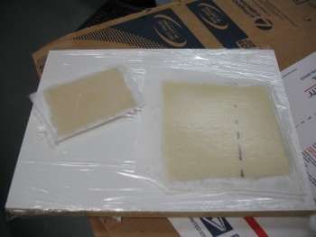
Today I cleaned up the layups on the headrest base piece and the GPS antenna shelf.

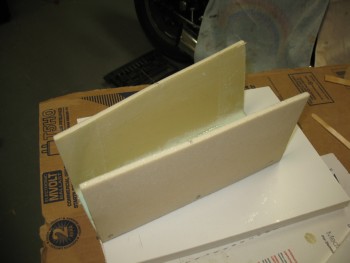
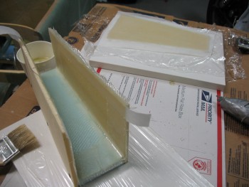
One issue I needed to address is that the front face of the headrest was a little off from straight vertically.  With the headrest on a flat surface, using a square I could clearly see that it was a few degrees less than 90°.  After a bit of head-scratching, I decided to simply add a few layers of BID to the front third of the headrest base, in a stepped fashion.

Base - Extra glass

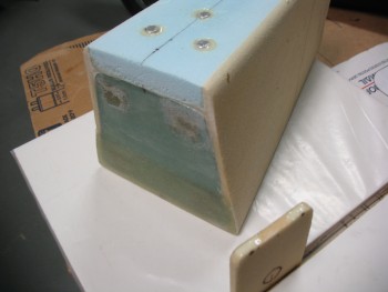
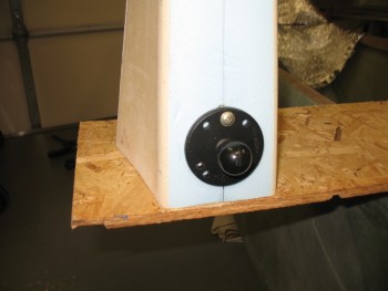
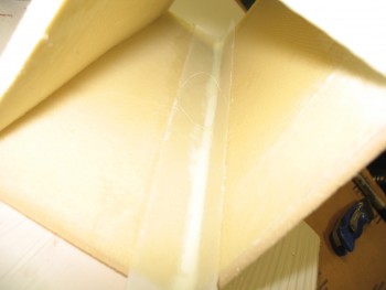
As far as the antenna shelf, I added hard points for the front screws, but the rear screws are actually located right on the edge of the antenna shelf insert that I just glassed.  So I Dremeled out the foam in about a .6 inch diameter half circle for each point where the rear screws go through.  I mixed some flox up and poured it into my prepared foam edge hard points.  Since I had extra flox leftover, I filled in the remaining gaps around each of the 3 threaded inserts for the RAM ball mount.  You can see this in the pic below:

Headrest Base & Antenna Shelf


Stay tuned, much more to come . . .

Chap 8 – More Headrest Stuff

Today I focused on tweaking the shape of the headrest tower to get it as close to symmetrical as possible.  Because of the design, it’d actually be somewhat difficult to see my slightly lopsided headrest assembly.  Nonetheless, I still wanted to get everything as balanced as I could.  I spent about an hour sanding the tower and was pretty darn happy with how the symmetry came out.

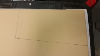
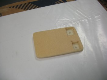
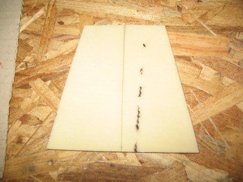
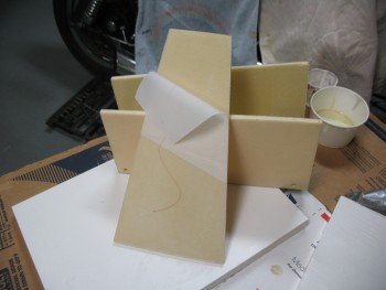
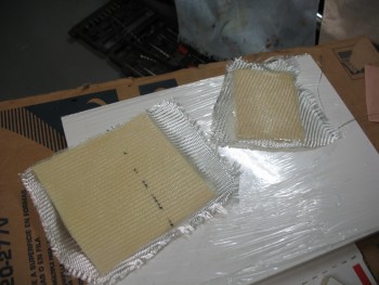
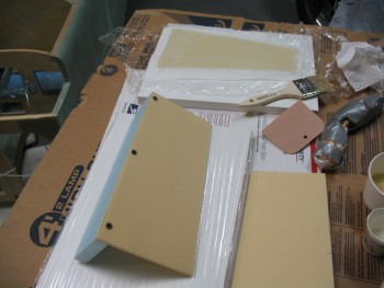
Headrest AssemblyWith the shape locked in, I worked on the GPS antenna puck shelf to install the hard-points that will keep the GPS antenna nice and secure.  As you can see in the picture below, I had 2 pieces of 1/4″ plywood marked off and cut the first one no problem, but when I cut the second one, it flew off into the bowels of the garage, not to be found no matter how much cussing and moving things around ensued.  Thus, I grabbed the next piece of plywood available, which was slightly smaller than the other one.  In my mind, here’s where NOT sweating the small stuff comes into play.  Thus, to save time, material and frustration, I simply embedded different sized–albeit capable–pieces of plywood for the hard-points.  I’m sure stuff like this drives the OCD’ers crazy, but that’s why I revel in not being OCD!

GPS Puck Mounting Shelf

My next task of the evening was to embed 3 threaded aluminum bungs into the back of the headrest to attach a RAM ball mount for the GIB.  I climbed into the back seat to get a good idea of what level the RAM ball mount should be attached.  Once I had that info in hand, I set about setting up the RAM mount to install the threaded aluminum bungs.

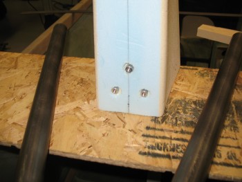
I started by cutting the 1 inch long aluminum threaded inserts (ala the Cozy Girrrls) in half since the foam is not thick enough to allow for the full length of a standard insert (aka “bung”).  After cutting them, I prepped the RAM ball mount by wrapping it with packing tape.  Once protected from the flox I would be using to hold the threaded aluminum inserts, I made 3 holes into the foam down to the opposite-side glass.  I then screwed the bungs to the RAM ball mount securely.  After mixing up some flox, I poured it into the 3 holes about halfway, then I embedded the 3 bungs attached to the RAM ball mount into the flox and let cure.  Below shows all this post cure.

RAM Ball Mount Inserts

And with the ball mount placed to show the final spacing.

RAM Ball Mount

Chap 8 – Headrest “box” finished

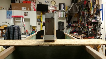
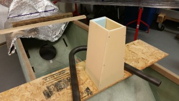
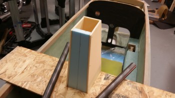
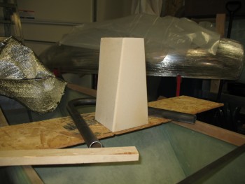
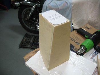
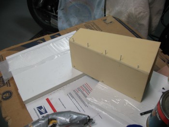
Today I took all the clamps off the cured headrest box.  I will state for the record that building a complex shaped box without the use of jigs may have quelled my inner artist, but it didn’t make for a perfectly shaped box.  Not bad, but the sweep (or swoosh!) on one side of the box from the front corner is slightly different than the other side.  A symptom of having glassed the front face to the rear part of the box one corner at a time.

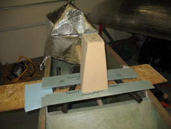
Anyway, I tweaked it with a myriad of clamps and will work on it just a bit more to massage the shape.  Regardless, here’s a couple shots of the completed headrest box structure.  Note that the top shelf insert for the GPS puck is just wedged into place and not glassed yet.  I will need to insert some small hard-points for the GPS puck screws to be fastened to.  In fact, in the second pic you can see the markups I did for the puck screw points & cable access hole.

Headrest "box" complete

Non-plans headrest tower

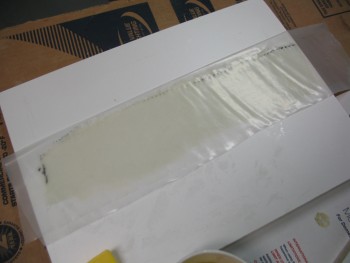
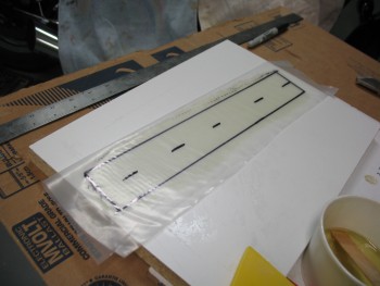
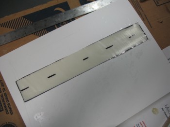
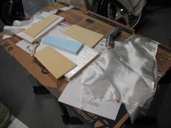
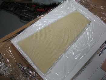
A couple of days ago I showed a pic of my glassing the foam for the GPS puck shelf and the headrest base, which I shaped to size below.

Headrest Base

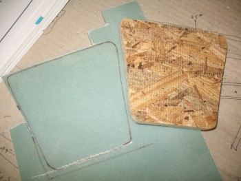
This headrest base–made of 1/4″ foam–would prove to a trooper that fought valiantly to stay in the game, but alas, it succumbed to the intense heat of my heat gun and warped as I was bending the headrest tower to my will.  As I hunted around for some more material, I ran across a scrap piece of 3/8″ Divinycell foam that was already glassed on one side.

Moreover, since I had ginned up a base mock-up out of OBS flooring board, I was already in the frame of mind for something just a tad thicker and robust than the 1/4″ foam base. After playing around with the shape for about half an hour, I transferred the actual wood base mock-up outline to the 3/8″ foam.

New headrest base

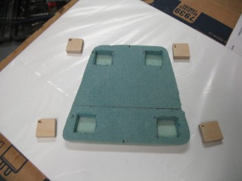
I then cut out some small square hard-points out of the Finnish Birch 1/4″ plywood that is used for the firewall, etc, after I decided where my headrest attach bolts will go.

Headrest Base Hardpoints

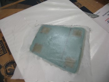
I floxed the plywood hardpoints into the holes that I made in the headrest base, and then covered each piece of plywood with about 12 plies of BID to fill up the remaining 1/8″ of space so that the hardpoints would be even with the face of the foam.  I then laid up 1 ply of BID over the entire piece of foam & peel plied it.

Glassed headrest base

I set the headrest base aside to cure overnight and called it a day.

I guess here would be a good point to digress & explain why I have bolt hard-points in the base of my headrest.  It all stems from the design of my 4130 steel rollover assembly, or simply the roll bar.  Since the main roll bar wraps around the back of the headrest tower, AND the front 1-3/4″ of the headrest tower actually sits on the rollover crossbar, there’s no way to hard glass the headrest to the base of the pilot’s seat and still have the rollbar removable (which is a design feature I would prefer to have)… since they’re interconnected.  A bolt-on headrest also allows for much easier future mods (if I decide to make any).  Or I can replace the whole thing with a super swank version later on if I so choose!


Chap 8 – Headrest build continues

Tonight I razor trimmed pieces, pulled peel ply & cleaned up the peel ply strings from the headrest layup.  After the layups cured, I was left with 2 assemblies: the front piece and the two sides/back wall as one unit.

Cured headrest - aftCured headrest - aft

Cured headrest piecesI then dry fitted front to right side wall assembly… doing one side at a time to minimize complexity.  I drilled holes for nails and preset those before glassing.

I then mixed up epoxy, micro’d the front wall piece to the right side wall piece, set with nails, cleaned up the exuding micro & then taped up the joint tight.

Headrest

I used fairly thick micro paste to fillet the corner, and then pre-pregged 1 Ply BID corner tape just a hair under 2″ wide so it would fit under 2″ peel ply tape.

Headrest corner pre-pregHeadrest corner pre-pregHeadrest corner pre-preg

After the corner was laid up I peel plied it with the 2″ wide tape.

Headrest corner tape

I also rough measured, cut & laid up two 1/4″ foam pieces with 1 ply BID for the headrest base and GPS antenna shelf.  I threw some peel ply on these last pieces and called it a night.

Headrest base & bulkheadHeadrest base & bulkhead


Chap 8 – Headrest Build

I started out today by picking out some good BID remnants for the layups on the interior surfaces of the headrest.

Chap 8 - Headrest Assembly

I then commenced to laying up 1 ply BID on the inside of the front face of the headrest. Since I’m not sure what all I’ll be glassing to it, I went ahead and peel plied the whole thing.

Chap 8 - Headrest Assembly

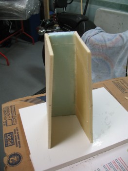
I had thought about just doing all the pieces separately and then assembling the headrest, but I thought since is my first real layup in almost 2 years, why not make it a little more challenging & interesting by laying up the 3 interior sides at once.  So I micro’d the 2 side pieces to the back piece and held them in place with wood screws.

Chap 8 - Headrest Assembly

I used micro paste to fillet the corners and then laid up 1 ply BID inside the resulting “U” channel.  After the glass was wetted out & looked good, I peel plied all the edges.

Chap 8 - Headrest Assembly

Step 1 of the headrest complete!

Chap 17 – Roll Trim Complete

Well, let’s say it’s 95% complete.  I still need to cut two 1/16″ 2024 aluminum “L” brackets to attach to the X-Tube (via the 3/16″ bolt) to then be attached to the aileron control tube with a stainless steel hose clamp on each aluminum “L” bracket.  I don’t have any 1/16″ angled aluminum on hand, so I’ll wait until I put in my next consolidated ACS order to pick some up (to save on shipping costs).

Nonetheless, here is my new, completed Roll Trim system:

Waiter's Roll Trim

Chap 8 – Headrest

Ok, I of course could have simply titled this “rollover assembly,” but the fact is I will have both: a rollover assembly for safety, which is essentially a 4130 steel roll bar, and also a headrest akin to the plan’s style headrest of years yore.  However, the distinct difference is that my headrest will be as minimal as possible and allow as much clearance for the GIB’s unabated view as possible.

Why a headrest?  There are 3 primary reasons I’m looking to incorporate a headrest into my rollover design scheme.  I would say that the following list is actually in reverse order of importance:

1) Obviously the name: headrest.  Not that I’ll be pulling so many excessive G’s so often that I’ll need a headrest, but I think it’s good to have one… especially when you need/want one.

2) Storage.  In a small plane like the Long-EZ, you need all the storage you can get.  Think of this headrest as a narrow tall box that is hinged at the top.  In it will go the many things required for preflight and ground ops like a fuel sampler, rags, tie-down lines, mini-chocks, flight control gust locks/pins, etc.

3) The Garmin GTN650 WAAS GPS stand.  If you’ve happened to have installed a Garmin GTN650 recently, or simply read the installation manual, you will have noted that to reach the appropriate resistance (1.5-6 ohms) on the coax cable connecting the GPS antenna to the GTN650 head unit requires a cable length of 6.5 feet.  Well, interestingly enough a cable run of 6.5 feet is spot on between the back of the GTN650 and the top of my headrest tower.  In addition, the farther away it is from any electrical devices, the better.

A week or so back I measured the distance between the top of the longerons and the inside top of the canopy in the general position that I’ll have the canopy.  With over 17″ of clearance for a rollbar, I figured I would go no higher than 15″, so I drew up a quick diagram noting all this.

Fast forward to this afternoon when I pulled out the Plans and discovered that Burt’s original triangular composite rollover assembly is 12.7 inches tall.  I took note of this since in order to save space, and maximize the view of the GIB, I really want to be in the general ballbark of the height of the plan’s rollover.  For safety I of course want it taller than my noggin, but only as tall as it has to be, no more.

With the plan’s rollover assembly dimensions in hand, I started designing my version of the headrest.  One set of dimensions that I knew right off the top was those for the WAAS GPS Antenna: approx 4-3/4″ x 3″.  This clearly is no compact antenna.

I had two simple overarching goals for the headrest:  shorter & narrower then the plan’s version.  I succeeded in meeting those goals …. sort of.  My headrest tower is definitely shorter, but the top is clearly bigger since there’s a robust GPS antenna living up there. The base is significantly narrower, and even tapers narrower moving aft.  With that being said, since I had 15″ of clearance, I started with an orginal height of 13-1/2″, about 3/4″ taller than the plan’s version.  Of course I suspected I would shorten the model, but I wanted to see how it looked… and it’s always easier to remove material than to add.

Here’s the initial cardboard mock-up of my headrest.
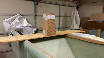
Headrest Mod

Headrest Mod

Without reference it looked rather tall.  I eventually whittled it down to about 11″, but then realized I needed to judge its height with it under canopy.  So I put the canopy over the 11-inch version if the headrest.
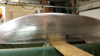
Headrest Mod

Moreover, I thought it might be a good idea that before I start glassing I should see how it relates TO MY HEAD.  Since it will be, in fact, a headrest.  The grand payback when incorporating any mod is of course time . . .  and pain.  So, using some simple risk management and avoid me toppling over inside the fuselage 3′ in the air, I needed to put it on the ground.  Thus, half an hour later I climbed inside to see how big my noggin really is! ha!
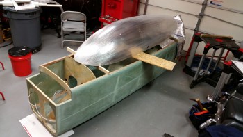
Headrest design

After messing about and playing the “I’m this tall” game with my hand against the top of my head going backwards (yes, I put the foam seat pad in place) I concluded that 11″ was just a tad too short [probably the perfect height would 12.7″… eh?!] and decided to add another 0.8″.  Thus, my final height for the headrest is 11.8″ tall (0.9″ shorter than stock, but wider at the top), and 5.8″ wide at the base (vs 8.4″ wide stock) and 5.8″ deep (vs 4.5″ deep stock).

To really get an idea of the height, I Googled some pictures of the Long-EZ’s rollover assembly and watched a few YouTube videos to get a good mental baseline picture before I went final with the dimensions.

Also, to check out the very general appearance of my aft-leaning rollover bar that will encircle the rear top edge of the headrest, I balanced the rollover bar on the headrest mock-up.
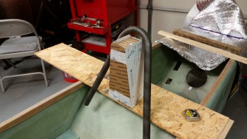
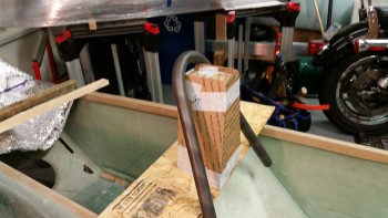
General fitGeneral Fit

Satisfied, I then started cutting out the foam for the headrest.  The front & sides will be 1/4″ thick foam while the rear will be 3/4″ foam, so that I can have much larger radiused corners at the back for a more “flowing” look:
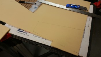
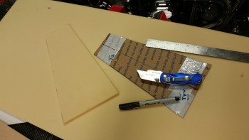
Headrest FoamHeadrest foamHeadrest Foam

And here’s how the foam pieces looked when I pinned all the bits together with small nails:
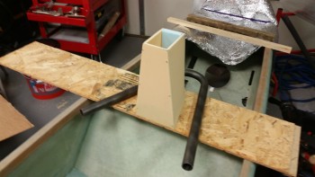
Headrest foam mock-upHeadrest foam mock-upHeadrest foam mock-up

And lest we not forgot one of the main reasons for this exercise:
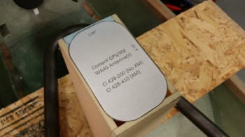
GTN650 WAAS GPS Antenna

A tight fit, yes, but I wanted to keep the top as narrow & small as possible.

I’m pretty happy with this headrest.  It will get the WAAS GPS antenna up where it needs to be, provide much needed storage and with the taper I have set I have a great view of the fuel site gauges and it it minimizes the view obstruction for the GIB.

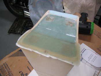


Chap 17 – Roll Trim Construction

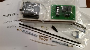
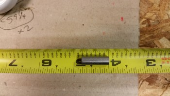
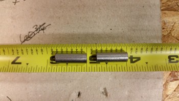
With all the parts assembled and on hand for the new Roll Trim System, I went to work making the ‘X’ tube (which is actually more akin to a plus sign +) that is created by welding two 3/4″ pieces of the 1/4″ dia 4130 steel tubing together. After welding (or soldering) these two pieces together, one tube will get a washer slid onto each end that is also welded/soldered into place.
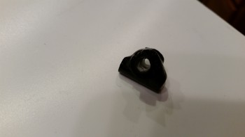
Waiter's Roll Trim System

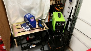
I went to work to finalize the setup of my TIG welding corner and dial in my TIG welder.

Welding Setup

After getting the welding station situated, I ran a number of beads to get back into the swing of things.  Although woefully still needing much more stick time on the TIG, I set about making the ‘X’ tube by knocking off the protective coating of the 4130 tube and then cutting the two 3/4″ pieces.

4130 1/4" dia tube4130 piece for "X" tube4130 pieces for "X" tube

I realized after blowing a couple of holes in the thin-walled tubing on my first attempt at making the X-Tube, that I had dialed in the wrong numbers on the TIG box.  Since I was using a 1/16″ Tungsten electrode, I had mistakenly dialed in the amperage for 1/16″ thick 4130 steel versus the correct amps required for 0.028″ walled tubing.  Another issue I had was that my filler rod was about twice the size I needed, so getting it to flow out without burning a hole in the thin tubing was a bit tricky.  Regardless, here was my first attempt at making the X-Tube:

Failed X-Tube

After dialing the amps way down on the TIG welder, I was able to eke out an X-Tube that would handily do the job.  X-Tube #2 was not pretty by any standards, but a quick brush up with the Dremel and some “Flocro” (Flox + Micro) using 4-year old MGS 335 proved to do the trick to make it presentable (see side note below).

Flocro'd Roll Trim X-Tube

Although not a beautiful specimen of welding, this little guy is strong!  I had re-read some of my notes on welding 4130 steel & it stated that 4130 is some tough stuff, and boy they weren’t kidding!  I had a slight bubble on the inside of one of the tubes that protruded about 60 thou (0.060″) into the tube.  No problem, I grabbed a cheap Harbor Freight 3/16″ drill bit to hone out the holes to ensure both tubes were clean.  That 60 thou 4130 slag bump chewed up the end of my bit like it was nothing!  I had to pull out my high-end drill bits to clean this sucker out.

Flocro'd X-Tube

I let the Flocro cure until is was just still soft enough to work.  I cleaned it up and then let it cure another couple of hours as I messed about with my headrest/rollover design.  After it had cured, I did one final clean up and then shot it with gloss black Rustoleum primer/paint.

X-Tube

I then set up a shop light about a foot away and let it dry.

Roll Trim X-TubeRoll Trim X-TubeRoll Trim X-Tube

After a few more hours I dry fitted the X-Tube onto the other components, and all fit well. I then left it alone to get in a good overnight cure.

OLD MGS 335 side note:
As I mentioned before, I was playing around with some old MGS 335 epoxy and hardener for a cosmetic makeover of the X-Tube.  When I say old, this is stuff that I had left with Marco back in the Summer of 2011 when I went to Germany.  The hardener had turned a puke brownish-green color and I had no idea what it would do.  But, my experience with MGS is that the stuff is magic, and since this was for purely cosmetic use without any structural expectations, I figured what the heck.  At first I thought the hardener was chemically dead, since after a couple of hours it was still pretty mushy.  But I left it in front of a heater, and lo & behold, a couple hours later it was hard as a rock.


Chap 17 – New Roll Trim

The magical truck that has all the airplane parts stopped by today to deliver an order from Wicks.  Since Wicks had a 10%-off special on all things composite for February I pulled the trigger on another gallon of West epoxy for the final finishing of this bird.  I also ordered something that I thought I had on-hand, but after my recent 100% inventory of EVERYTHING, I realized I didn’t: a piece of 1/4″ diameter x 0.028″ wall 4130 steel tube.

What is this used for you might astutely ask?  Why, my “new” roll trim system.

But first, you may remember that back in June 2013, my good friend, fellow Long-EZ builder, and MASTER machinist, Marco, made me the metal parts for my standard plan’s version roll trim.  From various Canardian PIREPs roll trim is not used a lot and I wanted to keep the plane as light as possible.  Then later, some other Canardians I spoke with talked about the inconvenient location of the plans positioned roll trim lever (read, at right-thigh seat level…not good for someone with more robust thighs!).  A few ingenious builders from the Old Guard had clever workarounds to make the roll trim more mechanically user-friendly… and much better ergonomically.

But after a fair amount of thought I came to the conclusion to strive for K-I-S-S.  I have a very nice, capable china-hat trim switch on a cool Infinity stick, so why not use it for both trims: pitch & roll.  Yes, it may mean literally a few extra ounces, so I’m doing the weight rationalization dance (kind of like ordering dessert after a big meal!), but the simplified operationally convenience will optimize cockpit management in my opinion.

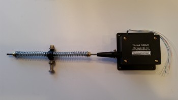
I looked at a myriad of different roll trim ideas out there, many using the “omega”-shaped composite spring (“Wright/Hanka Spring”) firewall aft, but I figured I would try out Waiter’s (aka John McAvoy) Roll Trim System as he describes on his site IFlyEZ.com.  Since nearly all plans for EZ Roll Trim systems revolve around the most expensive item involved: the Ray Allen RAC T2-10A servo, then I’m out literally $10 in parts if I want to switch to the Wright-Hanka style trim spring in case I don’t care for Waiter’s system.  A contributing reason for my choosing Waiter’s system is its location just aft of the pilot’s seat, in some real estate that isn’t being used for anything else.

Waiter's Long-EZ Roll TrimAlso, although this system is light (9.5 oz vs. plan’s roll trim of 4 oz), it still puts the weight of the components forward of the firewall rather than behind it.

With my decision made, I plan to knock this out in the next day or so.

Winter Wonderland

I thought I’d share some pictures I took on a quick jaunt up to Ridgely Field, MD (East of BWI and north of Easton, MD) out of my new home airport, Potomac Field, MD.

It was a rather cold day and VERY choppy below 3,000′.  I got banged up pretty good until I could finally get out from underneath all the Class B airspace in the DC FRZ & SFRA. Those heavy guys hog up all the airspace! (The guilty know who they are…) :)

Here are some pics I took as I headed back to Potomac on a south-westerly course across Eastern Bay (just southeast of the Chesapeake Bay Bridge that crosses from Annapolis to points east), across the Maryland shoreline on the Chesapeake.  In a lot of the shots you can see the small, distinctly-shaped Poplar Island, which is a great landmark when hopping across the Chesapeake.  As you can see, just about every bit of the water was frozen, making this flight look like an Antarctic adventure!

Hope you enjoy these!

Eastern Bay, MDEastern Bay, MD (N)Eastern Bay, MDChesapeake Bay Shore - MD (S)Eastern Bay, MD (NW)Eastern Shore - MDChesapeake Bay (S)MD Shoreline, Chesapeake Bay (S)Chesapeake Bay (SW)Eastern Bay, MDMD Shoreline, Chesapeake Bay (S)Eastern Shore - MDMouth of Eastern Bay - (N)MD Shoreline - Chesapeake Bay (S)Chesapeake Bay (L) Eastern Bay (R)Chesapeake/Eastern Bay (N)Poplar Island (L) Chesapeake Bay (S)Chesapeake Bay (N)Poplar Island, Chesapeake Bay (S)Potomac Airfield (KVKX), MD

And here she is, all snugly tied down and put away back home.

Cheers!