Consoles, Post-Cure & Gear

I started the day off focusing on the fuselage consoles.  I cleaned up the BID tapes I glassed last night on the consoles/armrests & removed the nails holding the console tops to the sides.

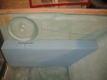
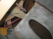
I notched the top of the left rear console (below) to prep it for an eventual install of a rear throttle quadrant.  Unfortunately, when I mocked it up I completely failed to take into account the ergonomics of where the throttle quadrant SHOULD BE positioned.  The positioning at the front of the arm rest is WAY too close to the GIB and needs to be much closer to the front seat.  No worries!  This is composites and I’ll simply fill that void in later!
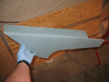
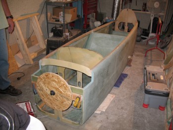
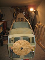
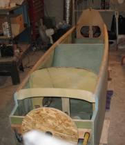
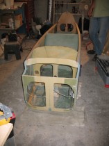
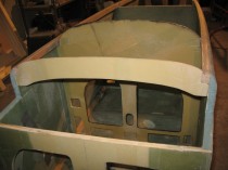
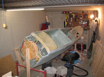
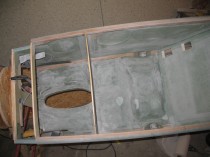
Chap 24 - Left Rear Console/ArmrestI then took the consoles out to the garage and mocked them up in the fuselage.  Again, since the fuselage side is curved and the console side edges are straight, I was just looking for the general look, fit & position of the consoles.  That being said, I did take some time to shape the outer edge of the front right console & carve the depression near where the control stick area mates to the side wall/control stick depression.  I then rounded over all the corner edges with a 3/8″ router bit.
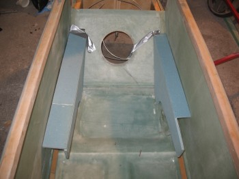
Chap 16/24 - L & R rear consolesChap 16 - Left Front ConsoleI cleaned up any left over/excess micro and errant strands of glass on the 3 consoles. I’m waiting to build the front Left console until I nail down the mounting configuration for my throttle quadrant.  The final tally on the consoles today is that the Right front & Left rear consoles are ready for exterior glass.

Now, the plans call for simply glassing 2 plies of BID over the entire exterior of the console and overlapping the layup onto the sidewall, fuselage floor, seats, etc. to secure it into place.  Since I won’t install these before they get shipped back to the States, I want to provide the foam with a little protection.  Thus, I’ll be glassing one ply of BID onto the exterior of the consoles, and then using a 2″ BID tape AND one more entire layer of BID to attach the consoles to the fuselage when I glass them in later on.  It will add just a bit more weight, but then I don’t have to worry about my foam getting all dinked up in the upcoming move back stateside.

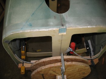
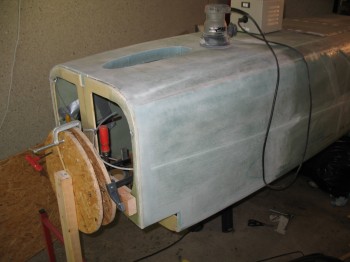
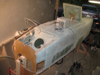
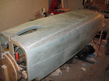
After I finished with the consoles for the day, I focused on the post cure prep for the fuselage.  I’ve spelled out the details and reasonings for the post cure in a separate post today.  My first task for the post cure effort was to make 2 stands that were capable of being adjusted on each corner in order to ensure that the fuselage is straight and remove any twist it may have.  I cut threaded rods into 4 pieces measuring 9.75″ each.  I used some 2x4s with holes drilled through each side and created a screwjack for each side of the 2×4, that will sit at the outside corners of the fuselage (sorry, no pics yet).

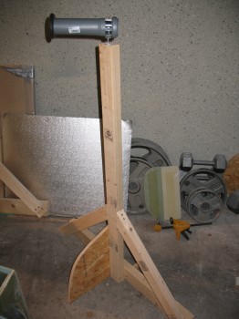
While I was at the DIY store I picked up a piece of PVC pipe to serve as my 3″ UNI tape roll dispenser for when I lay up the spar caps on the wings, CS spar and canard.  I retired the spit posts and pressed one of them into service as the new 3″ UNI tape dispenser.
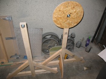
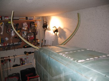
Retiring the spit posts!Chap 19 - 3" UNI Tape Roll "Dispenser"I then turned my focus back to the main gear.  I situated the fuselage back inverted and placed it on red stands.  I leveled the fuselage longitudinally & laterally using weights to hold it in place.  I then ensured the firewall was leveled vertically & clamped a 2×4 to it.  (I had previously marked the 5/8″ OD steel gear mounting tubes (LMGAT) 0.65″ from each edge, put wood jig tabs in place, and remounted them onto the fuselage-side main gear extrusions).  I put the gear in place and used an adjustable string setup to keep it upright and at the right distance from the firewall.  I taped a 6′ long carpenters level to the bottom of the each gear leg, centered front-to-back so as to minimize any error.  I set the gear with a 3/16″ gap between the top of the gear arch and the bottom of the fuselage longerons.
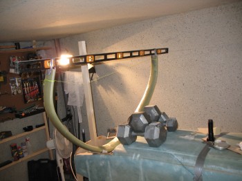
Chap 9 - Main Gear BuildI then set the axles’ centerline at F.S. 111.1 (stock plans is F.S. 110.5, but because I’ll be mounting a heavier IO-320 engine and some discrepancies I see in the plans, I’ll be moving the axle positions back about 1/2″ . . . [Ed. See my buddy Marco’s in-depth discussion on this at longezproject.blogspot.com… he explains it all nicely])
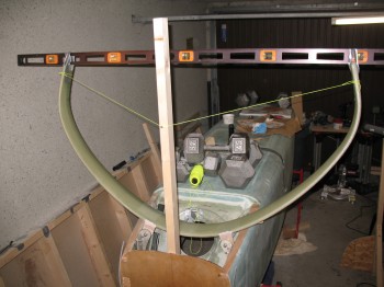
Chap 9 - Main Gear BuildAfter spending an hour or so ensuring that everything was lined up, straight, square… and that the measurements were as spot-on as possible, I bondo’d the wood jigs (that were pre-installed on the fuselage) to the main gear bow.
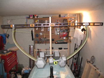
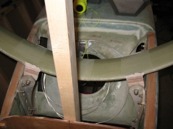
Chap 9 - Main Gear BuildChap 9 - Main Gear BuildAfter the bondo cured for a bit, I trimmed the excess off & cleaned it up, and then left it alone to dry overnight.
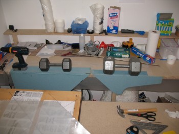
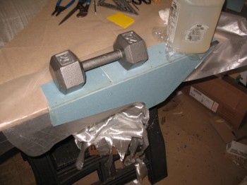
Done with Fuselage… for now

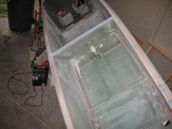
Today I knife cut the aft bottom fuselage layup at the front edge of the hell hole.  I removed the peel ply, sanded and cleaned it up a bit.

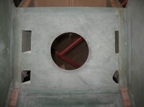
I put 1-ply of bid on the rear seat back and the rear seat pan (fuselage bottom) junction, and patched the errant hole mishap.

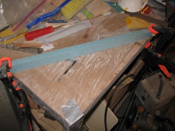
I turned my attention to the fuselage interior consoles (arm rests) and went to work on them in the downstairs shop.  On the Right front and the Left & Right rear seat consoles, I mounted the top to the sides with finish nails through the foam.  I then pre-pregged about a 1-1/2″ of strip of 1-ply BID and laid it up in the corner along the seam between the tops and the sides of the 3 respective consoles.  These will get more glass later when they get installed into the fuselage, so about a 3/4″-1″ overlap on each part will hold it fine.

I used straight fast hardener & let the consoles set for around 15 min, then I turned them right side up and set them on the side of the work bench, held in place with weights so that they would cure at the proper right 90°angle between top and sides.

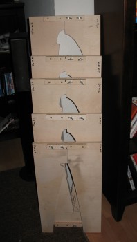
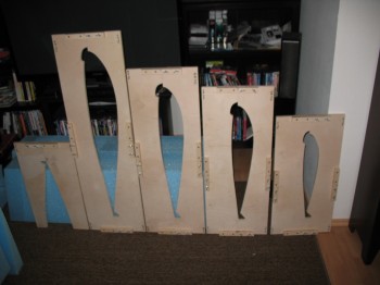
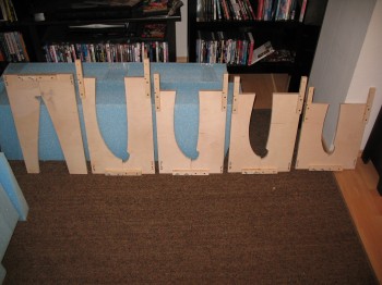
Chap 16 & 24 - Front R console & Rear L consoleChap 16 - Rigth Rear console/arm restWhile the consoles cured, I took the remaining Trailing Edge Wing Jig pieces to the wood shop on Ramstein AB.  I cut jigs #1-4 on the band, jig & table saws to produce their desired shapes.  I then took the jigs home & finished them by drilling the holes, sanding and installing bolts, etc.

Chap 19 - Wing jigs completedChapter 19 - Wing jigs ... completed!I then wiped down fuselage to remove all the fiberglass dust, took it off the spit and began taking a myriad of pictures.

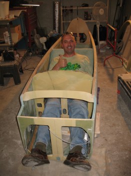
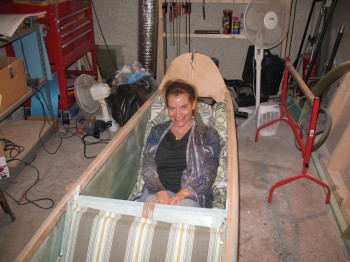
Completed fuselage"The Picture"The Help! :)


We call it: “Fuselage Centric” . . .

Today I started out by cutting & removing some excess glass at the bottom of the instrument panel.

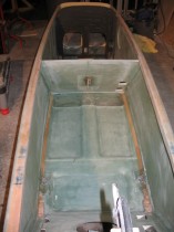
I then sanded all of the interior fuselage including sidewalls, front seat, back of instrument panel, floor pan, and front of rear seat.  I also knife scraped and sanded the inside, top and immediate exterior of the upper longerons.

Sanding Interior Fuselage (hard bank! :)

Sanding Interior FuselageI sanded smooth a micro repair on the rear seat pan [You may have noticed, and I failed to mention, that when I started cutting the channel for the brake lines I cut through to the inside of the rear seat pan about an inch long.  The reason why is because the left side of the seat pan has a smaller side shelf than does the right, and I was remiss in not taking this measurement into account and was using the measurement for the left side shelf.  You can see the errant cut in the second pic below].

I decided since I was going to have some type of removable hell hole cover (Yes, let the debate over that rage on as well!) that I would clean up & shape the very back edge of the fuselage bottom.  This would also allow me to secure the first few inches of the brake lines.

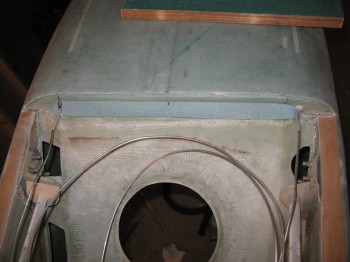
So I devised a plan, and cut a triangular wedge of blue foam to build a mini ramp on the back of the fuselage bottom foam, right where it meets the bottom aft part of the rear seat.  I of course turned the fuselage back upside down to work on this.

Rear seat/aft end fuselage bottom fillRear seat/aft end fuselage bottom fillRear seat/aft end fuselage bottom fillI micro’d in the foam wedge & all the foam surfaces and laid up 2-plies of BID over the entire lower aft fuselage and aft rear seat junction.  I also covered the brake lines with dry micro and the BID plies.  To ensure it stayed in place I used some duct tape and peel plied it as well.

Rear seat/aft end fuselage bottom glass

Fuselage cleanup

Today was all about cleaning up the fuselage.  Since I cut F22 to the original specs, and the fuselage bottom foam changed in thickness from the original 1.6″ to the currently supplied 1.75″, I have an overhang of 0.15″ (1/8″+) of foam dropping below the edge of the bottom of F22 (oops!).  I’ll deal with that later when I build the nose.  For now, I removed and cleaned up the overhanging glass from when I skinned the fuselage.

Sanding fuselageSanding fuselageI then proceeded to give the external fuselage a light sanding to knock down whatever excess epoxy was left from the fuselage skinning.  The pictures make it look like the glass completely changes color, but most of the color change is from the fiberglass dust.

I also sanded down the landing brake areas including the leftover bondo from the “speed brake flap” construction and the interior fuselage side of the assembly.

Sanding fuselageSanding fuselageSanding fuselageI Dremeled away dead glass overlapping onto the firewall and knife cut & sanded in the landing gear and hellhole area.  I also removed, via Dremel, dead glass from the left lower rear seat area where it overlapped just aft of the fuselage bottom (on the hellhole side).  I then sanded the aft side of the rear seat.  I did a bit of Dremel-work in the area to knock out any dead glass as well.

Sanding fuselageSanding fuselageSanding fuselageOf course I didn’t sand any of the sidewall areas that would eventually get cut out for strake access.

Sanding fuselage


Getting organized (& gear mocking!)

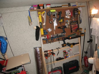
Today was all about FINALLY getting some of the items organized in the shop.  I built a tool organizer against the back wall replete with peg board & then organized all my tools.

Organizing the shop!After my tools were organized, I went downstairs and took the gear off of the jig and removed all the peel ply from the gear.  I then tore the jig down.

Well, with the main glassing done on the gear I had to see how the gear looked mounted.  So I took the gear out to the shop and spent a fair amount of time messing about and mocking it up.

IMG_0002

Chap 9 - Mocking up main gear install

Chap 9 – Glassing main gear (& building wing jigs)

Today I planned out & ordered some RG-58 coax cable as per Jim Weir’s instructions for constructing antennas for EZs.

I also planned out some glass cuts for my Über-talented & lovely assistant, Gina, who excels in the arts of epoxy-mixing & glass-cutting.  She cut BID and UNI scraps for the main landing gear mount brackets while I worked on the wing jigs.  I cut out the #5 jig and the front sides of jigs #1-4.

Chap 19 - Wing JigsOnce the jigs were cut out, I mounted the 1″ x 8″ brackets on the jigs with glue & wood screws.  I drilled the two 1/4″ holes for the mounting bolts & wing-nuts but since I was using 3/4″ plywood instead of the planned  1/2″, I had to also countersink the bolt heads.

Chap 19 - Wing JigsChap 19 - Wing JigsI finished sanding the main landing gear bow in preparation for glassing the last of UNI layups on the gear legs.

Chap 9 - Main gear ready for final glassI set up the downstairs shop to glass the landing gear:  I cut the plastic for the UNI pre-preg set-ups and 5-min epoxied the gear to the 3 drywall screws.

Chap 9 - Main Gear final glassChap 9 - Main Gear final glassI then laid up the final sets of UNI.

Chap 9 - Main Gear final glassChap 9 - Main Gear final glassChap 9 - Main Gear final glassChap 9 - Main Gear final glassWhen all was finished, I had laid up 4 alternating layers on both the left and right sides of the gear bow, wrapping around the leading edge and coming together on the trailing edge.  Remember, each of the 4 layers of UNI alternate 30-40°, with two layers going in one direction and the other two layers going in the other direction to create a cross-hatch.

Chapter 19 – Wing jigs & foam cores

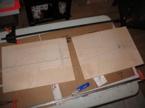
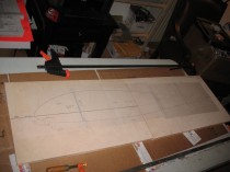
Today I glued the paper wing jig templates to the cut 3/4″ plywood wing jigs.  It took a while to find the trailing edge tip for one of the templates, but I finally found it.

Chapter 19 - Wing jigsChapter 19 - Wing jigs

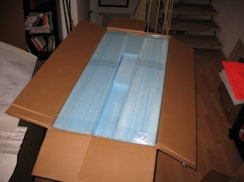
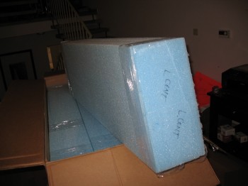
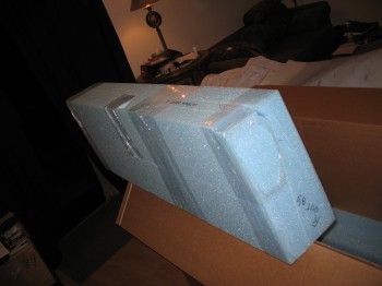
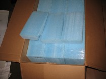
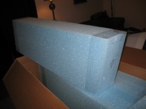
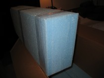
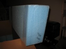
After I got the paper templates glued on (I used 3M 77 spray glue) and cleared the jigs and table out of the way, I pulled out the huge Feather Lite crate that contained my foam cores and began to unpack it and inventory the foam wing cores.  As I stated a few days ago, I had been reviewing the plans since to get a decent idea of what I was looking at.  It still took some time to figure them all out.

Chapter 19 - Wing foam core inventoryChapter 19 - Wing foam core inventoryChapter 19 - Wing foam core inventoryThe Prime Directive during this specific task: DON’T DAMAGE THE FOAM CORES!!!

After I inventoried all the wing core pieces, it looked as though I was NOT going to need a hotwire saw to build the wings with what I had here.  Remember, I left my hot wire saw in Virginia with my buddy Marco.

Wing Jigs, Landing Gear Jigs & Completed Landing Brake!

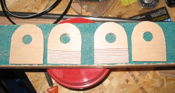
I spent about 2-1/2 hours at the wood shop on Ramstein today.  Not nearly as bad as last time… I cut 4 each Main Landing Gear Mount jigs with 5/8″ holes and tapered edges.  These will be used to temporarily “mount” the gear to the fuselage gear mounts with bondo and then also serve as the form to create the gear tabs that will eventually hold the gear to the fuselage.

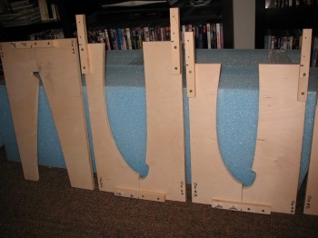
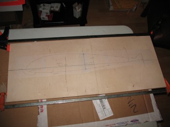
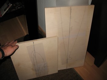
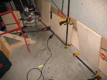
Chap 9 - Main Landing Gear JigsI then cut out all the wing jig segments from 3/4″ plywood (the plans call for 1/2″ plywood but their’s was REALLY warped, so I went with nearly the only plywood left in Germany: 3/4″).  I then cut 17 each 1″ x 8″ connector pieces that will eventually get mounted to each segment of the jig.  In building the jigs, I’m making every attempt to get the wing jig outline to match exactly per the outline of the paper template.  To do this, I’ve taken into account the blade kerf width on each saw I use.

Back at the shop, I glued all the forward pieces of the jigs together and clamped them.

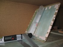
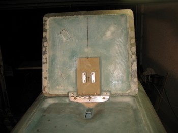
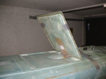
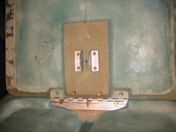
Chapter 19 - Wing JigsChapter 19 - Wing jigsAs for the landing brake, I extended the landing brake actuator hole aft by about 3/16″.  I then readjusted the topside metal mounting bracket–on the rear side of the front seat–up by 1/8″.  This locked in the landing brake door/flap opening angle to 59.6°.

Section VI - Landing Brake

And here’s a look at this guy in action!

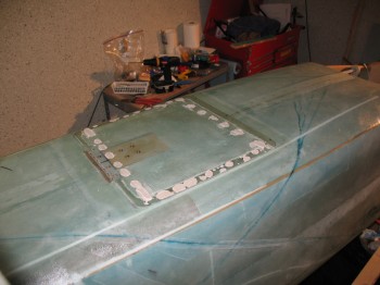
Although there is some finishing steps that need to be completed to form the edge of the landing brake even with the fuselage, I am declaring Section VI complete!

After I finished messing about with the landing brake, I turned my attention back to the main landing gear.  I spent over an hour and half sanding and prepping it for it’s final glassing.


Section VI – Landing Brake

Today was all about the landing brake.

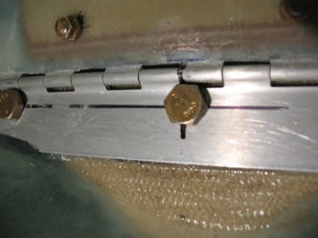
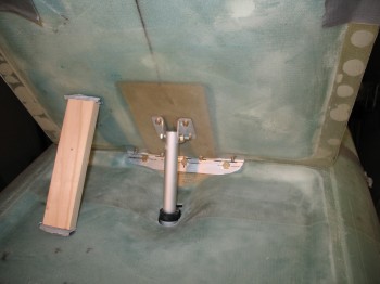
I had to grind out a divot immediately above the middle bolt that attaches the landing brake hinge (LB24) to the fuselage (LB23) since the bolt head was keeping the landing brake from closing all the way.  This goes back to my earlier statement that even though the bolt holes were drilled at the centerline dimension-wise of the hinge, when the hinge is angled back the way it is, it moves the bolt line up.  This was the cause behind the middle bolt hitting the landing brake.  However, a little improvisation took care of the issue.

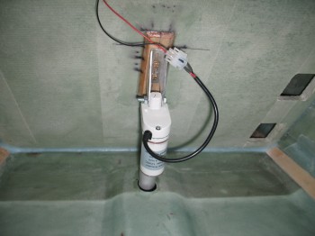
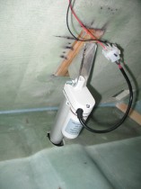
Section VI - Landing BrakeAfter I got the hinge closing issue resolved, I made up a template of the electric actuator body and then mocked up the landing brake actuator.  As I was extending the actuator in and out I noticed the end of it, where it attaches to the landing brake bracket (LB18), was twisted just a bit so that all the bolt holes would not align.  That took me offline for a bit as I had to figure out how to get the bolt hole on the end of the actuator arm straight again.  I attempted to call the manufacturer but couldn’t get a hold of them.  I tried Jack, but no joy. I then looked at the exploded view in the PDF online.  As I methodically & slowly took the actuator apart, I realized that the actuator arm tip could be turned hard against a phenolic plate.  That fixed it!

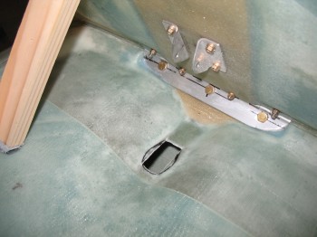
I cut the actuator hole in the fuselage a little wider & longer and shaped it to the outline of the main actuator body (not just the arm) since the entire actuator had to be able to get thru the hole.

Section VI - Landing BrakeSection VI - Landing BrakeSection VI - Landing BrakeAfter I got the actuator hole squared away, I spent a fair amount of time mocking up the actuator angle, position and the opening/closing of the landing brake door.

Section VI - Landing BrakeSection VI - Landing Brake

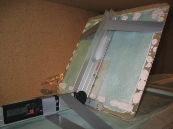
After figuring out the proper location of the seat back landing brake actuator mount, I cut & drilled the holes in the front seat back.

Section VI - Landing BrakeI micro’d the holes & floxed on the mounting bracket.  I pre-pregged a 2-ply BID layup measuring 3.8″ x 8.3″ and glassed the bracket onto the rear of the front seat back.  I then peel plied it and weighed it down.

Section VI - Landing Brake


Section VI – Landing Brake… & console stuff

I permanentaly installed the landing brake/landing brake hinge with flox.  I bent the hinge pin as per CP 30 so it looked like a wavy piece of wire.

The flox squeezed out from under the hinge plate into the hinge itself, so I had to keep working it back and forth to to get all the excess flox out.

Also, before mounting, I constructed a 0.5 mm anodized aluminum shim for the middle hinge bolt hole area to keep the hinge straight.
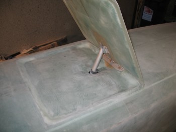
Section VI - Landing Brake

Section VI - Landing Brake

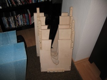
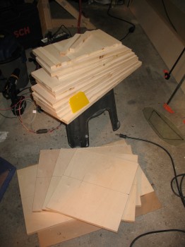
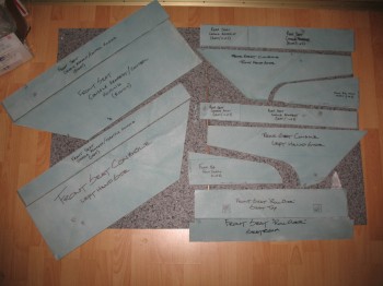
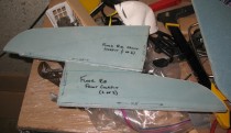
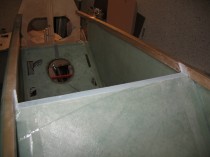
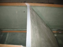
I gathered up all the individual parts of the Chapter 16 and 24 consoles, arm rests & front seat ribs for some pics, as shown below:

Chapter 16 & 24 - Side consoles & Armrests

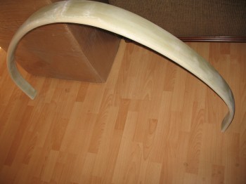
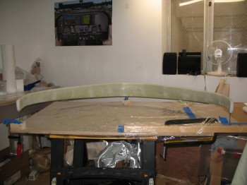
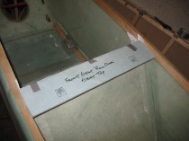
I also grabbed a few more pics of the Chapter 8 top of the front seat back.