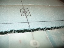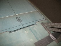
Section VI – Landing brake hinge nutplate & stuff

Well, being a noob I decided NOT to use the 0.5mm anodized aluminum and went with 0.063″ 2024T3 aluminum instead as a plate to secure the nutplates behind the LB23 hard point.  I wasn’t sure if the .5mm aluminum was robust enough for the task and the time difference wasn’t favorably to using my “call a friend” option, so I accepted the extra ounce of weight and pressed on.

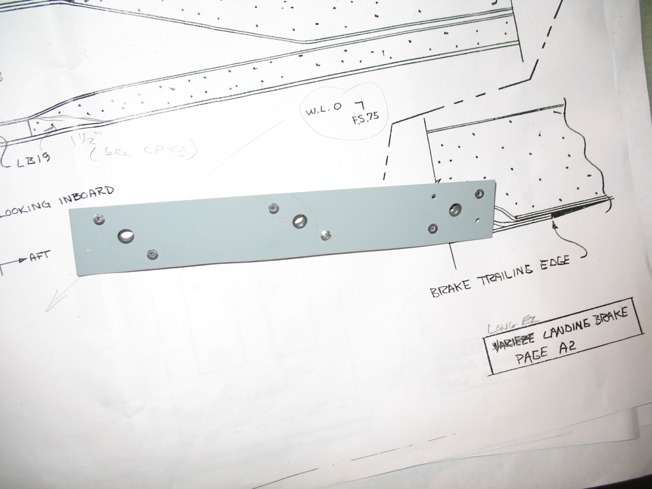
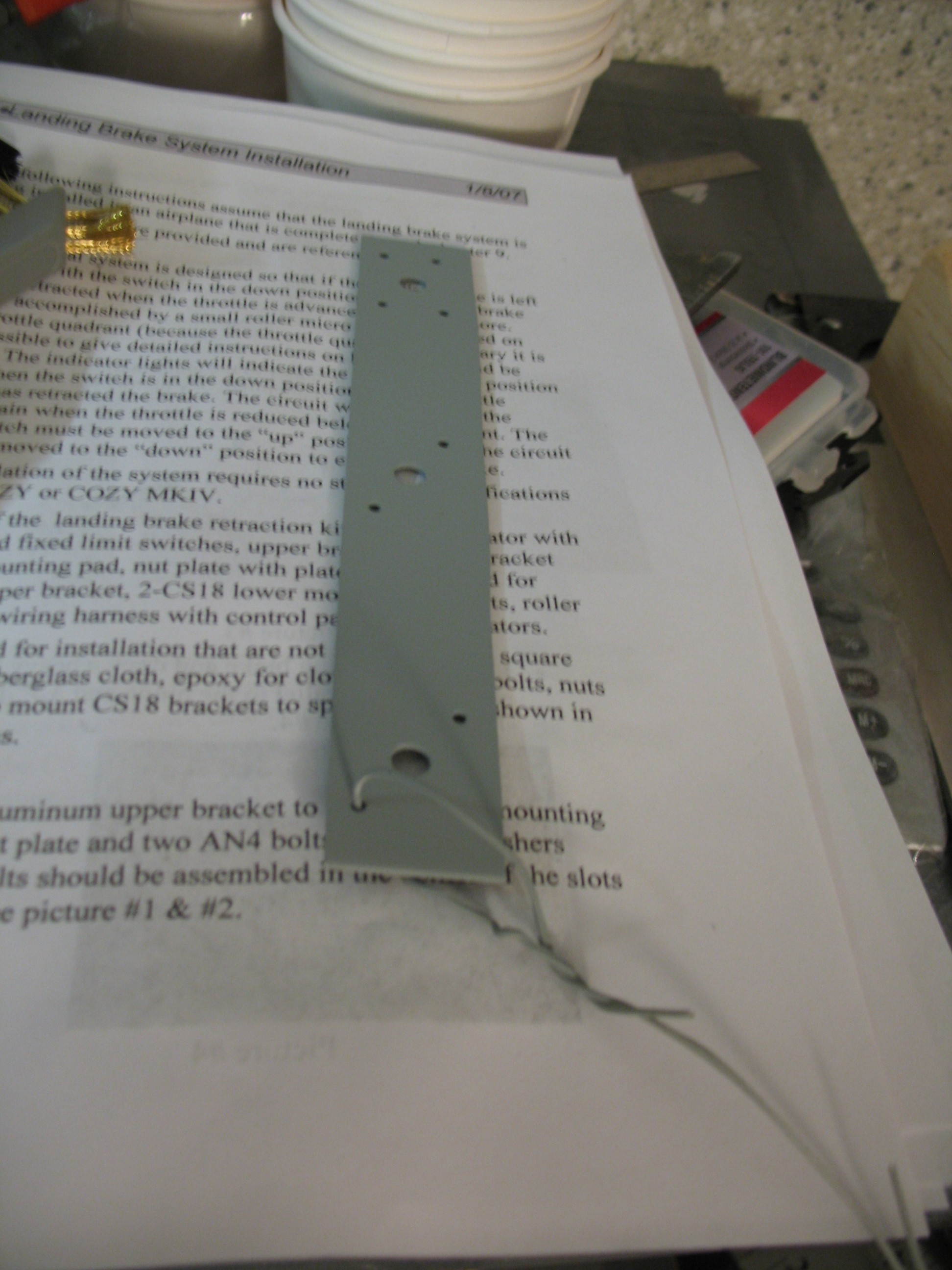
I cut the aluminum into a 1.1″ x 8.0″ piece, marked the 1/4″ bolt holes and the 1/8″ rivet hole positions for the K1000-4 nutplates.  I drilled the 6 ea 1/8″ holes first then I drilled the 3 ea 1/4″ holes.  On one end the 1/8″ rivet holes didn’t line up just right, so I flipped the nut plate on the opposite angle and re-drilled.
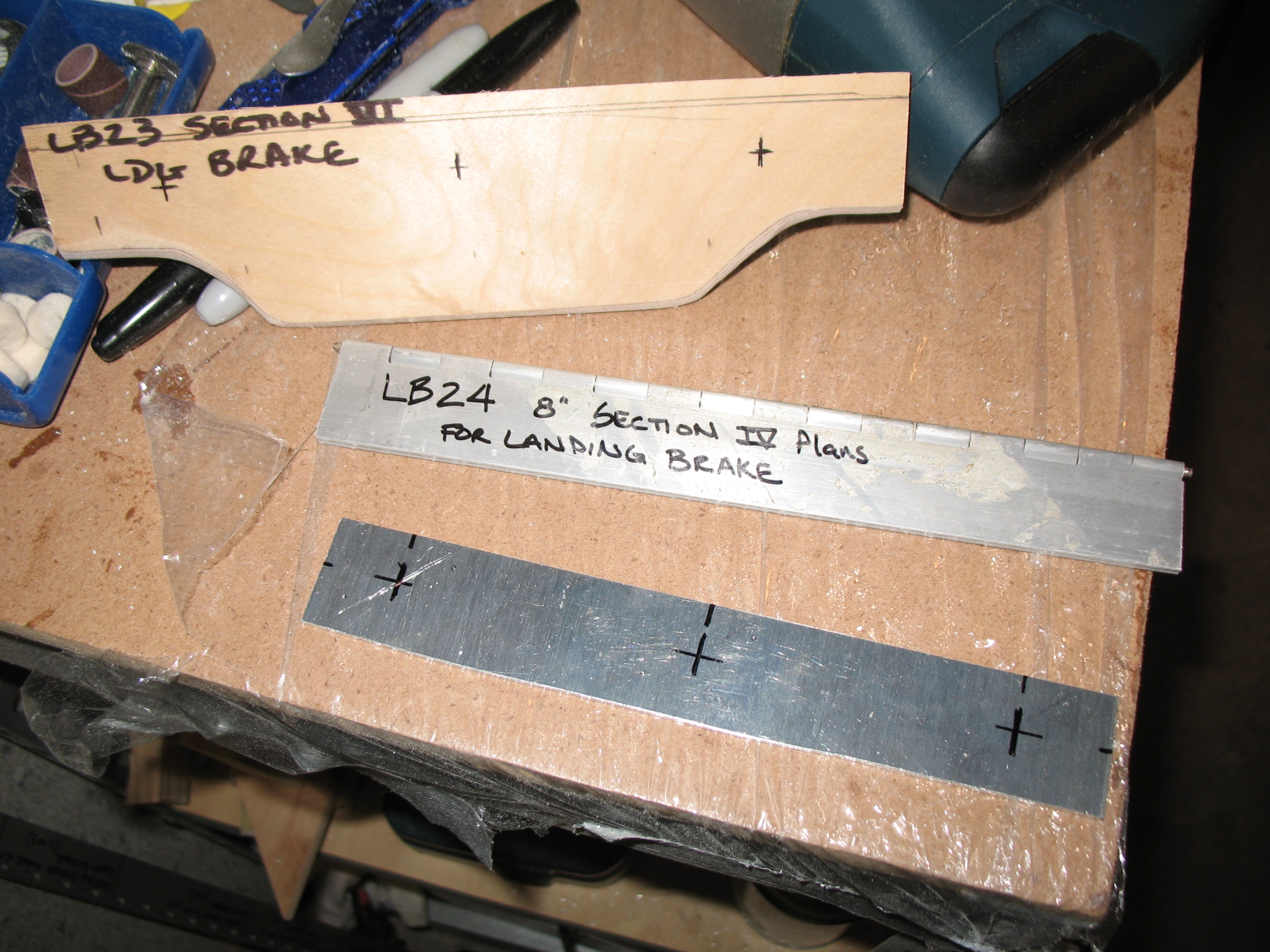
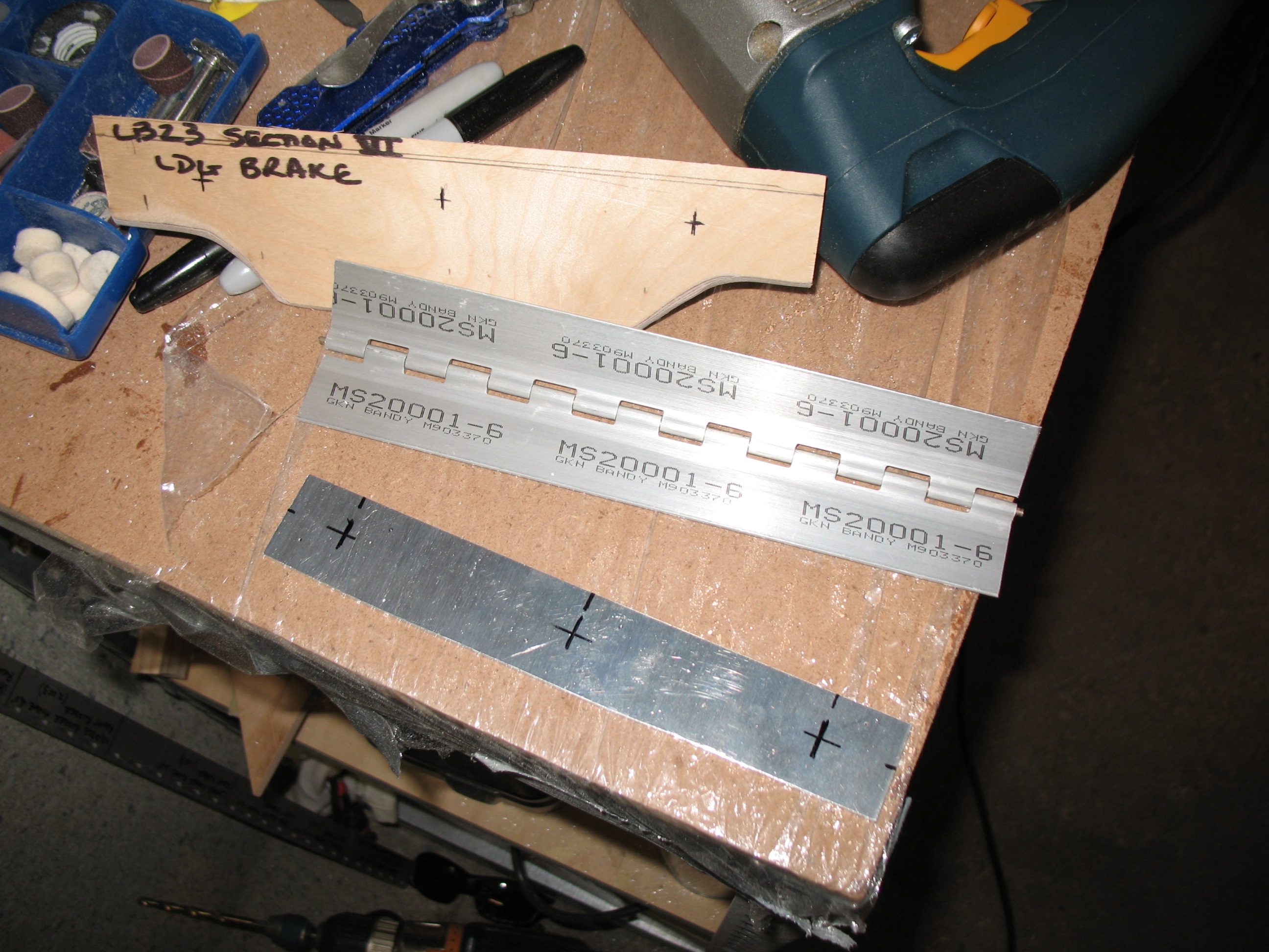
Section VI - Landing BrakeSection VI - Landing BrakeI chamfered all the holes and then prepped the aluminum plate for primer by washing it with simple green (amazing stuff) and 60 grit 3M pads.  Once it was dry, I hung it on a wire and rattle-can primed it with Rustoleum. [You may be asking why I didn’t Alodine the 2024T3?  Well, I was trying to.  I had alodine and alum-prep… IN THE STATES!  Which of course I couldn’t ship over to Germany.  And as hard as I tried (via Aircraft Spruce.EU… great folks!) I could only get aluma-prep, but not Alodine.  I tried everything I could think of, but try a Google search in German!  I did however eventually get the Alodine as well.]

Section VI - Landing Brake

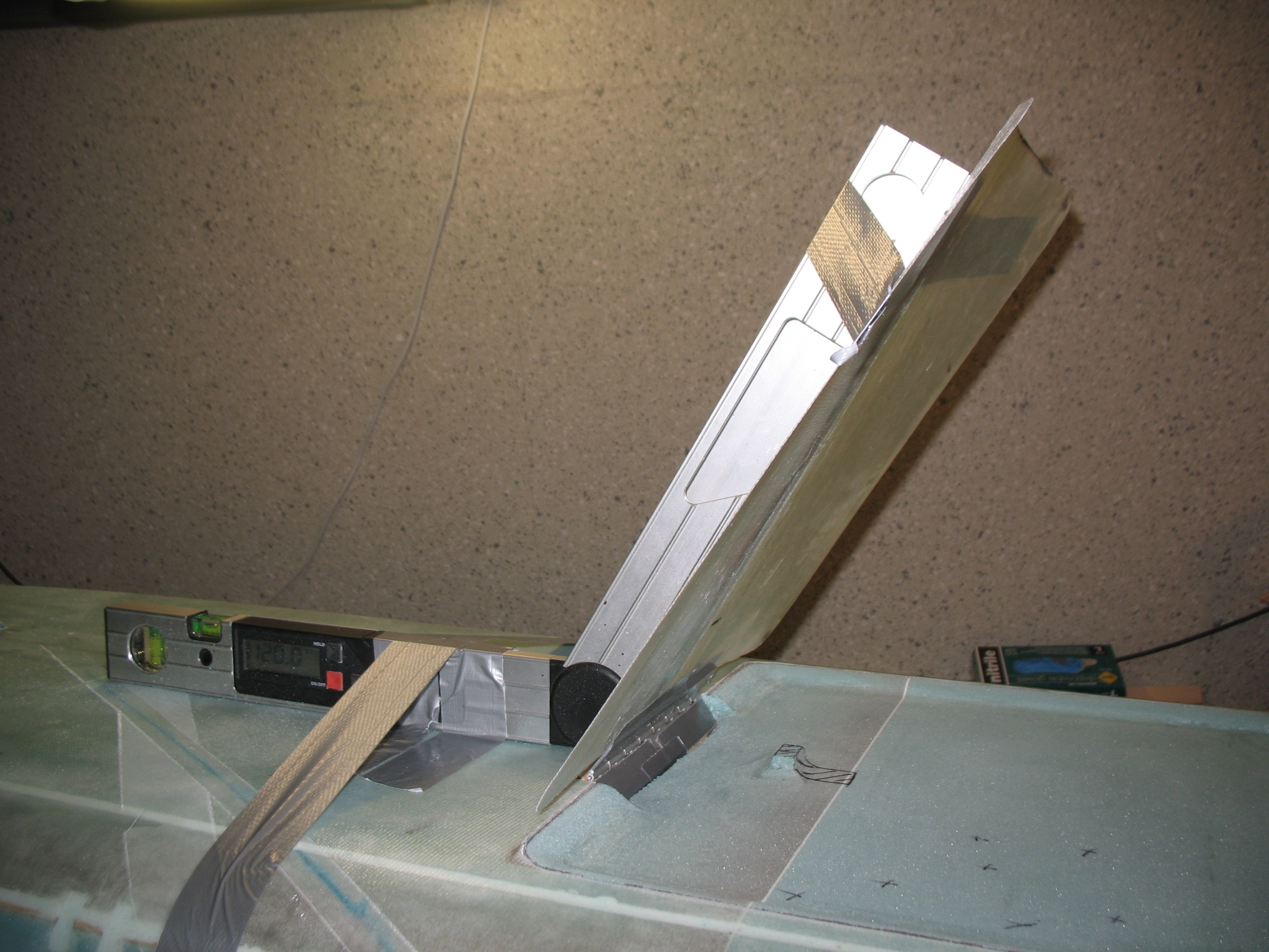
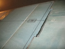
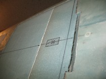
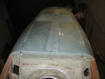
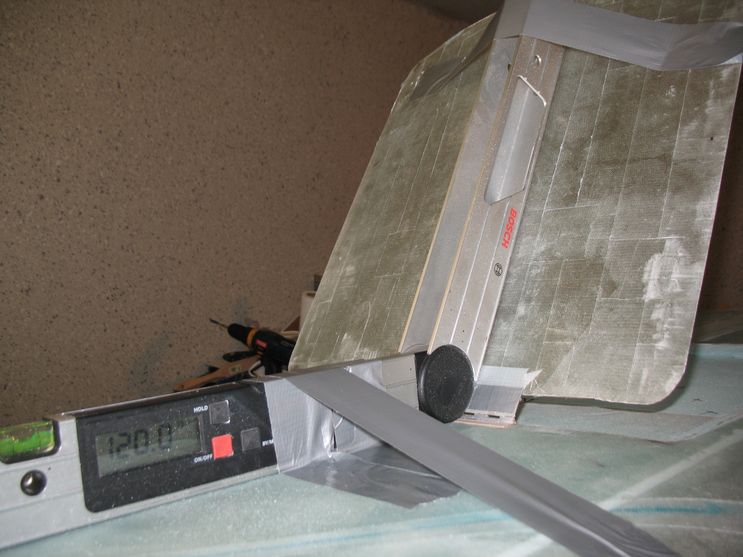
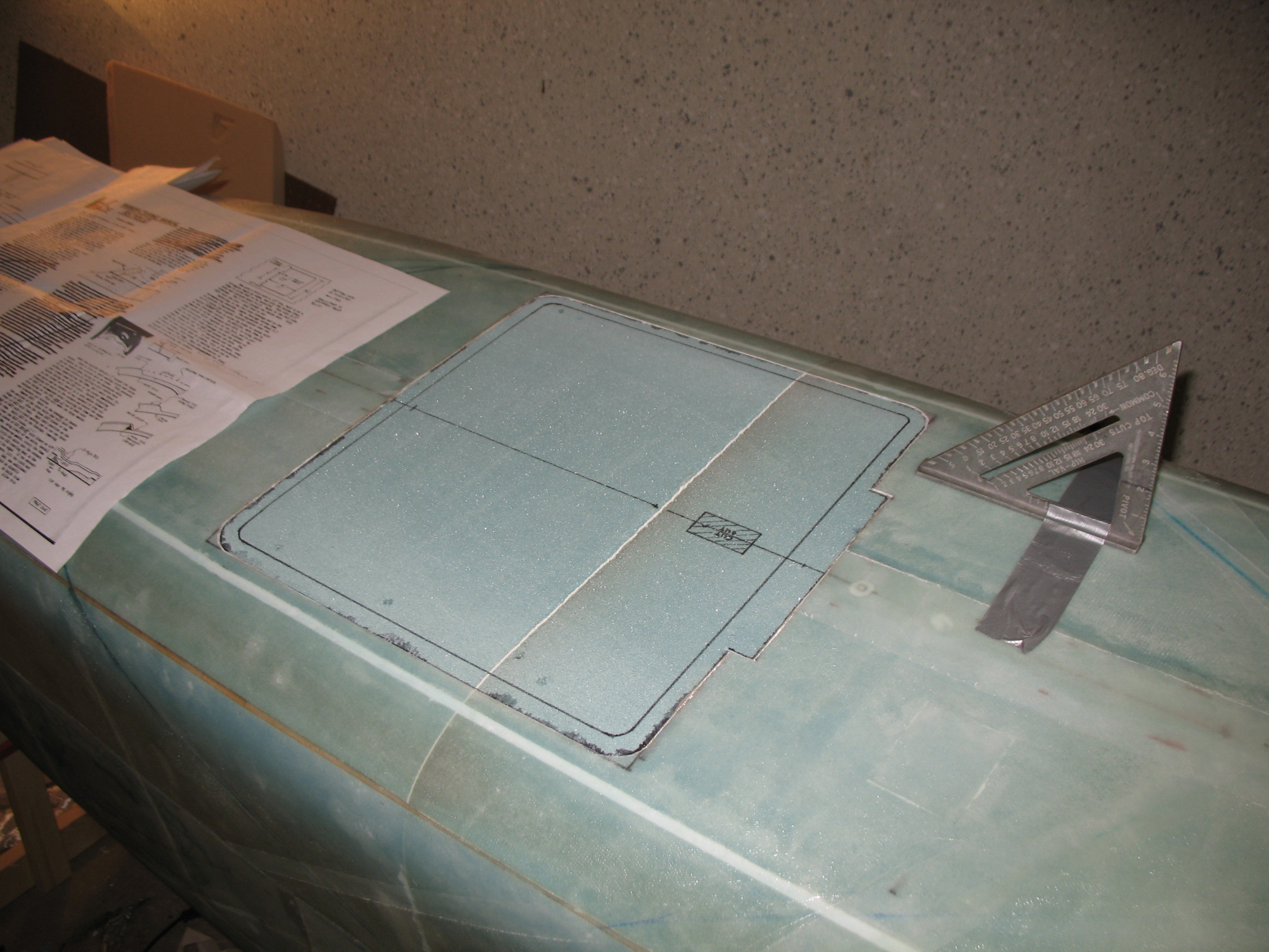
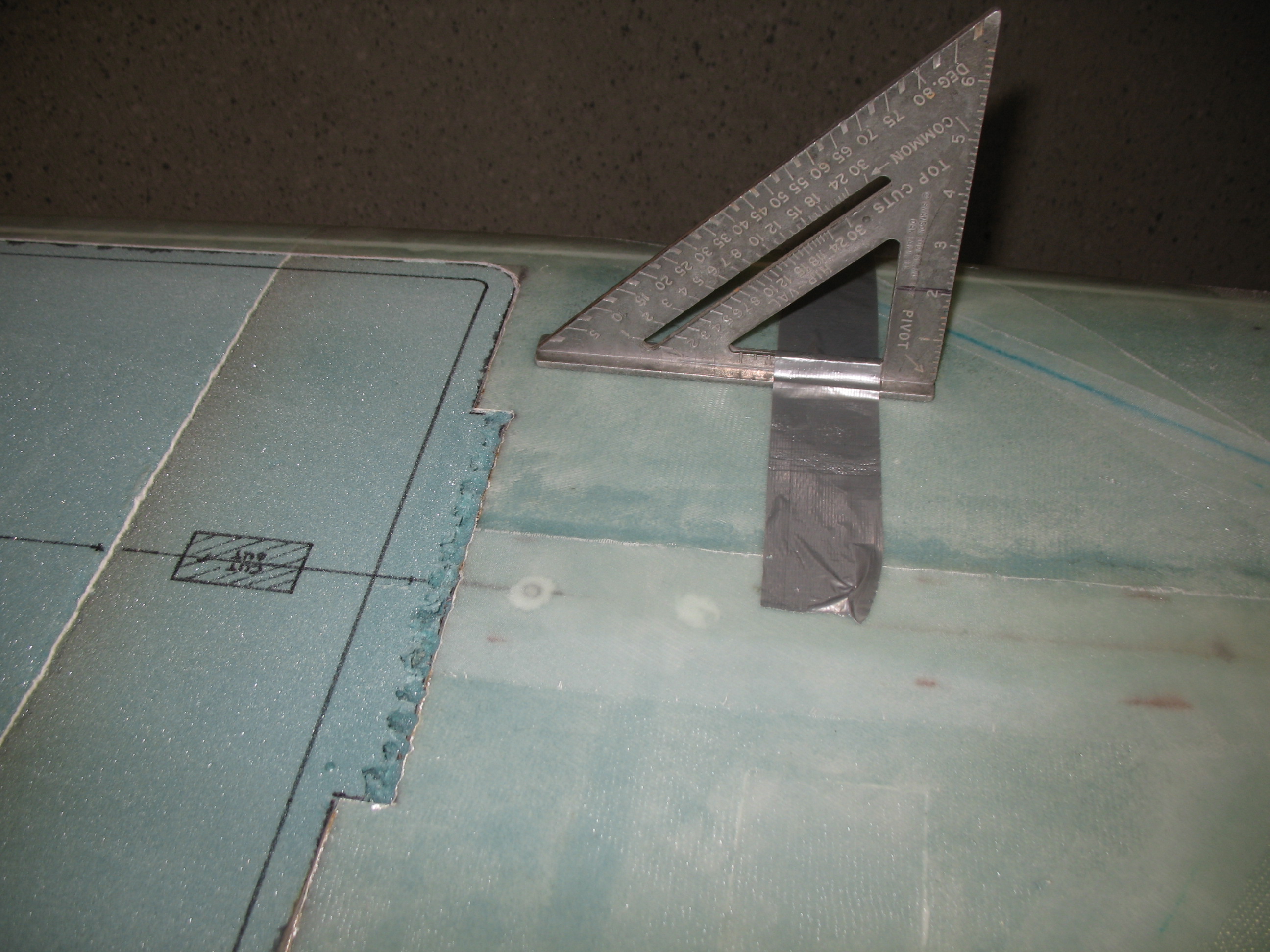
While the primer dried I mocked up LB23 and temporarily attached the hinge using duct tape.  I used the landing brake fuselage glass  outline, that I removed initially, as the landing brake door.  I set it at the required 60° angle (the digital square shows 120°, since to get 60° you have to subtract it from 180°:  180 – 60 = 120).  Now that was EZ!
Section VI - Landing BrakeSection VI - Landing Brake

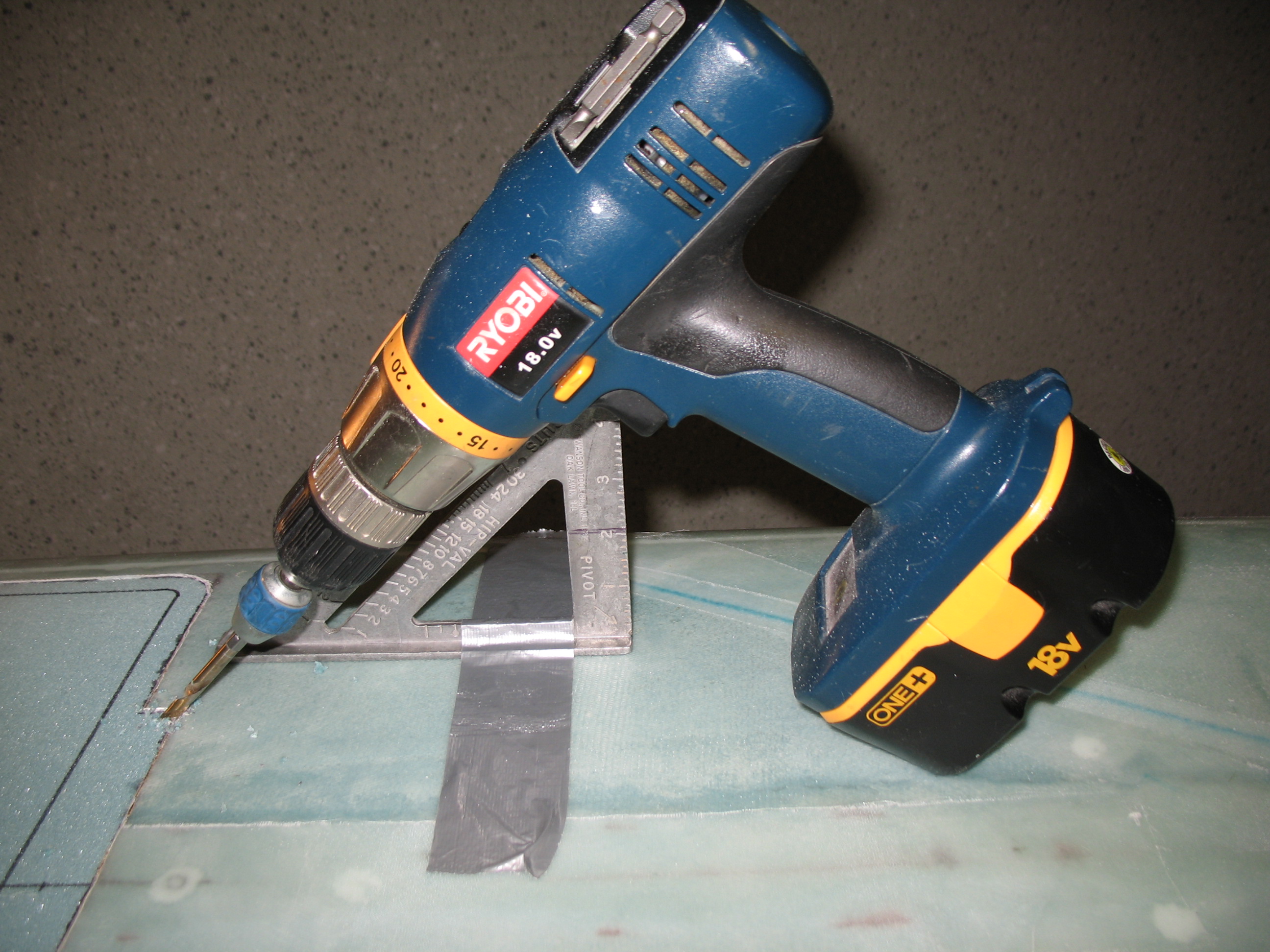
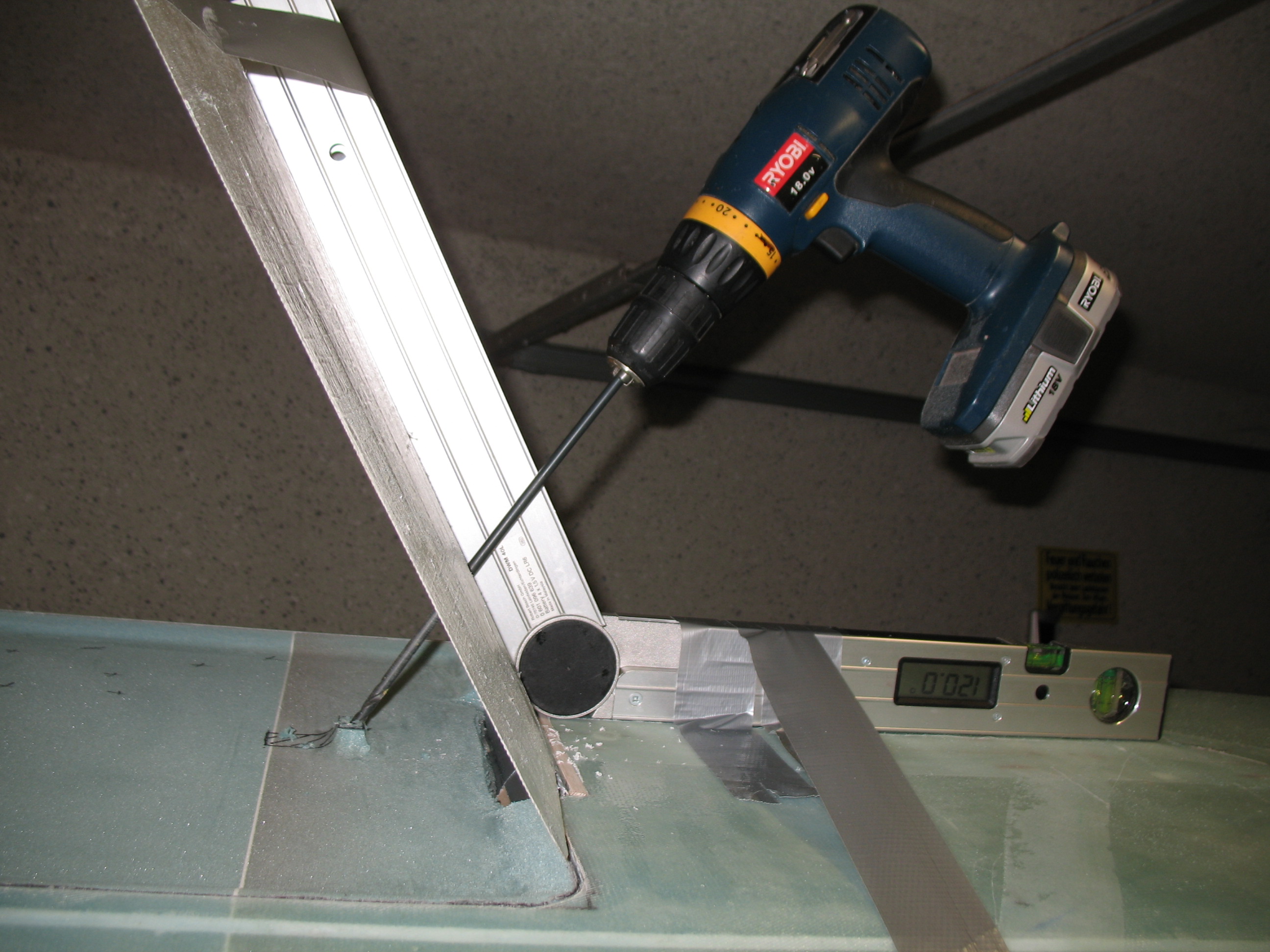
Since I’m using Jack Wilhelmson’s Landing Brake Actuator, I used the measurements out of his included instructions.  I drilled through the “landing brake door” at the 3.7″-from-hinge position down through the bottom of the fuselage.
Section VI - Landing Brake

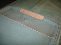
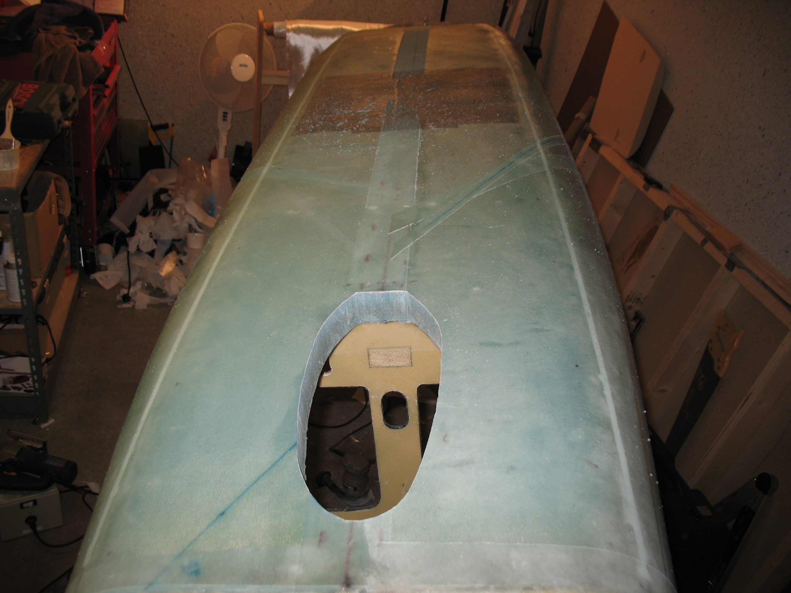
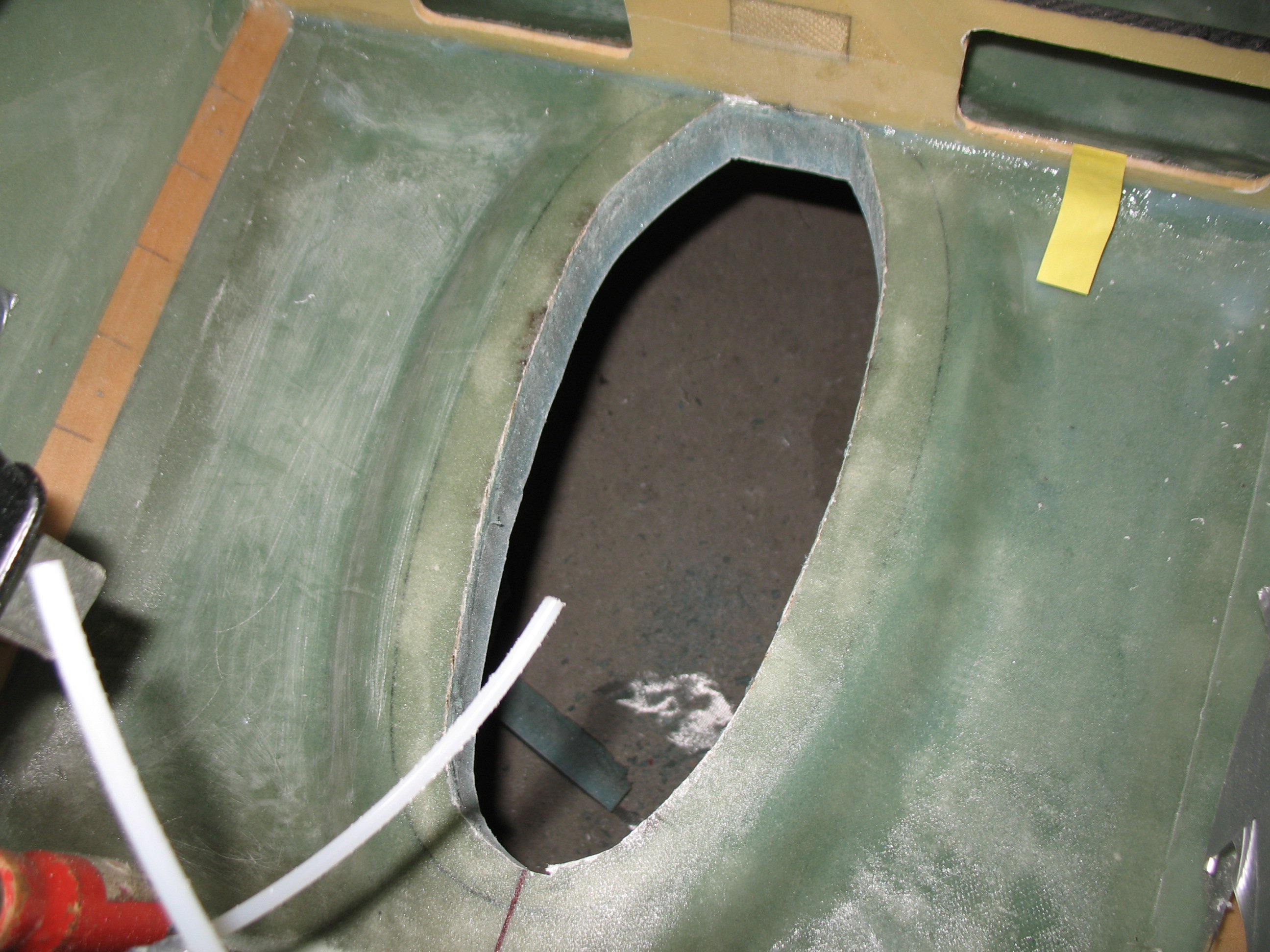
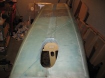
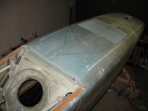
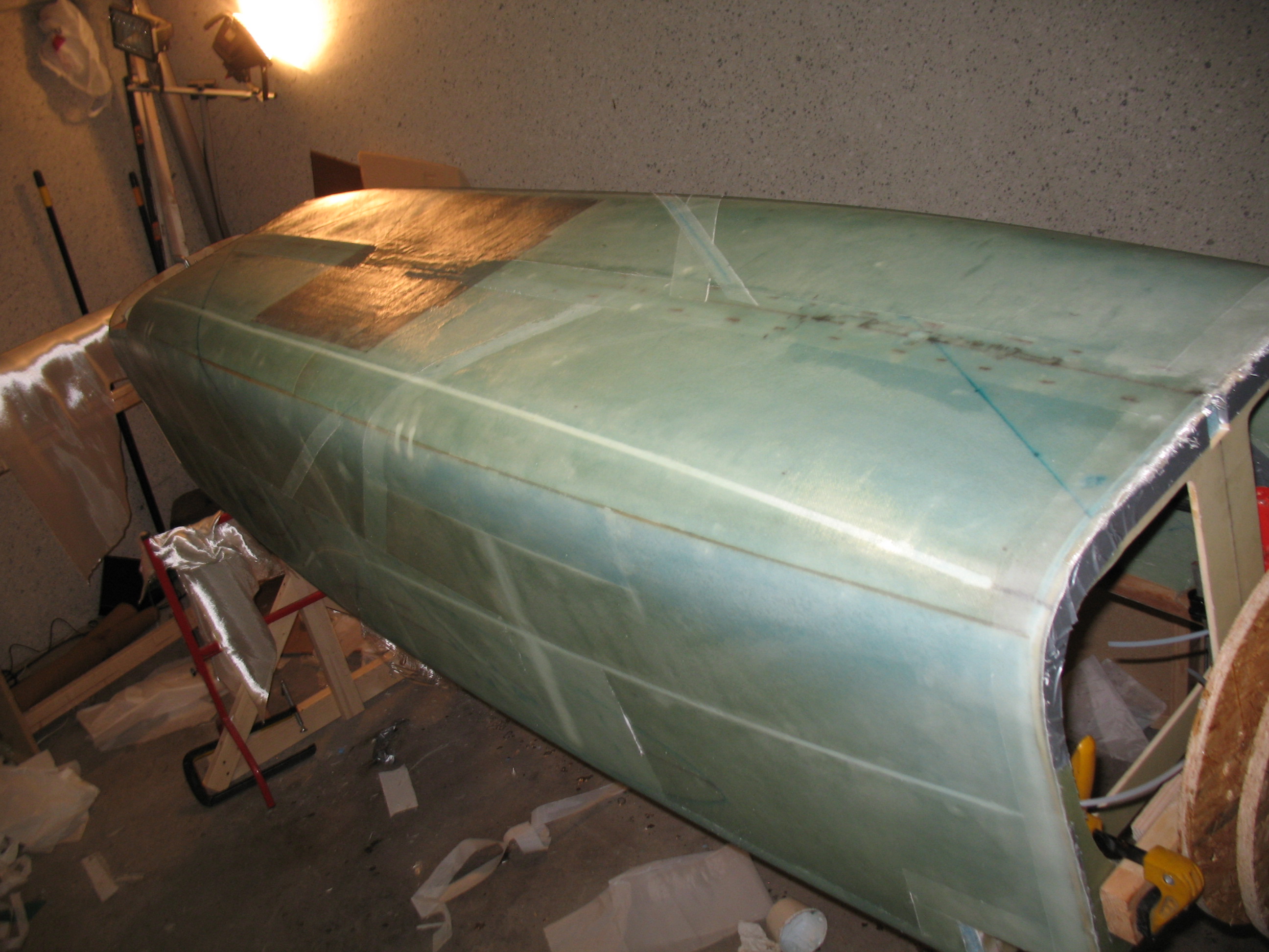
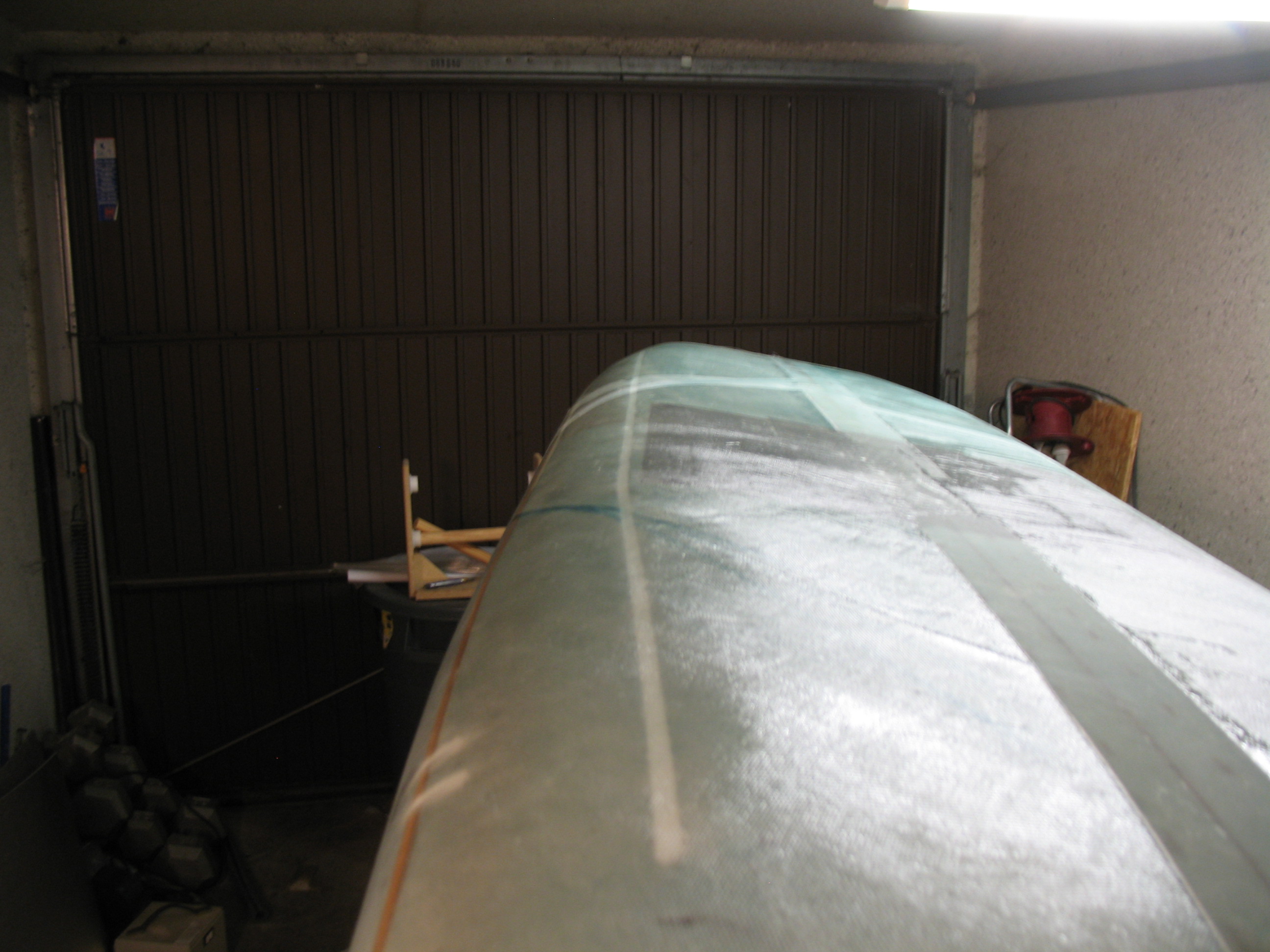
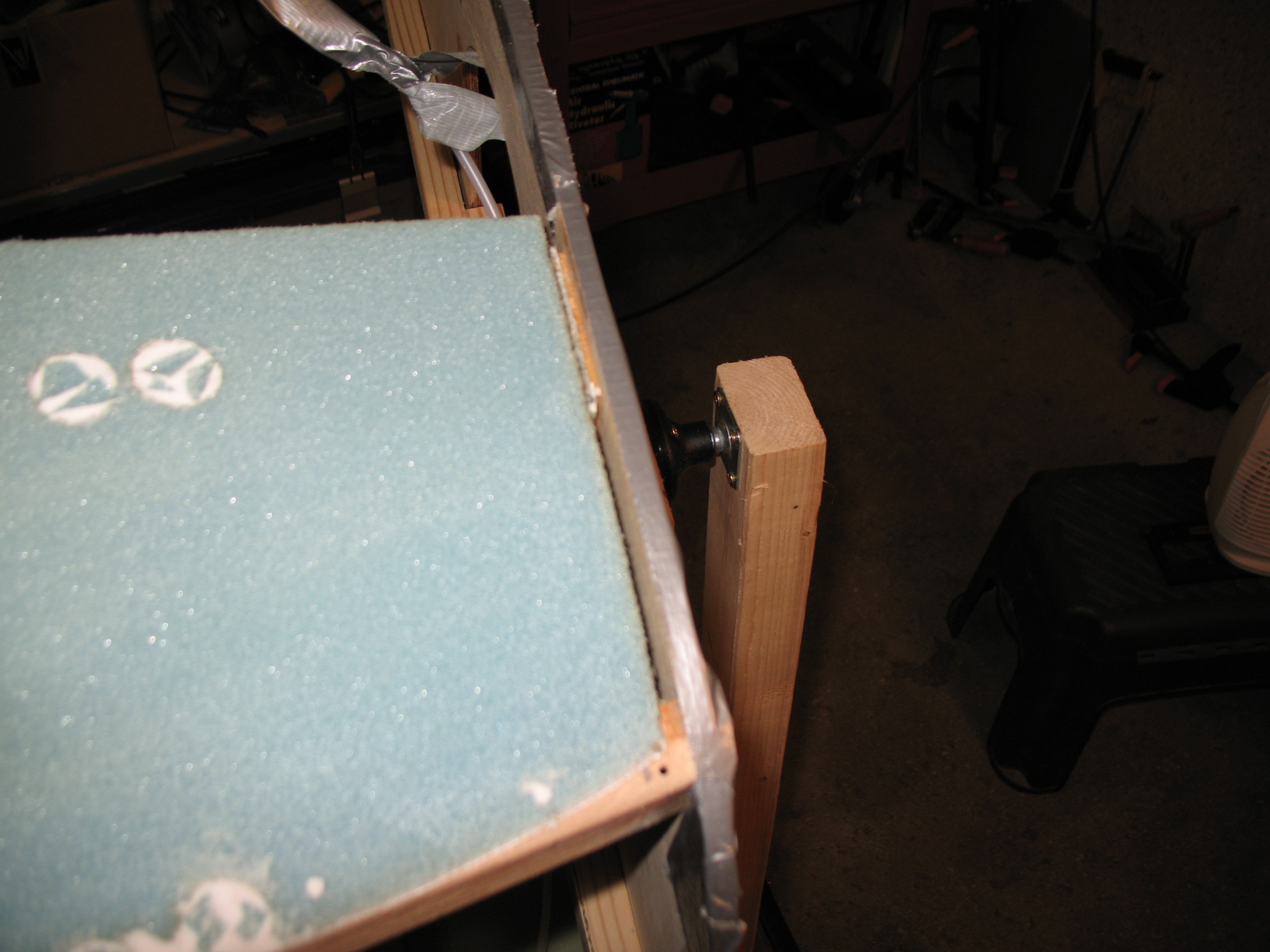
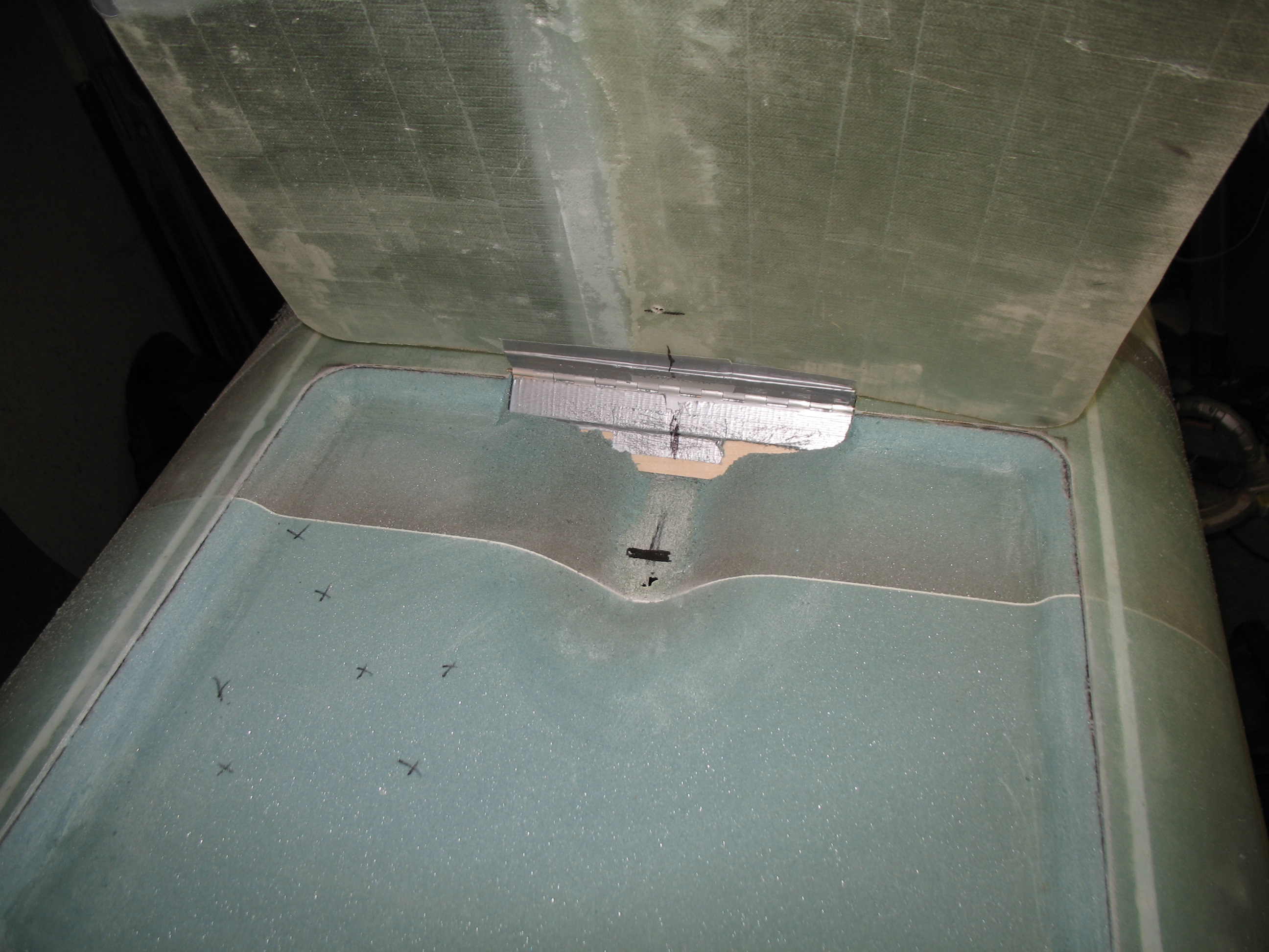
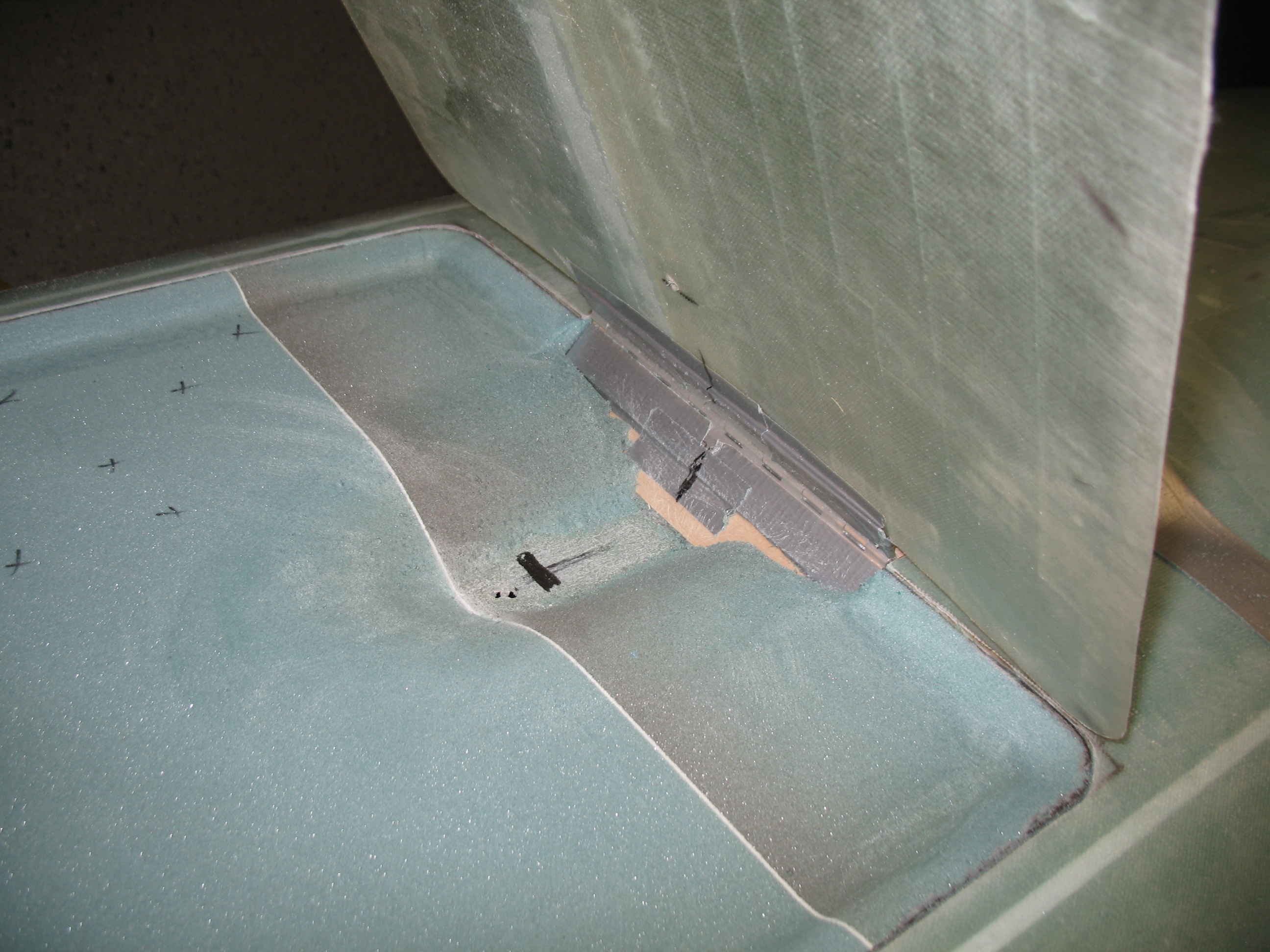
After I got the hole situated, positioned and drilled, I cleared out the foam and sanded it down to the bottom (inside-fuselage) glass just aft of LB23.  The depression is primarily for the bracket (LB18) that holds the electric actuator arm to the landing brake door.  After I sanded the foam out, I sanded and prepped the underlying glass (again, the glass that is actually the fuselage floor on the inside of the fuselage).
Section VI - Landing BrakeSection VI - Landing Brake

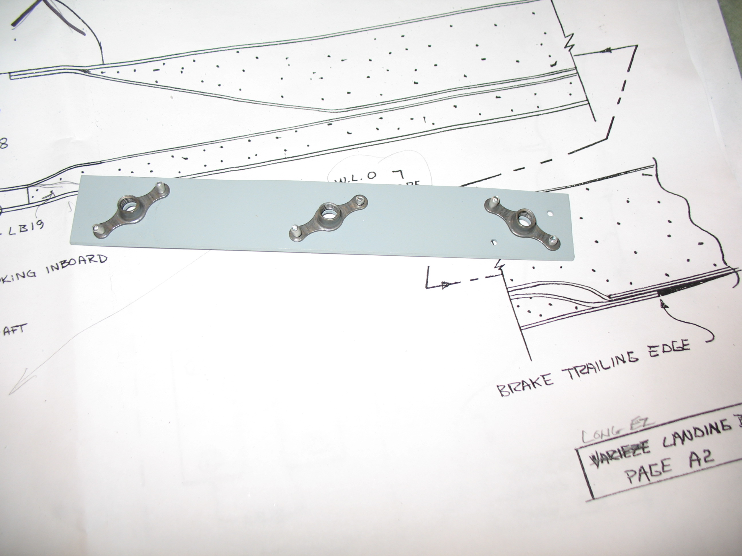
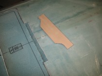
After all that mucking about with the fuselage landing brake foam, the primered 2024 aluminum plate was ready for some nutplates.  I pop-riveted the nutplates on the aluminum piece and then lined the whole assembly up with LB23.
Section VI - Landing BrakeSection VI - Landing BrakeSection VI - Landing Brake

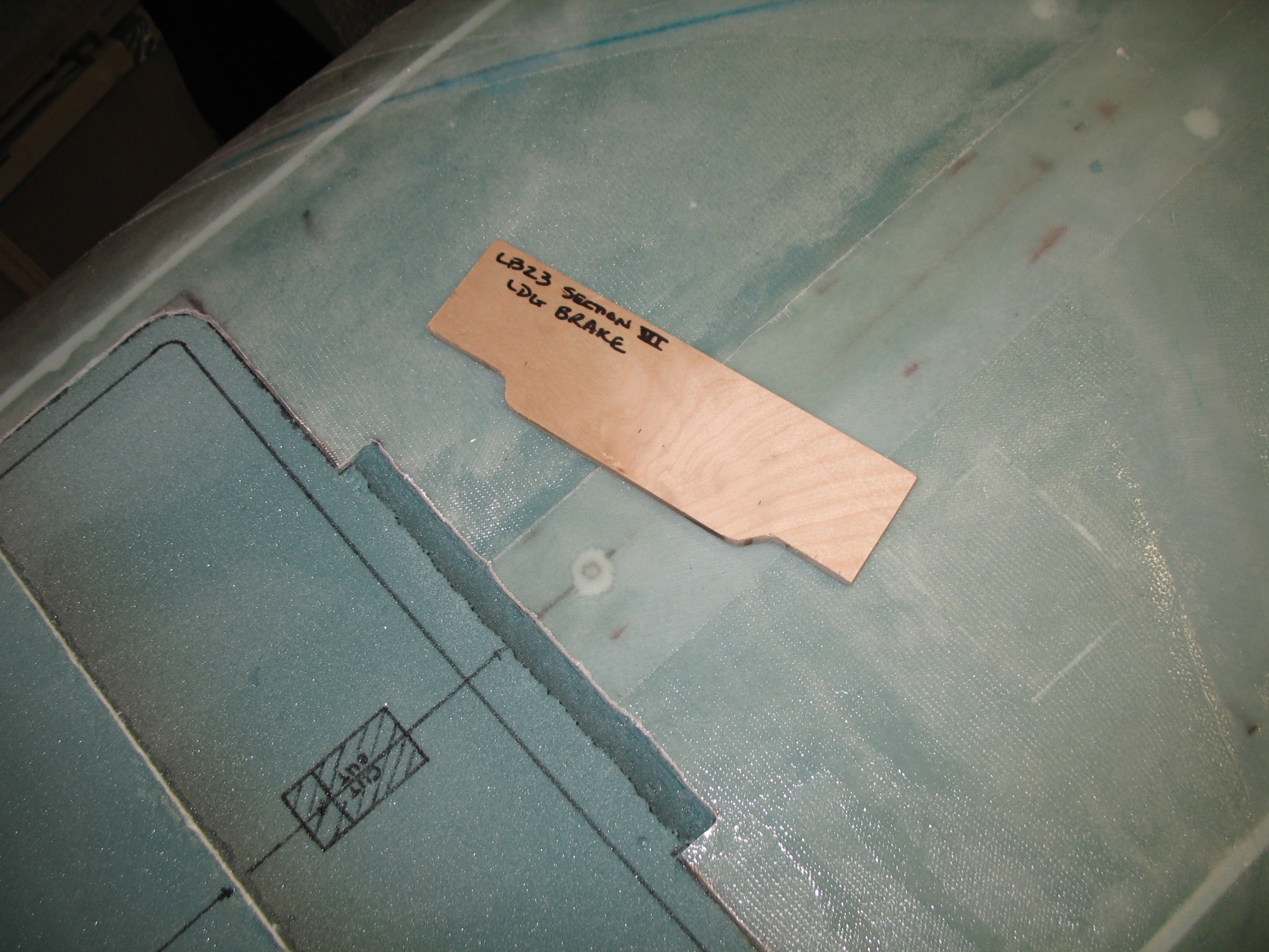
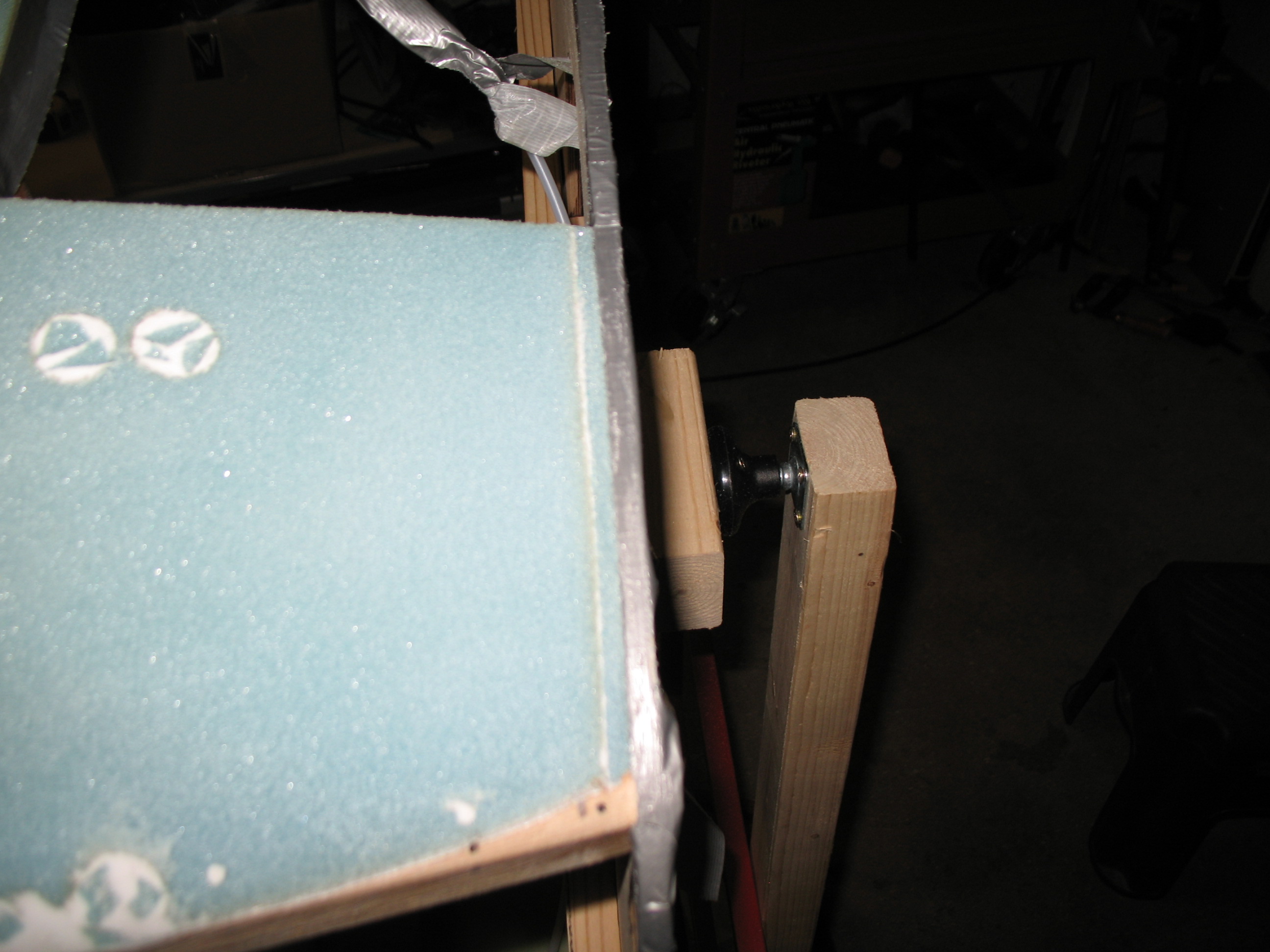
I then pre-drilled FROM THE BACK SIDE (where the nutplates will sit) the hinge mounting bolt holes (1/4″) ALMOST (but not quite) all the way through LB23.  So, on the face of LB23, facing up/out, I had 3 very small 1/32″ pilot holes showing.  On the backside of LB23 (where it mates to the nutplates), I had 3 each 1/4″ holes, matching the pattern of the nutplates, that went about 95% of the way through the plywood… so that I had one little thin piece across the top of each hole.  Why?  To ensure I kept epoxy out of the nut plates, make it easy to drill out the holes to gain access to the nutplates, and also keep the drill bit as far away from each nutplate as possible.
Section VI – Landing Brake Prep

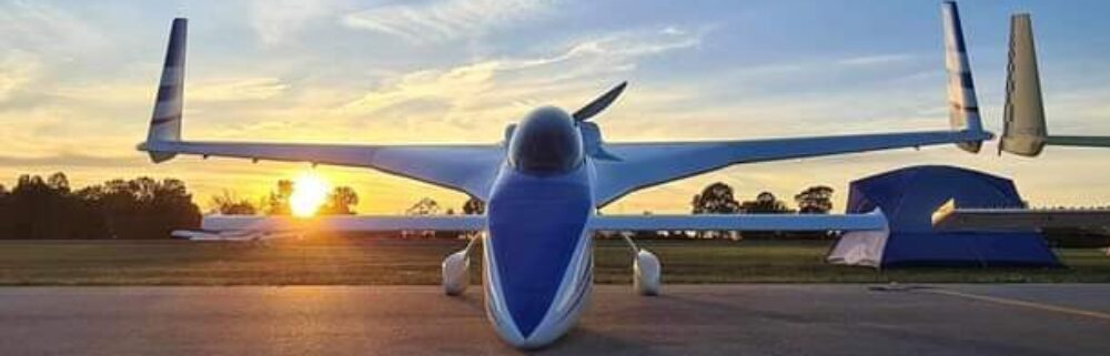
Today was a rather slow day.  Talking with Aussie Long-EZ Guru Wayne Blackler (the beautiful silver Long-EZ on the banner above is his creation), he mentioned that he would have most likely put nutplates in behind LB23, vs the plans way, to make installing the hinge bolts a much easier process.  The plans have you gluing three 1/4″ blocks of aluminum and then drilling & tapping them through the fiberglass after everything is glassed and you’re ready to mount your 3 (or 4 if you add a fourth bolt) bolts.  In thinking about it, I prefer not to drill “blind” and would rather deal with a known quantity.  So I decided to take his advice and install a thin metal plate with 3 nutplates riveted to it.  This assembly would then get floxed to LB23 and sit behind it (out of sight) and be imbedded in the foam.  Sounded like a good plan!

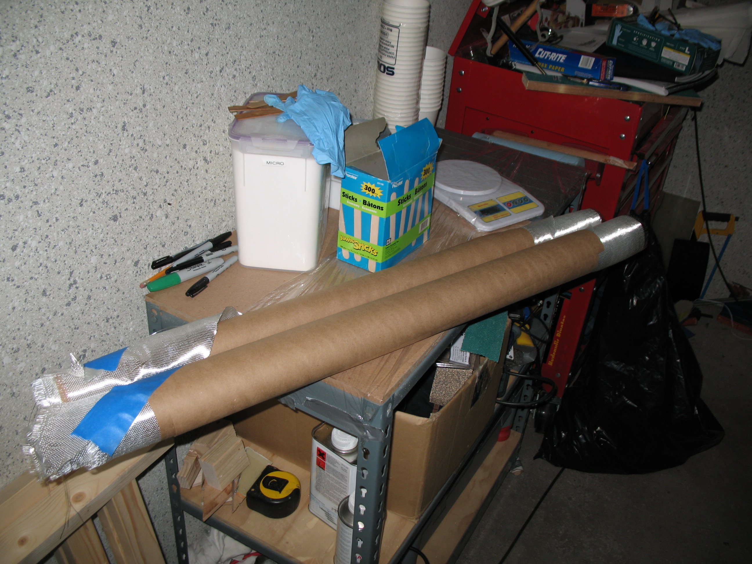
The only problem was I didn’t have any thin metal on hand, and I had no rivet capability either (although I had the full compliment of rivets called for in the plans).  So I went on a shopping spree.  I bought 0.5mm Anodized aluminum (for the nutplate) and a pop riveter set at Praktiker (German Lowe’s).  I then bought some simple green, abrasive pads and the highest end primer I could find on the base.

I got home too late to really start any shop work, so I checked out a number of CP newsletters and researched the Internet & blogs.  Part of my research was making sure I understood the (fairly) early CP switch from solid rivets to pop (cherry) rivets.

That is all!

Section VI – Landing Brake

Today was all about the landing brake.  I got all my tools and the Section VI plans together and deployed to the workshop, where I started in on some serious foam-work.

Section VI - Landing brake

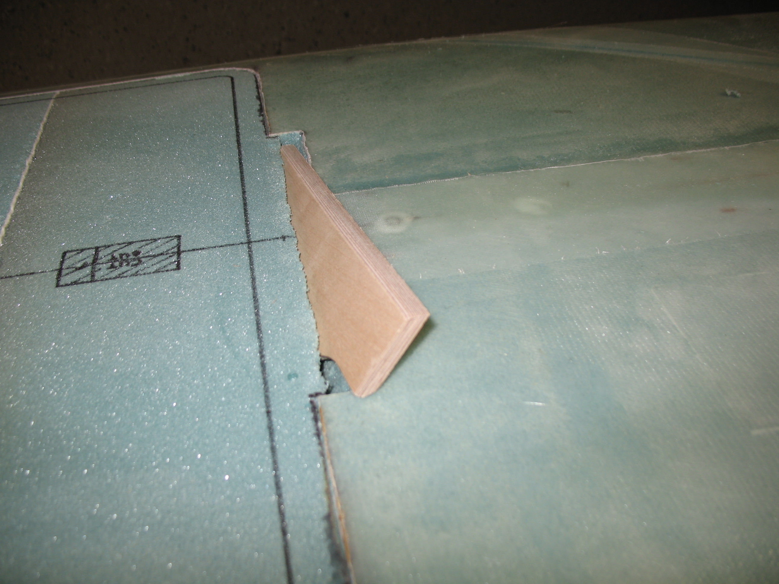
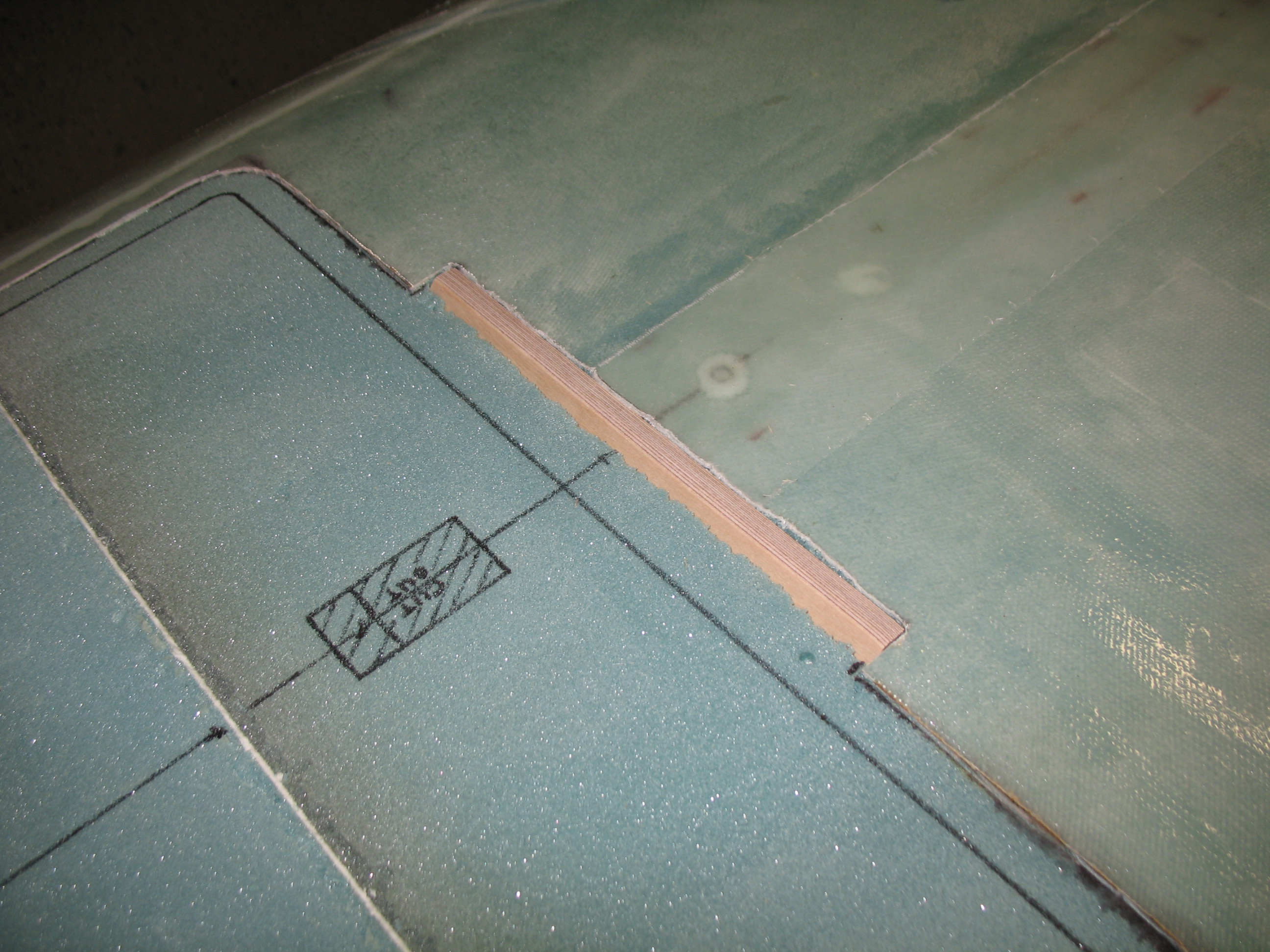
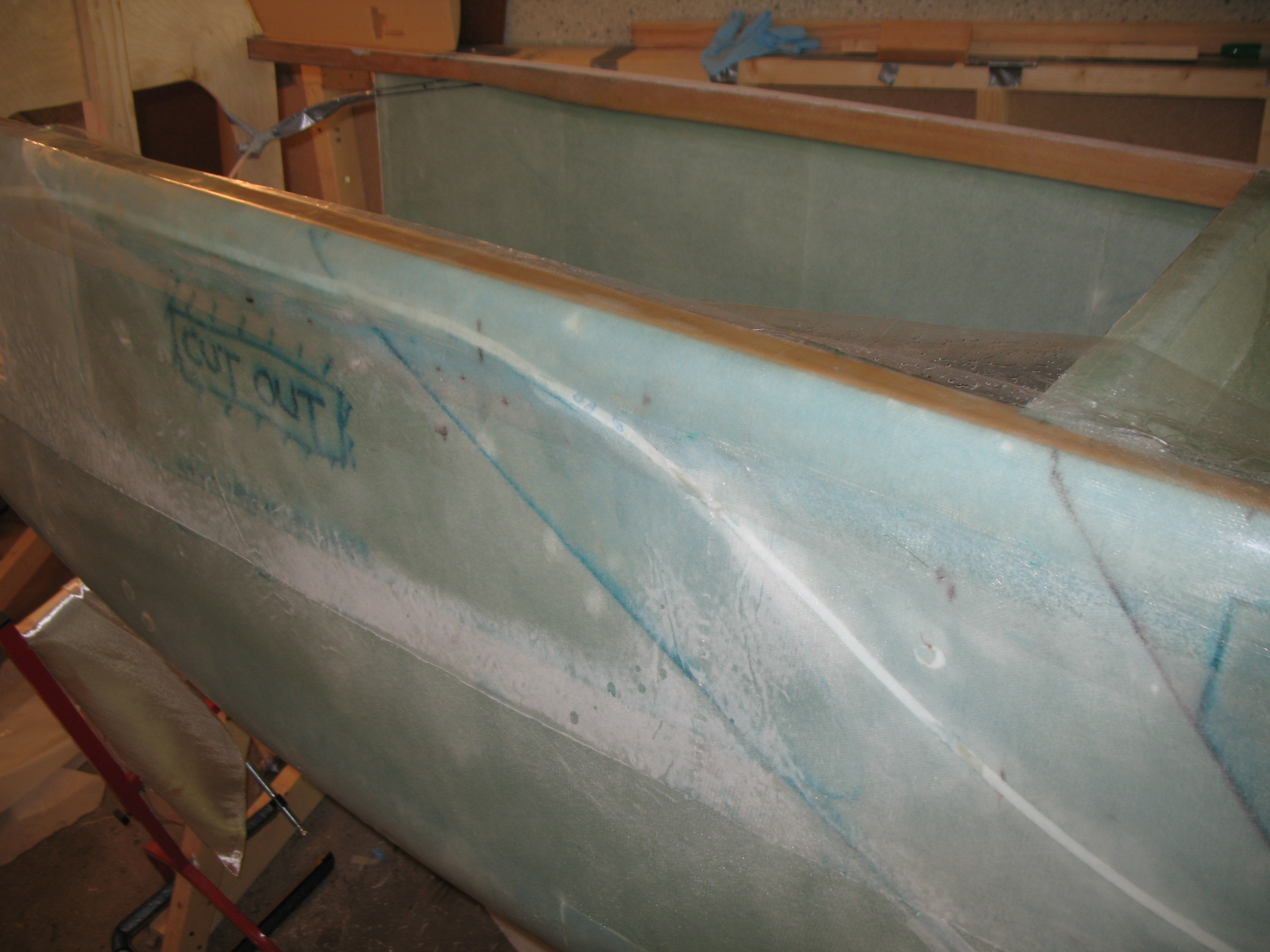
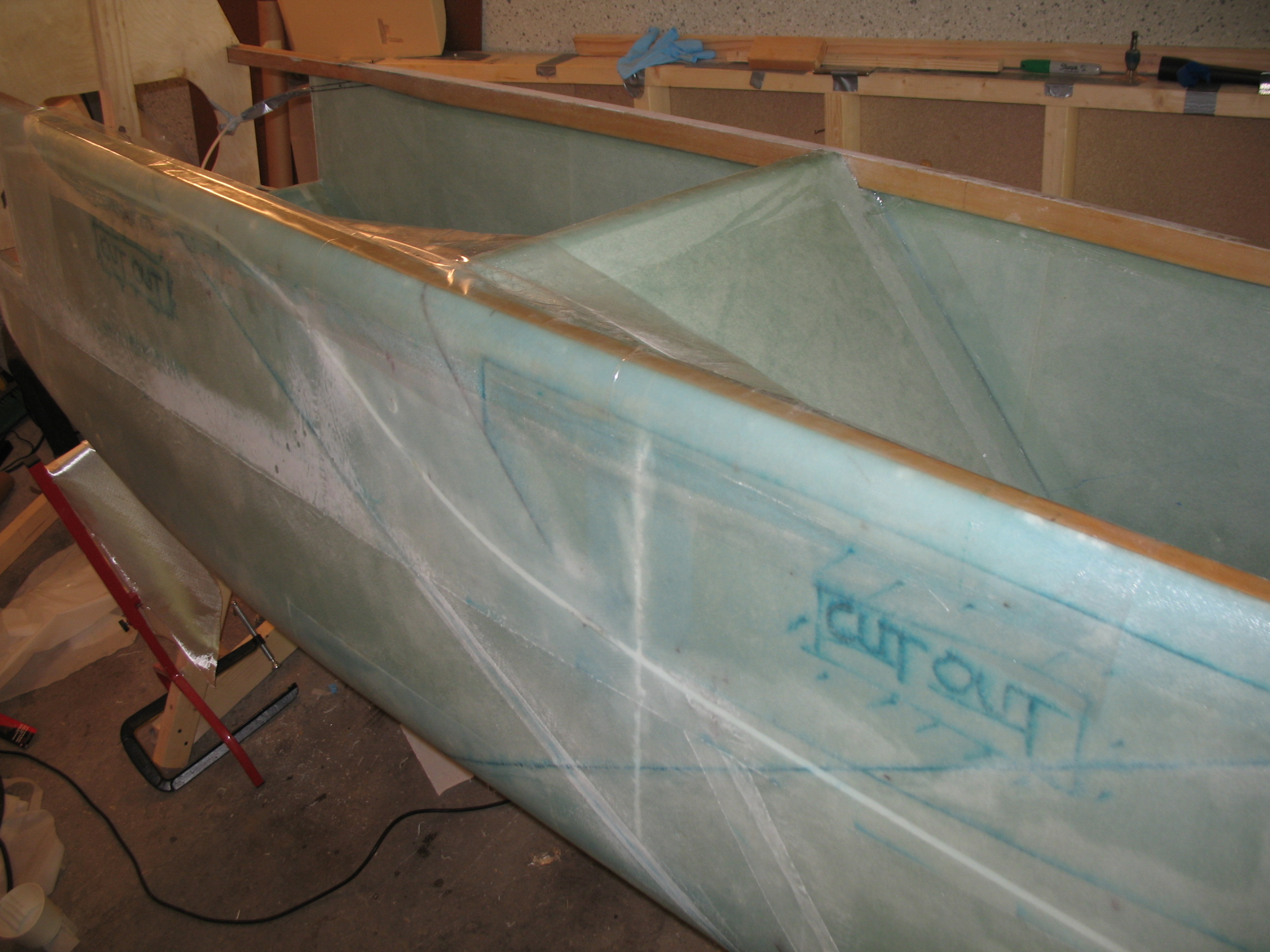
The first task out of the gate was drilling a 45° channel for the landing brake hard point, a piece of 1/4″ Finnish Birch (same stuff as the firewall), to be embedded.  This hard point, or LB23, is where the 3 bolts that attach the fuselage-side landing brake hinge will be mounted.  Quite a number of builders put 4 bolts in—why I’m not sure since I haven’t read anything stating that 3 bolts are not doing the job—so believe or not I listened to Burt and didn’t change the number of bolts (just how they were mounted!  HA!)

The channel is made by simply using a drill with a 1/4″ bit to “router” out the foam.  Not the most elegant of ways to get the channel made, but effective (and per plans… just saying!). I also used my perm-grit tools to clean up the channel and then shop-vac’d the bits of foam out.

Section VI - Landing Brake

Section VI - Landing brake

Since the landing brake sits just to the rear of the front pilot’s seat, the 45° at which the channel is cut puts the landing brake hard point right over the hump that runs down the middle of the GIB’s Left & Right foot “trays” (depressions).  Thus, the shape of LB23 could no longer stay in its initial rectangular shape (due the depressions) and required some major modifications.  LB23 had to be “dog-eared” on each side and the top and bottom edges had to be beveled at 45° so it would fit.

Section VI - Landing Brake

Section VI - Landing Brake

Section VI - Landing Brake

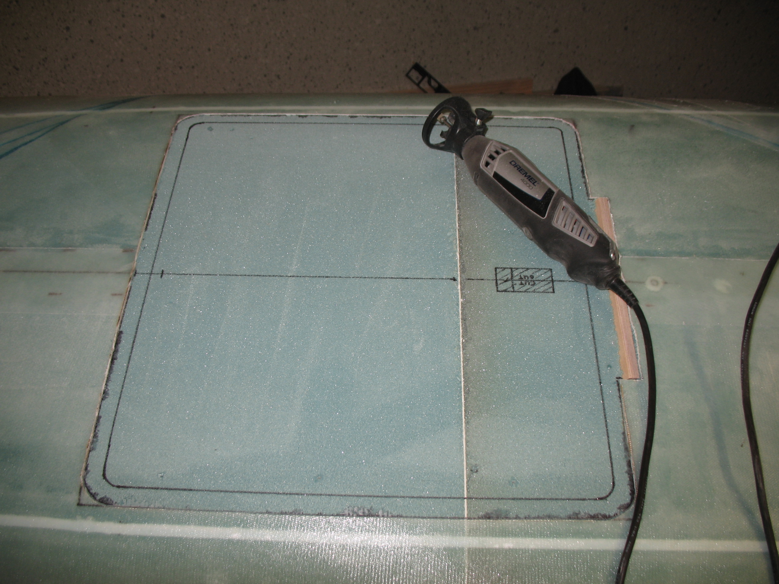
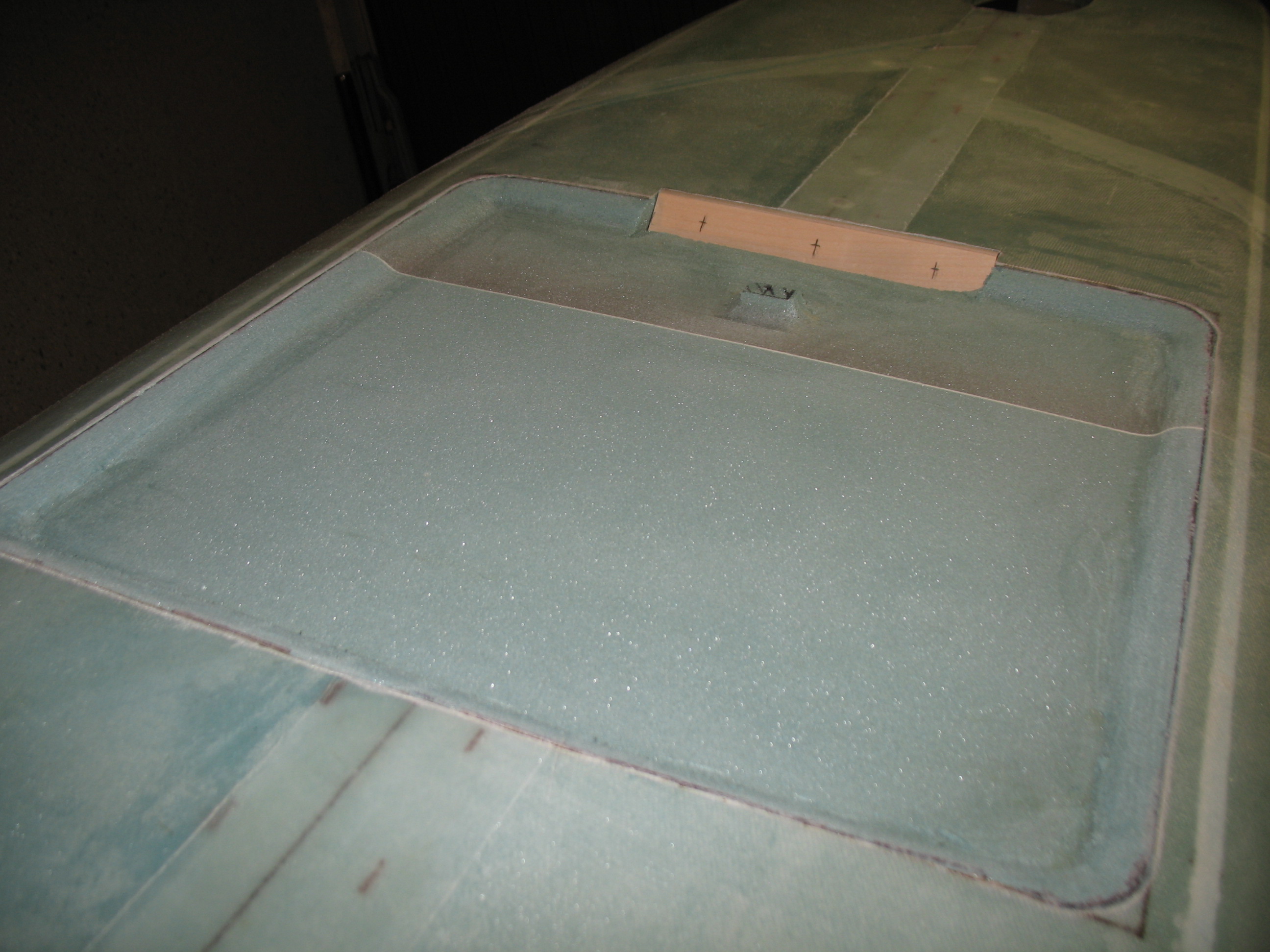
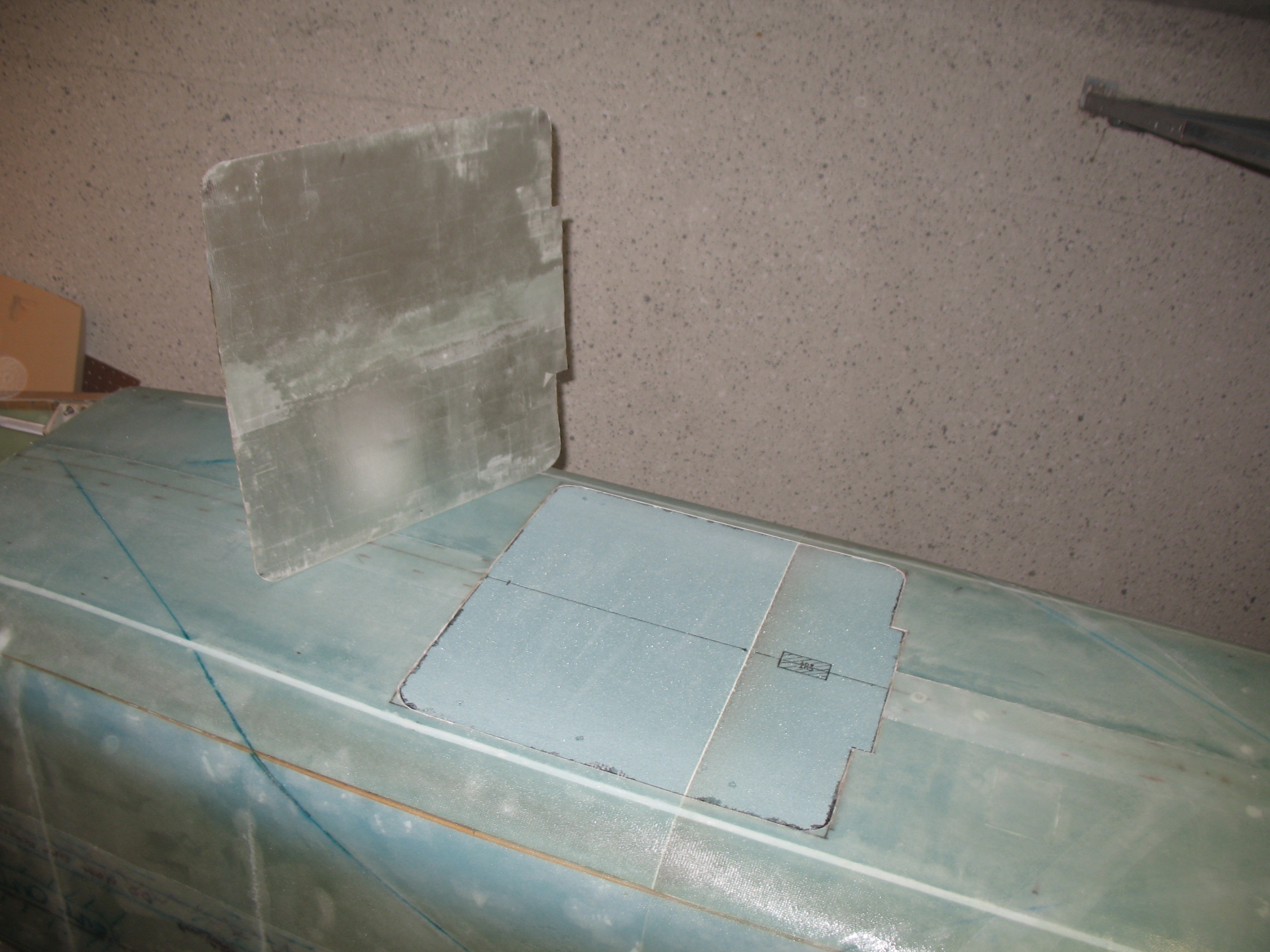
After LB23 was snuggly emplaced into its channel, I started the process of removing foam out of the entire landing brake area to create the depression needed for the brake “flap” (or door) to sit flush with the fuselage when it’s in the stowed (up) position.

Section VI - Landing BrakeI started off using the Dremel tool, but it was taking way too long with its small bit so I quickly switched to the plunge router…. which of course went a lot quicker!  Like butta!!

Section VI - Landing Brake

After I had made a rough depression by ‘masterfully’ extracting foam from the bottom of the fuselage, I sanded it with an orbital sander.  I then used a sanding block to knock down & curve the sides so it all flowed some what smoothly together.

Section VI - Landing BrakeI finished up by marking the bolt locations in LB23 (the 3 crosshairs on the wood piece).

Chapter 7 – Cutting Nose Gear Hole & Sec VI Landing Brake

Today I started out by setting up the vacuum pump outside the house and running a hose down into the downstairs work shop.  I tried my hand at a patented Cozy Girrrls lo-vac layup on a 3/8″ thick, 32″ x 48″ piece of foam.  Since a fair amount of the panels coming out of this foam was going to be for the armrest consoles, I tried some lighter weight cloth on top of about half of the BID ply I was laying up.

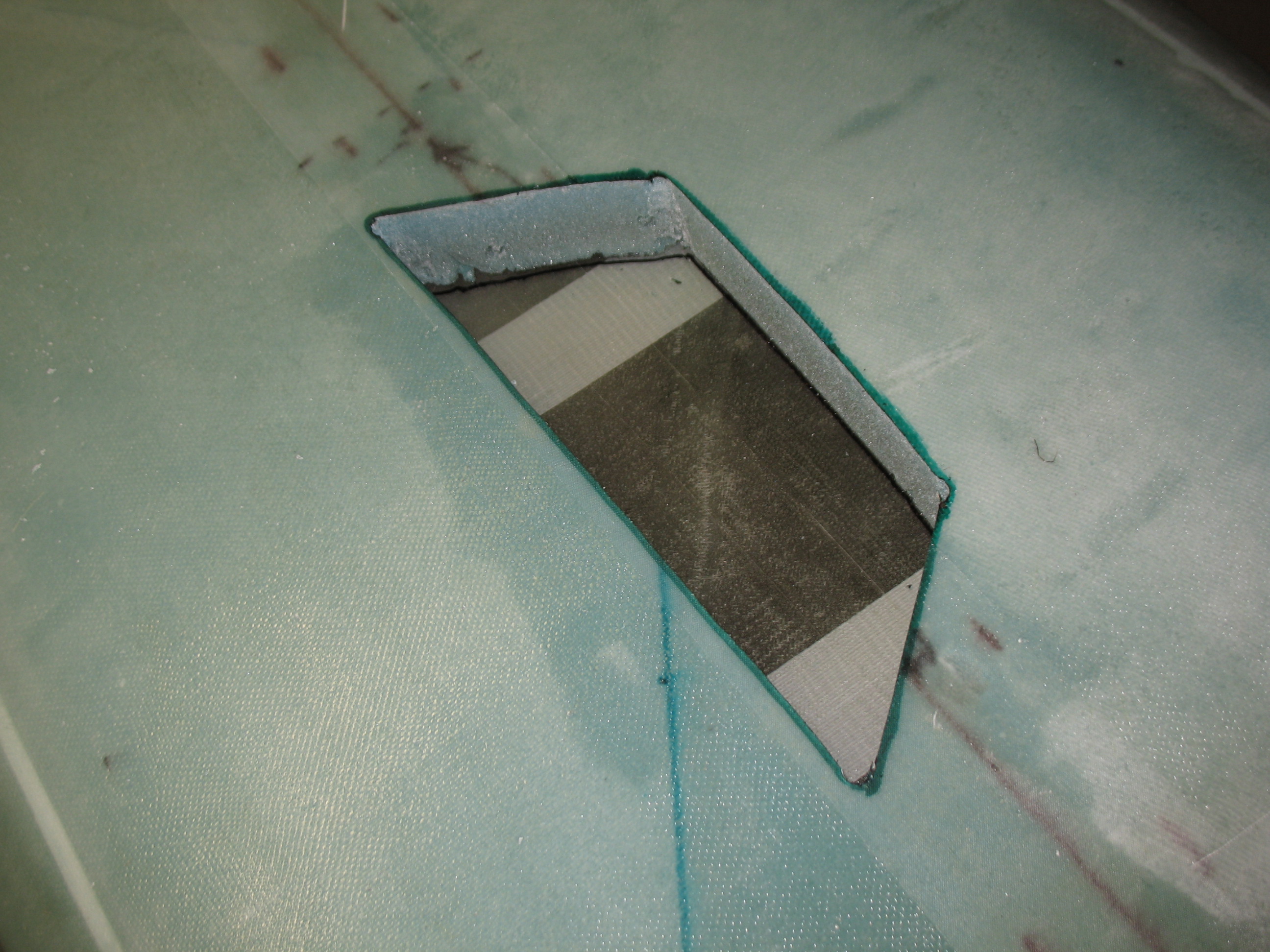
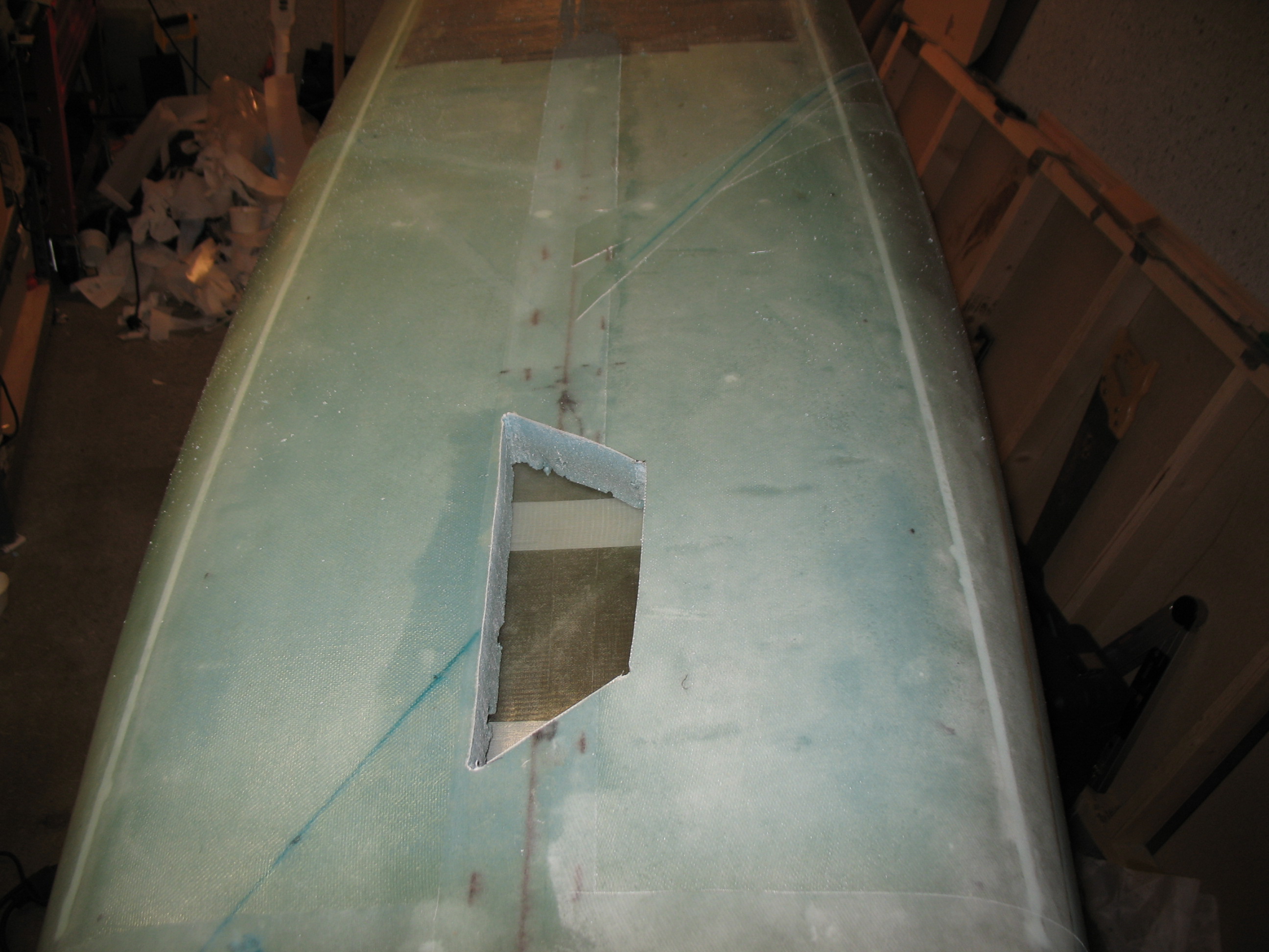
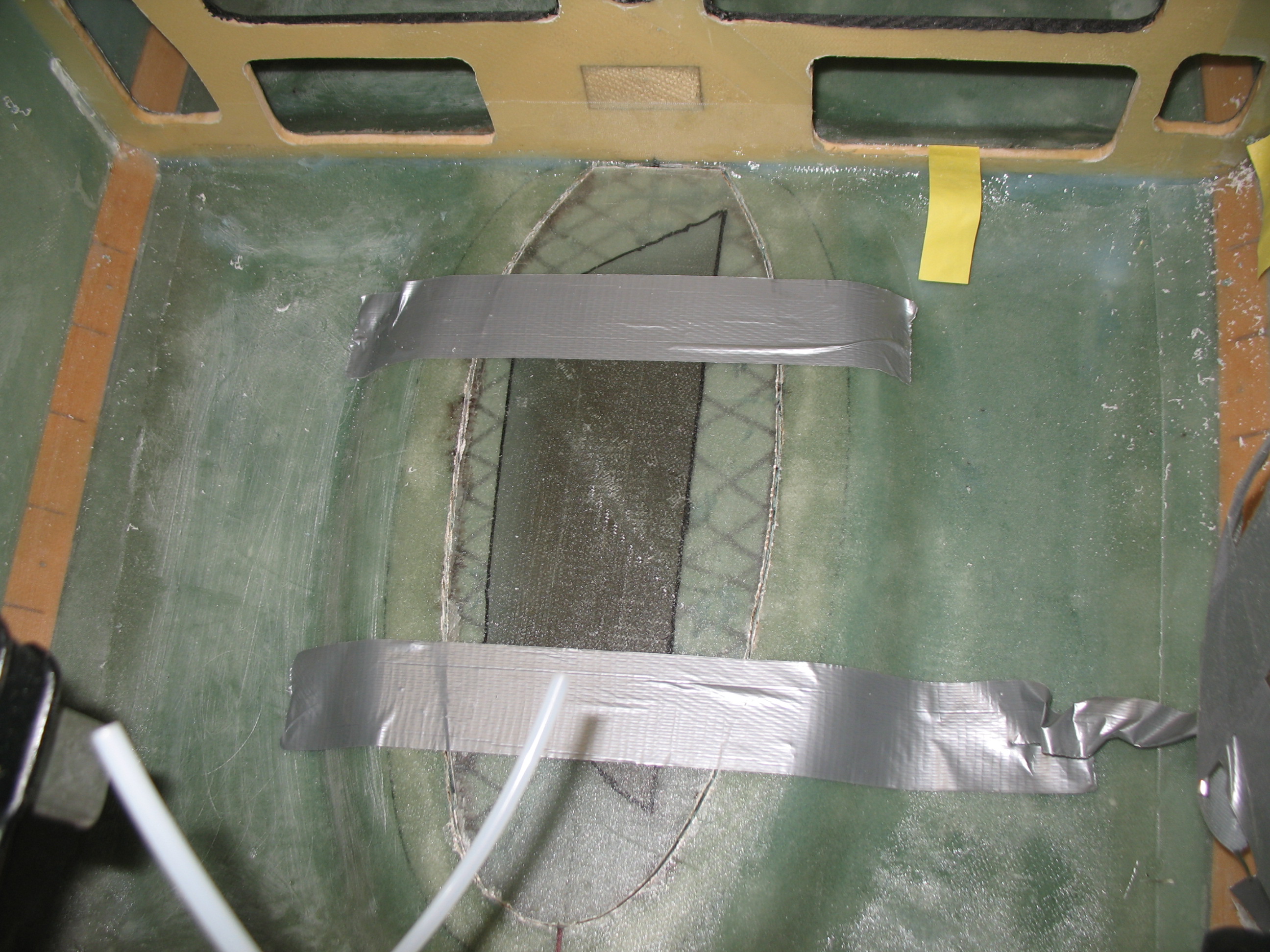
I finished up Chapter 7 (technically Chapter 6… but who’s counting??) by cutting out the nose gear well.  I started by cutting a non-symmetrical shape from the inside, since I could see the actual shape outline and then grabbed the original fiberglass nose gear hole cutout from when I Dremelled it out earlier (that was after I mounted the fuselage bottom to the sides).  After I cut the weird-shaped nose gear hole through the bottom of the fuselage, I set the cutout fiberglass piece back into place and taped it.  Once it was securely in place and back in its original spot, I traced the shape of the newly cut hole.

Chap 7 - Cutting out nose gear wellChap 7 - Cutting out front gear holeChap 7 - Cutting out nose gear holeOnce I had traced the outline of the hole, I removed the fiberglass cutout piece and moved it to the outside of fuselage to transfer the shape of the landing gear hole.  Once I transferred the nose gear hole outline, I simply grabbed the jig saw and cut out the front nose gear hole.

Chap 7 - Nose gear hole cut outChap 7 - Cutting out nose gear holeIf the nose gear hole looks a little non-symmetrical and uneven, it’s because it is.  Since the plans have you cut it to shape based off the nose gear cover (NB), which is a purchased part, there’s not much you can do since it comes that way!  However, once the nose gear cover was set into place the lopsidedness of the hole was fairly obscured.  And once gear wheel doors are built and set in place, the irregular hole will be virtually invisible.

Chap 7 - Testing nose gear well cover

Section VI – Landing Brake

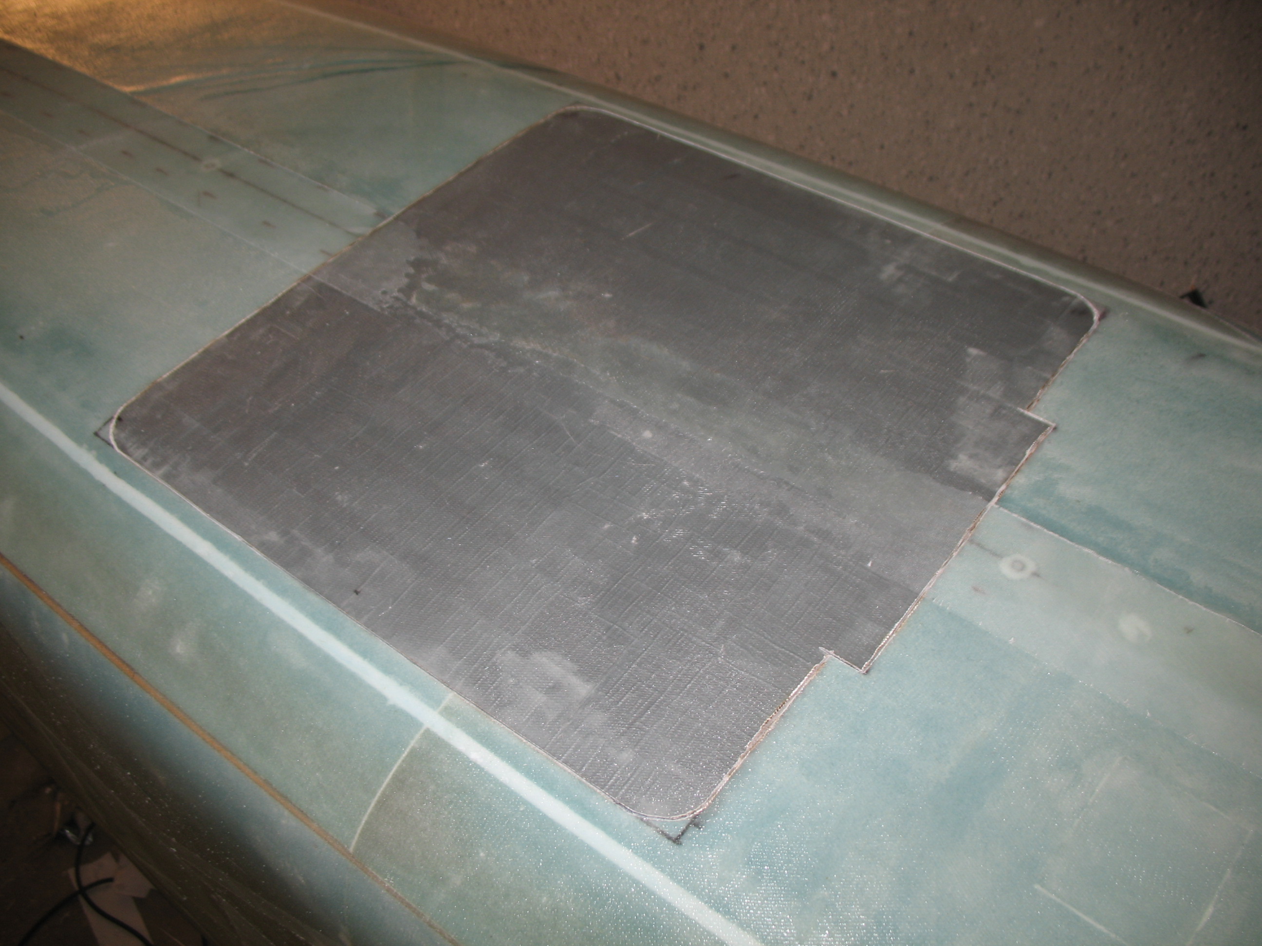
After I got the nose gear hole cut out and test-fitted the nose gear cover, I started to work on the landing brake.  If you remember, well before I skinned the fuselage I covered what would become the landing brake area with duct tape.  Now with the fuselage glassed, I took the Dremel and carefully cut the outline of the landing brake and removed the fiberglass brake outline and duct tape.

SectionVI - Cutting out landing brake skin

Section VI - Cutting out landing brake

Section VI - Cutting out landing brake

Finally, I got the CSA “Wortmann Gear Fairing” information from my buddy Marco, which I then incorporated into my gear planning.

Chap 7 – Final Fuselage Glassing

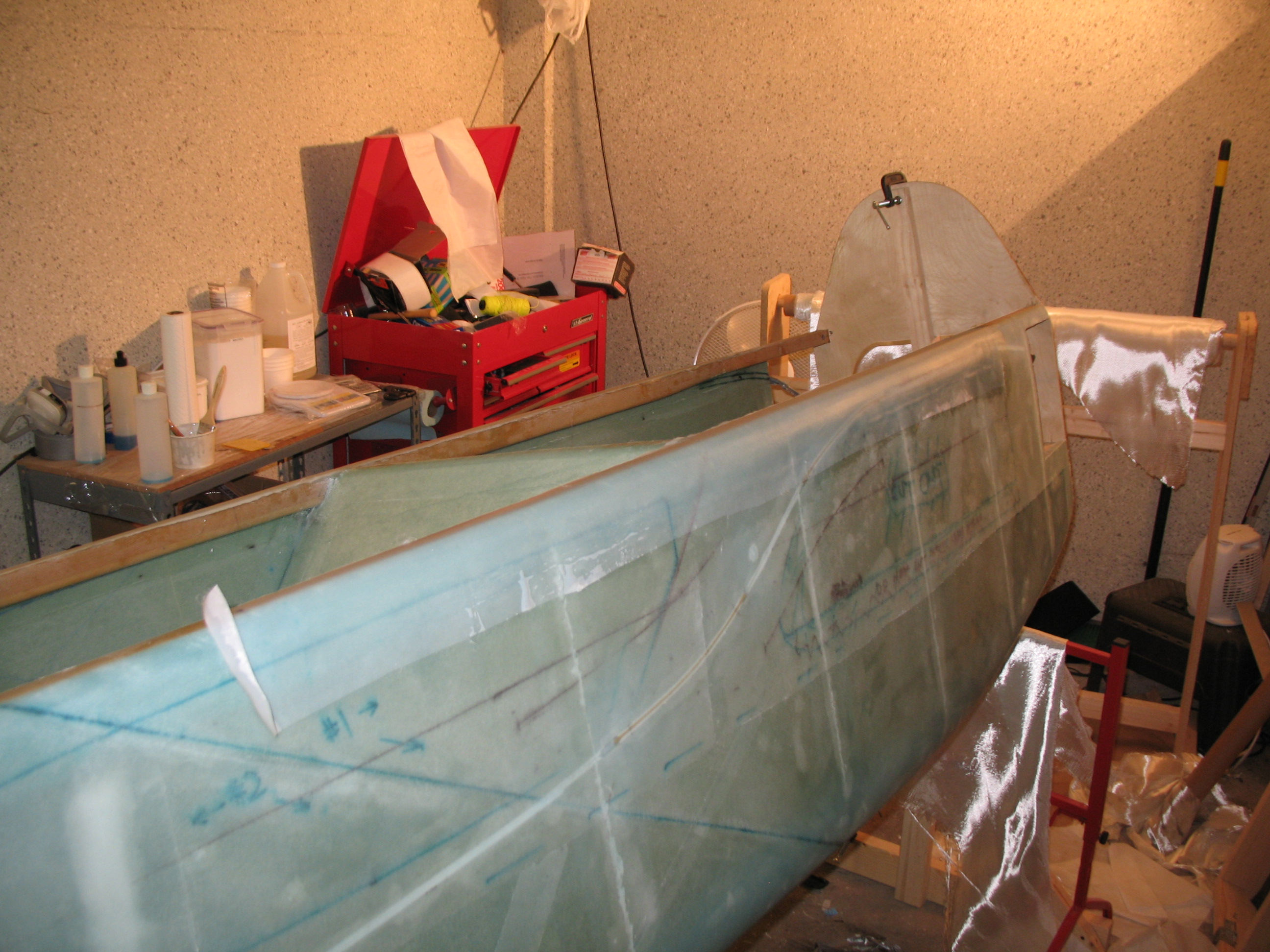
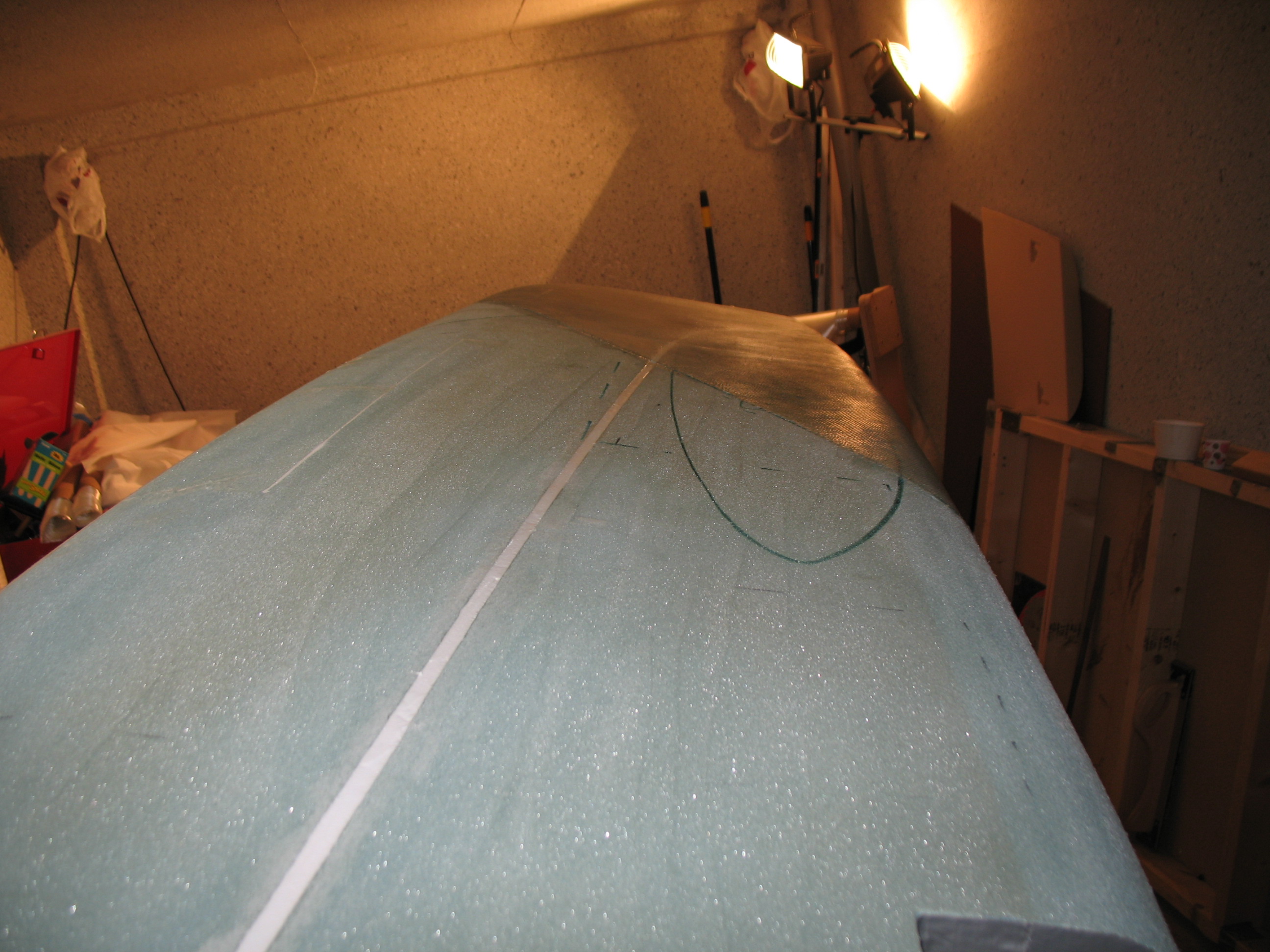
Today I started a massive multi-hour campaign to clean up “peel-ply snot” from the areas left from pulling up peel ply.  Peel ply is great, but the raw carnage it leaves behind is something I think we plastic airplane builders forget over time.  Anyway, with a fairly string-free fuselage I proceeded to prep for laying up the two sets of 3-ply 3″ UNI “tapes” (cut UNI cloth) along the top of each of the upper longerons.

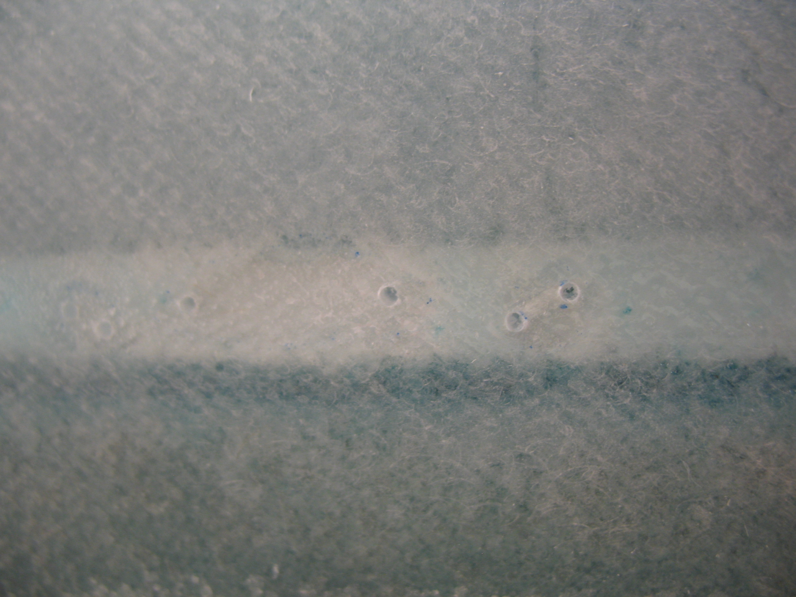
Before I could layup the UNI tape sets, I had to take care of few air bubbles that insidiously crept into my fuselage glassing layup, mainly over the upper conduit areas.  I used a hand drill to make a couple of holes in the glass and syringed in some epoxy.  They weren’t that large, maybe .2″ to .4″ at the most (oblong, not round) here and there, but since they were right under my UNI reinforcement tapes, I wanted as much strength as possible.
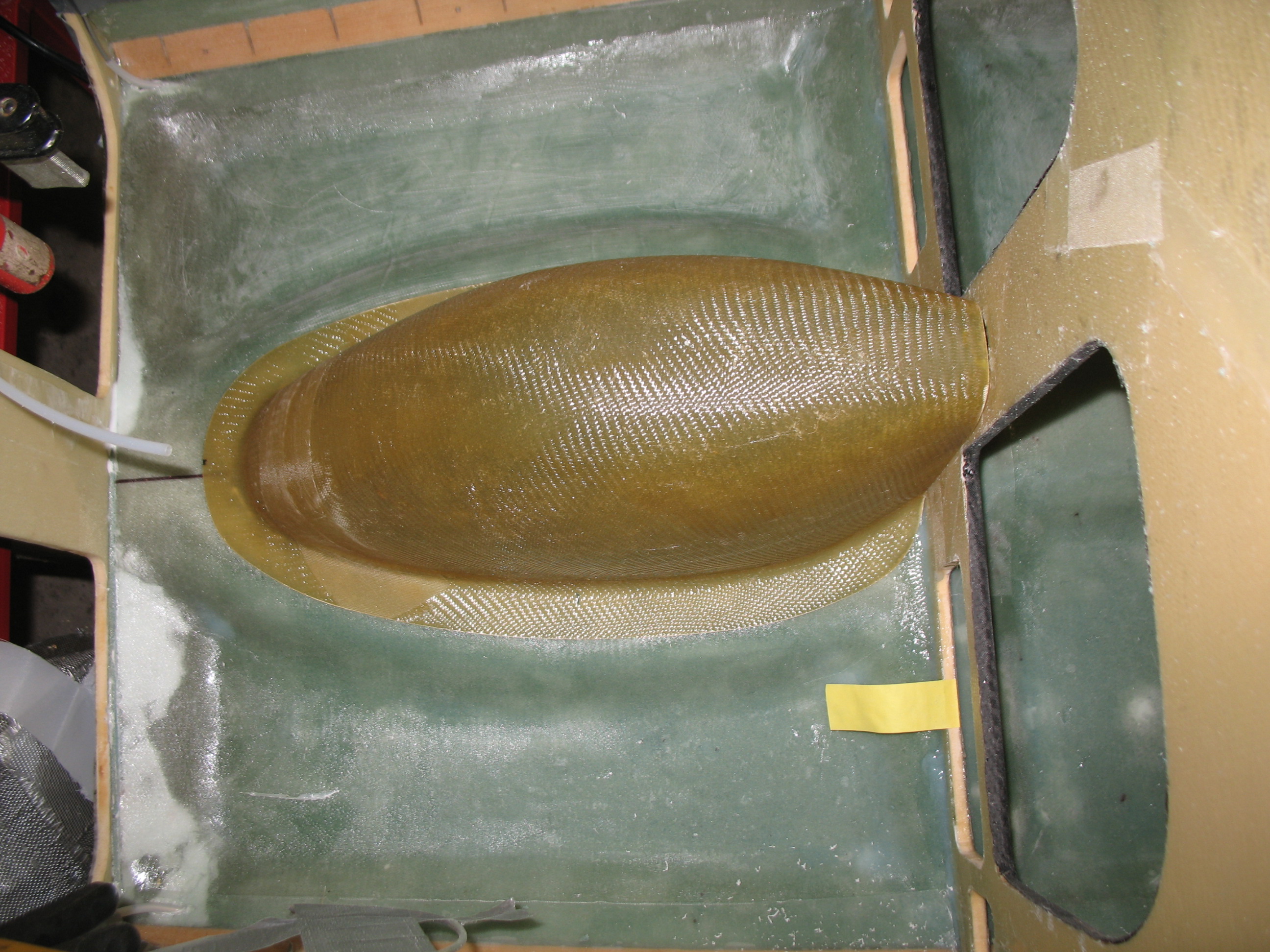
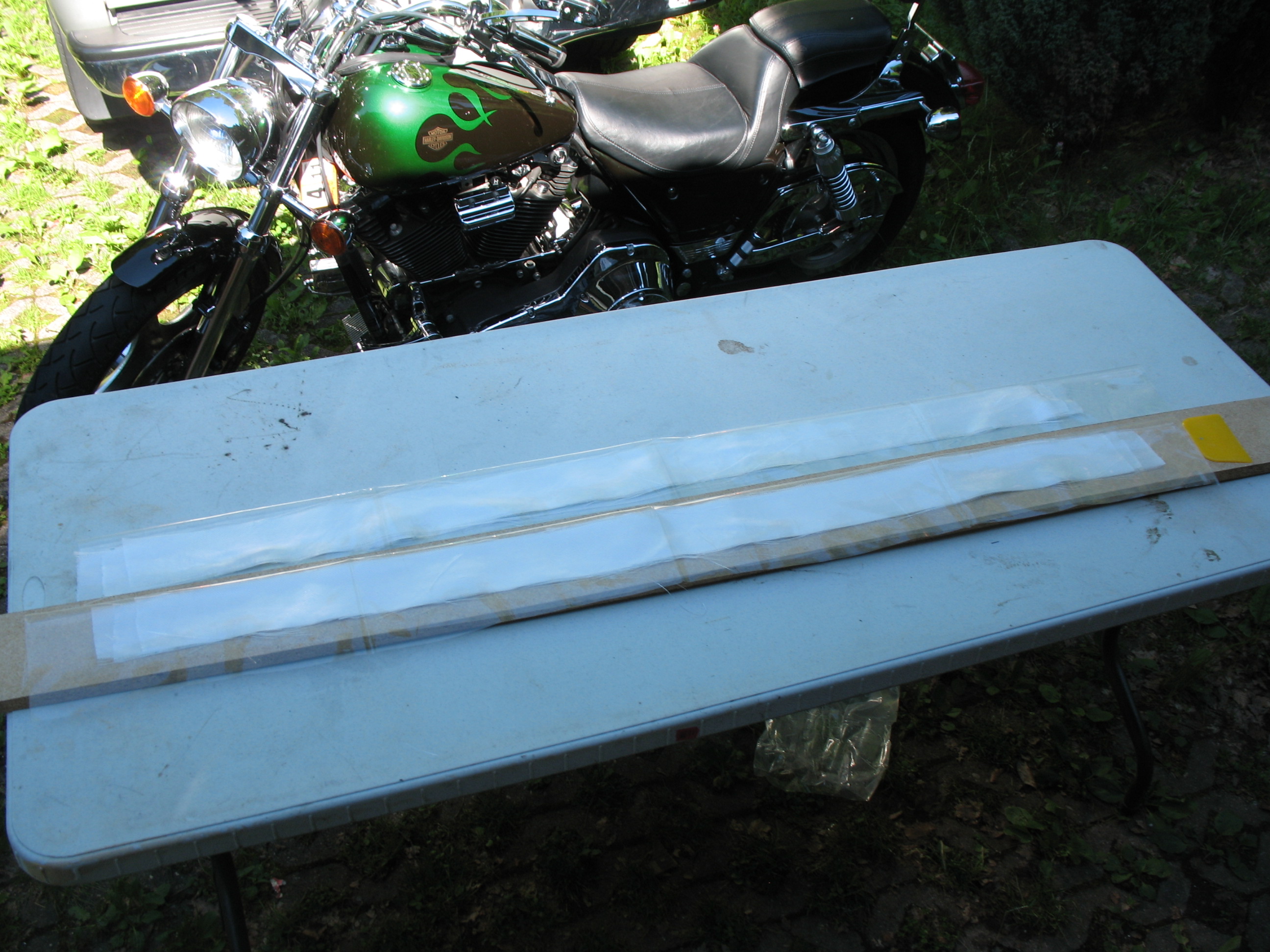
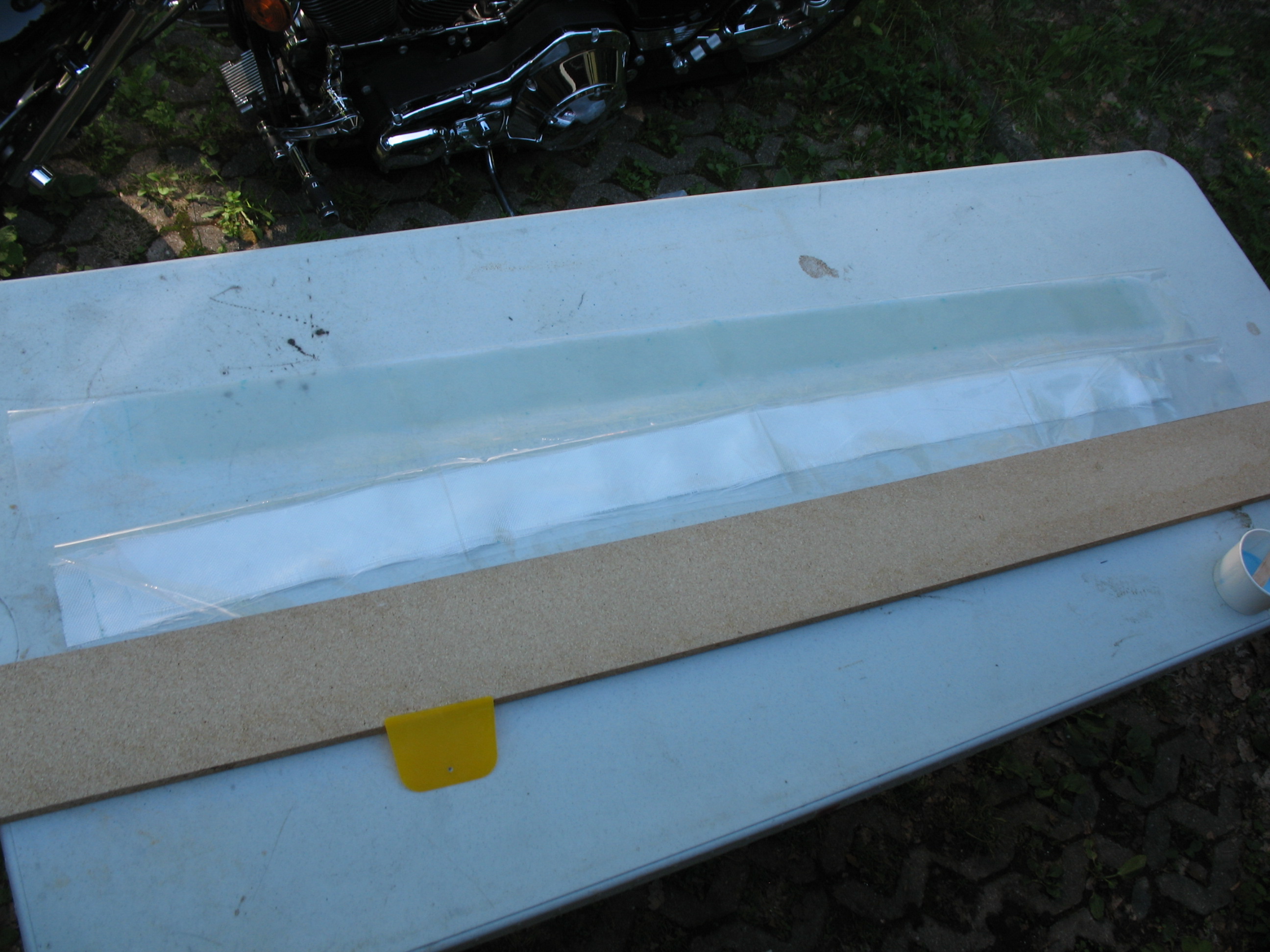
Chap 7 - Injecting epoxy to clear out some air bubblesAfter removing the offending air pockets with injected epoxy, I started prepping for my 3″ UNI reinforcement tapes layup.  I set-up my portable table and got a length of scrap particle board to use as a base for my squeegeeing activities.  I then grabbed my 3″ UNI tape prep-preg set-ups and went to town.

Chap 7 - 3 x 3" UNI longeron reinforcements

Chap 7 - 3 x 3" UNI longeron reinforcement tapes

Remember, since I’m removing a little bit more fuselage side material for a longer strake opening on each side, I added 2″ to each end (4″ total) of the 3 UNI tapes for final lengths of 54″, 52″ and 50″.   I wet out one set of the UNI pre-preg and laid it up on the Right longeron.  Once I had the Right-side longeron layup good & peel-plied, I moved on to the Left longeron.

Chap 7 - 3 x 3" UNI longeron reinforcement tapes

Chap 7 - Glassing 3" UNI longeron reinforcement tapesChap 7 - Glassing 3" UNI longeron tapes

Chap 7 - Glassing 3" UNI longeron tapes

 Chapter 7 – Fuselage Exterior is complete!!!

Chapter 7 – Skinning the Fuselage

And so begins the final chapter in the saga of glassing the fuselage … or should I say the final step . . . of the chapter!

I pulled an all-nighter to glass the fuselage.  The first the few hours were of course all about prepping EVERYTHING to get ready to actually start glassing.
Chapter 7 - Prepping fuselage for skinning

I cut two sets of 3″ UNI strips at 50″, 52″ & 50″ and set them up “pre-preg”.

I cut 2 pieces UNI for the third ply on fuselage & wrapped/rolled in brown paper.

Chapter 7 - Glass for skinning fuselage

I cut a UNI roll at 30° on the end and took it out the garage.

Continue reading

Chap 7 – Fuselage Glass Prep: T-minus-1

Today I finalized the fuselage preparation for glassing the exterior skin of the fuselage.

While I was double-checking everything I realized that at some point I had been a little aggressive in my sanding & cutting of the foam at the back edge of the fuselage where it butts up to the firewall, on the Left side of fuselage.  This past overzealousness created a small gap that needed to be filled, so I made up a foam wedge that was 0.2″ wide from front to aft, around 0.4″ deep (depth of foam in that location), and approximately 6.2″ in length from top to bottom.  I then micro’d this foam wedge into place to cure.

Chap 7 - Rear fuselage foam repair

Continue reading

Chap 7 – Fuselage glass prep continues!

Greetings Dear Readers!

The good news is that I have much to report. The bad news is that I only have one pic to share . . .

Today I organized and cleaned the garage in preparation for skinning the fuselage exterior. I sanded down the lower stringers and then vacuumed the entire fuselage.  I then finished taping the lower aft section of the fuselage and the main landing gear brackets in the “hell hole” area near the firewall.

I pre-deployed glassing supplies out to the garage.  I also added another 45° brace on the fuselage glassing spit.

I marked the top longerons for the layout of the staggered 3-ply layup of 3″ UNI “tape” (NOT actual UNI tape, this is just plies of UNI cut into 3″ strips).  Because I will be employing the Steve Volovsek/Ken Miller “Elbow Room Mod,” which enlarges the strake openings in the side of the fuselage further aft, I decided to add 4″ to each top tape so the resulting lengths are 56″, 54″, 52″ for each side (all obviously 4″ longer than plans).

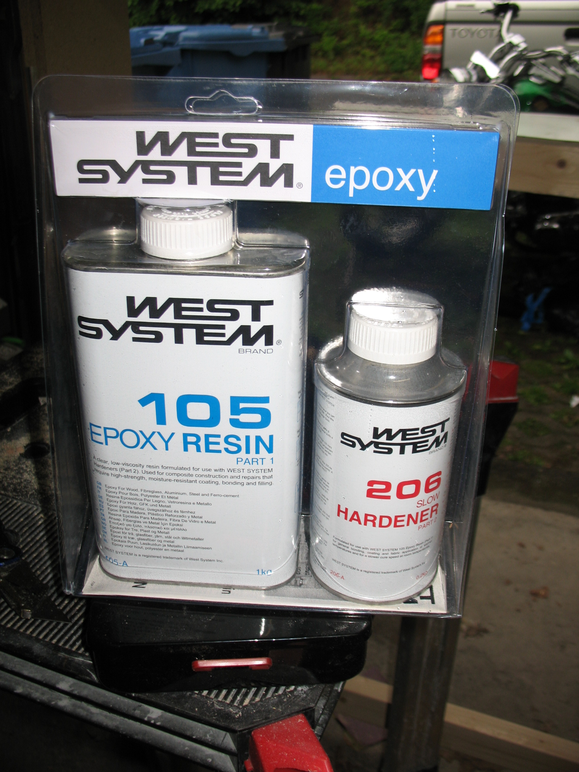
Finally, I’ve been researching the final fiberglass finishing techniques and systems for the last few weeks.  I think I’ll go with West, but because of some reservations of a couple of actual builders that I’ve been discussing this with (who used other systems), I’m going to test it out first.  I picked some up from a boating supply store here in Germany for my tests.

West Epoxy System