Switching Epoxies

After a couple of discussions with a few members of the “Old Canard Guard,” including one of my building mentors, Dale Martin, I decided to pull the trigger and switch from MGS 335 to MGS 285.  While the epoxy itself isn’t that much more expensive, the slow hardener incurs a hazardous shipping penalty usually on the order of $45 per quart.  Yes, that’s on top of the cost of the hardener and the normal shipping fee!
MGS 285 hardener

So why did I switch?  Well, primarily safety.  After reviewing Gary Hunter’s Do’s & Don’ts of Epoxy Resin, I decided I should go after an epoxy that gives me the highest Tg.  I was already using the MGS system, so I was familiar with the system.  Plus, I’m moving to Germany in late July for a couple of years, so after a bit of research I’m fairly certain I can buy the MGS where it’s actually made and pick it up in bulk quantity ala Sam’s Club style.

Also, for the remainder of my build tasks here, I was also able to find a company in California to sell me two quarts of the fast hardener for  the $45 hazardous shipping fee.
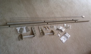
Cozy Girrrl Metal Parts Arrive!

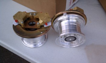
Santa (UPS guy) came today!  Got my hardware from the Cozy Girrrls, and it’s some really nice looking stuff!  All the parts are either cadmium plated steel or Alodined aluminum for corrosion control.  Still trying to figure out all the pieces and I have to flip through the plans a bit to remember what is going to go where.

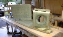
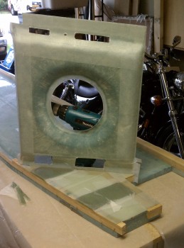
The long tubes are for the elevators that hang off the canard.  The two quasi-triangular shaped pieces in the middle-left with three holes drilled at the bottom are the mounting tabs for the canard.  Normally these are 1/8″ thick but I opted for the 1/4″ thick ones because they were only just a tad heavier, twice as thick and available!

Right now I need the Main Landing Gear Mount Assemblies (LMGA) and here they are.  The instructions on how to put this all together and what goes where is on the large plans drawing Page A5.

IMAG0155

Chapter 5 – Fuselage Sides

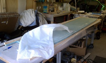
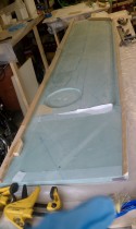
Learning from the pain it took to remove the half-dozen individual pieces of peel ply from the right fuselage side taught me to make the process easy by just peel-plying the left fuselage side lay-up with one huge piece of peel ply!  Here I’m removing that one big piece of peel ply.  I’ve already mounted the top longeron with flox to the fuselage side, and the lower triangular stringer is cut and teed up for mounting as well (thus the reason I’m removing the peel ply at this point).  With no control stick depression on the left fuselage side, and having glassed one side already, the left side went significantly faster than the right.Left fuselage side peel ply removal

Chapter 5 – Fuselage Sides

Below is the left fuselage side ready for glassing (the picture is bit blurry).

Left Fuselage Side


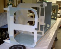
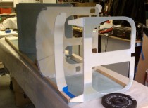
Next, these pics below show various shots of the fuselage bulkheads built in Chapter 4 being fitted in place to their locations on the right fuselage side.

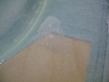
Finally, below is a delamination (air bubble) at the RAM mount on the right fuselage side.  I drilled the three holes and will use a syringe to fill the air gap with raw epoxy, sealing the gapped fiberglass to the material below and making it one solid entity.

Delam repair at RAM mount hardpoint


Chapter 5 – Fuselage Sides

The pics below show the entire Main Landing Gear Mount Area at the aft end of the right fuselage side covered with a 6-ply BID layup, with another two separate 15-ply BID pads on top of the 6-ply base layup.  Pic #2 shows a rear seat bulkhead mock-up (note pic #2 is the earlier photo of these layups since it still has peel-ply attached).

Main Landing Gear Mount Pads

Main gear mount area & Rear seat mockup

Main gear mount area & Rear seat mockup


Chapter 5 – Fuselage Sides

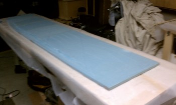
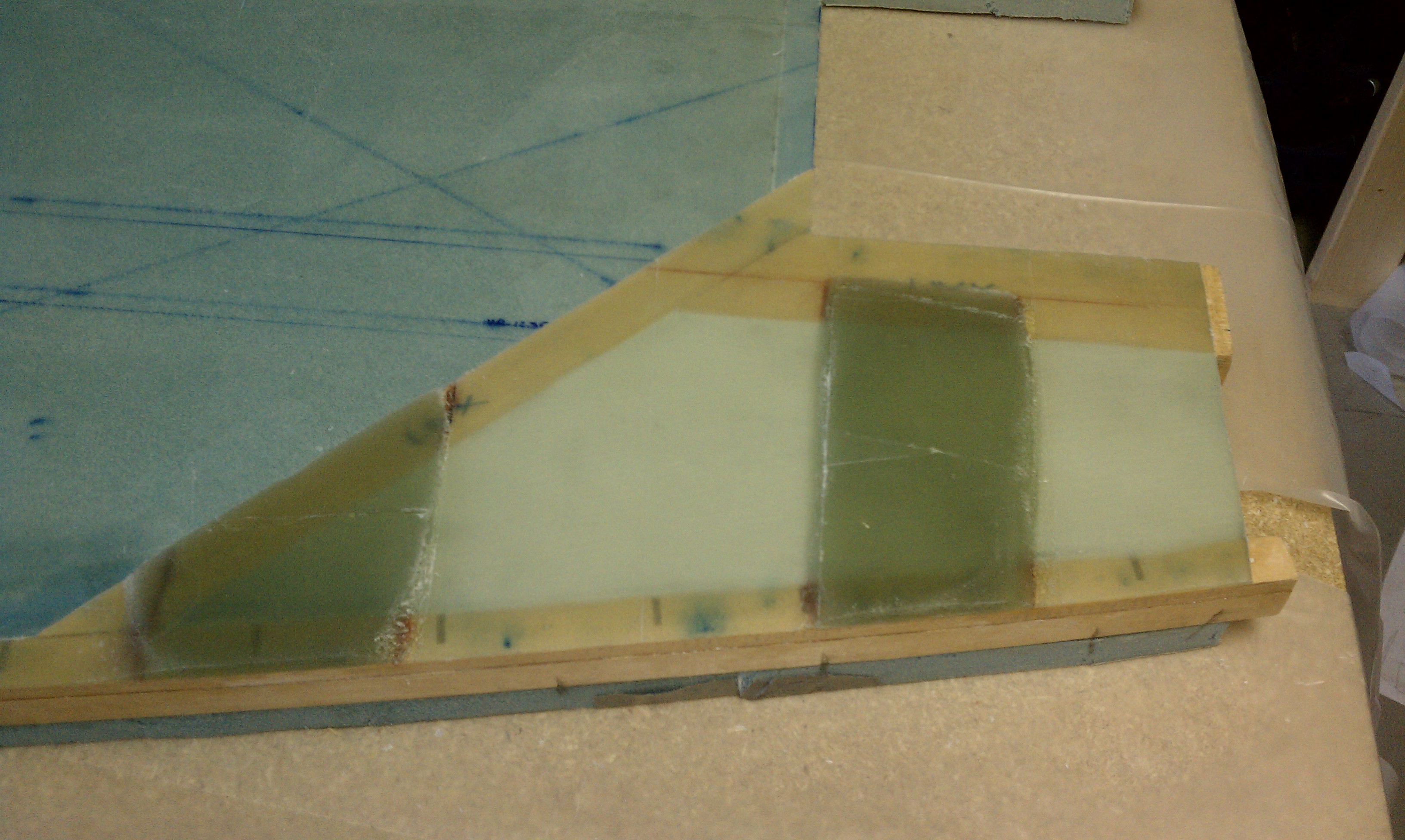
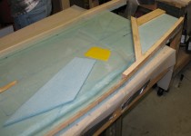
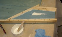
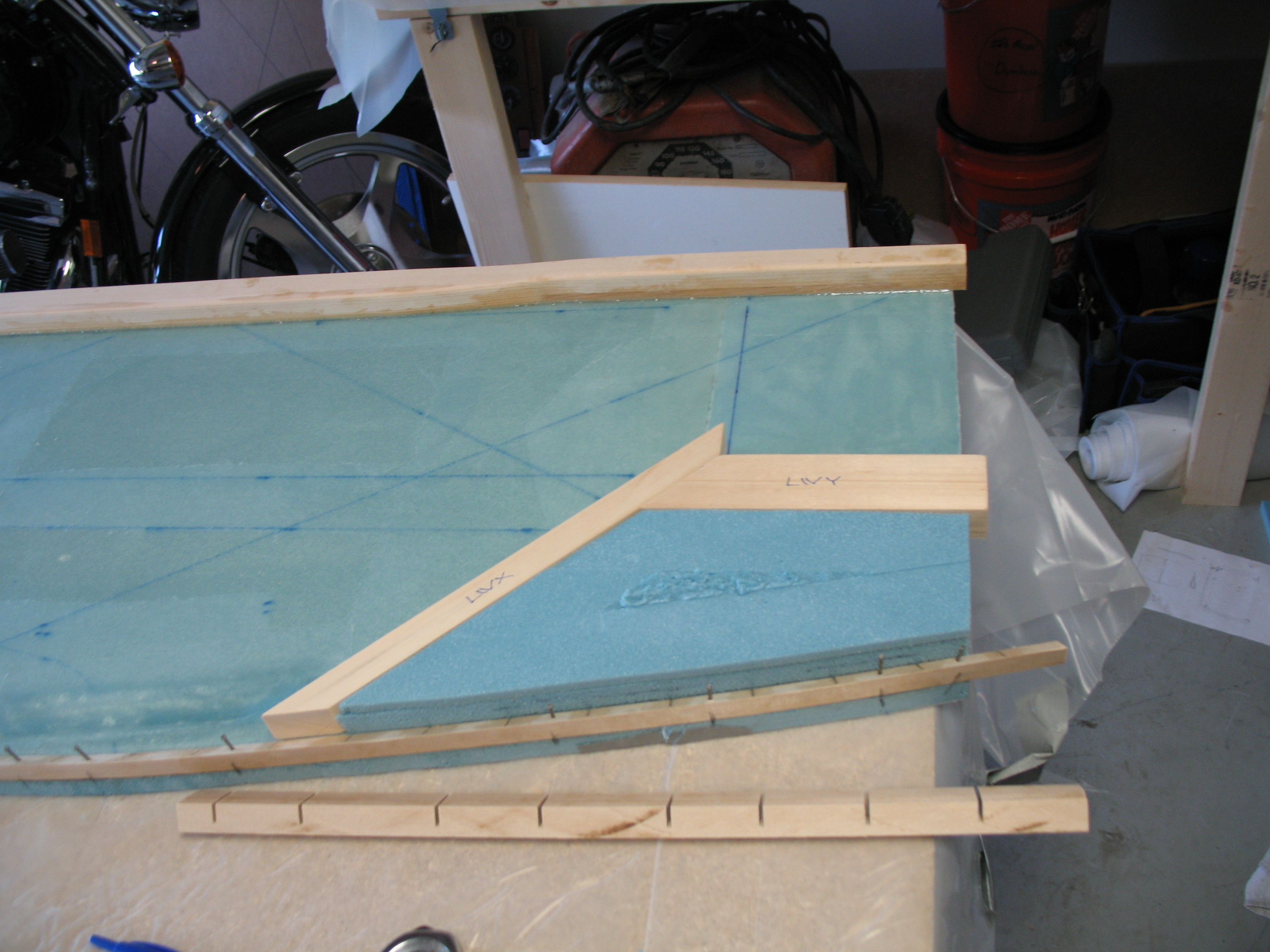
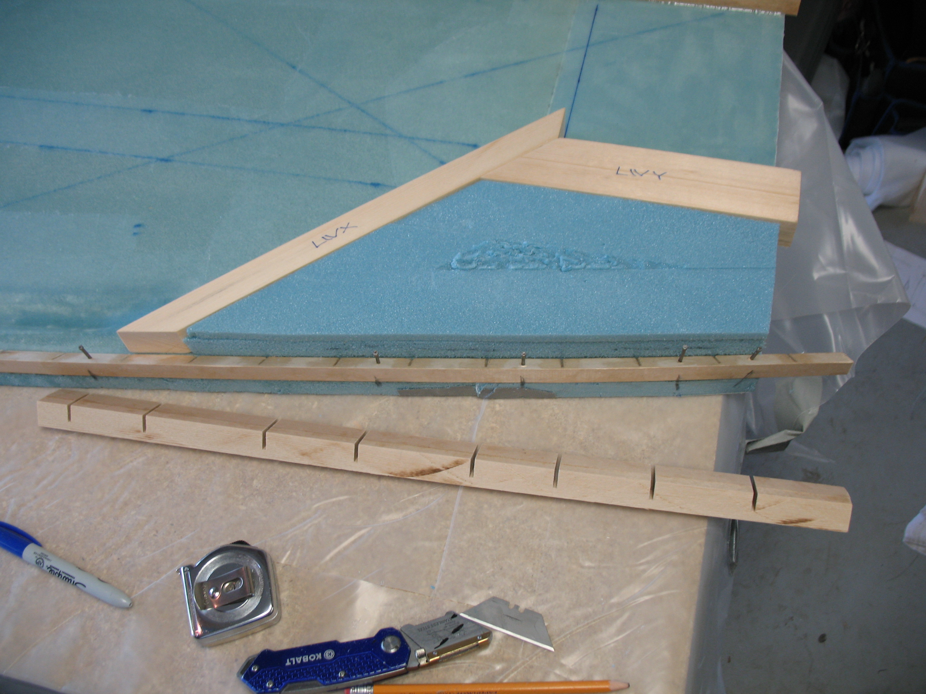
This post focuses on the Main Landing Gear Mount Area that is bordered by the angled LWX to the front, LWY to the top and a doubled angle-to-angle triangular stringer along the bottom.  Although the plans call for Urethane foam (yellow and easily formed) I opted to put the denser, stronger blue Divinycell (same as fuselage sides) in the open filler cavity, in-between all the border Spruce pieces, even though it’s more difficult to work with.  The first pic below shows a foam wedge already in the fill space with another foam fill piece ready to be micro’d in place into the open space remaining.  The second pic shows the foam fill piece micro’d in place and micro being applied to the top of the foam in prep for glassing.  Also, note the flox filling in the gaps that were left by the saw blade, required to bend the Spruce stringer to follow the bottom contour of the fuselage.

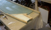
The next set of pics below shows the open space of the main landing gear mount area in the lower rear corner of the right fuselage side filled with foam and ready for glassing with a layer of micro across the foam.  In the second pic, you can see the F28 Bulkhead doubler being mocked up and test-fitted near the front of the fuselage side.

Chapter 5 – Build-out of Right Fuselage Side

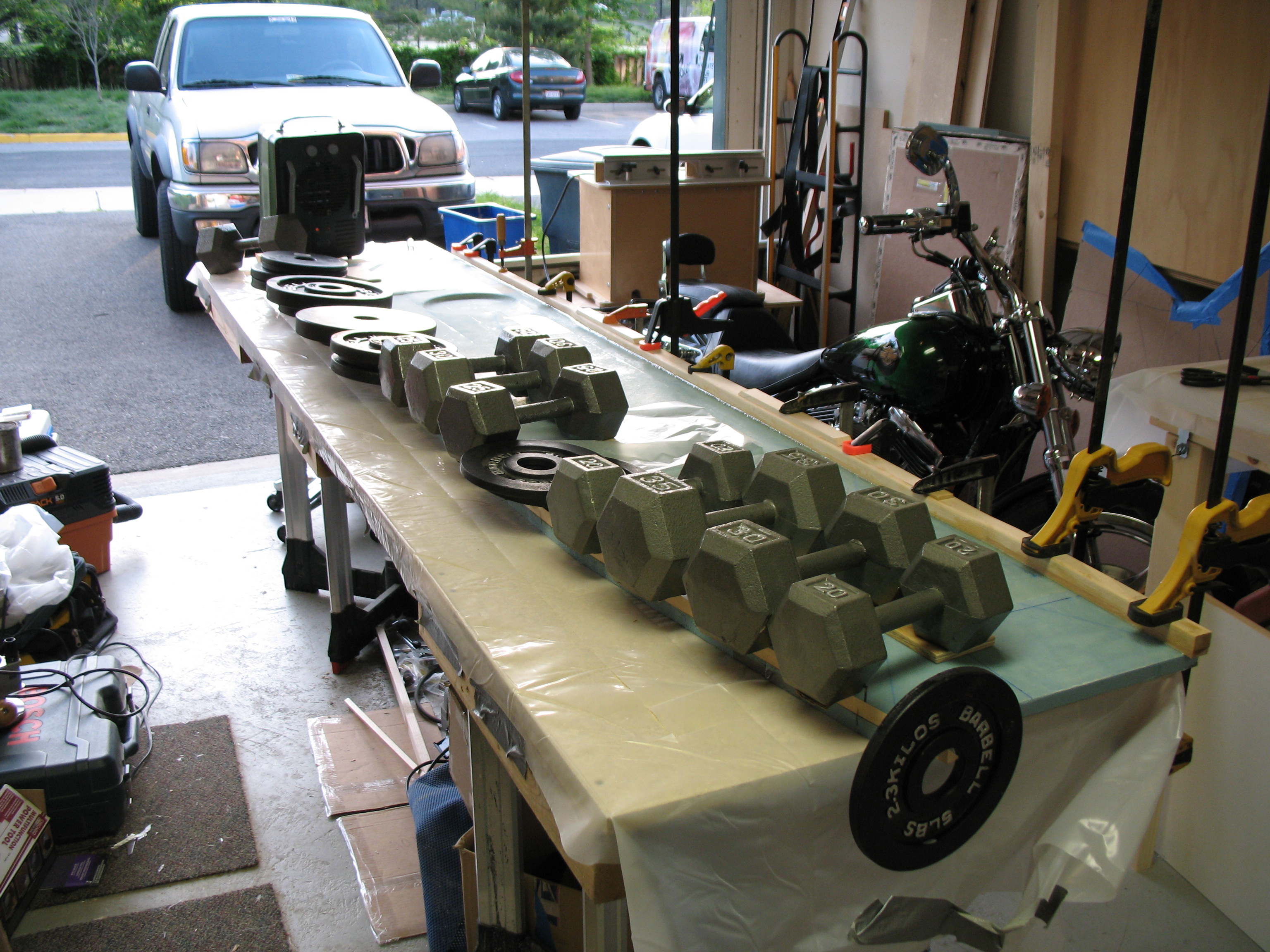
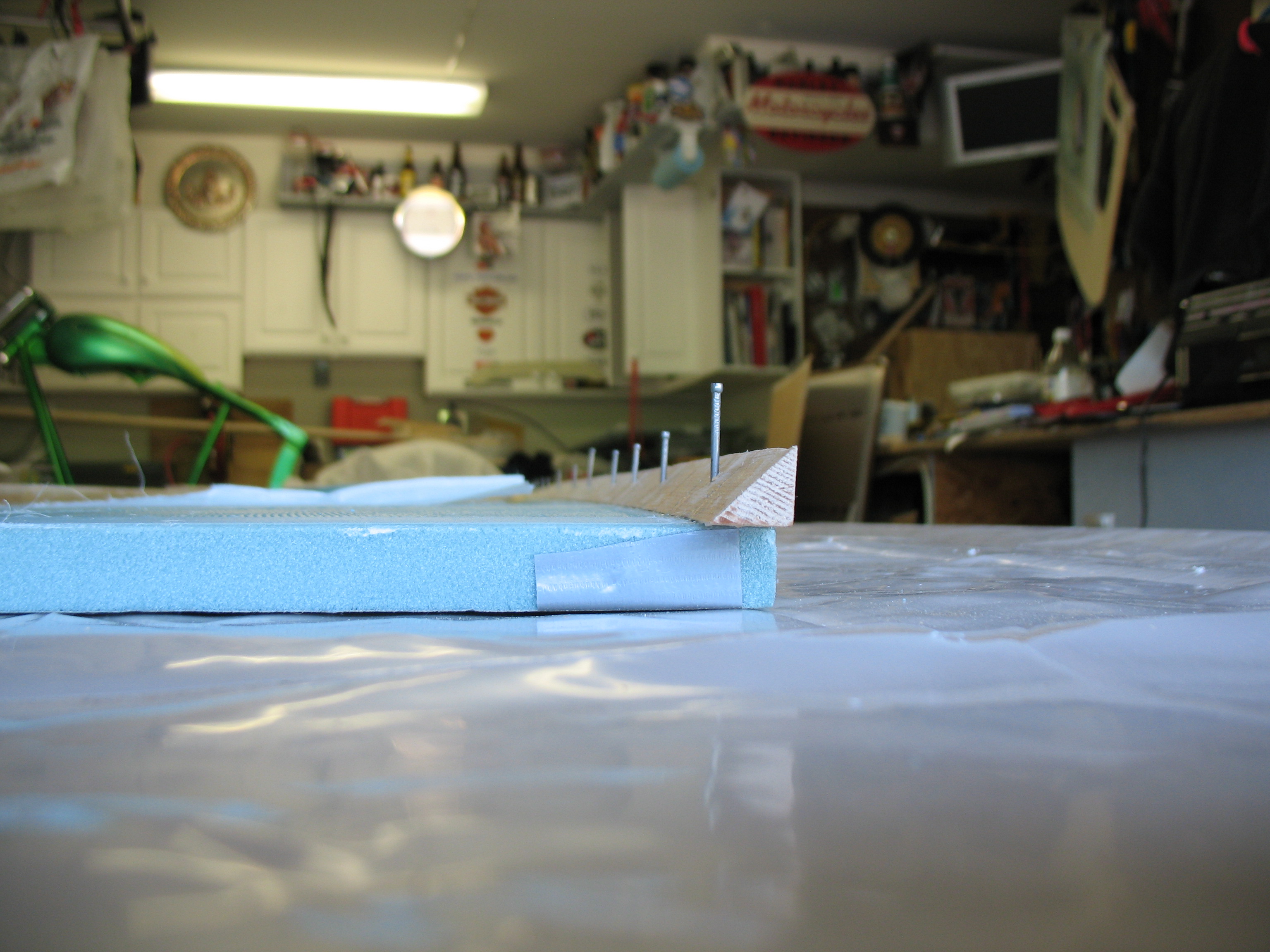
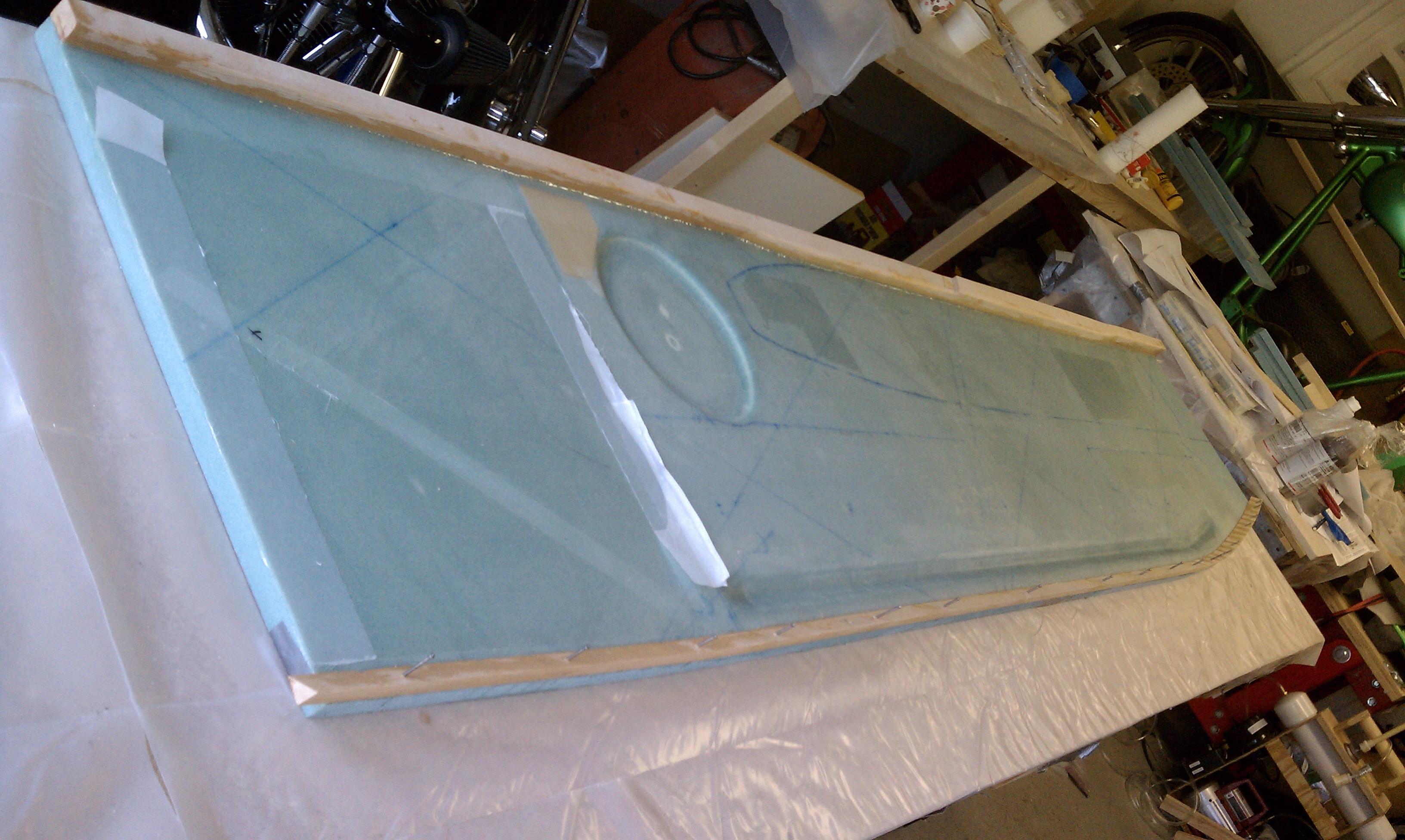
Today I attached the bottom triangular stringer (or longeron) to the bottom edge of the right fuselage side.  Since the bottom of the fuselage is curved, then of course the stringer must be curved as well.  To do this, as per plans, I made a series of cuts approximately half-way through the Spruce stringer.  I then drilled holes through the stringer, the fiberglass and the foam to enable holding the stringer in place with medium-sized finishing nails.  Once I knew the stringer was lined up correctly and matched the fuselage side’s bottom contour, I floxed the stringer to the fuselage side wall and held it in place with the nails.  To ensure the most effective bond with the least amount of excess flox (excess=weight=bad), I weighed the stringer down with weights to squeeze out excess flox, as you see in the pics below.

Right Fuselage Side - Longeron & Stringer Floxed in Place

Below is another close-up end shot of the stringer—more of the nail placement actually—and a couple close up shots of the trial fitting of the LWX & LWY hard points.