Chapter 25 – Paint & pinholes

Today wasn’t a big work day on the build since I had my little buddy with me a good portion of the day.

I was able to wet sand the surfaces of the white nose gear components with 350 grit sandpaper before prepping and then applying another coat of white paint.  This time I used a bit more paint and what was supposed to be a higher quality foam roller, but I still ended up with a myriad of little air bubbles on the paint.  Note that while a majority of boat paints need tipping with a brush, this system supposedly doesn’t require that.

The finish on these parts is not super critical since they are not located in an overly hi-vis area, so it does allow me to dial in the paint application process while I concurrently knock the painting of this stuff out.  I may need to do some wet sanding and buffing out for these guys, but clearly would like to avoid that on the entire plane’s painted surfaces.

I’ll do some research and make some calls.

I understand these aren’t the greatest pics below…  I actually had my little 12 yo buddy help me mix up some West 410 and fill the numerous pinholes on the bottom cowling.  I originally figured I had spotted about 12 of them, but the final number was well over 20.

I then used the remaining bit of West 410 that was in the cup to add a little thickness to the outside of the RAM air scoop opening on one side, and then fill in a bit more on the inside of the lip about 180º out from the first fill.  I’ll continue my iterative process of filling and dialing in the shape of the RAM air scoop opening to ensure it has “a pleasing shape.”

Tomorrow I plan on sanding down all the gray primered components and applying a coat of white primer to them.

Chapter 22/25 – Electrons & Primer

This morning I finished up a project that I’ve been working on over the last few evenings to insert a Molex connector into the wiring bundle between the nose gear actuator assembly and the P1 CPC connector.  The main wires that run through the P1 connector are the gear actuator motor power wires, the up/down limit switches wires and a slew of signal wires for the gear up/down/transit indicator and warning lights.

The issue was the interface between the P1 connector and the NG30 cover.  In the quest for easy maintainability and access, the question regarding the P1 connector was how to mount it to the inside of the NG30 cover that would then allow for it to be disconnected in an efficient manner when the NG30 cover was removed.

If there were a reliable way to mount nutplates to the corners of the plastic bulkhead flange on the P1 connector, that may have been a potential solution… albeit not the most elegant or reliable one over the long run.  That solution would require having to remove 4 extra screws every time I wanted to remove the NG30 cover.  Moreover, the ability to mount nutplates to the bulkhead flange with the space provided was problematic.

Although I don’t like adding connections into electrical circuits, after literally years of pondering the solution to this issue I decided to proceed with adding a 12-position Molex connector into the wire bundle between the P1 connector and the nose gear actuator motor and limit switches.  This would allow me to separate the NG30 cover from the NG30 by simply disconnecting the Molex connector in a couple seconds (vs a minute+ of removing screws).

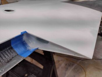
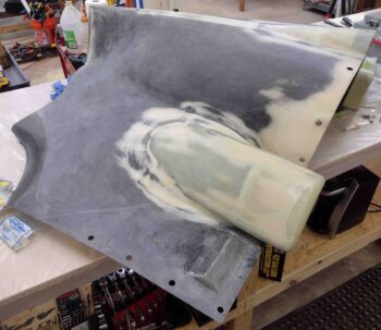
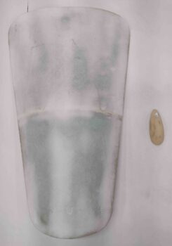
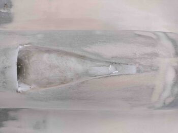
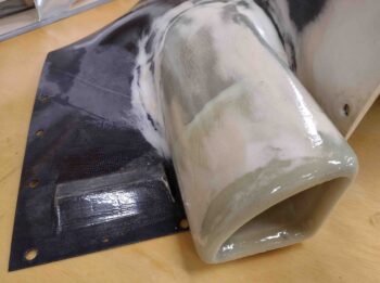
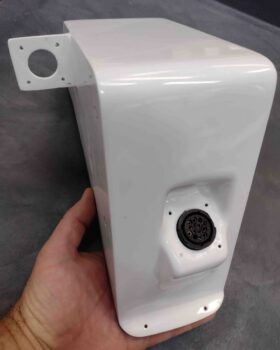
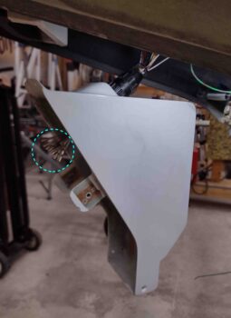
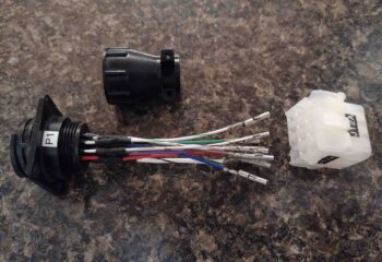
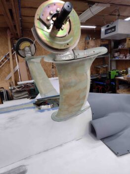
Time has a way of masking problems, and one potential issue I had to check was the fit of the P1 connector into the currently painted NG30 cover.  Thus I had to clean the paint out of the P1 connector mounting hole on the NG30 cover since I haven’t had the two halves of the P1 connector together through the NG30 cover connector mounting hole since after it was painted. Clearly I definitely wanted to ensure that there was still enough clearance for that to work… as you can see here, there is just enough.  It’s tight, but the halves do connect [note the terminated ends of the wires circled in light blue].

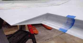
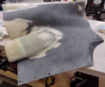
I turned the above pic sideways to show how the external side of the P1 connector will look when the NG30 cover is installed in the nose of the plane.

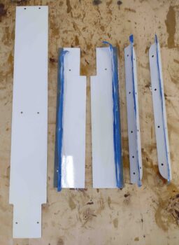
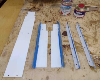
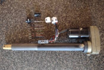
Going back in time a few days, this is how this task evolved.  First I cut the bundle of wires close to the original P1 connector, leaving about an inch of wire hanging off the CPC sockets.  After mapping out the wiring on paper, I then terminated the motor side wire bundle with Molex pins and mounted them inside one half of the Molex connector.

I then had a decision to make: cut and terminate both CPC and Molex sockets onto fresh wires? Or add lengths of wire to the existing 11 CPC sockets and then terminate the opposite ends with Molex sockets?  I chose the latter.

Since I didn’t want to waste any CPC sockets (the power wire sockets are gold plated) I went ahead and simply found the same color wiring in my spare wire bag and soldered these lengths to the existing CPC sockets.  I then added heat shrink to protect the solder splices.

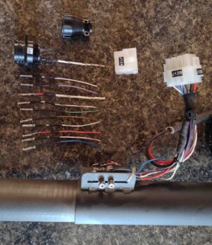
Once the wire lengthening process was complete, I then stripped and crimped Molex sockets onto the ends of the newly added lengths of wire.

I then wrapped the wire bundles in tape, secured them with a zip tie and terminated the sockets into their respective connectors (after performing continuity checks on my work).

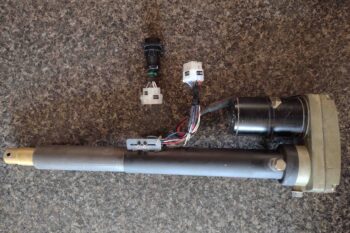
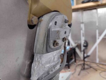
Voila! Here we have the new J12 Molex connector in place on the nose gear actuator.

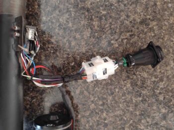
And a closer look at it…. all nice and clearly labeled!

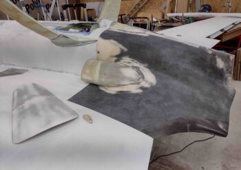
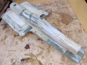
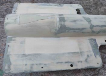
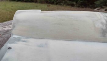
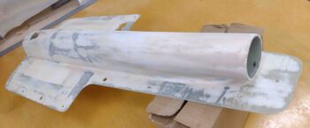
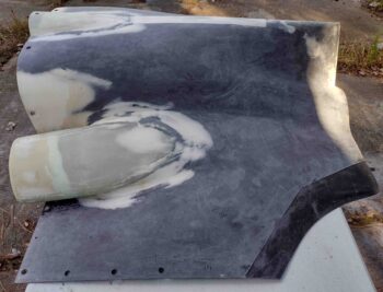
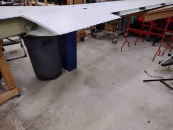
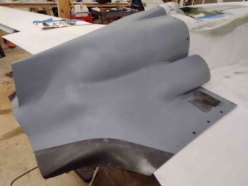
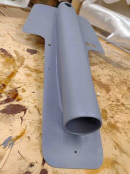
I then went out to the shop and spent a good 45 minutes in final prep on the bottom cowling to allow me to apply thickened (with micro) gray primer.

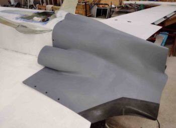
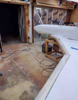
Although I could see about a dozen pin holes on the surface after about an hour into the cure of the primer, I’m extremely pleased with the surface contour and smoothness of the cowling.

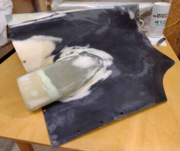
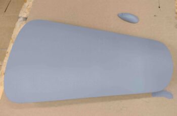
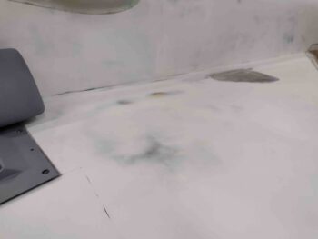
With the same batch of thickened gray primer I also applied it to both the nose hatch door and the belly video camera mount.

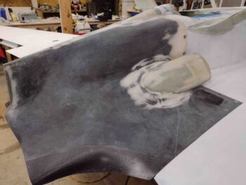
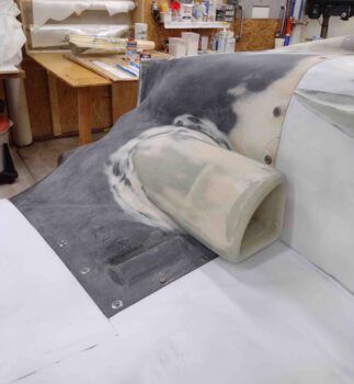
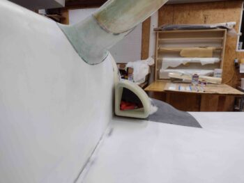
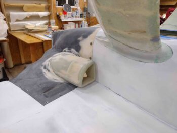
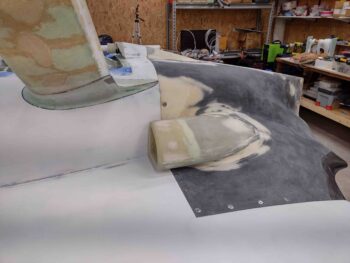
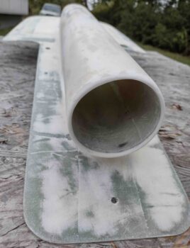
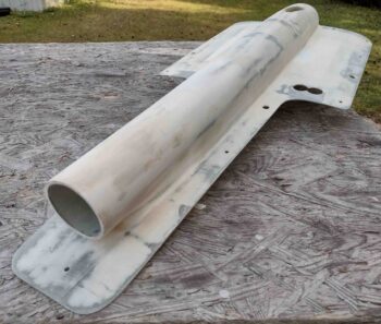
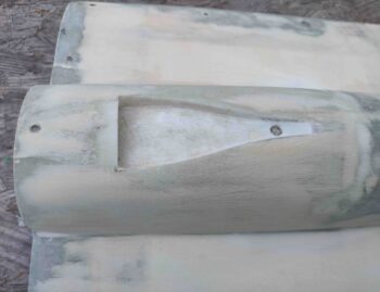
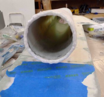
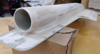
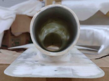
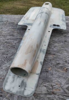
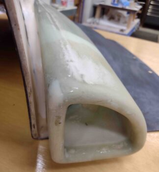
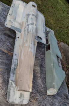
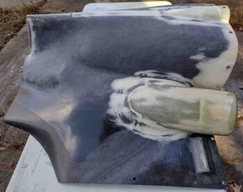
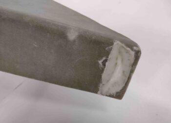
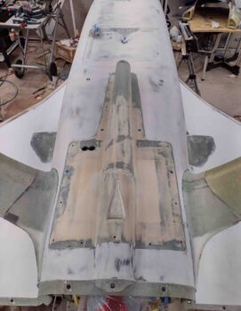
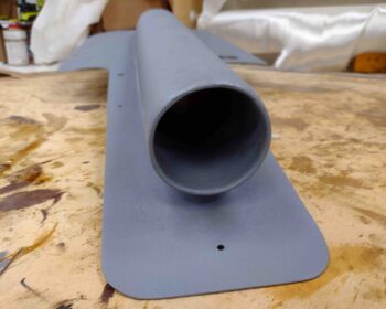
I had planned on applying primer to the RAM air scoop as well, but I knew it would take a while to get it sanded to the final point of being ready for primer… and may have quite possibly needed some refills in areas with West 410.  Thus, I did my first round of primer above, and then got to work sanding the RAM air scoop/hell hole hatch cover for another good hour+.   Thankfully I wouldn’t need any more filler on the RAM air scoop and immediately rolled into cleaning and prepping it for primer.

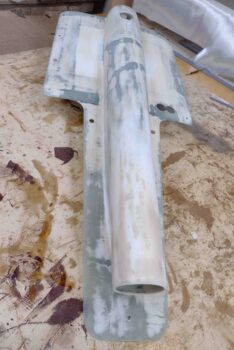
As you can see it turned out very nice.

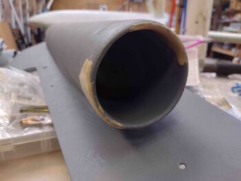
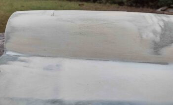
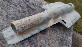
Again, I’m very happy with how the thickened gray primer laid down on the RAM air scoop/hell hole hatch cover.

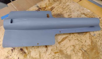
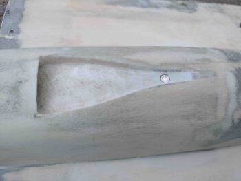
I know I’ll be tweaking the RAM air scoop opening to dial it into as much of an evenly thick, concentric circle as possible… but it’s already looking pretty darn good IMO!

There were actually a couple of tasks I knocked out pre-primer but didn’t get pics of until a bit later.

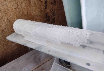
First, I used 220 grit sandpaper to wet sand the thickened white primer I applied to the aft inboard area of the left strake to help clean up some surface irregularities there.  It really came out nicely, although I still have 2-3 minor spots that will need filling before final primer and then paint.

I also removed the right wheel assembly to expose the axle bolts and then allow me to remove one of them to check its length (yeah, I didn’t have the length annotated anywhere…).

Making and installing the inboard brackets to secure the wheel pants not surprisingly caused the axle bolts to be just a hair short.  Turns out that the bolts I had installed were AN4-21As, not the AN4-22As called out for in the plans.  Just another example that if I had followed Burt’s guidance I wouldn’t need to swamp these things out now… ha!

Regardless, I do need to clean up the wheel assemblies and ensure the bearings are nicely packed with grease, so this endeavor shouldn’t be an overly difficult or time-consuming one in addition to my other wheel beatifying duties.

Tomorrow will be a short build day, but I do at least plan to get those pesky pin holes filled!

Chapter 25 – Preppin’ for Primer!

Today I started off by prepping the nose gear strut fairing, the nose gear doors and the nose gear door hinges for white paint.

I then mixed up the white paint and applied it to these nose gear accessories.  I used a foam roller and was a little bit light on the paint, so I believe I induced some air bubbles into the paint surface.  Thus, I’ll wet sand and apply another coat after it cures.

I also painted the outer edges of the aileron pockets —which are already in white primer— since these areas are visible when the ailerons are deflected up and down.

Here’s the inboard side of the aileron pocket.

And the outboard side.  I did this on both wings.

I then spent well over an hour finalizing the sanding of the bottom cowling.  I cleaned up the edges and also redrilled the CAMLOC mounting holes.  I then remounted the bottom cowling onto the plane to double check its fit.

I also knocked out the final sanding in prep for primer on the top nose hatch door and belly video camera mount.

The epoxy wipes of course added just a hair bit of thickness on the front edge of the cowling, so I had to address this and sand down all the edges to ensure the cowling still fit well.

The cowling is a tight fit on the fuselage… nothing egregious or crazy, but I would guess it sits about 0.015″ aft of its original alignment.  It just makes the CAMLOCs fit a little tighter. I would also guess this may loosen up just a bit over time as well.

Here’s a shot of the left armpit air scoop, the gear fairing and the cowling intersection with strake and wing.  I’m happy with all these and so far, so good!

A shot of the the same on the right side.

Here we have a side shot of the re-installed bottom cowling.

After I took these pics, I did do some very minor West 410 refills in a few spots on the bottom cowling.

I also worked a bit more on the shop cleanup/organizing and some electrical work that I’ll report on in tomorrow’s blog post.


Chapter 25 – Why, I love sanding!!

My first task of the day was to knock out the final major sanding of the bottom cowling…

And yes, as always there are few minor things to clean up before I lay down some primer on this beast.

I then got to work on the RAM air scoop/hell hole hatch cover and sanded it in prep for epoxy wiping . . .

Which I rolled right into.  I only did 3 total wipes spaced out about 2.5 hours apart, using West 206 (slow) hardener.

I then did the major sanding on the epoxy wiped nose top hatch door and the belly video camera mount.  I sanded these outside in the dark [with lights on, still not great lighting] and realized I got them both to about 90% done.  I’ll work them both again just a bit tomorrow to finish them up in prep for primer.

And with that, I called it a night.


Chapter 25 – Yup, more finishing!

Today I started off by sanding the RAM air scoop/hell hole hatch cover to pretty much final configuration… and ready for epoxy wiping.

I then went off script for a bit to knock out an ancillary task: the aft NACA scoop ground cover attachment.  I’ve been pondering this for a while, and after learning that my local airport’s schedule to have the new replacement hangars built has slipped again to the summer of 2022 (for the hangars, including mine, that were damaged in a spin-off tornado from hurricane Dorian). Thus, if I finish my Long-EZ prior to next summer –which I fully intend to!– I very well may need to keep my bird parked out on the ramp for a period of time.

In light of this hangar situation, I want to ensure all open holes in the plane are plugged or capped to ensure no bugs or critters take up residence in any aircraft orifices.

I will say that in addition to sealing up the plane during ground parking on the ramp, there is an element of cleaning up the lines when viewed from the side by eliminating the slight “notch” of the NACA scoop on the rounded aft RAM air scoop structure.  See the top vs bottom pics here.

Again, I’ve been pondering just how to attach this NACA scoop cover for a while now.  I finally decided that I would have a rubber/foam type plug that goes into the hole on the aft side, and then a small embedded magnet to keep the front narrow part of the cover attached to the NACA.

Here we have the mounting hole drilled and prepped for a small round embedded magnet.

Since I had these magnets on hand to use for my lathe RPM/tach display, I simply grabbed one for use to secure the aft NACA scoop cover.

After I test-fitted the magnet in its mounting divot, I then sanded the surfaces of the magnet to texture it so that the micro could grip it a bit better.

I then micro’d the small magnet into place in the front channel of the NACA scoop.  You can also see that I added some micro to the aft corners and spots inside the NACA scoop.

I then added a pure flox lip to the front edge opening of the RAM air scoop.  I wanted something that would add strength and durability to anything getting thrown at the RAM air scoop in flight, in addition to being able to be shaped to allow me to create a rounded/radiused edge on the front lip of the RAM air scoop.

I then left the the RAM air scoop and NACA to cure while I spent a good hour sanding the bottom cowling (sorry, no pics).  Tomorrow I’ll press forward with getting these ancillary components prepped first for primer, then paint.

Chapter 25 – More component sanding

I started out today sanding and contouring the last round of West 410 application on the RAM air scoop/hell hole hatch cover.

I’ll admit that my RAM scoop isn’t a perfect concentric circle, but it’s pretty darn close and will work fine for what I need it to do.

Again, here’s another shot of the RAM air scoop/hell hole hatch cover near-final sanding.

That being said, I did need to do a few final/minor touchups with another round of West 410.

I then did another round of sanding on the epoxy-wiped bottom cowling, this time focusing primarily on and around the right armpit scoop.

The biggest challenge on sanding down the cured epoxy wipes on the bottom cowling is the channels on the inner and upper sides of the armpit scoops (in the pic here that would be the left and bottom side).  This effort includes sanding both sides of the channel, which would be the surface of the cowling along with the inside face of the armpit scoop.

In hindsight I should have A) only did 2-3 rounds of epoxy wipes max, and B) sanded the cured epoxy wipes sooner, as I have previously mentioned.

Finally, there is the aft “floor/wall” of these channels, which is the original flange that is floxed & glassed to attach the armpit scoops to the cowling surface.  These are obviously a challenge to sand since the only way in there is to wrap sandpaper around some type of stick or pad… patience and persistency being the rule in sanding all of these internal armpit scoop areas.

Since I’m wet sanding, I do most of my sanding outside.  Well, with the days getting shorter and colder it was darker (even with outdoor lights on) for a good bit of my sanding session.  I did a good 1.5 hours before calling it a night, and as you can see in the pic below I was not able to finish the left side.  This shot gives you a good idea of what the cured epoxy wipes look like pre-sanding.

I did do a fair bit more organizing and cleaning in the shop –well over an hour’s worth– so I’m slowly getting there.  Pressing forward!

Chapter 25 – More filling & sanding

If you’ve been following my build blog you probably have noted a lack of build progress over the past couple of weeks.  I didn’t really report the last few days of my massive shop cleanup, which I’m still on the tail end of, when I then took a few days off to go see the fall foliage rolling in over on the west side of North Carolina in the mountains.

A few days after that I headed out to Kentucky, just a few hours from Rough River actually, to visit my daughter, son-in-law and grandkids for nearly a week.

With a nice respite and a good family visit under my belt, I’m now ready to hop back into the build full bore.

I started off by sanding down the first round of thick “micro” I had applied to the front half of the RAM air scoop to thicken up the front edge to create a nice rounded opening for smoother air flow… think airline engine intake.  I had originally planned on attempting some type of Bell Mouth intake, but realized it would just be too complicated.  Thus, I’m following in the footsteps of fellow builders James Redmon, Dave Berenholtz and Dave Anderson in how they all pretty much constructed their respective RAM air intakes.

After sanding down the first round of filler, I then fine tuned the current filler with yet another round of straight West 410 filler, as you can see below.  I then used some of the leftover West 410 to fill in some of the edges of the glass divot I created on the aft top end of the left pilot armrest that will allow clearance for the fire extinguisher to be mounted on the front side of the pilot seat back just above it.

Another shot of the belly RAM air scoop West 410 refill on the front side of the scoop to thicken it up to allow me to create a thicker, rounder scoop inlet.

I then spent about 3 hours wet sanding the epoxy wiped bottom cowling.  Grant it, I should have done this a few weeks ago since I’m now dealing with a very hard cured West epoxy shell… albeit it’s nice to know how durable this shell actually becomes after a nice bit of cure time.

Note the un-epoxy wiped aft edge of the bottom cowling where I will work the interface with the upper cowling.  After which, I’ll then blend in the finishing and finalize it for the bottom cowling.

The real challenge with the armpit air intake scoops is getting down in between the scoops and the cowling to knock down the cured epoxy.  As you can see, I did a good bit of “damage” to the West epoxy wipe, but didn’t get the entire cowling sanded.  I figure I still have another 2-3 hours left to get this thing sanded in prep for primer… I’ll make another good attempt at it tomorrow.

I will also note that I would sand for a good bit, then take a break to clean up some of the shop before resuming sanding again.  All in all I probably put in a good hour and a half of shop clean-up during these sanding efforts.  Tomorrow looks to be a good deal of rinse and repeat.

Shop cleanup continues

The shop cleanup continues…

Yes, as I noted before, the time had finally come to get the shop cleaned up and organized.

Since everything in the shop is covered in micro dust, I’m removing just about every item, cleaning it and either placing it back into the shop in an organized fashion, or relocating it to somewhere outside the shop.

One big task I was able to accomplish was to get my carts situated so that they are now finally in use for what I bought them for: the white work table for glass work and the black cart for machining items . . .

And I finally got all my sanding boards and sandpaper wrangled in one place in the red cart, with the gray cart used for tools.

You can see in the pic above that I still need to clean off the big worktable and organize the current items on top of it, as well as the far workbench as well. I’ll also populate my pegboards and get tools, etc. organized and hung up.

I’ve been working on this cleanup for a good 8 hours a day for the last few days and figure I have at least another good 8 hours left to finish up this cleanup.

This should be the last major shop cleanup and organizing before I finish this bird.

Chapter 24 – Massive shop cleanup

Before I got started on my massive shop cleanup for the day —again, to facilitate as clean as possible application of paint— I wanted to get at least one actual build related task knocked out.

The micro and glass inlay on the notch I created —to allow clearance for the bottom edge of the fire extinguisher— on the very aft end of the left pilot armrest was one of those small nagging tasks that has needed to be done for quite a while now… so I whipped up some micro and filled in the somewhat jagged foam edge, then applied a ply of BID into the notch on the top side and a small BID patch on the bottom side to lock the top BID ply in place and add just a skooch of strength.

I then set this layup aside as I got busy on cleaning the shop.

Although it may not seem like it if you were to be standing in the workshop, but I spent nearly 8 hours today cleaning and organizing the shop.  Just about anything that could be moved was taken outside and either wiped down or blown off with the air hose —usually both— to remove all the dust… most of it from sanding down the micro finish on the bird.

Not only did I sweep the floors to get all the dust, dirt and debris removed, but after the front 3/4 of bay 1 & 2 were swept, I then started at the back of the shop and blew out all the remaining dust with the high pressure air hose.

Of course after sanding the copious amounts of “micro” finish on the bottom of the fuselage, nose, strakes and wings, there was a LOT of micro dust on the shop floor around the plane.  I’m happy to report that it is all gone now.

That being said, I still have at least another full day of cleaning and organizing to both get the shop cleaned, organized and optimized for not only the upcoming painting, but also the remainder of the build.

I finished my cleaning and organizing tasks at 2230 and called it a night.  Tomorrow will be a lot more of the same… charging forward!

Chapter 24/25 – RAM scoop final steps

Today was about working on 2 things:
1) Trimming the belly RAM air scoop and “micro” finishing the scoop
2) Cleaning and organizing the shop

I started by temporarily installing the RAM air scoop/hell hole hatch cover onto the fuselage.  With the RAM air scoop in place I then marked and trimmed about an inch off the front lip/entry of the RAM air scoop.

I then whipped up some flocro and applied it thickly to the front section of the RAM air scoop and set it aside to cure.

I then spent well over 4 hours cleaning and organizing the shop, since not only does the shop really need a good cleaning in general, but I really need to get the micro dust eliminated as much as possible to proceed with my painting tasks.