Chapter 21 – Sump access ports

Today I started off by sanding the internal foam edges around each sump tank access port hole.  Since the sump top is angled and slopes down almost immediately from the front sump wall, I want to get the sump access port covers configured so that they are as level & parallel with the aircraft’s waterline (0°) as possible.  To do this means that the foam around each opening is actually shaped so that on the top side (remember, I was working on the bottom side of the sump top foam piece) the foam is low on the forward side of each opening and as high as possible in the back.

To prep the inside foam for glass, I simply reversed what will be seen on the top with the front side getting a slight depression –in preparation for the 0.040″ thick nutplate ring– and the aft side getting a much deeper depression, when inverted, meaning that it will place the nutplate ring nose side low and tail side high.  Exactly what needs to happen to get the access port cover as level as possible.  I spent well over 1.5 hours sanding & shaping the foam around each opening (and my aching shoulder can confirm that it was that long!).

Since I’m meeting friends early this evening for dinner, I wanted to ensure I got all the noisy stuff for today’s build out of the way as early as possible.  I loaded up a new bit on my Saber saw and cut out the 2 nutplate rings out of 0.040″ 2024 aluminum.  I then spent a good 5-10 minutes on each one cleaning up the inner & outer edges with a file.  Of course cutting them with a Saber saw meant they didn’t come out perfect, but they certainly meet my requirements and will do the job fine.

I then matched each ring up with a port cover plate as best they aligned and then taped them together with clear packing tape.

I then used my paper template and marked the 7 screw holes on each ring.  I then drilled out the screw holes to attain a spot-on alignment between each nutplate ring and cover. To ensure I didn’t get the cover plates or sides mixed up, I used a scribe to place a small “A” on one set, both cover and ring, and a “B” on the other.

I then pulled the protective film off all the aluminum, set up a screw to show the alignment between cover & ring, and then set a number of the covered nutplates in their positions to provide a general idea of how these pieces work & go together.

Tomorrow I’ll Alodine these aluminum pieces and glass the internal side of the sump top cover.  I’ll then rivet all the nutplates to the sump access port cover rings.  Since E-Z Poxy needs a good cure, I won’t really get to glassing the sump top in place until either Sunday night or Monday.


Chapter 17/21/24 – Chapter 17 complete!

Well, I have to admit that when I started off this morning by using 5-min glue to mount the fuel vapor sensor module’s clickbonds in place, I realized I have may have been a bit too thick with the praise for MGS over E-Z Poxy when it comes to mounting clickbonds, since I do quite often use 5-min glue to initially hold them in place.  However, I will still state that I have not had an issue with either 5-min glue or MGS when it comes to clickbonds.

Moving on.  I prepped the bottom of the fuel vapor sensor module with clear packing tape, then put some dabs of 5-min glue on each prepped clickbond and set it in place.

A bit later I laid up 2 plies of BID over these clickbonds and then peel plied the layup.

Today I also finished drilling & countersinking the rivet holes for the nutplates that will eventually get mounted onto the armrest (etc.) mounting brackets.

Here’s a shot of the drilled and countersunk rivet holes in the mounting brackets.

I then Alodined the armrest mounting brackets and the FT-60 Red Cube fuel flow sensor mounting bracket.

I then riveted the 90 deg. corner -4 nutplates in place on the FT-60 Red Cube fuel flow sensor mounting bracket.

Here’s a shot of the bottom side of the bracket (my Alodine is a bit old, and unlike a fine wine it doesn’t get better with age… maybe that explains some of the splotchiness on my bracket… not sure…)

And here is the  FT-60 Red Cube fuel flow sensor mounting bracket after I floxed ‘er up and bolted ‘er in!

I then got to work on the Roll Trim mounting pad.  I had ordered K1000-06 nutplates for the 6-32 screws that will be used to mount the RAC servo to the fuselage sidewall.  Well, I had a “Doh!” moment when I realized that since the RAC servo has corner mounting holes, I should have ordered 90° corner nutplates.  Oh well, since the Roll Servo is fairly light and in normal ops not an overly used device, I made a command decision that one rivet tab would do to hold each nutplate in place on its respective G10 Garolate nutplate base.

[Note: Normally this servo would get mounted straight to the sidewall, but since I had to kick in my control tubes about 3/4″ inboard to allow for the CG controls, I am simply “extending” the fuselage sidewall inboard 3/4″ with this foam base]

Once I got all the nutplates riveted to their 1/16″ G10 base, I mounted them to the RAC servo and figured out their exact location in the foam.  I then notched the foam at each corner and embedded each nutplate assembly.

I then taped up the bottom of the RAC servo to use it as a guide, and then mounted the nutplate assemblies back onto the servo.  I then micro’d up the bottom of each nutplate assembly and the corner notches in the foam.  I set the nutplates (with servo) in place, and once satisfied that they were all in the right position, weighed down the servo to press the nutplates into their respective notched corners (I failed to get a pic prior to this of having shaped the edges of the foam to allow for glass transition to the fuselage sidewall).

Later, after it all cured, I filled each nutplate with plastic/saran wrap to keep the micro out of the nutplate threads.

Later still, I prepped the foam roll trim servo base with micro and micro’d it to the right fuselage sidewall just aft of the pilot’s seat.  I then laid up 3 plies of BID over the foam base and then peel plied the edges with 2″ peel ply tapes.  I double checked the elevation a few times using the RAC servo with the spring push/pull assembly attached.  With only a few minor tasks left, like drilling the screw holes and pulling the protective plastic wrap out, I’m calling Chapter 17 – Pitch & Roll Trim Systems, complete!

Tonight I floxed in 3 mounting tabs that were screwed to the GIB left armrest.  These are 3 of 4 tabs that are located primarily on the aft side of the armrest.  I’m planning on building a small framed mounting bracket that will be used to also house the GIB headset jacks and PTT button on the front side of the left armrest, which will have a nutplate attached to it and be the 4th mounting tab.

In addition to the left side armrest, I also added another mounting bracket to the GIB right armrest by floxing in place a tab on the aft side of the armrest where it meets up with the seat back.

Tomorrow I really do plan on working on the fuel sump top, but will be going out to eat with some friends so it won’t be a completely full work day.


Chapter 21/24 – Bit here, bit there

I started out today wanting to get the FT-60 Red Cube fuel flow sensor mounting bracket finished so that I could Alodine it with the armrest mounting brackets that I planned to prep as well.  Well, I went as far as I could before having to get on the road to head up towards the Dulles area to help out a friend.

I did get the FT-60 bracket configured with the mounting bolts drilled and the corner nutplates’ rivet holes drilled out as well.

I countersunk the rivet holes in prep for using flush rivets.

Thankfully, after the click bond disbonding issue, I was able to get the bolt holes aligned correctly, since the Red Cub sits on its bracket at a slight angle left-right to align properly with the fuel feed tube.  I added the nutplates in the pic so you can get a sense of how it all goes together.

Also, after pondering it for the last day or two I decided that with all the fuel lines, fittings & components in the back seat area –and the entire cockpit actually– that the fuel vapor sensor that I bought while I was in Qatar was going back into the lineup.  I just think that it’s the prudent thing to do to have the earliest possible warning of any fuel leak, at the vapor level before it gets any bigger/worse.  I decided on an out-of-the-way spot for the sensor element and will mount it there (it’s just mocked up here) with 2 click bonds using?! . . . yep, MGS!

I know I stated in my video that the sump top was the next item to be worked, and I have been (slowly) working on curving the top cover of the fuel sump by heating it up.  I have never undertaken the curving of foam by heating it up, as the plans references a few times for curved foam parts.  The feedback that I’ve seen on this method has not been good, and most people generally cut relief grooves and curve the foam that way.  I wanted to try it simply out of curiosity.  It does work, but there is some inherent problematic issues in heating it up to curve it.

First, I started off trying to simply use the fuel sump as the form and set the lid foam on top of it.  I then weighed it down and heated it up in place there.  I thought there might be some issue with some spring back after I removed the foam once it cooled, and I was right.  With that knowledge in hand, as well as some nice scrapes on my fuselage floor from heavy weights leaping off the tricky curved sump surface, I decided to shape the foam off of the actual sump.

Next, to get an even curve, I used a 1×4 board base as I weighed it down with weights with the top set upside down against a 4×4.  Well, the end result was angled curves with “corners” somewhat like you’d get with a hex shape.

No big deal, but it is something I’ll have to contend with.  I’ll keep working the top sump cover as I finish up these smaller sideline tasks for the time being.

Finally, I spent a good couple of hours working on my last batch (hopefully!) of mounting tabs for the GIB left armrest, as well as backfilling some inventory that I stole from the front & aft right side armrests.  Over the next day or so I do intend on getting the GIB left armrest mounted, as well as getting 2-3 more tabs mounted on the right side as well.  I did run out of time finishing these up to get them Alodined before installing them, so I will work to get this batch knocked out tomorrow.

After a not so productive weekend as far as the airplane build is concerned, I’m hoping for a very productive week!


Chapter 17 & 21 – Boo E-Z Poxy!!!

Ok, obviously I have no hard facts or empirical evidence here, but after some cleanups and just general workings with E-Z Poxy, I have to say –or rather my gut says– that E-Z Poxy is just not as strong as MGS.

Case in point.  Yes, this may just be an isolated, one-off chance incident, but in the myriad of click bonds that I have used in my build thus far, I have always given the threads a good wipe down after I layup the glass over top of them, and then after it cures I use a thin standard nut to clean up any small film of epoxy from the threads.  I start the thread on, and analogous to tapping threads, I tighten it till it gets firm, give it a little extra push, then back off.

I’ve never had an issue cleaning the threads this way until I hit my first click bond that I used some leftover E-Z Poxy flox to mount the 3 click bonds for the Red Cube mounting bracket.  As soon as I got to that first little oomph, I could tell the click bond snapped free of its bonded base.  Of course, then I didn’t have a good way to get the nut off since the base was spinning feely!  After messing around with it for a bit, I simply used my Dremel cutoff tool and ridded myself of the useless post & nut.  For the next 2 click bonds I was of course much more cautious, gentle and moved much slower, grumbling and NOT happy with E-Z Poxy the entire time!

Coincidence?!  Maybe so, but this builder will never find out because I’ll simply stick to MGS from here on out.  Thus, my cool 3 click bond posts for the Red Cube mounting bracket are now simply 2 posts, and I’ll flox on the mounting bracket for extra measure when it goes on.  Since these sit on the fuselage layup for the main landing gear mounting brackets, I’m not messing around with digging that click bond out or redoing it…. I just won’t chance doing more damage to some very critical fiberglass.  I’ll just chalk it up to being in the aptly named “Hell Hole” and move on . . . with lesson learned in hand.

With the MGS epoxy that I used for laying up the BID over the fuel pulsation damper Adel clamp and red cube mounting bracket click bonds, I also had whipped up some flox to mount the slightly undersized threaded rod of the lower roll trim spring assembly into the RAC servo’s clevis.  I forgot to get a pic yesterday, but here it is today nice and cured.

I had planned to do much more but messing around with the kaput click bond burned up the time I had since I had to take off mid afternoon to see some friends.  Tomorrow will be essentially a non-build day so I’ll get back to it Monday, although Monday late afternoon I’ll be helping a friend with some stuff . . . so also not a full build day!


Chapter 21 – Fuel Lines Complete!

Today I started out by pulling the peel ply off the layups from last night.  I cleaned up the peel ply edges on the 1 ply BID that I used to cover the right main tank fuel sump feed ‘alcove.’  I did have to spend a good 20 minutes on cleaning up the opening of the fuel tube because my protective tape didn’t stick so well and left some untoward flox in places it was not supposed to be.  Fun.

I then got ready to flox the main tank fuel feed lines into place at the top forward edge of each sump sidewall.  I cut & sanded the troughs in each wall to accept the tubing, but before I could proceed on the right wall, I needed to mount the fuel pulsation damper in place to avert a more difficult install later on.

I actually went back upstairs and brushed up a bit on installation techniques & methods before diving in.  Also, on a FaceBook post a few weeks back, Nate Mullins stated that he had used DEL fitting seals with very good results, and since I was getting ready to submit an Aircraft Spruce order, I put them in the basket…. talk about good timing, eh?!

Here’s a closeup of a DEL fitting seal.

After getting the pulsation damper mounted, along with the fuel line traveling aft from it to the engine (via the FT-60 ‘Red Cube’ fuel flow sensor), I then floxed in place the main tank fuel feeds to each sump tank & the sump vents.  After I got the flox set where I wanted it, I then peel plied it to match the top edge of the side walls fairly closely.

In addition, if you look closely in the pic below, you can see that I floxed a Clickbond in place for the fuel pulsation damper Adel clamp.

Here’s a shot of the left fuel line feed into the sump along with the fuel sump vent.

And here’s another shot of the right fuel line feed into the sump and the fuel vent.  Also note that the engine fuel line feed is now permanently mounted.

With the leftover flox from mounting the fuel line feeds in place, I marked up the left GIB armrest with 3 attach points.  I then marked the mounting hole locations of those 3 attach points, hollowed out the foam to create a hardpoint divot at each spot, and filled it with the leftover flox.  I also did one more hardpoint in the same manner on the aft side of the right GIB armrest [no pic].

I then spent a bit sanding down the aft sump 1-ply BID layup that I put in place by utilizing a dam.  The corners especially needed a bit of work, but after some diligent sanding I finally dialed it in.

I then prepregged 1 ply of BID and laid it up after filling a few holes with micro.  This layup completely covers the glass dam that I laid up before, and overlaps onto the fuselage floor (GIB seat pan) by an inch.  I then peel plied it and slathered a bit more with E-Z Poxy to ensure the layup was good & wet.

I then cleaned up, pulled my wings back inside the shop and called it a night.


Chapter 21 – Main fuel tank lines

Today I started on the right main tank fuel pickup port by marking it up & then cutting it out.  I then shaped the foam on the inside of the fuel pickup port ‘alcove’.

I then marked the inside of the fuselage where the right main tank to right sump feed line will enter into the fuselage.  The point on the right side is much higher than the left making the amount of fuel line tubing having to traverse through the sidewall much less than on the left, so the process was significantly easier in running this line.

I then drilled and widened the hole to the point it would accept a 1/2″ fuel line.

I also worked on the external side to ensure the 1/2″ fuel line could be routed into place.

Here’s a shot after I routed the right main tank fuel line feed and flared it to create a nice pickup port, and also the 1/4″ vent line that I ran from the sump.

Here’s a shot of the right main tank fuel line feed and the sump vent line (and the engine fuel feed line).

Here’s a wider angle shot showing the right side fuel feed and vent lines to the sump.

I finished up the evening by prepping to glass the right side main tank fuel pickup port, but first I used some micro to secure the left side fuel sump vent line and laid up 1 ply of BID over it.

I then glassed the right side main tank fuel pickup port and the fuel sump vent line.

Tomorrow I’ll continue to work on the fuel sump in attempt to get it knocked out over the next few days.


Chapter 21 – Blog post from HELL!

Usually it’s a layup that can turn south and become the layup from hell, but tonight it was as if all my technology turned against me.  I couldn’t get my Gmail to synch on my phone, so every email with attached pics simply queued up and went nowhere, which may or may not have been associated with me having to reboot my home Internet router a number of times to get it to acquire a network IP address for Internet access.  In addition, I checked earlier in the week on my phone camera’s inability to focus (note that I said “phone”, not me! ha!) . . . apparently in one of Samsung’s latest updates they actually jacked up the camera function.  Their fix is to go as high res as possible on the camera setting, but that still doesn’t resolve the cat ‘n mouse game I’ve been playing with getting a number of these pics in focus. So once again, if the pics are slightly fuzzy, I apologize.

Moving on.

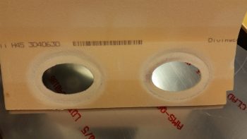
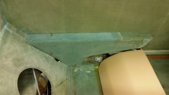
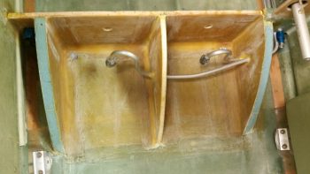
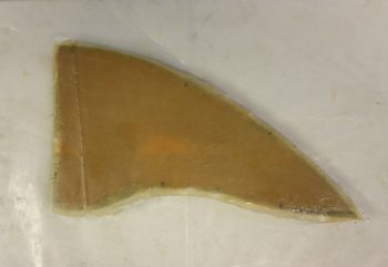
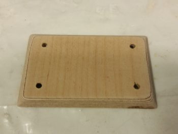
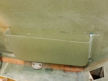
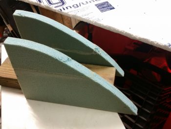
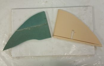
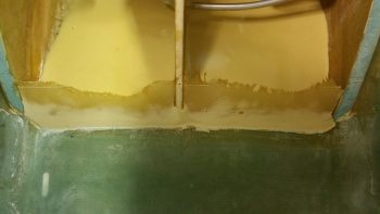
I started off today by pulling off the dam form/mold from the bottom aft side of the sump walls.

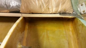
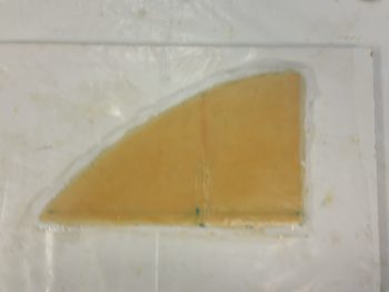
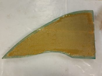
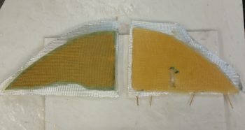
Here’s a closer up shot of the glass layups and micro with the peel ply still in place.

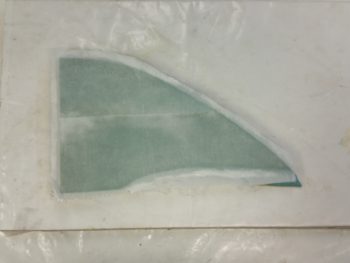
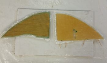
I then pulled the peel ply.

And spent a good while cleaning up the micro junk left over.

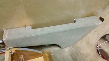
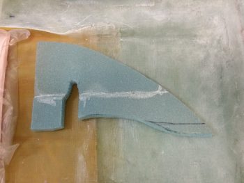
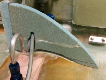
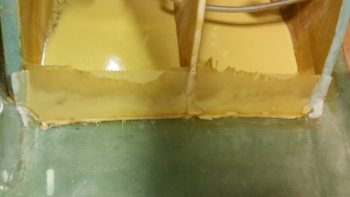
I then aggressively sanded the micro and gunk at the bottom aft side of the sump walls before trimming the glass that creates a mini wall at the bottom aft of the fuel sump.

I then stuck on a new piece of 32 grit sandpaper onto my hardboard and went to town on the upper lip since there was a decent ridge over on the left side that was about 1/8″ higher than the top edge of the sump front wall piece.  I got that all evened out and the lip close to being ready for the future floxing on of the sump top.

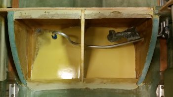
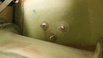
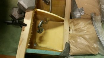
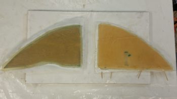
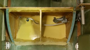
I then ginned up some E-Z Poxy, whipped up some micro and made some corner fillets next to the fuel drain holes to ensure that any water in the sump tanks didn’t shoot past the hole and merely sit in the corner pockets.  This of course is analogous to what is done with the fuel drain on the main tanks.

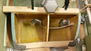
Here’s the right sump tank corner micro fillet.

And the left tank.

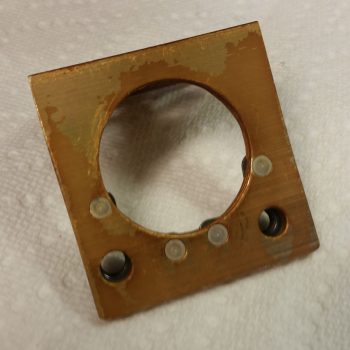
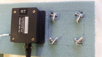
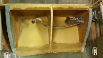
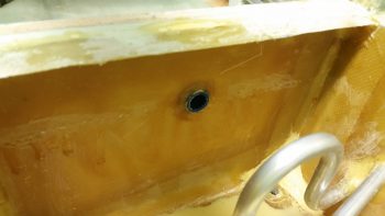
I then used the epoxy I just mixed to make up some flox to install the right low fuel sensor fitting into the front wall of the right sump tank.  I placed each of the low fuel sensors in the center of each tank, both almost 2″ down to keep them from constantly ringing off with false alarms.

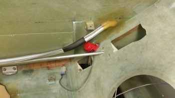
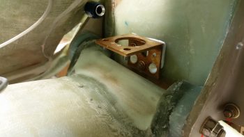
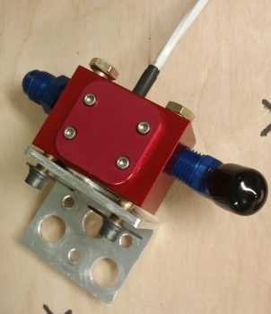
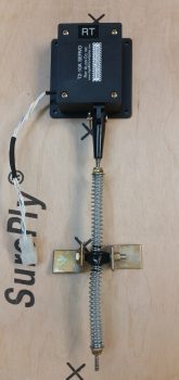
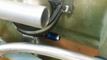
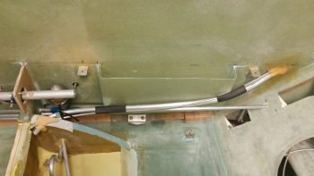
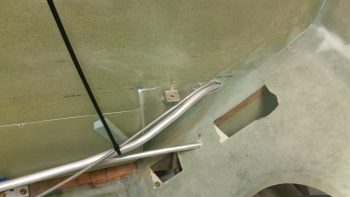
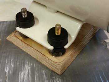
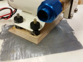
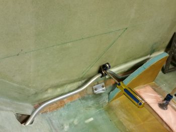
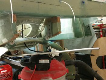
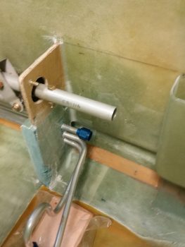
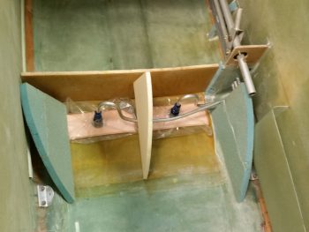
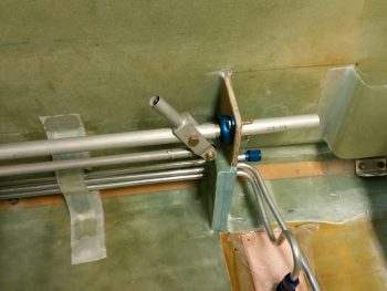
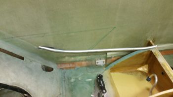
I then set the fuel pulsation damper in position and spent a bit of time dialing in the position and tube bend of the fuel line from the pulsation damper to the FT-60 Red Cube fuel flow sensor.  In a perfect world the pulsation damper would be mounted immediately forward of the red cube, but I just couldn’t get both fitted into one spot with the space I have on hand.  In other words, I couldn’t get them paired together neither where the pulsation damper is now, nor where the red cube is in the hell hole.  For flow requirements for both, this was the best compromise and I believe the damper should still work well to smooth out any odd pulses generated by the system, and allow quicker recovery of fuel flow sensing after the fuel pump is turned off.

[NOTE: Electric fuel boost pumps are known culprits to cause the fuel flow readings to be off while the pump is on… the major drawback of mounting the red cube forward of the mechanical fuel pump, which itself doesn’t cause errant readings and is the preferred mounting (mandated) location of the manufacturer.  I’m mounting it on the cold side of the firewall since it’s way easier, safer (IMO) and besides the jumpy readings only during fuel boost pump ops –which has very minor, negligible affects on overall fuel usage data– works fine according to a large number of our RV building/flying brethren].  

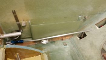
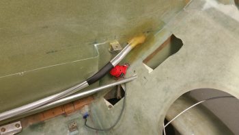
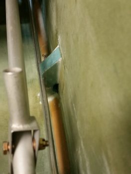
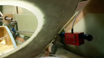
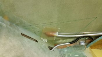
Here’s a shot of the fuel line traversing through the back seat bulkhead and connecting to the FT-60 Red Cube.  Mounting the fuel line through the seat bulkhead this way of course required me to flare and terminate the fitting on the aft side, then after drilling the hole I had to then ensure I bent the tubing just right to intersect & mount to the pulsation damper before flaring and terminating the fitting on the forward side of the seat bulkhead.

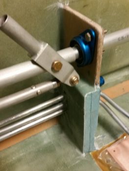
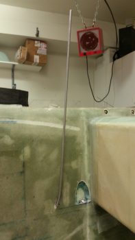
Here’s a shot of the FT-60 Red Cube fuel flow sensor.  It’s hanging in space right now, but once I get a small order that I placed with ACS I’ll have the hardware to build & mount a bracket for it to attach to.  I’ll note that one of the requirements for fuel flow OUT of the red cube is to have the fuel flow upwards (specifically, not “downwards”) to ensure no reading-deviating cavitation occurs.  There should be 5-6″ of straight plumbing after the fuel exits the sensor, but many have reported that a 45° fitting has worked just fine.  With this final location I may very well be able to use a straight fitting and obtain that desired 5-6″ straight line out.  Either way, I think this configuration will be acceptable for good fuel flow sensor readings.

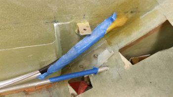
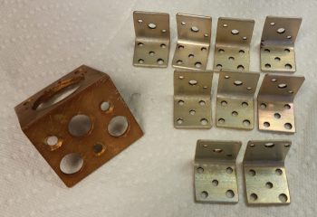
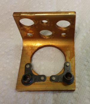
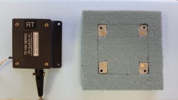
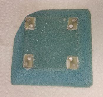
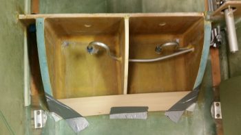
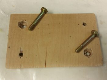
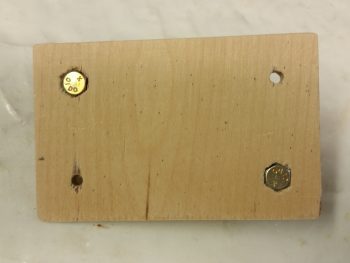
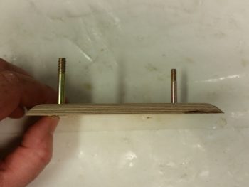
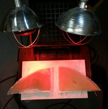
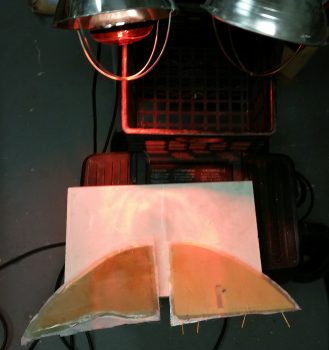
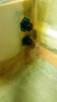
To prepare the left side sump accoutrements before proceeding with mounting the left armrest, I needed to mount the oil heat line reducer fittings in the fuel sump front wall left side extension.  Since I may need to tweak or modify the oil heat configuration at some point in the future, I wanted these reducer fittings “hard” mounted, but not permanently, if you will.  Thus, I used Silicone RTV to keep them in place, and slathered them up and set them in place in their respective mounting holes.

I then went to grab a bite to eat and run to the store while the RTV set up & cured.

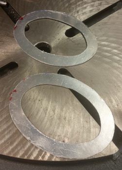
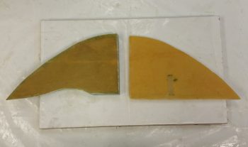
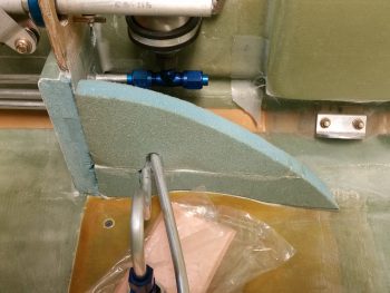
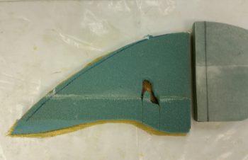
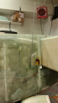
Upon returning home, I marked up the Vance Atkinson designed main tank fuel pickup port to be used in configurations where no external fuel sumps are employed.  The other major design for this type of fuel pickup is from Ken Miller, who calls for a cigar tube shaped pickup that sticks out into the fuel tank right at the fuel tank floor level (both designs have the fuel tank floor foam removed in the immediate area of the fuel pickup port, with just glass-to-glass contact for better fuel flow into the pickup port).  Since Ken’s design calls out for fittings to be used, I opted for the simpler and cleaner (again, IMO) design of Vance Atkinson’s — albeit, to be fair I could have used Ken’s design sans fittings, but obviously went the Atkinson route.

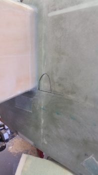
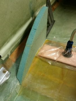
The design for the fuel pickup port, again, is pretty darn simple and straightforward.  It calls for the glass and foam to be removed from the tank side into the sidewall until the interior fuselage glass is reached.  Then a straight bottom “shelf” is created, with an  “alcove” above it for fuel flow.  I determined the top edge of the left fuel tank floor and then marked it.  I then marked up the alcove portion of the left fuel inlet port.

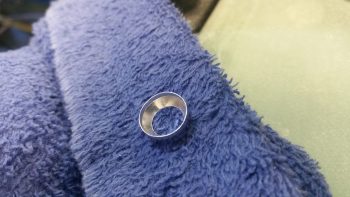
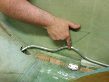
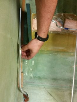
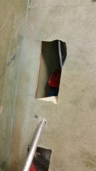
I then spent a good 2 hours of sheer knuckle-busting, finger-slicing pain in getting the 1/2″ fuel line run from the internal side of fuselage up to the left fuel tank inlet/pickup port.  I was then able to coax just enough of the fuel line out to flare it to create a nice pickup funnel affect.

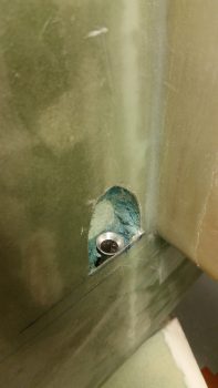
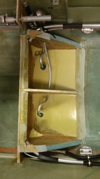
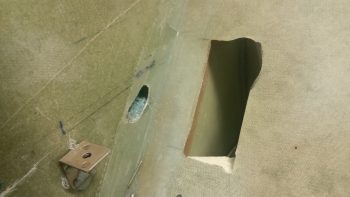
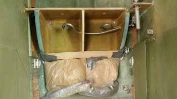
Here’s the interior portion of the left main fuel tank to left fuel sump tank feed line.

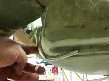
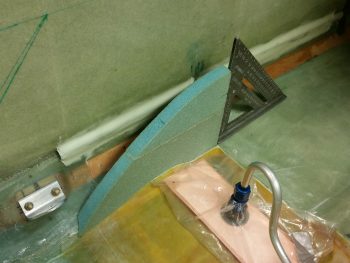
I then went through a smaller version of the pain I experienced before to install the 1/4″ left fuel sump tank vent line from the main tank down to the sump.

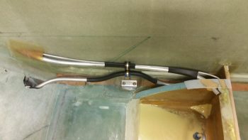
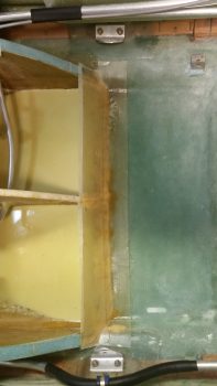
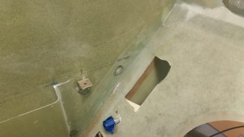
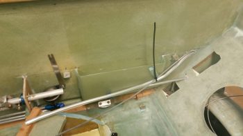
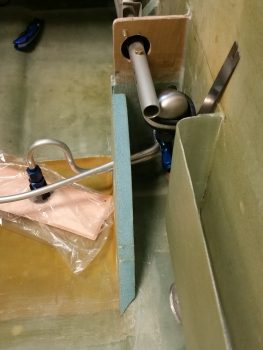
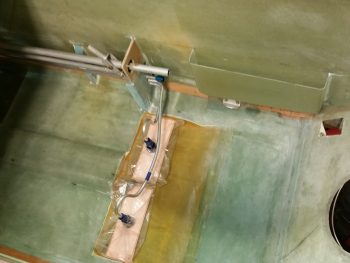
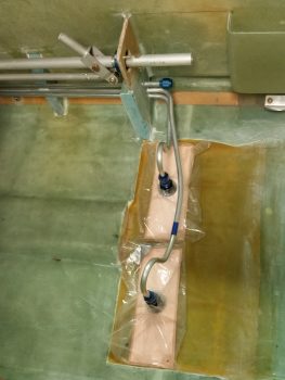
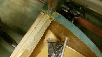
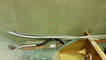
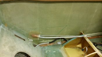
Here’s a shot of the left 1/2″ main tank fuel feed to the left sump tank, the 1/4″ left fuel sump vent line, and the oil heat return line which I added a couple of layers of heat shrink to reduce any radiating heat affect.

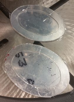
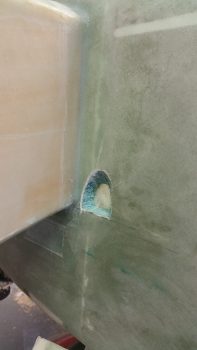
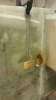
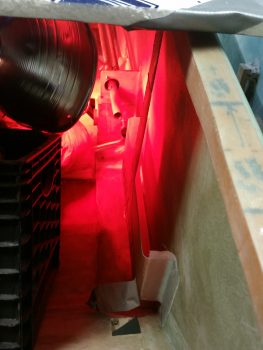
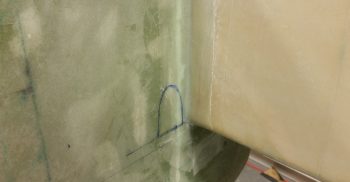
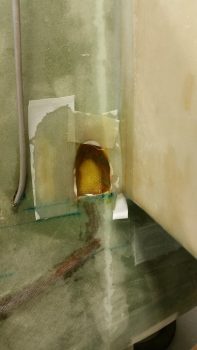
I sealed up the opening of the main fuel pickup tube at the main tank opening, then mixed up some more E-Z Poxy and made up some wet flox.  Then, using a syringe, I slowly injected flox on all sides of the fuel pick up line.  You can see the dark line where it filled in the spacing around the fuel feed tubing in the fuselage sidewall.  BTW, this area will get covered with a ply of Kevlar to protect that fuel line from any sharp dings or blows to the external wall of the aircraft (as will the glass-to-glass bonds in the fuel pickup area of the main tank).

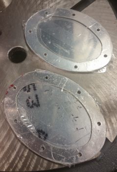
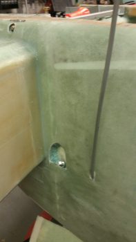
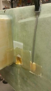
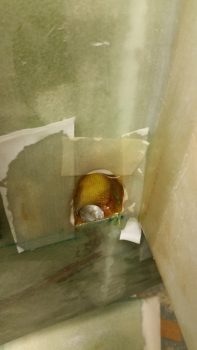
I then laid up 1 piece of Kevlar inside the alcove of the fuel pickup port, and then a ply of BID over the Kevlar, overlapping onto the fuselage (future fuel tank) sidewall.  In the second pic you can see the fuel pickup tube after I floxed it in place and glassed the area in the alcove above it.  I’m leaving the area around the fuel pickup tube raw flox for now since the exact elevation of the sidewall will need to be matched to the fuel pickup tube level.  Moreover, in both pics you may note that I’ve placed the top of the fuel pickup tube around 0.25″ below the cutout line.  This is to get the fuel pickup line close to what will be the level of the glass-to-glass floor of the main fuel tank.

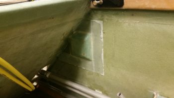
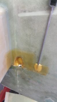
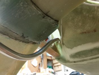
I then floxed around the inside entrance into the fuselage of the main left tank fuel feed and the sump fuel vent.  After floxing these lines in place, I then laid up 1 ply of BID over the entrance hole.

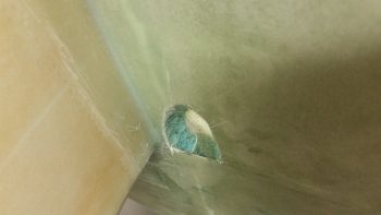
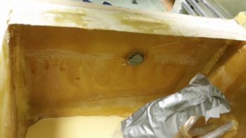
Here’s a closer shot.  I wanted to point out in the upper left of the pic that the external tank side fuel pickup port is just visible (note the yellowish area).

Finally, as the initial round of glassing on the left tank main fuel sump feed line & vent was complete, I then took a few minutes to pull the protective tape off the right low fuel sensor fitting that I floxed into the front wall of the right sump tank.  I cleaned up the flox a bit before calling this fitting install good.

Tomorrow will be a light build day, especially with all the issues I had with getting this blog post actually on the books!  I will be continuing working on the fuel sump and associated components until it’s pretty much completed.


Chapter 21 – Dam it!

Today I started by cleaning up both sump tank sides with a bunch of sanding to remove the peel ply boogers, dead glass and cut down the ridges at the glass intersections.  I also wanted to ensure the floors got a good sanding, with all the shiny spots removed in prep for the micro pour I’ll be doing on each side to cause any potential water in the tanks to flow outboard and forward to the fuel sump drain valves.

In addition, I looked around for some good material to make a dam to layup a ply of glass on the aft side of the left sump tank –starting out– then after the poured micro has cured I’ll use the in place dam for the right sump tank.

After not being able to find anything, I went to the usual aviation departments at the various stores.  Finally, at Michael’s (arts & crafts) I found some balsa wood that was thin, flexible but strong enough to keep its shape.  So I bought it, came home and resumed my build task after my multi-hour mini quest.

I then prepped the balsa wood by notching each aft corner so that it’d fit in place, then I taped up the front side with clear packing tape.  I then attached a piece of 3″ wide peel ply across the front by taping it at each end.

Here’s a not-so-great shot of the peel ply, which you can just make out the edge of at the top of the dam.

I then finished securing the dam with tape, and one small finish nail in the center.  I also placed a couple of sandbags pressing against the aft side of the dam to keep it nice and tight against the aft edges of the sump walls.  The middle rib dips forward just a bit which is fine because I actual wanted a bit of a dished shape for a better seat contour.  But really, it’s not much at all.   [Also note: the dam looks really askew in these pics, but it must be the camera angle because the sump sides are not different lengths as it looks to be portrayed in these pics].

I then mixed up a bunch of micro and stuffed it down in the corners along the intersection of the dam and the sump floor.  I then laid up 1 ply of BID onto the floor and dam front face (leaning forward) and also overlapping a bit onto the sidewalls.  I then let the layup alone to cure for a few hours before pouring in the micro floor contour.  Again, I am only laying up one side at a time to allow each layup to cure a bit before pouring in the micro, thus alleviating having to peel ply one side since I need to jack up the plane in a certain configuration for the floor to be “level” and cure to provide a correct flow.

I also cut to length and then taped up the bottom side of a 1.5″ wide Aircraft Spruce shipping board with clear packing tape before mounting it on the front top edge of the sump, overhanging aft over each sump tank an inch from the front sump wall.  After creating a micro fillet in the front top corner, I then laid up 2 plies of BID on the underside of the board overlapping onto the top aft of the front wall, and a little bit onto each sidewall.  This 1″ overhang will create a “top cap” that will give me more area to flox the sump top on before glassing the outside of it to the external sides of the sump.

I then went to dinner with a buddy of mine, and upon returning –at the 4 hour cure mark– I placed a 4×4 under the left wheel and one under the front wheel as well. I then whipped up some E-Z Poxy and made some wet, just soupy, micro.  I needed 2 batches to get the micro right and I had to adjust the elevation of both the front and left side of the aircraft to get the micro to spread out towards and up to the fuel drain valve.

I have to say pouring in the micro soup was a bit of a compromise.  I used as much micro as I could to lighten up the epoxy in the micro pour, but it took a fair amount.  I did’t originally shape the floor for water runoff aggressively at the beginning since I wanted A) the floor to have some depth to it to allow the installation of the fuel drain valves up deeper into the belly skin, and B) I needed to be careful around the outboard sides of the cutout floor foam because the embedded brake lines were very close to the outboard edges of the newly created fuel sump floor.

The consequence of all this is that I estimate I lost about a third of a gallon in volume tonight by pouring this micro in place, leaving me with about 1 gallon in this sump tank. Obviously, this leaves me with an estimated 2 gallons total in the sump tanks if this plays out the same on the right side.  I will of course have to confirm the actual capacity of each sump tank after I get them built.

Tomorrow will be a light build day, but I do plan on getting the right side dam layup done, and the subsequent micro floor contouring poured into place so I can hit the ground running on Monday.


Chapter 21 – Glassing sump walls

I started out today by pulling the peel ply and trimming up the edges of the layups on the wall sides that essentially make up the left sump tank, left & middle walls.

I then promptly glassed the right side of the middle wall, or sump rib, with E-Z Poxy to get it curing.

I then glassed the outside of the left sump wall using MGS, since this wall will not be in contact with fuel… hopefully!

When I did this layup, I also glassed a strip of BID on the bottom of the GIB right armrest storage pocket going to the sidewall.  Once cured, the GIB storage pocket will be glassed in once and for all.

I then marked up and did an initial cut on the right side wall to start the trial & error process of getting it to fit.

Here I’m about halfway through the process of fitting the right sump wall to the sump / fuselage floor.

And here’s when I finally got the shape along the bottom of the sump right wall dialed in.

Here’s an aft shot of the fuel sump’s right wall. Note that you can also see the fuel pulsation damper mocked up in these pics as well.

Once the shape of the right wall was good, I glassed it with a ply of Kevlar first, then a final ply of BID, just like I did with the inside layups of the other walls that make up the exterior perimeter of the sump tank.

One thing I was going to account for that slipped my mind until after I hurriedly glassed the interior side of the right sump wall, was that this wall needs to be a bit shorter due to it butting up against the back side of the right front sump wall extension.  I was so dialed into getting the difficult shape on the aft side of the wall completed, that I missed the front edge needing to be back 0.55″.  Since I had already configured the right side wall, I was going to merely trim the aft edge so it’s profile would match the other 2 walls.  But again, I jumped the gun in glassing the right sidewall so I didn’t get it done.

Fast forward many hours later, and I marked the left wall with 0.55″, aligned the two sides and then marked the aft/top of the right sump.  I trimmed the right sump wall immediately after this pic was taken.

As the interior layup of the right sump wall was curing, I decided to knock out making the oil heater pump base.  I started with the 1/4″ Finnish birch plywood plate I cut out the other day.  I rounded over the edges and then drilled 4 x 3/16″  holes.

I then marked the heads of the only 2 AN3-12A bolts I have onto the back of the mounting bracket and dug the wood out to keep the bolts from spinning.

The bolt heads are flush with the bottom, can’t spin, with still a good amount of wood to keep them in place.  Still, this plate will get about 5 plies of glass to hold it in place.

Here’s a side view showing the bolts in place.

Since I didn’t have any more AN bolts, and I wanted to get this mount finished, I stole the two 1-1/4″ bolts from the fuel pump and mounted them in the oil pump mounting base.  I then taped up the bottom of the vibration mounting pads, floxed the bolts in place and then set the oil pump in place over the floxed bolts.

And here’s a couple more shots of the oil pump on its mounting base.

I then used the oil pump attached to its mounting base to figure out where in the world I was going to mount this thing in the Hell Hole.  Since I just recently discovered that it is best to mount it horizontally (interesting, but that’s what it says!) I found a spot centerline of the aircraft, immediately forward of the gear bow and just aft of the GIB seat.

This all ties into the sump in that before I glass the front side of the fuel sump front wall, I need to know if I’m going to mount the oil heat line fittings into the LEFT sump front wall extension.

To figure out my oil heat oil lines, I needed to make some.  So I did.  I made the feed line that feeds the oil to the heat exchanger from the oil pump.  It all looked good on the top side . . .

. . . as you can see here . . .

But since I don’t have a 1/2″ tube bender, I resorted to a spring kit for bending the 1/2″ tubes.  The spring works well enough on simple bends, but it just can’t handle really tight turns without crimping or flattening the tubing — as you can see in this real tight turn to the right.

I’ll assess further, but right now I’m thinking at least the oil feed line will most likely need to be a braided cable to provide me the flexibility that I need.

With that, I then made up an oil return line.  Since it doesn’t need to make a hard right turn to get to the oil pump, I didn’t think this one would have as much of an issue as the oil feed line.  And it appeared not to.

One interesting point in the pic below: I played around with the spacing and tubing run for a bit before deciding on exactly where I wanted the Adel clamp to be located to hold the 2 oil lines (feed & return).  Well, I reached into my pocket to get my trusty Sharpie, but, uh, no Sharpie.  So, I picked up a small Phillips screwdriver and gave it a nice sharp rap to make a mark…. well, it was a bit harder than I thought and it made a nice dent in the wall. So, another wiggle and another rap, and in she went…. I guess this will be a RivNut hardpoint vs a Clickbond!

A shot of the oil return line from below.

For now I’ll just count the oil return line good, and then later when I finalize the firewall configuration I’ll cut the oil return line and terminate it with a fitting.

Tomorrow I’ll continue working on the fuel sump.  I’m hoping to have it done in the next few days.


Chapter 16/21 – Uphill slog . . .

This morning when I happily went down to check out my layup, I didn’t stay happy very long.  As I was ripping off the peel ply, which is admittedly one of the best ways to start out a morning, a couple of areas still seemed a bit soft and not fully cured.  This was not really what I was expecting since I had used fast hardener.  Ironically, I had just had a discussion within the preceding days on fast hardener, as I extolled its virtues.

There is of course a possibility that I jacked up the ratio, but I am usually pretty good at ensuring those are correct.  Regardless, I decided to cook it for a while and set my sights in at a good post cure temp: 140° F for 4 hours.  Over the next couple of hours I checked various spots and never had the IR thermometer go past the mid 150° area, and only in a couple spots.  And I was checking just about every area in each heat lamp’s path (more on this below).

Besides the heat lamps, in this pic below you can see that I glassed the aft side of the GIB armrest storage pocket with 2 plies of BID.

Here it is a bit later after it cured.  Note the yellow spot at the front side.

And below you can see the yellow spot again.  After establishing that my average temps on all the stuff I checked being in the heat area, including the sidewall and the storage pocket, were in the high 120s to high 130s, I ran out to grab a bite to eat and go to the store. When I checked the heat lamps a bit later I saw this discoloration.  I immediately checked the temp as I was pulling the lamp away, and it was 162.9°.  I also did a quarter test and could find no delamination.  Since a good portion of the yellow will get cut out when I open up the sidewalls for the baggage area, I’ll check the foam & glass again then.  But for right now, nothing seems odd except the color change.  Moreover, MGS 285 epoxy should have a multi-hour post cure over 170°.  I guess just that high of heat concentrated on that one spot over time caused the discoloration.

Moving on.  Note that the right front sump wall extension piece layup is complete!  The heat lamps did there job and the spots I was concerned about cured nicely . . . except one.

The area on the aft side of the foam at the bottom didn’t seem to be fully cured.  If this were slow hardener I wouldn’t have worried about it, but since the other areas were cured, this concerned me.  Now, it still looked like a solid layup, but the overhanging glass was just a bit too pliable for my liking.  I decided that in the 1 inch area that I would be laying up the BID tape for the outside of the right sump wall, that I would remove this glass.  Since I had laid up 2 plies over just the one on the sump wall extension, I broke through to foam in a couple spots.  No worries.  I’d rather have fresh foam for the next layup then putting good glass over some that is a bit suspect.  As for the rest of that layup, it’s in there and sticking, but I have so much other glass around it, I’m not concerned if its strength is a little less than normal.

In the right pic you can see the front side of the layup.

I wanted to show the access holes on the outboard side of this layup: the top hole is for the bundle of small wires that will traverse this bulkhead heading back to the aft areas of the plane.  The bottom hole is for the 2 big power wires to go through.

You can see that I also made the big power wire channel on the foam fuel line bracket as well.

So here’s a shot of all the layups I did last night, after I cleaned it all up. One good thing that happened is that weighing down the fuel lines worked.  The fuel lines are in the correct position and have no tendency to try to rotate upwards.

I then finalized my dimensions and shape for the fuel sump profile.  I took some scrap 3/4″ thick Divinycell foam and cut the pieces for the left & right sump walls.  I then micro’d the pieces together.

I then cut out the middle sump rib from 3/8″ Divinycell foam.  I loaded everything in the backseat for a quick mockup to see how it all looked & fit.

I then spent a good 25 minutes shaping the left fuel sump wall.

I figured out the fit on the middle fuel sump rib as well.  If you’re wondering why the bottom of the middle rib is cut, there is a technical term for that: it’s called being unfocused, not concentrating on the task at hand and having a major brain fart!  I noted on the left side wall that the base of it matches the base of the front wall.  I then inexplicably picked up the middle rib and had it cut and was putting it back in to check before I even realized the mistake I had made! Luckily, this is foam and composites, and it’s all easily fixed!

I started with the interior left wall and laid up the first ply, which is Kevlar.

I then laid up 1 ply of BID on the interior left wall (ply #2), and then –after reattaching the bottom strip– I laid up 1 ply of BID on the left side of the middle fuel sump rib.

I then trimmed the overhanging glass down.

And peel plied the layups.

Previously, I had laid up the forward side of the GIB armrest storage pocket with 2 plies of BID and a 1″ strip of BID down the front face of the foam fuel line bracket.  I then checked those to ensure that they were good to go.

Finally, since my garage is in the low 70’s I decided to put the freshly glassed sump wall pieces under heat.

Then I realized it was a bit too much heat and turned off one of the lamps and moved the sump wall pieces a bit farther away.

Tomorrow I’ll continue to work on the thigh support fuel sump and try to get this thing knocked out . . . hopefully a bit more error free!