Chapter 23 – Clear Prop!

So today was PICTURE DAY! Remember getting all dressed up (or your parents mandating that you get all snazzed up) for school picture day?  Well, that’s what I did for the shop.  I started off by spending well over 2 hours doing some much-needed spring cleaning on the shop.

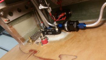
During my cleaning I took a few minutes to remove the ANL40 from the front side of the firewall in the hell hole and put it back upstairs and will install it later when I finish up the electrical components install in the nose.

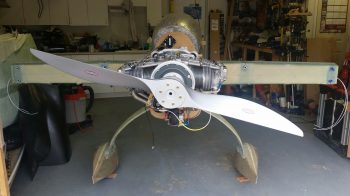
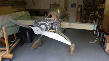
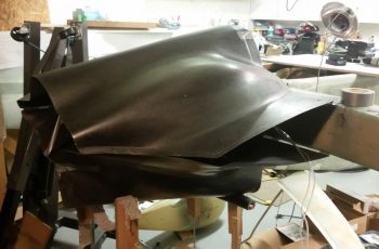
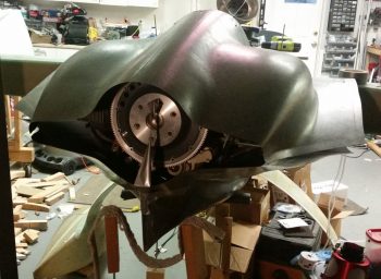
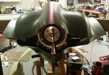
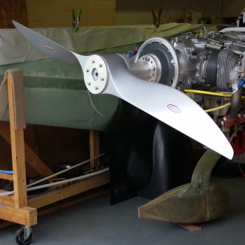
I then temp-mounted the propellor with the crush plate just for picture day. I was pleased with the how prop fit and looked mounted on the back end.

I took a slew of pics of course.  I ended up posting shots of the fuselage at different angles.  Believe me, I chucked a ton of pics out!  The main shot I was after was a straight shot from the aft end with the prop and wheel pants installed.

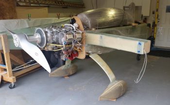
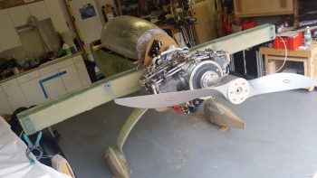
Here’s an angled aft view.

With these pics captured, my main goal is to weld up the angle-iron mounts that will allow the engine-on-mount to get mounted to the engine stand.

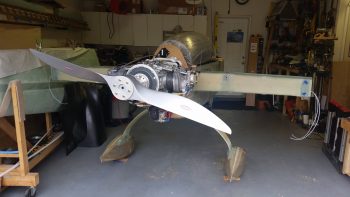
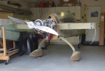
Although very close to the one above, I included this shot since it’s positioned a bit nose higher.

Another shot from a high angle.  In addition to the shots I took, my neighbor came over and set up all his photo shoot equipment and took a ton of pics with his high-end digital camera.   When I get those pics I’ll most likely post them here on my blog.

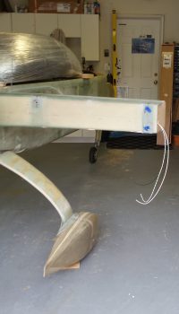
I’ll note that I’m very pleased with the how the wheel pants install turned out.

Here we have a shot of the installed right wheel pant with the canopy mocked up in place.

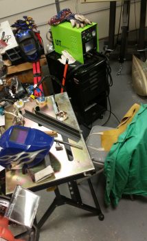
After the prop and fuselage pics were all taken, I then spent a good bit of time setting up my TIG welding kit for a good bit of welding that I need to do.  It’s been so long since I’ve welded with this box that at first I thought it was in-op.  Since this welder does stick welding as well, the ground connection on the front of the box is for stick welding, and the ground lead for TIG is actually labeled with a “+” sign…. which I finally figured out after spending a good amount of time tearing it apart and going through all the troubleshooting guides.

Tomorrow my focus will all be on welding, specifically the angle iron for the engine mount. In addition I’ll look to weld the oil heat standpipe tube to the 90° sump fitting and a tab on the aft right side of the roll over assembly to mount the canopy stay gas support.  Then my sights will quickly switch to getting the engine off the fuselage and onto the engine stand.

After I get all this welding done, and the engine on the engine stand, I’ll be transitioning into moving mode and to take a load of house stuff down to NC later this week.


Chapter 21/23 – Wired . . .

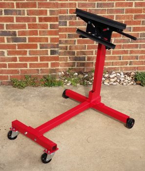
I started out today with kind of a fun little project: assembling the engine stand that I picked up at Harbor Freight with a 20% off coupon.  As I was assembling it, a note in the instructions caught my eye: “Not for use with Aircraft” . . . hmmmm?

I also set the lengths of angled steel on the top and bottom mounts to provide an idea of how those will mount to both the engine stand and the engine mount (this angled steel was one of the pieces that Marco cut for me on his ginormous metal band cutting saw… which cut through this stuff like butter!).

I then did about 2 hours worth of spring cleaning in the shop to get it a little squared away for all the upcoming activity.

Next, although I didn’t get a pic, I mounted the right wheel pant.  I noted some trimming I’ll have to do on the wheel opening, but it’s seriously on the order of about a 1/16th of an inch.  That will get it in line with the opening dimensions spelled out by Gary Hertzler.  In addition, I took some measurements on the right wheel pant that I had already taken on the left.  The conclusion was that the wheel pants match perfectly from the gear leg forward to the front pant tip.  However, from the TE of the gear leg to the back tip of the wheel pant the right one is about 3/16″ farther aft, or maybe I should say 3/16″ longer.  No big deal and it was more of a curiosity thing than anything… I can tweak it a bit when I finish the wheel pants.

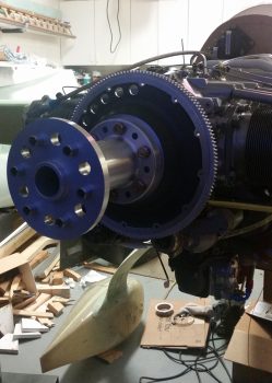
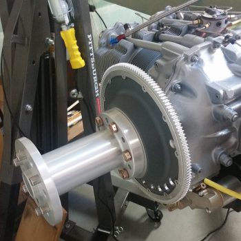
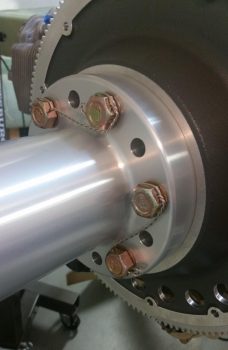
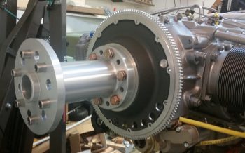
I then set my sights on mounting the 8″ prop extension to the flywheel and the engine prop flange.  It took about a half hour, a block of wood and a bunch of medium strength taps with a rubber mallet to get that sucker seated to within about 0.1″ of the flywheel. Then I very gently tightened all the bolts to get the prop extension to seat tightly against the flywheel.

Then, as per Sam’s (from Saber Manufacturing) directions, I torqued the 6 prop extension, prop flange and flywheel bolts to 50 ft-lbs each.

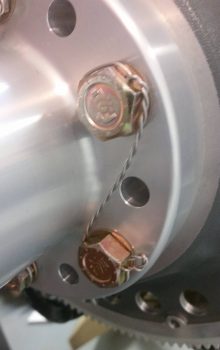
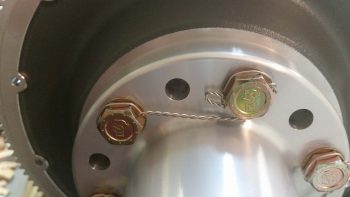
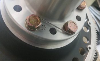
I then safety wired the bolts in pairs using 0.041″ stainless steel safety wire.

This is my first go at safety wiring, so if anybody out there sees anything disagreeable, please give me a shout.  I’m always open to constructive criticism.  Of course, I’ll have my EAA chapter bubbas look at the build as well.

Here’s the final shot of the installed prop extension.  Let me tell ya, the only time this thing is getting removed is when the alternator belt needs replaced! [Tomorrow I’ll test mount the prop and of course will take some pics… so I figured I would get the prop extension install out of the way today].

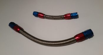
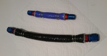
It was getting later in the evening, so I decided to relax and watch some TV while I played with my new toy: a ClampTite tool.  I removed and brought the fuel line and oil heat oil line with me upstairs.

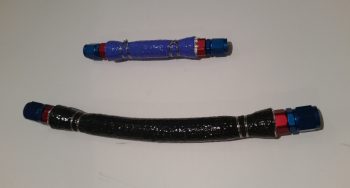
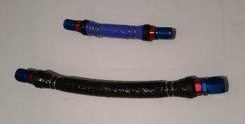
Then, using the Clamptite tool (another first for me), I fire sleeved the 2 hoses.  Note that I’m using blue fire sleeve for fuel lines and black fire sleeve for oil.

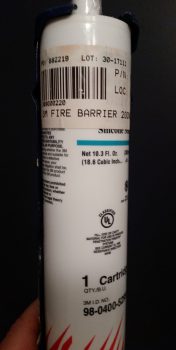
As I’ve seen on Joe Caraggio’s site and others, there seems to be a requirement out there (or at least a good idea) to seal up the ends of the fire sleeve so the wool-type lining doesn’t soak up any stray oil, fuel, or what have you.  I had some of the expensive gray 3M fire barrier on hand so I decided to seal up the ends with that.

Here I’ve applied the 3M Fire Barrier to the ends of each fire sleeved hose….

However, I’m not a big fan of how the gritty, blotchy gray Hi-Temp RTV ends looked, so I cut a narrow piece of heat shrink and covered the RTV’d ends up…ahh, much better!

My final build act of the evening was to simply reinstall the hoses back onto the engine.  I definitely think the fire sleeving will work and I’m glad I went this route.

Tomorrow is picture day and my next door neighbor will be using his Uber awesome digital camera to get some nice aft end pics of my Long-EZ build.  Once that happens, my next goal will be to get the engine off the fuselage and onto the engine stand.  I’ll then drop all my engine focused shenanigans and will start on finishing up the nose and getting the canopy built.


Chapter 21/22/23 – Schooled . . .

Today was a day of lessons for the ‘ol Airdog here.  First off, my buddy Dave B. asked me a question on this website regarding the use of an ANL type fuse link for the SD-8 backup alternator, and if I did use one was it located aft or in the nose?  Wow, ok… probably a question I should have asked myself and a big oversight on my part.

As I see it (after Dave’s prompting) the logic flows like this: I just moved the ANL40 fuse link on the B-Lead aft because the antagonist in my view was the main 40A alternator.  I again based this off of Bob’s statement that the fuse should be closest to the offending power source.  Ok, now the SD-8 backup alternator is in the back as well, but its 30A fuse –as spelled out specifically in the Z-13/8 system architecture– must be located within 6″ of the master contactor (in the nose).  But why?  The key I discovered is identifying the potential antagonistic power source, which I had done incorrectly.

I posted this question on the AeroElectric Connection forum and almost immediately got a response: the alternators are not the main point of concern since if the wire leads from them are rated at the max current they can produce, then the wire will be safe.  However, the battery is a source of potentially hundreds of errant amps hitting the wire if it decides to go a little haywire.

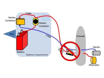
Thus, I had picked the wrong villain, and as Sun Tsu says, “Know your enemy.”   I did not. This of course meant that my action to move the ANL40 fuse link aft was all for naught, and moreover, incorrect.  Lesson learned.  So, my latest diagram should be depicted as such:

And my new configuration for the ANL40 is nothing more than my previous CORRECT depiction, shown here.   Ahh, the circle of life…. ha!  I haven’t yet moved the ANL40 fuse link, but I will be leaving the mounting pad on the face of the firewall in the hell hole until I know for certain that nothing else needs to get mounted in there.

In a subsequent discussion Dave and I discussed alternators going haywire, and as a point of note I’ll state that alternators such as the ones B&C sells have built-in OverVoltage protection to guard against runaway alternator current causing damage.

Moving on.

I had a lengthy discussion this afternoon with Mike Beasley, who many of you may know from his awesome website.  (Admittedly, there’s not a lot of verbiage on his site, but for the fellow Long-EZ builder the pictures on his website are a treasure trove of information).

Lesson #2 of the day for me was Mike providing me with the finer points of how he constructed his canopy.  We spoke a bit on a few other topics such as throttle and mixture cables, but the near 2-hour long conversation focused primarily on the canopy and nose build.  I am very thankful for the time that fellow Canardians take to collaborate on such tasks as this, and it really does make the build so much more manageable (and enjoyable).

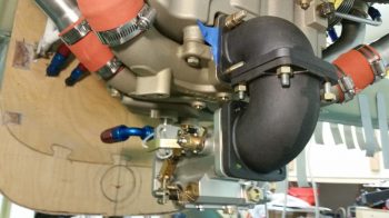
While I discussed the canopy and nose build with Mike, the FedEx guy delivered my last (hopefully) round of fittings that I ordered from Summit Racing.  Again, my first choice for connecting the hose coming down from the fuel distribution spider atop the engine to the -4 AN 90° fitting on top of the fuel injection servo was the 150° hose end fitting.  And as I mentioned before, my backup was a 90° hose end fitting if the 150° hose end didn’t work out.

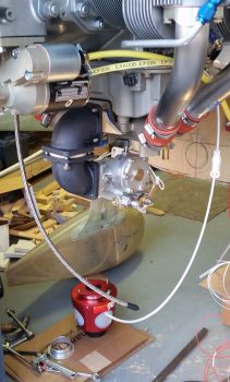
Quite nicely, however, the 150° hose end fitting worked like a champ!

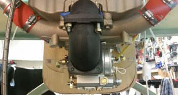
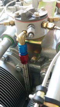
For this fuel line, I also employed and test fitted an Adel clamp secured by the front left corner bolt where the induction air intake elbows mate together.  I think this Adel clamp position will work nicely to secure the -4 hose going to the fuel distribution spider from the top-mounted fitting on the fuel injection servo.

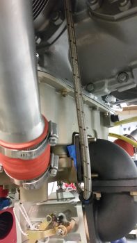
Here’s a bit closer view of the -4 fuel line feed to the fuel distribution spider from the fuel injection servo.

I then took a while to figure out and dial in the position and angle of my oil sump oil heat feed line that exits out of the bottom of the oil sump via a 90° steel fitting (that I calculated a 4.4″ tall standpipe will get welded to) to a firewall pass-thru fitting.  I had some angled hose end fittings on hand, but decided that to keep a nice constant curve around the RAM air box that I’d use straight hose end fittings.

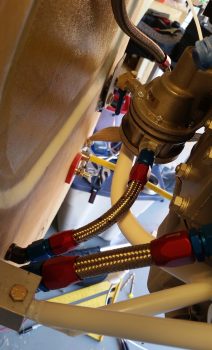
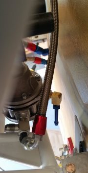
I then spent a couple of hours assessing and dialing-in the flow and Adel clamp attach point for the final piece of hosing to complete the fuel line from the fuel intakes in the main strake-located fuel tanks to the cylinder fuel injector nozzles: the -6 hose from the fuel pump to the fuel injection servo.

At the fuel pump side I actually entertained the idea of cutting part of the flat flange insert at the corner of the engine mount in order to have the fuel pump out hose end fitting face outboard of the engine mount tube.  But, laying below the engine looking straight up at it, I realized that more of the hose end fitting was showing on the inboard side than the outboard side, meaning that I could get a more down angle of the hose end fitting by leaving it inboard.  So, no drilling or cutting of the engine mount flange took place.

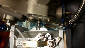
On the fuel injection servo side, I had planned on actually running the hose aft and looping it in from the aft side to arrive at the fuel injection inlet fitting at a 0-45° angle. But then after looking at and assessing the travel of the mixture lever on the fuel injection servo, I decided to simply bring the fuel line down from the top from a slight forward-to-aft angle.

So here it is: the final fuel line piece for this entire aircraft.  Yes, of course the fuel VENT lines will still need to be run, but this does it for the actual fuel lines.

Tomorrow I’ll prep for the removal of the engine since I have the lion’s share of data that I need from having the engine mounted.  Moreover, I’ll most likely clean up the shop and take some pics of engine mounted on the fuselage before removing it.


Chapter 23 – RAM’in Air

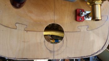
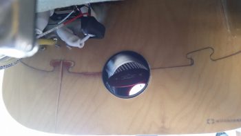
Today, after a fair amount more research, I got down to the shop and pulled the trigger on drilling the 3-1/8″ hole in my firewall for the nose flange of the RAM air canister to fit into. As you can see by the original marks on the firewall, my new location is significantly higher on the firewall than where I had planned to place it originally.

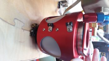
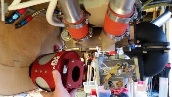
I then test-fitted the RAM air canister and as I’ve mentioned many previous times, it does just fit . . . barely.  But it fits!!

Here we have the RAM air canister peeking through the firewall from the Hell Hole side.

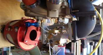
And even though the RAM air canister is tilted down a bit on the aft end –since I’m not holding it in place– you can see the position of the aft air exit hole and how a piece of tubing from the RAM air box to the fuel injection servo will be clear of any entanglements from above such as the oil drain valve and the oil heat feed fitting.

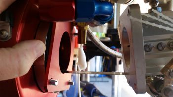
Since I moved the fuel injection servo forward to position the top 90° outlet fitting into a “V” groove on the bottom side of the Superior cold air induction plenum for clearance, that reduced the distance between the aft face of the RAM air canister to the front face of the fuel injection servo from 5.5″ down to only 3.7″.  Still enough to allow flexing between the firewall-mounted RAM air canister and the engine-mounted fuel injection servo.

Also note in the pic below that the tubing in-between the 2 units will need to curve upward at the aft end about 1/4″ due to the position and angle of the fuel injection servo.  I don’t see this as being an issue since I will be using flexible SCEET tubing.

Here’s a wider angle shot showing a close view of how the units will look in their final installed configuration.

I then spent a good 30 minutes dialing in the location of the firewall mounted MAP sensor/ fuel pressure sensor/oil pressure sensor manifold block.  I think I’ve pretty much got it’s mounting spot located, but need to check just a couple more things.

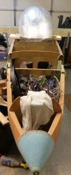
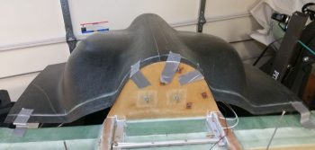
I then started reviewing my canopy install and build plans.  I set the 4130 steel rollover assembly in place as well as the headrest to prep for putting the canopy in place and assessing clearances [A couple notes: A) the headrest will get repainted since I had that issue with 2 different paint styles coming from cans with the same label, and B) the white thing on top is my GPS Antenna “radome”… in case you were wondering.)

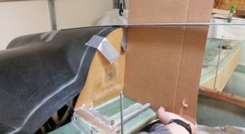
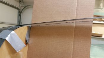
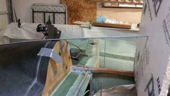
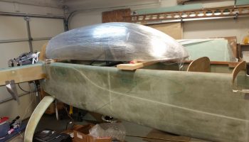
I then grabbed my canopy out of the back room and set in place on two 2x boards. Although the angle is still a tad bit shallower than I’d prefer on the front of the canopy, I still like this canopy much better than my first one.

Here’s a canopy shot from the front that I was curious to see.

With that, tomorrow I’ll be finalizing my engine-related tasks in prep for pulling the engine off the fuselage and mounting it to its engine stand, and concurrently I’ll be prepping for the nose and canopy install/build.


Chapter 16/22 – B-Lead fuse link install

Since I know I’m off my engine removal schedule by a day or two, while I await the fittings to finalize the fuel/oil lines I worked on something that I want to get done as a self-perscribed prerequisite to drilling the 3-1/8″ hole in the firewall for the RAM air canister: mounting the ANL40 fuse link and base.

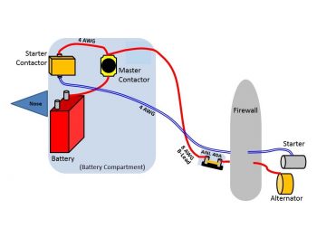
If you recall, after much consideration I modified my starter and charging circuit design by separating out the B-Lead into its own dedicated cable and by moving all the associated components to the nose-located battery compartment as such.
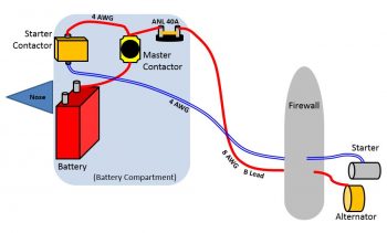
However, even though this configuration has been implemented successfully (reportedly), I was never too keen on the ANL40 being so far removed from the line it was protecting.  I chalked it up to 2 things, made a mental note to assess it, and then pressed on.  Those 2 things were that A) Again, its working in a real-world install, and B) 10 feet is not a huge distance to electrons that travel the speed of light.

However, as I pointed out a couple of days ago, Bob Nuckolls reminded me of a core principal that I was not following in regards to my ANL40 Fuse Link location when he stated, “Recall that circuit protection is for WIRES . . . and that the protective device is installed as close as practical to the SOURCE of energy that puts the wire at risk.

Again, as a result, my ANL-40 fuse link is going back on the firewall, on the hell hole side. However, instead of employing a 1/8″ thick x 1/2″ wide copper strip, I went with my optional configuration and am using 8 AWG cable to connect the forward (hell hole) stud of the Blue Sea terminal to one side of the ANL40 with the GRT EIS HALL EFFECT SENSOR placed in-between, then run the B-lead from the ANL40 forward to the battery contactor. Therefore, my new starting & charging circuit configuration now looks like this:
My 2 goals for the day were to install both the ANL40 base, fuse link, etc. and the GRT EIS Hall Effect sensor.

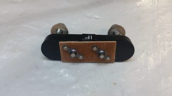
I started by ginning up a phenolic nutplate assembly with the same #10 screw pattern as the ANL40 base.  Since the fuse link sits in the middle of the 2 posts on the base, the only screws that can be used are countersunk screws.  Since I’m mounting the unit on the front face of the firewall I clearly can’t put nutplates on the aft firewall face, so I had to go with a in-Hell Hole surface mount solution.
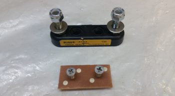
Here’s the aft side of the ANL40 nutplate assembly.
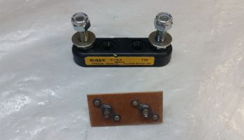
And a couple shots of the nutplate assembly installed on the ANL40 mounting base.
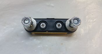
To embed the nutplate assembly onto the forward firewall surface in the Hell Hole, I made a mounting pad for the ANL40 mounting base from 3/8″ PVC foam.
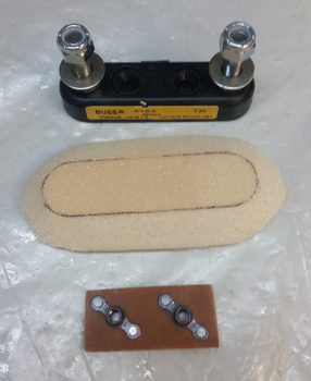
I then carefully carved out a notch for the nutplate assembly in the foam mounting pad.
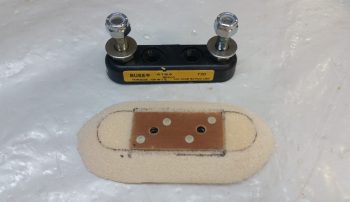
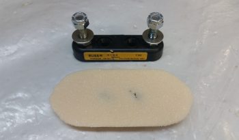
Here’s a bottom shot of the foam mounting pad with the nutplate assembly installed.
I then used 3 plies of glass (BID/UNI/BID), prepregged, and glassed the ANL40 foam mounting pad with the nutplate assembly flocro’d into place (with all the typical pre-work: micro-ing foam, etc.).  Again, the mounting pad was glassed onto the forward side of the firewall in the hell hole.

Off topic a bit here, but as the layup above cured, I decided to finish off the elevator control rod by drilling a #10 hole and mounting an AN3-7A bolt into the hole (IRRC this is a Ken Miller mod….).  The bolt will be in addition to the clevis pin that secures the forward side of the elevator control rod to the aft side.
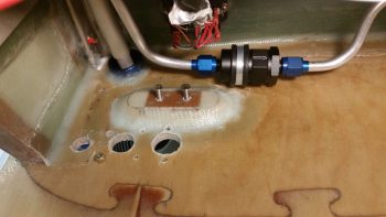
A few hours later I cleaned up the cured layup (yes, I used fast hardener) and test installed the 2 ANL40 base mounting screws.  I also trimmed the glass overhanging the existing firewall electrical package component holes and redrilled the upper holes for the mounting screws.
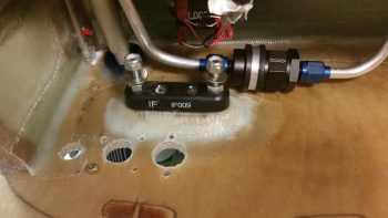
I then mounted the ANL40 base into place with the 2 countersunk screws.
And remounted all the firewall electrical package components (again, except for the ANL40, these are all temp mounts until the Fiberfrax and 6061 aluminum firewall cover are in place).  I uploaded both pics of this since they show a bit different viewing angles.
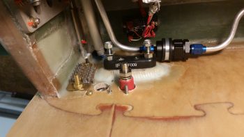
Being able to get a feel for the space between the Blue Sea B-Lead connector (it’s red) and the ANL40 base, I then got to work finalizing the GRT EIS Hall Effect sensor configuration.  I trimmed the long 8 AWG wire and terminated the Blue Sea connector end with a 3/8″ terminal.  I also labeled & trimmed the ground wire, then terminated it with a Fast-ON PIDG terminal.
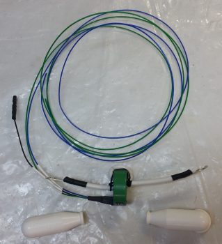
I slipped on the white rubber boots, and Voila! Ready for install.
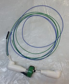
Since I’ve had the actual ANL40 fuse link for a number of years, there was a bit of tarnish on the metal blade connectors so I used a Scotchbrite pad and some white vinegar to clean them up a bit.
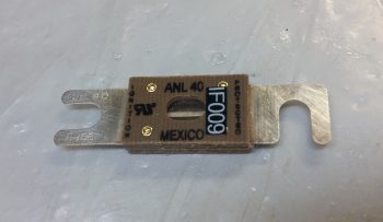
I then installed the ANL40 fuse link into its base, on top of the glassed-in foam mounting pad (with the embedded nutplate assembly) and then got busy connecting all the cables to their appropriate mounting lugs.

I also co-ran the red 14 AWG SD-8 backup Alternator power feed wire through the GRT EIS Hall Affect sensor a couple of passes (both the primary alternator B-Lead and the SD-8 backup power feed get passed through the Hall Effect sensor twice to place the readout scale on a 0-50 Amp scale vs a 0-100 Amp scale… the latter which I don’t need since my primary alternator only puts out 40 Amps max).

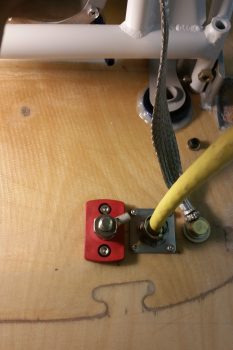
The route of the electrons is this: Alternator current runs via B-Lead to the firewall side of the Blue Sea pass-thru connector (red fitting), then on the inside of the Blue Sea pass-thru a cable runs to the right post (in pic below) of the ANL40 fuse link VIA 2 passes through the Hall Effect sensor donut.  Then, from the ANL40 left post (again, as depicted in pic below) an 8 AWG B-Lead cable carries the current up to the nose, connecting to the Master Battery Contactor (as depicted in my updated diagram way up there ↑).
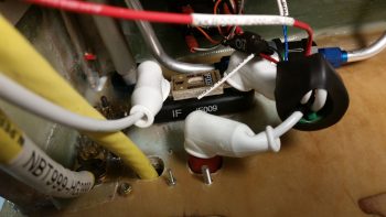
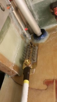
Here’s a closer up shot of the installed ANL40 Fuse Link.
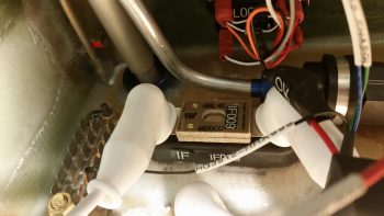
In addition, you can also note that I used a decent sized piece of heat shrink to seal and cinch up all the wiring going through and wrapped around the Hall Effect sensor donut.  It may seem like the Hall Effect sensor is left to sway to-and-fro in the wind, but with the robust 8 AWG cable securing it in place, and the amount of force I had to apply to get both terminal ends in place (not excessive, but it’s tight) …. that puppy ain’t budging!
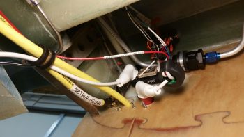
Another angled shot of the ANL40 fuse link for the alternator’s B-Lead feed and the GRT EIS Hall Effect sensor . . . plus note the additional “big” wire runs that are deemed big enough to hang out and traverse the fuselage with the big yellow cables.
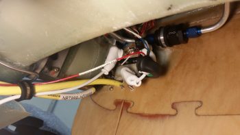
And a final parting shot for the evening.
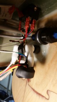
Tomorrow I’ll continue to work my tail off to get all the engine & firewall components/hoses installed, ID’d, configured, and/or mounted AND data collected before I pull the engine off the fuselage.  [I will note that I baked 2 batches of pinkish colored desiccant to refresh the engine dehydrator].

 

Chapter 23 – Cowl me crazy!

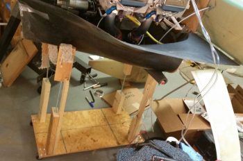
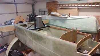
I actually spent quite a few hours today building a lower cowling dolly that you’ll see in a number of the pics below.  I saw one of these in Walter’s hangar as we were helping remove the wings off of his Long-EZ and thought it was a good idea.  Well, although I got the dimensions from Marco, they didn’t translate over for whatever reason to my cowling and build dimensions (possibly since my fuselage isn’t loaded all the way down?).  I still used it to a degree, but I will have to mod it much further for it to really be helpful.

My goal today was to mock up the lower cowling in its close to final position (as best possible) to check the clearance between it and the engine air induction system… specifically the fuel injection servo.  To better ascertain the position of the lower cowling, I went ahead and set the top cowling in place, which I was going to do in short order anyway.

I then used duck tape to help wrangle the 2 cowling halves into some semblance of order. I’m definitely happy with the fit of the cowlings, and although Mike Melvill had an IO-360 inside of them, trust me, they are still a close fit to an IO-320 sized engine.

I taped the cowling at the top cowling-firewall interface, and was glad to confirm I have a good firewall fit, with the shape of it matching the cowling shape.

Since I had the top cowling close to its final position (I double-checked the plans, my notes, other builders’, etc. to ensure I had it close to where it needed to be…) I then made some templates to use for the cowling angle interface with the canopy and D-deck/ turtledeck assembly.

Here’s another view of my canopy-top cowling interface angle template.  Clearly I will most likely need to throw a curve into the mix as I mount the canopy, but it gives me a good starting point.

I also drew hash lines on the longerons and marked the extended angle of the top cowling contour about 18″ forward of the firewall.

Here’s my version of the lower cowling dolly.  Mine needed to be much wider front to back and much taller than the one that Walter built for his airplane.

As you can see, I removed the top cowling to better check the clearance between the bottom cowling floor and the fuel injection servo.

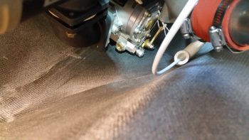
Here’s the best shot I could get of the fuel injection servo position inside the lower cowling. It may be hard to tell, but in this configuration there is NO clearance and the cowling is actually just touching the fuel injection servo. In fact, the very bottom nub sticking out to the right on the servo is the main fuel feed line attach fitting… clearly no room even to connect the fuel feed hose!

Very frustrated and perplexed on my no-clearance issue with my lower cowling, I took a break and grabbed something to eat.  After about an hour, with the worst case scenario of having to extend a trough under the lower cowling in my mind, I went back down to the shop to assess the clearance issue.

As I was literally sitting under the engine just looking at the layout, I came up with a very viable solution.

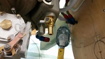
You see, my paradigm was that the main fuel line was coming in from the right side, and the hose coming in from the fuel distribution spider on the top of the engine was from the left.  No need to change any of that, but I did need to rethink the one thing that was really causing my clearance issues: the -4 AN 90° fitting on the top of the fuel injection servo. I had it pointed to the left as I lamented the lack of clearance between it and the bottom of the oil sump . . .

But if I moved the servo about 1/2″ forward (which I could do since I had spacers installed in between the elbows), not only did it push it forward to where the cowling was lower, but if I faced the top fitting to the RIGHT then it put the fitting right into a V-shaped channel on the bottom of the Superior cold air induction oil sump.  This allowed clearance to get the hose end fitting onto the servo outlet fitting!  Yes, I would have to spend another $20+ on yet another hose end fitting, but by doing this configuration change it gave me 2 options: A) Run the fuel distro spider hose above the fuel injection servo and in front of the air duct elbows with a 150° U-turn hose end fitting, or B) Run the fuel distro spider hose aft of the air duct elbows with a 90° hose end fitting (I’ll admit that to acquire the best solution here I bought both fittings…).

I’ll have to assess this when I get the fittings in and test these fuel line runs.  This leaves the right side main fuel feed line unaffected and it will still attach to the fuel injection servo on the right side (low).

The resulting change in my configuration will require only about a 3/16″ phenolic spacer between the lower 85° elbow and the fuel injection servo.  I will also have to replace the threaded studs on the cold air induction plenum for connecting the upper elbow to the plenum (at a minimum the lower studs, since it is virtually impossible to get a nut with so many washers on them with the current configuration).

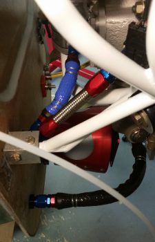
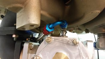
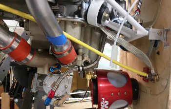
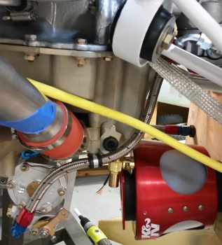
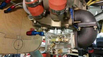
In figuring out the final install point and configuration of the RAM air canister (not pictured here) I needed to install the 1/2″ NPT elbow on the bottom of the oil sump to assess how to route the hose from the sump to the firewall…. around the RAM air canister.  I tested a 90° hose end elbow (blue & red) but think a straight hose end may work as well.  However, since the oil heat feed line from the sump looks like it will enter the firewall on the lower left side, this will require the associated hell hole oil line to crossover from the right side oil pump fitting over to the lower forward left side of the firewall (again, crossover in the hell hole).  Not a big deal, but I will have to avoid and go above the RAM air intake expansion chamber ( . . . never-ending ripple affects!).

The bottom line is that it looks like all the components should fit, but the clearances from one component to the next are all AMAZINGLY CLOSE (but, I will note not too close to allow vibration to cause issues).

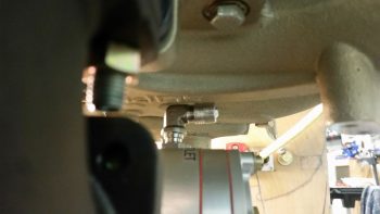
Here we have the oil drain valve with the oil heat feed 90° fitting just behind it (pic from right side of engine).

I’m fairly confident that this configuration will give me just enough of the clearance I need below the fuel injection servo and allow for all the critical air induction and underside oil sump fittings to play nicely with each other.

Of course I will have to also rotate both the fuel injection servo’s throttle and mixture levers to avoid hitting the lower cowling (I planned out the mods on those a few days ago), but again, I don’t foresee any issues with those as well.

I think with these sideline tasks taking a bit more time than I expected, my timeline for getting the engine back off the firewall and onto its stand will have to slip a day or two. Tomorrow I should be close to finishing up the firewall configuration tasks and pulling any more data I need to from the engine being mounted.


Chapter 16/23 – Air, MAPs & Elevator

I started off today by making a decision on my electrical system, one that had been nagging me a bit in the back of my mind.  The impetus for me making this decision today was a response by Bob Nuckolls on the Aeroelectric Connection forum that brought it all home for me.  In a discussion on something else related to protecting wires with fuses and circuit breakers, Bob noted: “Recall that circuit protection is for WIRES . . . and that the protective device is installed as close as practical to the SOURCE of energy that puts the wire at risk.

Thus, my ANL-40 fuse link is going back on the firewall, on the hell hole side.  I’ll most likely use a piece of 1/8″ thick x 1/2″ wide copper to connect the forward (hell hole) stud of the Blue Sea terminal to one side of the ANL-40, then run the B-lead from the ANL-40 forward to the battery contactor (however, I’m leaving the option open to use 8 AWG cable and use this connection as the location for the GRT EIS Hall Effect sensor).  This configuration will add a hair more weight aft, but puts better protection on the source of the B-Lead and cleans up my busy nose battery compartment a bit.

I didn’t mention conversations I had yesterday with both Rod Bower (RAM air unit) and Precision Airmotive (Silver Hawk fuel injection) as Marco and I were convoying in our separate trucks to his hangar.  I asked the Silver Hawk guys if I could attempt to thread the -4 AN fitting on the top of the fuel injection servo as far as it would go into the unit in order to attain as much clearance as possible with the bottom of the cold air induction plenum situated just above the fitting.  They said this would be no problem and that I wouldn’t damage anything internally/inside the fuel injection servo.

I queried Rod on some specifics about moving my RAM air box forward and mounting it directly to the aft side of the firewall, but he couldn’t picture it mentally and I ended up sending him the pic below much later after I arrived back home.

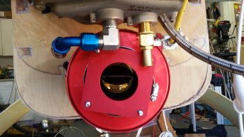
Rod got back to me today and we discussed mounting his RAM air unit with the nose of it sticking into the firewall, with about a 5.5″ gap between it and the front face of the fuel injection servo intake plate.  The requirement for this gap between the RAM air canister –which would normally mount to the front of the fuel injection servo– is twofold: 1) The RAM air canister is too wide at the aft side of it (note that it’s shaped somewhat like an Apollo capsule) and would interfere with the bottom cowling.  2) There would be no clearance for neither the oil drain valve (brass valve in pic below) nor the forward-placed sniffle valve.

To allow for enough clearance with the aft end of the RAM air canister with both the oil sump above it and the lower cowling below, I determined that it must be mounted in the clear space just forward of the oil sump.  This spot will allow the RAM air canister to be mounted an inch or so higher and still clear all the top side oil sump/cold air induction plenum and the lower cowling below . . . barely! 

[In the pic below you can see the location of my initial planned hole for a 3″ bracket (shown bottom left corner), then a piece of 3″ SCEET tubing, then the RAM air canister mounted to front face of the fuel injection servo.  Clearly, the reality of limited space and conflicting requirements for use of that space significantly changed the configuration of my air induction system.  Currently the plan is to install the nose of the RAM air canister approximately 1″ higher than the circle depicted on the firewall below].
After some discussion Rod was able to see what I was talking about and signed off on the plan.  In response to my question, he stated that he saw no ill affects in his assessment of my running a 2.5″ piece of SCEET tubing from the aft side of the RAM air canister to the front intake of the fuel injection servo (note smaller diameter than that previously planned 3″ SCEET tubing preceding the RAM air canister).
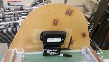
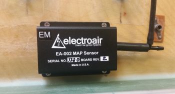
After getting Rod’s sign-off on the new air induction configuration, I then got busy mounting the Electroair MAP sensor unit on the front face of the firewall in what will be the GIB headrest/D-Deck component housing.

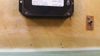
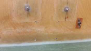
I marked the holes and here you can see the top 2 holes are drilled.

I then had to make some minor adjustments for hole alignment as I drilled the remaining 2 holes.

I then test fitted the MAP sensor, but will hold off on the actual screw install since I don’t have good access with the engine installed to the aft side of the firewall (the screws will get floxed in from the aft side of the firewall to the front side to create 4 screw posts… analogous to click bonds).

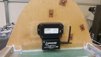
And another shot of the final placement of the GRT and Electroair MAP sensor units.

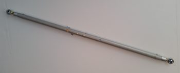
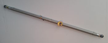
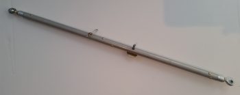
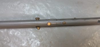
I then got busy assembling the new 5/8″ elevator control rod that would replace the old one that I so haphazardly decided to drill an extra hole into.  I used some larger rivets that Chris Seats gave me and got busy drilling and mashing rivets!  Here’s the assembled product.

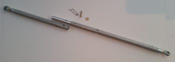
Here you can see the internal rod that Marco lathed down the diameter of and cut to length.  We of course cut the 2 main tubing pieces to length as well.  Since I have so much real estate on the top end of the quick disconnect internal solid rod, I’m going to drill an extra #10 hole and actually install an AN3 bolt and nut in addition to the clevis pin.

Here’s a shot with the Atkinson pitch trim actuator bolt slid into the bolt hole that I drilled on this new 5/8″ elevator control rod.  Again, the internal solid rod that makes up the quick disconnect also extends down beyond the pitch trim actuator bolt hole so the hole is much more robust than on the previous elevator control rod.

And here’s a view of the other side of the pitch trim actuator connecting bolt.

Tomorrow I’ll continue to finish up engine-related tasks and will specifically focus on the final placement and configuration of the air induction components.

Chapter 16/23 – Lathing about

Marco, his wife Gina, and I all attended a very nice memorial service for a fellow Canardian, Walter Grantz, who sadly went West a few weeks ago.  Marco spoke at the memorial and told some wonderful stories of our friend Walter, who will be missed greatly.

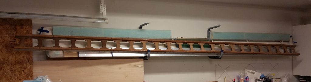
The next day Marco and I had the privilege of helping Walter’s son, Art, and grandson, Christian, remove the wings off of Walter’s Long-EZ to ready it for transport down to NC State University, since his beloved Long-EZ is being donated as a static display for the university’s Engineering Department.  During the time we spent at Walter’s hangar, Art was kind enough to give me Walter’s long level board that Walter had used to build his Long-EZ back in the 1980’s.  It will truly be an honor for me to use it when I build the strakes, and here it is hanging on my shop wall.

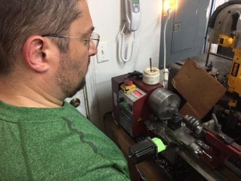
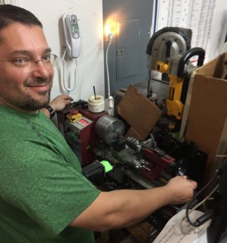
Later that evening, Marco was gracious enough to do a bit of machining for my build and lathed the midpoint quick disconnect insert bar on what will be my new elevator control tube [If you remember, I drilled an “extra” hole in my other one and didn’t want to fly with it with an unnecessary hole that only would serve to weaken a critical flight control component.  Moreover, Chris Seats gave me some info and components to help me upgrade to a 5/8″ diameter tube vs the 1/2″ stock… not that the stock version is deficient, it just happened to be easier for me to build a 5/8″ version].
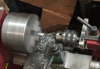
Marco lathed the midpoint quick disconnect insert bar from a 5/8″ rod of 2024 aluminum down to just a bit of over a half inch in diameter.  We also cut it to length to allow for not only the quick disconnect clevis pin(s) & rivets to be mounted, but also long enough that the new (and correct) pitch trim actuator connecting hole will now be drilled through both the control tube and the lower side of the quick disconnect insert bar… clearly a much stronger mounting hole since it will be solid metal for the entire width of the hole. (Sorry… I don’t currently have any pics of these parts, but I should in the next day or so…)
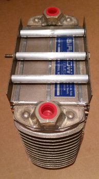
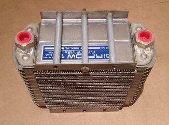
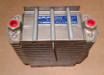
After we got the more important elevator control tube out of the way (we also cut the new 5/8″ control tube pieces to length), we then cut two 1 foot lengths of 6061 3/8″ rods into 3 lengths that fit in-between the mounting tabs of my oil cooler.

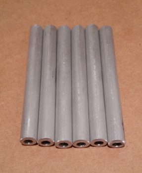
Marco then used the lathe to drill out a 3/16″ hole down the center of each one of the oil cooler mounting spacers.

Here are the 6 oil cooler mounting spacers with holes drilled to accept AN3 sized mounting bolts.

Here are the top 3 oil cooler mounting spacers set in place, with the middle one mocked up with an AN3-41A mounting bolt.

And here are another couple shots with the top 3 oil cooler mounting spacers in place with a test fit of an AN3-41A mounting bolt.

Of course Marco did an outstanding job on all the parts he machined/lathed for me (Thanks Brother!).

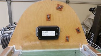
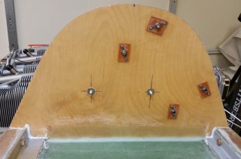
I wanted to get some glass curing overnight after I got home from Marco’s, so I spent a good half hour figuring out the best spacing and mounting for the 2 MAP sensor boxes… one for the GRT EIS and the other for the Electroair EI.

Originally I had planned on mounting them both vertically, but when I assessed the internal configuration and best spacing within the GIB headrest/D-Deck area, I decided to place them both mounted horizontally, as the GRT MAP sensor is below (with the Clickbonds 5 min glued in place).  The Electroair EI MAP sensor box will get mounted directly below the GRT MAP sensor box.

After letting the 5-min glue cure about 10 minutes, I then removed the GRT MAP sensor box.  I cleaned up the excess 5 min glue and sanded around each of the Clickbonds.

I then laid up 2-plies of BID over each Clickbond, peel plied them both, and then left them alone to cure.

I should note that Marco also used his big metal cutting bandsaw to cut up a 36″ piece of angle iron that I will use to weld up a mount that will allow the engine mount to be connected to the engine stand.  Over the next few days I’ll be getting that ready to go as well, after I get just a bit more data from having the engine mounted.


Chapter 23 – Hosed!

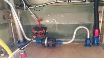
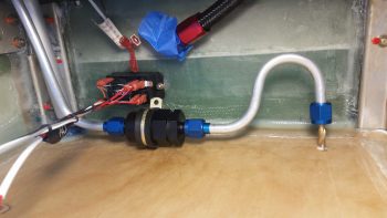
I started off this morning inventorying a much-needed order from ACS that I just received. Included in the order was -20 sized Adel clamp for the fuel filter, that I immediately pressed into service.  I cleaned the fuel lines fore and aft of the fuel filter then mounted them “permanently” (albeit servicing will occur…yes) to the filter, as well as permanently mounted the origin of the incoming line of the fuel filter (on left in pic below) at the FT-60 Red Cube fuel flow transducer.

I also received the 45° -6 AN bulkhead pass-thru for the fuel line and a 45° -8 AN bulkhead pass-thru for the oil heat return line.  I finished drilling out those pass-thru holes to size and mounted the fittings through the firewall.  As you can see I then mounted the fuel line and the oil heat return line to the 2 new firewall pass-thru fittings.  To be clear, these pass-thru connections are NOT permanent installs at this point since they’ll need to be removed when the Fiberfrax and 6061 aluminum sheet cover get mounted to the firewall face.

Here’s a firewall shot of the 45° -8 AN pass-thru for the oil heat return line and the 45° -6 AN fuel line bulkhead pass-thru.

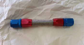
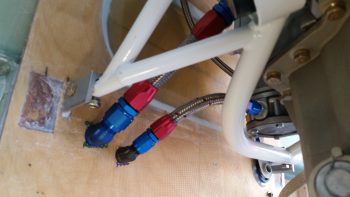
I then gathered up all the accouterments that I needed to make up some engine compartment stainless steel braided hoses with hose ends.  Here’s the first hose I made, which is a -8 hose for the oil heat oil return line.

I then made up a -6 hose for the main fuel line feed to the fuel pump.  One thing I honestly didn’t count on mentally was how SHORT these hoses would turn out based on the confined space of the engine compartment.  I mean, really, the actual length of the hose component of the oil heat oil return line is only 3.7″ long!  Crazy!

Since I had all the stuff out to make hoses I went ahead and terminated some ends ahead of time, like this hose end for the fuel pressure sensor line with the 90° hose end fitting on it.  I was going to do the fuel pump side hose end on the fuel line that goes to the fuel injection servo, but realized I had a head space/timing issue (Browning 0.50 cal reference there) when I ordered the fitting and apparently the fine print said for PTFE hoses only…. oops and dammit!  Ok, another hose end fitting order coming up!

I also attached a hose end fitting to the -8 oil line hose stock and –unrelated– installed the upper fuel spider hose end fitting to the -4 hose that will go from the fuel injection servo to the fuel spider.

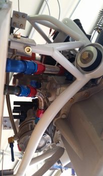
Here you can see the hose peeking out the bottom of the engine.  I’ll of course cut this hose to length and terminate it with a -4 AN hose end fitting once the fuel injection servo is set in its final configuration.

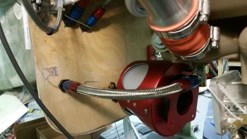
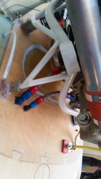
I know the bottom shot is a little blurry, but it’s a decent view of the 2 hoses I just made up today.

And another one from below the engine, at the bottom of the firewall.

I also worked for a couple of hours in assessing the bottom engine area, to include the location of the oil heat sump feed line, the oil drain valve, the fuel injection servo, air intake elbows, and the RAM air intake.  Believe me, there was a lot of musical chairs going on in setting up the configuration (read: major configuration changes) to even begin to work.  I even had to pull out the lower cowling and mock install it a number of times to check for clearances.  Not surprisingly, there is just so LITTLE space for everything to get crammed in there, and I had to resort to a myriad of small, constant changes to even being to get close to the configuration I want.

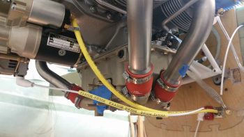
One immediate change (that I was allowing for) that happened after ascertaining the amount of clearance between the lower cowling and the cold air intake tubes is that I moved the alternator and starter power wires to traverse the engine heading forward on the inboard side of the cold air intake tubes vs the outboard/lower side.

So . . . the air induction system should become much clearer over the next week and I will definitely share more as it all unfolds.

I’ll be heading down to Marco’s for a very short 2-day trip and when I return I really want to finalize the firewall aft configurations and get the engine back off the fuselage and onto it’s engine stand.  Moreover, I plan on starting on the canopy and nose at the end of next week.


Chapter 21/22/23 – Configuring firewall

Today was all about getting as much of a jump as possible on the firewall configuration to get that stuff knocked out early.  I did take about half an hour to clean up all the rough edges on the wheel pants’ tire hole reinforcement layups that I did the other day, and then cut, shaped and sanded the bigger layups I did on the back of each wheel pant tire opening.

After reviewing some info on installing NPT fittings I felt I should do my due diligence and check the torque on the 45° AN6 fitting exiting the FT-60 Red Cube fuel flow meter.  It was tight, but I thought it could be tighter.  However, if you’ve seen the install manual there is explicit warnings not to over tighten a fitting on account the transducer’s case might actually crack.  In the AFP-30 Air Data Computer install manual there’s some literature on the FT-60 that states to torque the fittings to 25 ft-lbs.  Since I had a box wrench adapter on a short extension mounted to my torque wrench, I dialed the torque down to 23.5 ft-lbs to ensure I didn’t crack the FT-60 case.  Surprisingly, I was able to get one more entire revolution out of the 45° AN6 fitting… with how much pressure I had to exert to get to that 23.5 ft-lbs (again, remember I was using an protruding box wrench adapter on a short extension… both serving to add a mechanical torque advantage), I’m surprised people go further than that to crack these darn things!

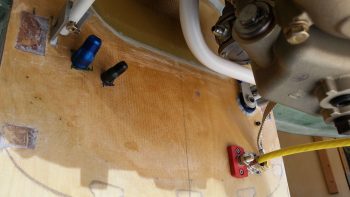
Once I got the aft fitting on the FT-60 squared away, I then did some minor tweaking of the fuel filter and lines to get the filter flat again the front face of the firewall.  I then marked the position of the Adel clamp hole and the fuel line exit point on the firewall.  From inside the hell hole I drilled small holes out using my right angle drill.  I then drilled from the aft firewall side coming back into the hell hole.  You can see the drill bit in the pic below peaking through the firewall and aligned with the fuel line fitting.

Here’s a shot from the firewall side of my initial 2 holes through the firewall for mounting hell hole and firewall assemblies and pass-thrus.

I then took a #10 screw and Dremelled the head of it to create indentions for flox to better grip it.

After drilling out the fuel filter clamp screw hole and then counter sinking the hole, I then floxed the fuel filter Adel clamp mounting screw into place in the hole.  After it cures I’ll layup a small ply of glass over it.

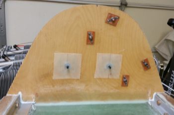
I then took a fair amount of time to figure out exactly where to place the Electroair electronic ignition coil unit on the upper firewall.  I marked off a 1″ Demarcation Zone around the edge of the firewall to ensure I had space for both laying up the fillet glass to the upper cowling mounting overhang, plus room enough to run 1/4″ fuel vent lines as well.  I also needed to stay as far left as possible to give myself room to get the oil filter out for oil changes.

I even called Electroair and conferred with Denny on the location and orientation of the coil unit.  I played around with placing it just aft of where the CS Spar crosses in front of the firewall in the midpoint area of the firewall, and while there’s enough space in that area the spark plug wires would have funky runs to get to the spark plugs.  So, in the end I decided it had to go on the upper firewall, but at an angle.  It sits about 1/4″ above the SD-8 alternator and does very slightly impinge on the Demarcation Zone.

Here’s a closer shot of the mounting location of the Electroair EI coil pack.

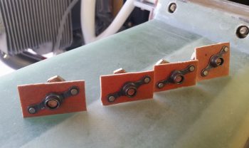
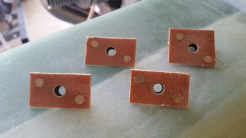
I then got busy making four K1000-4 nutplate assemblies for the AN4 bolts that would be used in mounting the Electroair EI coil pack.  I cut and sanded the phenolic pieces and then riveted the nutplates to the front side of the assemblies.

Here’s an aft view of the Electroair EI coil pack K1000-4 nutplate assemblies.

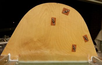
Using the coil pack as a template to keep the AN4 bolts in their exact mounting configuration, I then floxed the 4 nutplate assemblies to the front of the upper firewall.

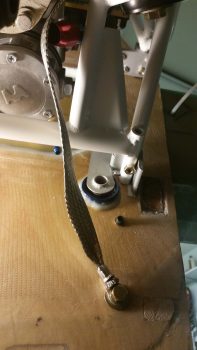
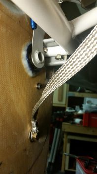
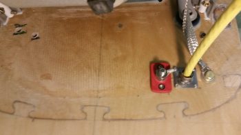
I then focused on installing the B&C Firewall/Engine ground stud and forest of tabs inside the hell hole [the usual configuration for the firewall/engine ground stud and forest of tabs is to have a forest of tabs on each side of the firewall.  However, since I only have two items that require ground on the hot side of the firewall, I forewent installing the forest of tabs on the aft side of the firewall].  Although I didn’t get a pic of it, the engine ground strap is temporarily secured on the engine side where I plan to mount it permanently, so the length I ordered for the braided engine ground strap is spot on.

On the hell hole side of the forest of tabs, I then installed the big yellow ground cable that runs the length of the firewall to the negative ground post on the battery.

I then spent the next hour or so drilling and mounting the big yellow power cable that runs from the starter contactor in the nose battery compartment to the starter through a stainless steel firewall pass-thru.  Inboard of the starter cable, I then drilled and mounted a Blue Sea connector for the Alternator’s B-lead that also heads up to the nose battery compartment.

Although this pic is a bit fuzzy, here is a final view of the firewall configuration tasks that I completed today.  From the upper left hand corner you can see a hole drilled for the Oil Heat oil return line to the engine oil sump.  Slightly lower and to the right of that is the main fuel line that feeds the engine driven fuel pump.  Towards the middle is the #10 (3/16″) screw that I floxed into the hell hole as a mounting stud for the fuel filter’s Adel clamp. Then of course is the electrical firewall pass-thru package, starting from the left with the Blue Sea fitting for the Alternator’s B-Lead, a stainless steel firewall pass-thru with the starter power cable running through it, and then the engine grounding strap that connects to the the firewall ground stud that is opposite the forest of tabs inside the hell hole.

In the pic below I added in the Alternator’s B-Lead which will be paired together with the big yellow starter cable as they both exit the engine compartment via the firewall.

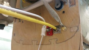
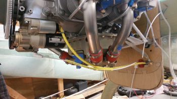
Here’s a wide-angle shot of the major engine component electronics, with the big yellow power cable of the starter, the Alternator’s white B-Lead, and the connected engine grounding strap connected to the firewall ground bolt.

Here’s bit closer shot of the starter and alternator power leads.  Note that the Alternator’s B-Lead is terminated on the Alternator side but not yet at the Blue Sea firewall pass-thru. Also note that the starter lead cable is not terminated yet, and won’t be until I get the Fiberfrax and 6061 aluminum sheet affixed to the firewall.

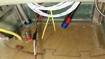
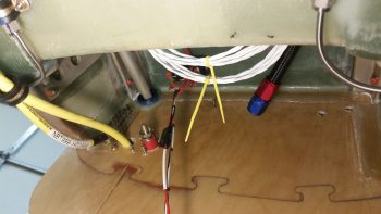
Here’s the hell hole view of all my firewall-based shenanigans. Note that the fuel filter mounting screw is visible in-between the 2 yellow zip ties.

Here’s a little broader view specifically showing the Adel clamp that secures the pair of big yellow power cables.

Tomorrow I’ll continue my firewall configuring tasks.  I should receive some more fittings, so I’ll most likely mount some of those while I’m at it.