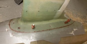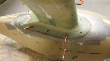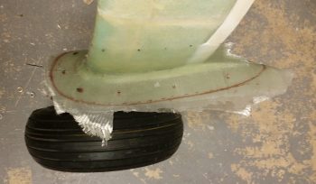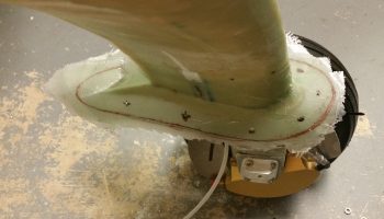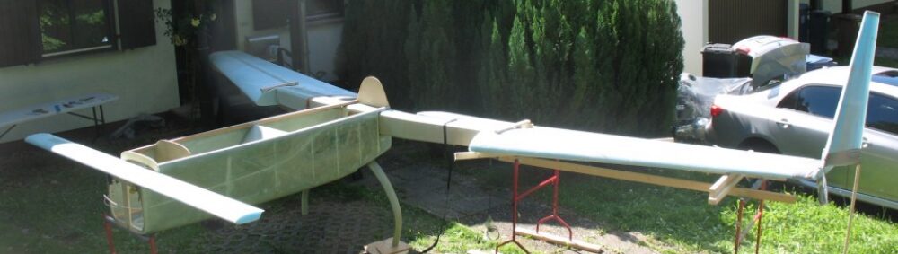
Chapter 23 – Engine mounted!

My goal today was to get the engine mounted.  Having the engine mounted for a bit will again allow me to figure out firewall component placement, firewall pass-thrus, the engine compartment hose requirements, firewall/engine electrical wiring requirements, upper cowling fitting (specifically for canopy/D-Deck angle), initial baffling requirements, lower cowling fit and air intake (fuel injection servo & RAM air) configuration.  Then I’ll remove the engine and mount it to an engine stand.

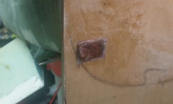
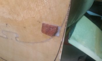
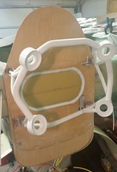
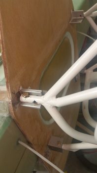
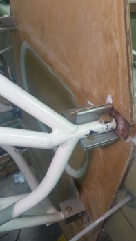
Since A) I needed to remove the engine mount from the engine to get the fuel pump OUT fitting installed, and B) do a final clean and painting of the engine mount, I decided since that since the engine mount was secured in place for the moment that I would trim down 3 of the 4 engine mount stubs to allow for clearance of the firewall face’s Fiberfrax and 6061 aluminum sheet covering.  About an 1/8″ at most getting trimmed off any of the stubs… with the top left already short enough for clearance.

I cut and placed a box that I had just received the second shipment of hoses and hose end fittings from Summit Racing (pretty much finalizing all my hose/fittings orders) over the engine mount/accessory case to protect all of it from sparks and metal debris.
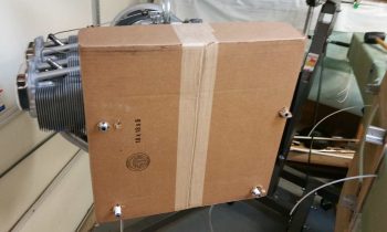
Here’s a closeup of the right side engine mount stubs that needed just a hair trimmed off the front side.
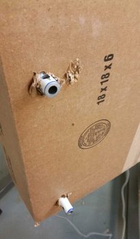
I then spent about half an hour trimming them all up.
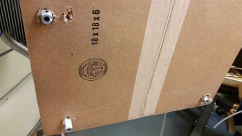
Here the right side stubs are trimmed up and filed smooth.
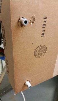
On my errands yesterday I picked up some hardware and some Automotive & industrial strength fast-drying White Rustoleum paint.  I spent a good 30 minutes sanding down the engine mount surfaces with 220 grit sandpaper.  Then I filed off a couple very small weld spatters that I missed before, then washed in hot water and Simple Green.  I then let it air dry.

While the engine mount air dried I spent a good 3-4 minutes shaking the can to mix up the new paint… in painting, preparation is everything, right?!  I then started spraying.  It looked good and sprayed like normal spray paint, but then about 5 minutes into painting the bottom side of the engine mount… apparently my normal spray paint decided it wanted to be a can of textured spray paint.  Within a matter of seconds I had the bottom, bottom right corner and right side of the engine mount peppered with what looked like textured, speckled paint.
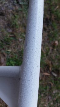
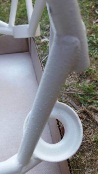
Needless to say I was quite pissed.  My saving grace was that this was fast drying paint, so after about 5 minutes I felt a spot and it was what I considered in it’s green state. Another minute more and I was able to rub down the surface with a paper towel with a decent bit of force to remove the spackles of paint over nearly a third of my engine mount. That didn’t leave it feeling the smoothest, but at least the speckles were nearly completely gone. Apparently a glob of paint or something got caught in the sprayer head…. which I cleared out.  And a number of test sprays in the air to be certain, I continued on painting the engine mount.
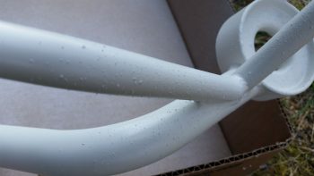
As I waited the requisite 15 minutes for the fast drying paint on the engine mount to dry, I then preheated my kitchen oven to 175° F.  I then popped the fairly dry engine mount into the oven and baked it for 30 minutes.  My goal here on the engine mount paint is of course to have as nice as paint as possible in a reasonable amount of time, but, moreover, I want the engine mount protected against corrosion and for it to be visually inspectable for cracks (thus why no powder coating).
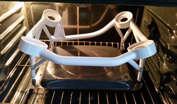
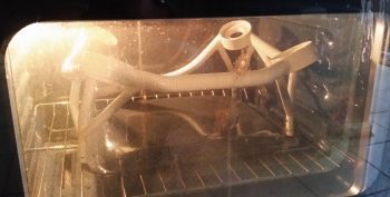
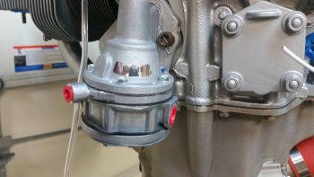
As the painted engine mount baked upstairs, I got to work on the engine mounted mechanical fuel pump.  I took some BEFORE pics from both the right and left sides…
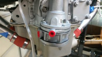
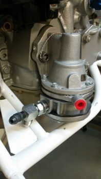
I then mounted the OUT side fitting on the fuel pump, which is a 90° steel fitting that also includes a 1/8″ NPT port straight out for installing a 45° reducer fitting for the fuel pressure sensor line (on the left in pics below).  I also mocked up an AN6 90° hose end fitting (blue & red) to test out the angle for how the fuel feed to the fuel injection servo would run, and an AN4 90° hose end fitting (silver & red) for the fuel pressure sensor hose.  The aluminum AN6 hose end fitting is just to test the angle.  After I verified the angle was the best possible solution I pulled the trigger on a steel AN6 90° hose end fitting from Summit Racing (as well as a 90° 1/8″ NPT to AN3-3/16″ MAP port fitting).

I then installed the fuel pump fuel line feed IN fitting on the right side (as oriented in right pic below).
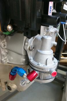
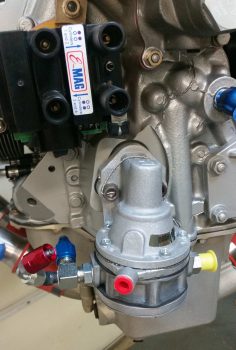
After getting the fuel line fittings squared away, and turning off the stove to let the just-baked engine mount cool, I took off for a bit to run some errands, grab some lunch, and pick up some 1/8″ thick steel angle from Home Depot for the engine mount mount that I’ll weld up for the engine stand.

Upon returning home I then grabbed the cooled and cured engine mount and proceeded to remount it back onto the engine.  [A point of note: the paint on the engine mount is about a 1 meter paint job…. it looks great unless you actually get fairly close or touch it…. if it were an external component I would probably wet sand it and hit it with one more layer of paint, or clear coat even.  Obviously it will be subject to high heat, oil, dust, dirt, etc. in the engine compartment, so I’m more concerned about a robust paint job vs. a sexy one.]
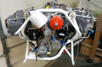
After I got the engine mount remounted to the engine, I then installed the last of the fuel pump’s fittings: the overboard vent line fitting.
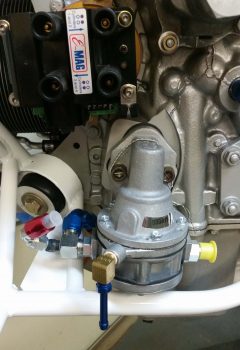
Yet another shot of the fuel pump fittings.
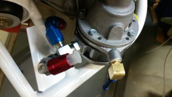
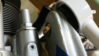
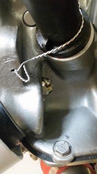
After my airplane building credentials were called into question by a yet to be named Aussie (ok, I give . . . it was Dave Berenholtz!)  Ha!  I had to prove my mechanical prowess by actually getting the amazingly challenging cotter pins installed on the engine mount castle nuts.  Seems like it shouldn’t be that difficult, but the angles and clearances are just killer! (All in fun my friend!).

Here are the top side cotter pins installed in the engine mount bolts and castle nuts.
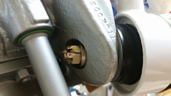
And the bottom left cotter pin installed.  I still have no intentions of trying to do this under cylinder #4 and will swap out that castle nut with a lock nut a bit later.
With the engine mount re-mounted on the engine and everything torqued to specs, there was nothing left to do but mount the engine!  It was go time!

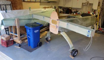
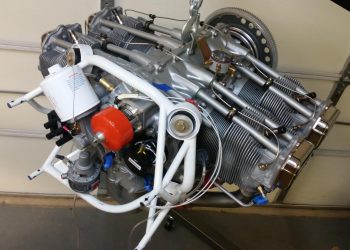
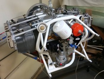
So here she is . . . engine is mounted!!!
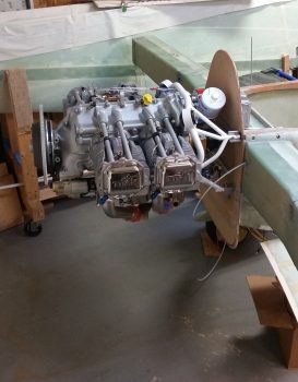
I only had minor issues with getting the last 2 bottom horizontal bolts in place on the engine mount, but after a few minutes of finagling and some light tapping they went right in.
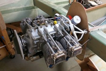
As you can see, even with the eventual fiberfrax and aluminum sheet firewall covering, the clearances are pretty good (by Long-EZ standards) with the firewall.  The only clearance concern I have is between the fuel pump overboard vent fitting and the left aileron control tube…. I’ll have to watch that closely.
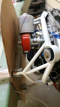
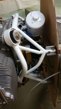
The engine looked a bit small and compact mounted to what I have so far of the fuselage, so wanted to see the cross-section of the engine…. here’s a taste of what that looks like:
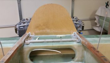
Tomorrow I’ll move forward with my engine data collection tasks that I outlined at the beginning of this blog post, and any related tasks as well.  Next week I plan on starting on the nose and canopy, and hope to have all this engine stuff put to bed for a while… until final engine install crops up.
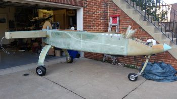
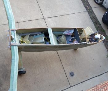
 

Chapter 23 – Turning it around

The fuselage that is . . .

I did some major spring cleaning on my shop today, pulled a ton of stuff that I had buried against the wall that all in all still stole away 2 feet of depth on that side.  Long before I got in deep into custom motorcycle or airplane building, I did a lot of woodworking.  So I have a fair amount of nice wood that all went into the back room awaiting transport down to NC.

I also removed a couple of high shelves and the 4 padded hooks I had up high for the canard, since it won’t be going back up on those hooks.

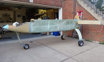
After a number of hours I was finally ready to move the fuselage out and put it back in the shop nose first.  Here’s some pics of that short trek.

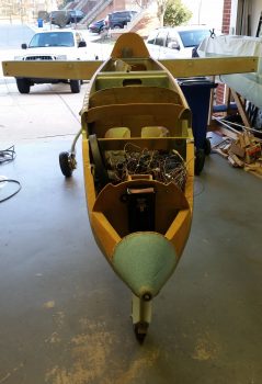
And a head on view of the fuselage’s new setting for a good while.

And an aft view.

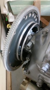
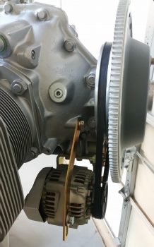
Saturday I received an order from B&C with my engine ground strap, a couple of oil filters and a couple of the shorter Gates 7312 alternator belts.  Before I got to moving the engine around I went ahead and slipped a new alternator belt into place.

Another shot of the new alternator belt in place.

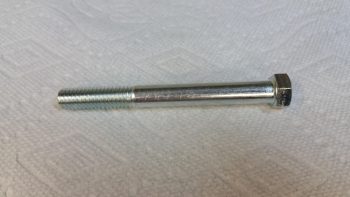
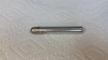
Before I mounted the engine mount to the engine, I reviewed my notes.  One Canardian had a trick he swears by using a “silver bullet” . . . You start with a standard 7/16″ bolt.

Chop the head off and grind it into a bullet looking pin.  Now, he said 2-3″, but I don’t know what engine he was installing.  The concept is simple, use the silver bullet to align the last two Lord rubber vibration dampener assemblies (one at a time) to the engine mount holes and then press the actual bolt in behind it, pushing the silver bullet out the other side.

The concept works great, but for an 320 case I think 1.5″ is the max length you can use since there’s not enough clearance on the other side.  The one I made is about 2-5/8″ long and would get blocked from coming out the other side by some part of the engine.

So I didn’t use the silver bullet, but installing the engine mount to the engine versus mounting the engine to the engine mount with the latter pre-mounted to the firewall made it EZ enough anyway (albeit, still a ton of the usual fiddling about).

I had bought 4 castle nuts to use but I will say that I’m wimping out on using these at every point, especially under cylinder #4…. no way.  So I put a mini-order in with ACS for two AN363-720 lock nuts as called out for in the Long-EZ plans.

Also, for a newb like me, I was concerned at first that my AN7-35A engine mount bolts weren’t long enough since I couldn’t get a thread showing until I compressed the installed dampener mounts a bit with squeezes clamps.  However, in the end I needed to put 2-3 washers on to keep the cotter pin hole within the castellated part of the nut and not end up well past it when all was properly torqued (450-500 in-lbs).

I really don’t like doing things twice if I can avoid it, and I was going to make every attempt to make this engine mount install onto the motor my last one.  But alas, it was not meant to be.  While doing a good round of patting myself on the back for a job well done … haha! I noted that fuel pump looked awfully close to the engine mount… REALLY close as a matter of fact.  Well, when I tried to thread in the FUEL OUT fitting onto the pump the engine mount wasn’t having any of it.

Thus the engine mount will have to come off at least once more AND I have to buy another 90-150 degree extended fitting (which means steel now) to get by that engine mount reinforcement tube.  It will be a really tight fit, but if the fitting goes in first I don’t foresee any clearance issues . . . again, just all really tight (but then again, we’re talking about a Long-EZ here!  Everything is really tight clearances…)

Tomorrow I’ll work more on getting the engine mounted to the firewall to get a ton of much needed data . . . which, as was evident tonight, I already am!


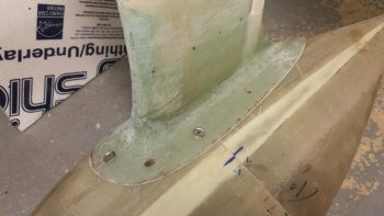
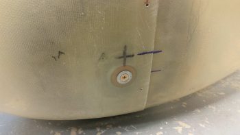
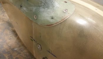
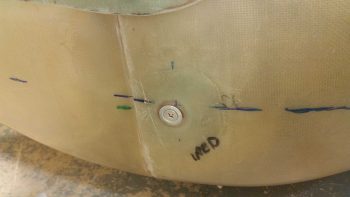
Chapter 9 – Wheel pants final glass

I had to run some errands today so I didn’t get into the shop until late afternoon.

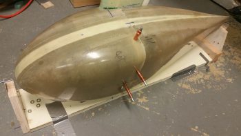
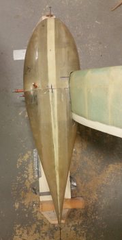
My goal today was to finish the last bit of scheduled layups on the wheel pants.  So unless some odd requirement pops up for extra glass on the wheel pants, this should be the last of any fiberglass layups that I’ll need to do on these wheel pants.

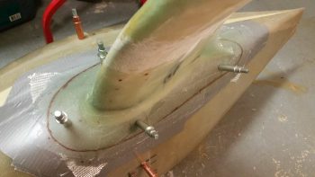
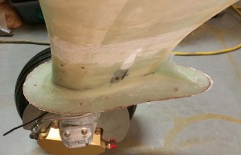
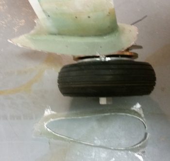
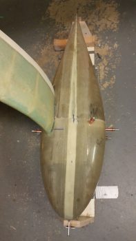
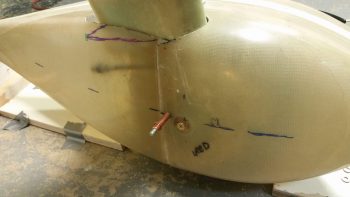
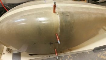
I started by assessing the tire clearance with the left wheel pant.  I needed to do some judicious trimming in the front and along both sides, but the back side was a completely different story.  Since I had originally miscalculated the forward positioning of the front wheel pant, the result was that I ended up cutting the aft side of the wheel opening way too big, with over an inch extra gap for the tire.

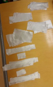
Thus, as far glassing was concerned, my goal was to reinforce all the side and front edges with 2 plies of BID, as Gary Hertzler calls out for in the install instructions.  What Gary doesn’t specify is the width of the reinforcement glass, so I planned for 2 plies of BID at 3/4″ wide.  As I said, the aft edge was a different story and needed a fair bit of glass to fill it back in. So I prepregged all the glass and got started.

I then laid up the interior reinforcement BID for the left side wheel pant (shown farther below).  As the left side glass layups cured, I then assembled the right side wheel pant onto the gear and mounted it using nothing but screws (no Clecos).

I then assessed and determined the wheel opening spacing requirements with the tire.  I cut and prepregged the BID for the right side just as I did on the left side, and then laid up the reinforcement BID around the wheel opening in the right wheel pant.

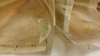
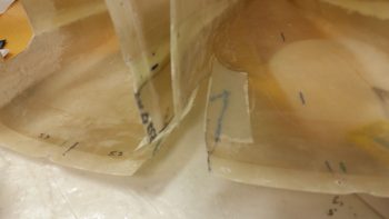
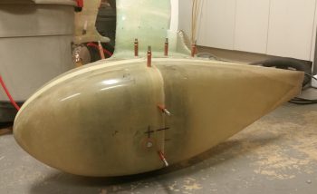
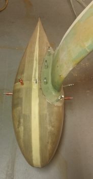
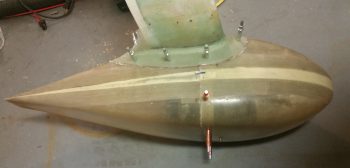
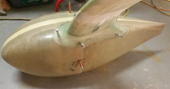
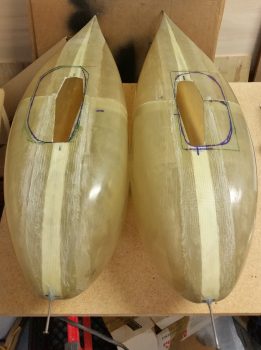
Here’s a shot of the left and right front wheel pant halves’ tire opening reinforcement BID.

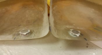
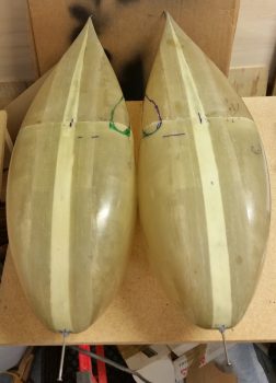
And the same thing on the aft side, only with some filler glass on the aft end of both rear wheel pant halves.  As you can see, the aft side wheel pant tire opening on the left required a lot more filler glass than the one on the right side.  Once the filler glass cures, I’ll cut it in an oval-type/rounded-corner rectangle fashion for wheel clearance.

After the last bit of glassing on the wheel pants, I then took a break for some chow.  When I returned to the shop I then spent about 2 hours organizing and cleaning the shop in prep for bringing my wings back inside, flipping the fuselage around so that it’s situated in the shop nose in… opposite of what I have now.  In addition, tomorrow I plan on mounting the engine to the firewall to mockup the firewall pass thru fittings, hoses and electrical connections.


Chapter 9 – Another pant day

I started out the day by updating my wheel pants (or “spats”) task list before heading down to the shop.  My plan was to get to the point I could knock out a few layups on the wheel pants then roll into finalizing the shop reorganization… with the wings inside and the fuselage having done an about face.  But that didn’t happen.
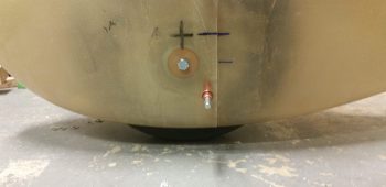
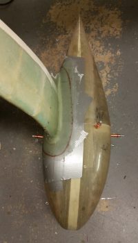
What did happen was a whole lot of mini-tasks getting completed on the wheel pants, which of course has moved the completion bar to I’d say the mid-90% area (excluding finishing of course).

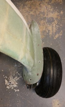
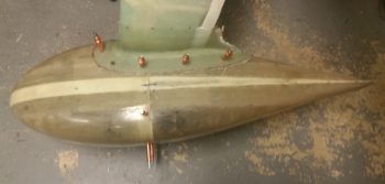
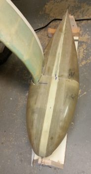
My first task of the day was to trim down the Gear leg to wheel pant bonnet fairing on the aft side of the bonnet.  I just couldn’t pass up the opportunity to make a swoosh-style fairing here because when I see canard aircraft with wheel pants without this swoosh fairing  . . . well, something is just missing mentally for me.  So in they went.

Obviously here is the before-trimmed shot.

And then after I trimmed down the jagged swoosh fairing edge.

Here we have the right side swoosh fairing after I trimmed it down.  I would like to point out that these are initial trimmings, and I’ll dial them in most likely when I finish the wheel pants to paint.

I then set my sights on drilling out the left side bonnet’s front 3 mounting holes for #10 screws.  After drilling the front hole I set a #10 screw in place with a narrow Tinnermam-style washer.

I then did the same after drilling the outboard mounting hole.

With the front side screw holes drilled out (remember, the aft end gets CAMLOCs) on both the left and right wheel pants and bonnets, I then pulled the wheel pants off.  I then sanded down the interior edge of the tire openings for the upcoming 2-ply reinforcement BID those will get.

I then laid up 2 plies of BID on “top”  (the inboard sides) of the outboard support doublers. Again, this was due to delams caused by the extreme angles from the sides of the doublers to the “top” surface, and something I had a good notion might happen.  No worries, small EZ layups and a little flox and they’ll be right as rain.

[Although I forgot to take any pics, I also laid up a ply of BID over each line of flocro that I used to hold the stainless steel brake lines into the gear fairing after bending them out to flare and terminate the ends.  The bonnet layups covered the bottom 2/3rds of the channels, but the tops were just bare flocro on the inboard side of the gear legs].

Since my plane has the wide main gear fairing and thus a longer bonnet, I then added a ply of BID on the insides of both aft wheel pants where the CAMLOCs will get mounted. The area where I added the BID is much lighter glassed than the more robust areas of the wheel pants.

As the glass cured I then got to work sanding and shaping the edges of the wheel pant bonnets that are now permanent fixtures on the gear legs.  In addition, I spent about 10-15 minutes per side digging out the transition-fillet-creating Play-doh from under the bonnet.

Here’s the right side bonnet cleaned up and sanded.

A few hours later here are the cured and trimmed support doublers.

And here’s a shot of the K1000-3 nutplates I riveted into place as the glass layups were drying.

After all the layups had cured and I pulled peel ply and cleaned them all up, I then mocked up the left wheel pant using only screws… no Clecos.

Here you can see the top front 3 screws in place.  In actuality I need to get some more screws since only the outboard centerline screw is the right size #10 screw, and doing the lion’s share of the work.  The front and inboard are #8 screws that I used to show visually how it all would look.  BTW, if you’re wondering why I ended up going with #10 screws, it was simply a matter of visual balance with the CAMLOCs, whose studs have the same size head as the #10 screws.  With 5 screws total for each wheel pant, the weight increase is minuscule going with #10 screws vs #8’s.

I did what I could to countersink the 1/4-28 side mounting screws, but I will need to pick up an actual 1/4″ 100° countersink from ACS to finish the job.  Although the Tinnerman washer sits just a hair proud, this shot of the outboard mounting screw still gives you an idea of how it looks.

Here’s a shot of the screws from the inboard side.

And here’s a shot of the inboard 1/4-28 mounting screw with Tinnerman washer.

Tomorrow I’ll check and make any required adjustments for tire clearances.  After/if any cutting is required, I’ll then layup the 2-ply reinforcement layups around the perimeter of the tire openings.  After that, the wheel pants will be completed except for the additional mounting hardware that needs to installed (screws, CAMLOCs, etc.) and finishing of them to paint.


Chapter 9 – Wheel spats finished 2.0

My buddy LG taught me some trivia last night when he kept using the term “wheel spats” for my wheel pants.  We looked it up online and sure enough, wheel spats is another term used for wheel pants . . . apparently a bit more in Britain.  I actually like the term better so I will begin using it as a part of my lexicon! ha!

Last night was a late night with quite a bit of socializing going on, so let’s just say I was moving a bit more slowly this morning.  I took a couple hours to do some research and finalize my last couple of orders to acquire all the hoses, fittings and fire sleeve I will need to roll my own engine fuel, oil, MAP and sensor hoses.  I also pulled the trigger on some more MGS epoxy and some CAMLOCs for the wheel pants.

I then spent a couple of hours reconfiguring and cleaning out the shop.  My wings have been outside in my driveway (covered) on the wing dolly for a good number of days since I started working on installing the wheel pants.  I want to get them back in the shop, but more against the sidewall and out of the way.  I will say it’s great to have the wings built, but they do really get in the way when you don’t need them.
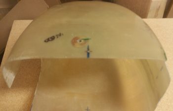
I then started in on the wheel pants.  First off I’d like to note that on the profile shot that there is clearly no smile.  To be fair, I widened these wheel pants 1″ at the widest point, and with the benefit of hindsight –again– I think that 3/4″ would have most likely been plenty enough to do the trick.

I’d also like to apologize ahead of time for the crappy quality of a number of these pics… I was in a rush and unless I blow up each pic on my phone, I don’t realize often how bad they are until later.  I guess it’s because they essentially make camera phones for Millenials to take selfies rather than actual pics…. at least for my phone because it just does not have a camera that likes to focus very well…

Moving on.

Now, of course it’s my biased opinion, but since the 400×5 wheels/tires –thus the subsequent wheel pants (or wheel spats)– are significantly smaller than the 500×5 wheels, then my widening the wheel pants hasn’t seemed to make them overtly fat in appearance. Again, IMHO.

I started out my short work evening by marking the wheel pants’ bonnets for trimming.  I originally had planned on making the flange of the bonnet 1.6″ wide, but that was a bit too narrow so I settled on 1.8″.

I also switched around the screw locations on the front side from 2 each side forward of the wheel pant split to only 1 each side with a lone screw at the front center position (the bold dot on the front flange “corner” <pic below> is a screw position that I had originally planned for, but that I eliminated from the lineup).  Going with 3 screws up front vs. 4 provided me with more equidistant spacing for the next 2 fasteners (CAMLOCs) aft of the split.

Now, the fact that I have 2 CAMLOCs aft of the split on each side is change #2.  Sitting upstairs on my couch as I planned out all these fasteners, I just didn’t really realize how long the side of the bonnet flange was until I was actually downstairs in the shop looking at it…. this means I’ll be short 2 CAMLOC receptacles in the order I submitted today.  Oh well, that’s why I like to build stuff like the wheel pants as early as possible to flush out all these minor hardware issues, etc.

As a point of note, the total hardware for each wheel pant is 5 screws and 9 CAMLOCs…. of which 4 screws and all 9 CAMLOCs will need to be unfastened to remove the aft side pant for checking/filling tire pressure, maintenance, etc.

After I got my screw/CAMLOC locations dialed in, I carefully drilled a hole at each location… adding Clecos as I went.

Here’s the inboard side of the left wheel pant bonnet, marked for trimming and holes drilled at the fastener locations.

I then spent a good 10 minutes extracting the wheel pant halves from the iron grip of the bonnet.

Here we have the inboard view of the untrimmed bonnet.

And the same view, only with the bonnet trimmed with the Fein saw.

And a couple more shots of the trimmed wheel pant bonnet on the left gear.

Since it was later in the evening, I wanted to get my loud Fein saw cutting shenanigans out of the way as early as possible, so I immediately headed over to finish up the right wheel pant bonnet.  I started off by measuring and marking it in the best emulation of the left wheel pant bonnet as possible.

Then I drilled the screw/CAMLOC holes and Clecoed those.

Here’s an inboard view of the marked, drilled and Clecoed right wheel pant bonnet.

I then trimmed the right side wheel pant bonnet with the Fein saw.

Here’s the outboard view of the trimmed right wheel pant bonnet (again, sorry for the pic).

After I had made my loud noise for the evening, I excitedly got to work reassembling the wheel pants onto the trimmed bonnets.  Hoo-ah!  I’ve been waiting for this point for a LONG time!

I first reassembled the left wheel pant, installing both side mounting screws and all the Clecos.

And then did the same thing for the right side wheel pant.

I would like to point out that these bonnets are in their rough cut state and there are obvious minor differences between the right and left sides.  And while I’m realistic in accepting that both sides won’t match perfectly, I will shape them as close as possible to minimize any differences between the two…. and I honestly think the resulting differences in shape will be so minimal that it will be hardly noticeably out on a flight line.

The bottom line is that I LOVE these wheel spats (hehe), and man do they make this bird look sexy!  As I mentioned before, I still have a few more minor tasks before I can claim that they’re totally complete, but we’re pretty darn close.

Woo-hoo!


Chapter 9 – Final Brake Line install

Finished!  As are all the major install steps for the wheel pants . . .

I started off today checking the alignment on the right wheel pant with both the inboard and outboard doublers’ glass cured.  I need to reglass the top of each outboard doubler for some minor air pocket/delam issues I had on each with such sharp bends of the glass (even though I weighed them down during cure).  Regardless, the doublers are solidly in and the re-glassing a minor issue.

With the Clecos, outboard and inboard mounting screws in place the right wheel pant was dead on parallel with the A/C centerline marks.  However, what is a slight ailment to the left wheel pant (below) in windage, my right wheel pant suffers from a very slight 0.1″ difference in elevation between aft/tail wheel pant height off the jig and the nose.  So, while the nose nail comfortably rests on the jig, the tail nail hovers –again– about 0.1″ above it. Of course, this is all imperceptible if no jig is present.

Here’s a shot the right wheel pant with the outboard mounting screw installed.

As well as the inboard mounting screw installed.

The left was not bad at all, however it was about 0.1″ off wheel pant nose vs. tail as compared to parallel to the A/C centerline marks.  Not a big deal, and really took some work to find it against my marks (Instead of moving the entire wheel pant jig left or right, I simple went off how far from my A/C centerline mark the nail on each end was.  Say, if both were 0.3″ from the mark it’s the same as being right over the mark on each end…).

I tried to capture this with pics, but the cell phone’s camera is off to one side, so by looking at the angled sides of each jig upright you can see if I’m straight overhead (the two angled edges should be equal).  I took a number of pics but never got exactly overhead… the bottom line is I’m about 1 nail widths off between front and back on the left wheel pant.

Of course 0.1″ is not at all noticeable on just looking at the pant, and I doubt has very minimal –if any– impact on aerodynamic performance.  With the wheel pant locked in position with Clecos, inboard and outboard screws in place, I’ll take the 0.1″ off and press on.

Here’s a shot of the outboard mounting screw installed on the left wheel pant.

And the inboard screw as well.

Two things had to happen before I would get to the point that I was ready to glass the bonnet onto each wheel pant.  The first was a WANT and was related to making the second REQUIRED task a little easier . . . attaching the 3/16″ SS brake line to the 9.25″ SS braided brake line coming from the brake caliper.

I started by removing the lower part of the gear leg fairing that was situated inside the wheel pant.  With both wheel pants in place I marked the gear leg opening of the wheel pants to depict the no-kidding line where each wheel pant intersected the gear leg.  Just to ensure that I had no clearance issues pop up on me, I dropped the line down approximately another 1/4″ as my cut line.

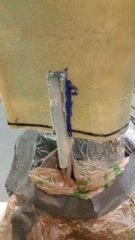
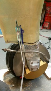
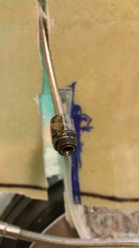
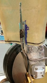
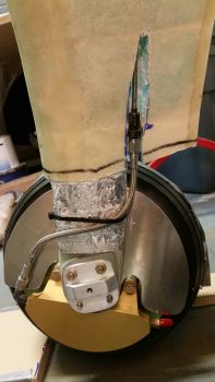
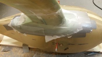
I then removed the extraneous portion of the gear leg fairing that would have been inside the wheel pant whenever the wheel pant was mounted.  Not only does this give me more maneuvering room and space inside the wheel pant and saves a tiny bit of weight, but the main thing is that it allowed me access to the brake line that runs inside a plastic tube inside the gear leg (visible just aft of the gear fairing mid-point in the pic below).

I then eyeballed how the brake line tube plastic conduit traveled up through the gear leg fairing.  Now, hindsight being 20/20, if I had known then what I do now, I would have simply ordered a 6″ long -3 braided SS brake line . . . but I didn’t, and these things are expensive as all get out.  I don’t normally like burying things that are a probably a good idea to have access to when there’s a potential spot for leaks (aka “fittings”).  So if required, I’m making this so I can simply cut out a rectangular piece of glass and have the fitting right at my disposal… it won’t be pretty, but it will be accessible, in a PITA sort of way.

Optimal? No.  Am I doing it? Yes.  I figure unless there’s a leak, it will most likely serve as any other brake line does in these birds and become a distant memory of the oddball installation.

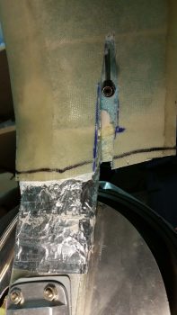
I cut out a channel a few inches high to gain access to a good portion of the 3/16″ SS brake line that I had just ran last week into the hell hole.

I then managed to get the plastic tubing conduit cut away.  What I was after here was enough length of brake line to bend it out, flare it with a fitting end attached, and then stow it away (bend it) back into the gear leg fairing.

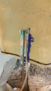
With the length of the -3 hose, I needed access to a bit more tubing to cut and flare the end, so I cut a narrower channel going up the gear leg fairing.  This allowed me to pull enough of the brake line out to cut it, then flare it.

Which is exactly what I did, with just the barest amount of space enough to get the crimping tool on the end of the 3/16″ SS brake line.

But I prevailed in the end, with a pretty decent flare if I say so myself (smile).

I then shoved it all back into the ugly gaping channel that I had just made on the inside of the left gear leg fairing.

I then did the same thing with the right brake line on the right gear leg fairing.

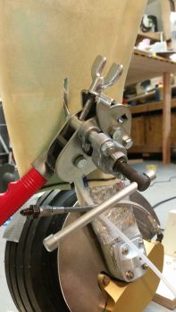
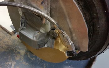
Then, just as I did on the left gear leg, I connected the 9.25″ -3 braided SS hose to both the brake caliper fitting and the (now) in gear leg fairing 3/16″ SS brake line fitting.  This finishes the brake line run from wheels all the way to master cylinders.

I forgot to snap any pics, but my next task was to whip up some thick 30/70 flocro paste (heavy on the micro) and embed just the 3/16″ SS brake line in the gear leg fairing.  This was after I wrapped the fitting in protective plastic wrap and covered it with a piece of electrical tape.  To be clear, the fitting did not get any flocro covering it, just the brake line tubing.

While the flocro cured, I developed my layup schedule for the wheel pants bonnet layups, and then got busy cutting a bunch of BID.

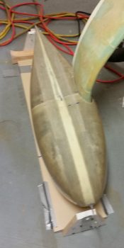
After having craft hour with Play-doh making the fillet at the intersection of the main gear leg to wheel pants (this was after re-reviewing Terry Schubert’s very informative presentation on drag) I then proceeded —for the next 5 hours!— to layup the wheel pant bonnet on the right wheel pant . . .

And the left.

I then peel plied the bonnet layups.  Allthough I still have some reinforcement layups to do around the wheel openings and a ply or two on the face of each outboard reinforcement doubler… and let’s not forget the drilling and installing of nutplates, screws, and CAMLOCs… clearly the lion’s share of the wheel pants install is COMPLETE.  Thus, I’m calling my 3-DAY . . . er, ah, 4-DAY BLITZ a success!

Tomorrow I’ll be prepping to have a good friend come to stay overnight and we’ll be heading out for social hour with some other friends…. so not a lot of build work will get done.  I’m going to celebrate finally getting these darn wheel pants installed!


Chapter 9 – 3-DAY BLITZ…day 3

Well, as with all currencies in the world, including building currency, we must account for inflation . . . so, unfortunately, I see my 3-DAY BLITZ turning into a 4-DAY BLITZ…. ha!

I need those couple hours of cleaning up the firewall that I spent on Day 1 back (wink). And what I didn’t count on today was everything about working the inboard wheel pants mounting brackets taking 3x longer than I had anticipated.  I figured 1.5-2 hours to finish the brackets, but it ended up taking well over 3.5 hours to finish them.  I am of course super happy that they are done and in the history books.

Starting on the right gear leg, the top 2 gear bolts were tight enough that I could get the temp thin-line nuts off the bolts.  However, the bottom two just spun freely, so I had to Dremel a slot in the end of each one to enable using a slotted screwdriver to remove each nut.

As an aside, when I chose the lengths of the axle bolts I had in mind a wheel pant bracket of 0.050-0.060″ thick, not about twice that which I have on these brackets.  So, the wheel axle bolts will need to be swapped out for longer bolts, but LATER since I’m only concerned about getting the wheel pants on at this point and time.

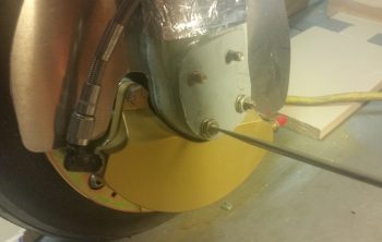
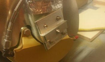
Once I got all the securing hardware off the axle bolts, I was then able to test fit the right inboard wheel pant mounting bracket.  I will say that looking at the pic below, for some odd reason the upper right bolt hole came out a good 1/16″ out of position, so I widened the hole into an oval shape to get the bracket to fit into place.

I then marked up the bracket for cutting and shaping.  I used my power miter saw, Dremel, hand files and sandpaper to get the bracket that started out looking like this . . .

To this state.  I think a fair bit easier on the eyes, eh?!  I still need a good half hour on each bracket to do a final clean and prep, perhaps even Alodine, which I’ll do when I replace the axle bolts with the final set for the final time.

I then started in on the left side.  This time it was the upper pair of bolts that required me to Dremel a slot into them in order to remove the temp thin-line nuts I had in place.  And I’ll be darned if I didn’t have the top right (as pictured below) bolt hole about 1/16″ off!  Not sure what is going on there (maybe I lose interest on bolt hole placement after the third hole and my mind starts wondering . . . haha!)

Here’s the left side inboard wheel pant mounting bracket after I cleaned ‘er up a bit. Again, not bad, but it will need just a bit more to reach its final clean state.

I then spent a good hour dialing in the final position of the right wheel pant.  My initial swag of the outboard vertical alignment of the mounting screw position –which is supposed to be 1.5″ forward of the pant seam (get it?! … ) — was off a bit and I needed to remove about another 0.5″ of material in the U-shaped gear leg cutout on the forward half wheel pant.  This enabled to move the entire wheel pant aft, as I noted after having to move my jig assembly aft a couple times when the tail of the wheel paint was being physically restrained from free movement by the aft jig upright.

Well, removing material from the top gear strut area alone wasn’t the only requirement of course for getting the entire pant moved aft, since there’s quite a large protrusion called a TIRE at the bottom that had its say as well.  So this whole machination of course called for some tire hole lengthening and just a hair of widening to allow the front pant half to move aft, keeping the vertical split line perpendicular to the ground.  Of course I eventually got it, was able to get the Clecos in AND align the wheel pant in both pitch and yaw.

Here’s an aft shot of the right wheel pant in its aligned positioned.

I then got to play “whack-a-bolt” for the first time on the inboard side of the right wheel pant.  With the short “whack-a-bolt” pointy thingy installed in the right inboard mounting bracket (which I threaded into place before I aligned the wheel pant above), I then gave it a sharp rap with a rubber mallet.  As you can see, it does leave a very nice visible mark to let your know where to drill.

With my first inboard mounting screw position known, I then needed some 1/8″ thick inboard support doublers (I call them spacers, but I want to keep my verbiage understandable….!).  BTW, these wheel pants work great with 1/4″ doublers on each side… little did I know what can of worms I was opening by placing all my widths on 1/8″ increments.

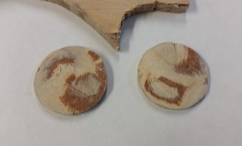
Thus, since I didn’t have any viable 1/8″ material on hand, I then decided I need to make some 1/8″ thick support doublers.  I cut out a 1″ circle by using a socket with a diameter just a very scant over 1″, then used my Saber saw to cut out the disk.  I cleaned it up with my hard sanding block before using my nifty German saw to cut them right down the middle.

With the resulting interior surfaces looking like this (anyone thinking thick flox . . . cuz’ I am!!)

But the thickness were right in the ballpark I needed, so clearly these little dogs can hunt!

I radiused the edge of the 1″ diameter support doubler disk and sanded the inside edge of the wheel pant A LOT.

I then floxed the 1″ round ~1/8″ thick support doubler in place and covered it with 2-plies of BID.

I then set my sights on the left wheel pant and worked on it for a good hour or so as the layup on the support doubler cured.  I then drilled out the hole in the center of the doubler to 1/4″ and Voila!  She works!

I then set the “Whack-a-bolt” in the VANs outboard wheel pant bracket and reassembled the right side wheel pant with the 1/4″ inboard mounting screw in place.  I ensured the alignment looked good and left the right wheel pant alone for a bit while I focused on the left side.

Getting the left side wheel pant to its final alignment state took about 20 minutes of course since I knew I had a bunch of material to remove on the front wheel pant half and wasn’t as gingerly in my initial removal of the wheel pant fiberglass.

I then did “Whack-a-bolt” round 2 on the inboard side of the left wheel pant, floxed and glassed the 1/8″ support doubler in place, drilled out the center hole to 1/4″, then tested the 1/4″ mounting screw and doubler placement by reassembling the wheel pant and aligning it (after it cured of course).

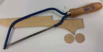
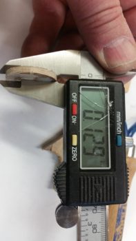
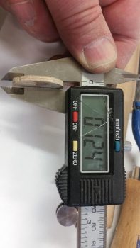
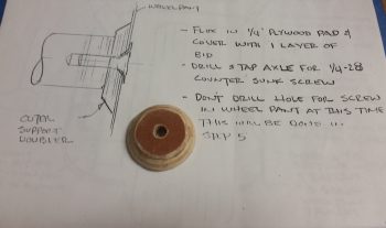
By this point I had already played “Whack-a-bolt” round 3 on the outboard side of the right wheel pant.  Here’s the 0.4″ thick support doubler I made up for the right side wheel pant. To get the correct thickness I cut out a 1.3″ diameter disk of 0.375″ (3/8″) thick plywood (dense), removed the top ply of the plywood layers for a resulting thickness of ~0.34″. I then simply 5-min glued a 1″ diameter disk of 0.063″ (1/16″) thick phenolic to the top of it. I then continued the taper of the lower wood disk onto the phenolic to come up with my ~0.4″ thick support doubler.

I then drilled out the 1/4″ mounting hole on the right outboard wheel pant, installed a greased up bolt through the support doubler that I had floxed to the inside of the forward wheel pant.  I then reassembled the entire wheel pant, with Clecos holding in place and the inboard 1/4″ mounting screw installed.  I then aligned the right side wheel pant as the outboard support doubler flox cured.

I then repeated the process for the outboard support doubler on the left side, although it required a 0.5″ thick doubler [this makes sense since I could tell while determining and marking the wheel openings that the left wheel pant was slightly larger than the right]. I first played the final round of “Whack-a-bolt” (as shown below), disassembled the wheel pant and drilled out the 1/4″ hole where the point thingy left its mark.

[Some points of note on my wheel pants: I followed a combined set of instructions, primarily based on Gary Hertzler’s original instructions as interpreted by Wayne Hicks… with some smattering of Bernie Siu’s processes here and there.  Although I don’t see an issue since the 3/8″ gap on the top is the determinant measurement and I kept the wheel pant sides parallel to the wheel side…. however, on both side wheel pants my outboard mounting bolt hole is 1.2″ lower than the center waterline.  This actually appears to be in line with what is shown –but not stated– in Gary Hertzler’s installation instructions.  One final point on this is that my outboard mounting bolts are 0.8″ lower than my inboard mounting holes on both wheel pants.  Thus, the outboard side is canted up a bit if looking at the wheel pants from the head on view…..technically, since I don’t see anything that looks off.]

Then, just as on the right side, I floxed the outboard doubler in place and used a greased bolt to hold it in place tightly against the VANs outboard wheel pant bracket (taped up to protect against nasties).  I then reassembled the wheel pant with Clecos and the inboard 1/4″ mounting screw while assuring it was aligned both in pitch and yaw.

Here’s a final overhead shot of my left wheel pant with the outboard support doubler floxed in place and clamped down with a bolt into the outboard mounting bracket.

I let the flox cure (I used fast hardener) for about 1.5 hours before I removed the wheel pant and laid up a ply of BID over the outboard support doubler.  With all my support doublers then glassed, I called it a night.

Tomorrow I’ll have some fun with Play-doh as I finish the last major step on the wheel pants installation: fabricating the gear leg bonnet.  I know I missed finishing my wheel pants within my 3-DAY BLITZ, but hey, if I can knock them out in 4 days, with a few minor outstanding tasks to do… I’ll take that any day!


Chapter 9 – No smiles allowed!

3-DAY BLITZ: Day 2

By “no smiles allowed” I am of course referring to the “smiles” that wheel pants that are too narrow often end up with…. a common occurrence in the canard world since wheel pants made primarily for RVs end up looking a bit different on our birds with gear bows.

The cure for this, at least according to Wayne Hicks (and after today, I’m a TRUE believer) is to simply widen the wheel pants… which I did.  Of course we discussed this, it’s just been quite some time since I’ve done or posted anything on wheel pants.

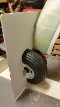
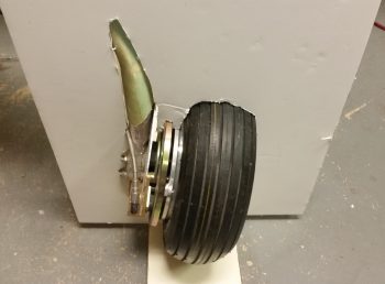
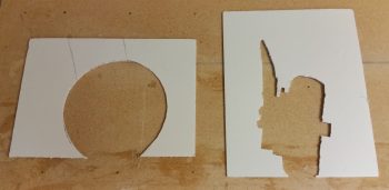
I started off today doing the thing that for some reason I dreaded the most for the wheel pants installation process: making the cardboard cutout templates of the wheel & gear.  Of course, just about like anything else once you actually get going on it then it’s not that bad… such was the case here.

I started at the front of the wheel and moved aft, incrementally removing any piece of poster board that prevented me from moving it aft.  Here a shot of round 2 or 3 of poster board removal.

After about half an hour of slowing cutting and hacking away parts of the poster board, I was finally finished with my first poster board gear cutout template.

Here’s a shot from the front . . . and as you can see, my template wouldn’t win any contests!

Of course the one from the side was infinitely more easy and I had it knocked out in 10 min at the most.

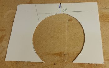
These cutout templates are used to determine the front/aft edges of the tire hole, the right/left edges of the tire hole and the location of the cutout for the gear strut.  They pretty much give you everything you need for the tire cutout, but for the gear strut cutout, what it doesn’t provide is the angle.

I started with with the side silhouette cutout and marked both the vertical axle line (in blue) and the 3/8″ minimum clearance gap (in green) between the top of the tire and the underside/inside top of the gear pant [which is why we ensure the tires are at max PSI].

I started with the right wheel pant and marked the front/aft tire cutout lines and the location and width of the gear strut.

Here’s a more direct down view, showing that the top of the wheel pant is aligned with the 3/8″ line to ensure inside top clearance with the tire.  Once this is done, it automatically dictates how much of the tire will show through on the bottom.  To get the wheel pant aligned properly nose/tail up or down (waterline), I made pencil hash marks at 6″ in the front and aft sides on the table, and aligned the nails with those marks.

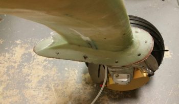
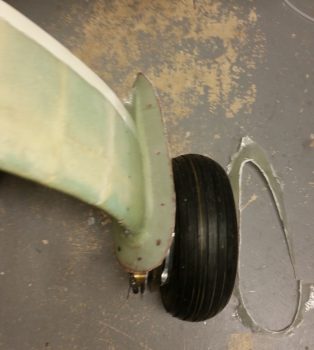
I then broke the wheel pants into its 2 pieces and used the front piece to determine left/right edges of the tire cutout (the one shown below is the left side wheel pant).  As you can see, with our gear struts and wheel assemblies taking up so much room inside the wheel pants, it really pushes the tire wheel pant exit far outboard.

Before making the final tire exit marks on the wheel pant, I verified clearances and dimensions by drawing the outline of the wheel pant onto the cutout template.  This really does help figure out all the wheel pant mounting, since in my case I had planned on using a 1/4″ wood spacer on the inboard side of the wheel pant as called out for in the installation instructions.  However, even though I widened my wheel pants I still felt the outboard wheel pant side was too close to the wheel/tire.  Thus, I changed the plan and went with a 1/8″ inboard spacer to drive the entire wheel pant outboard 1/8″.  Not a lot, but every bit helps in ensuring NO SMILES on the side of the wheel pant!

I then marked the location for the gear strut width-wise.

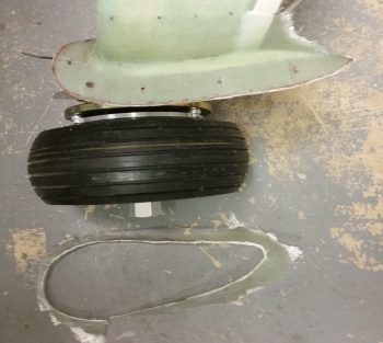
Here are the initial markings for the tire cutouts on the bottom of the wheel pants.  If you want to know what side is what, just imagine the plane flying upside down.

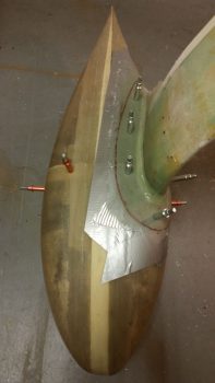
And here are the initial markings for the landing gear strut holes.

Since my inboard wheel pant mount is 1/2″ thick, and the new thickness for my inboard wheel pant spacer is 1/8″, I added a hair for flox and glass and made a foam spacer for each inboard side (R/L) at 0.65″ thick and taped them in place.

After determining and setting wheel pant jigs to match the CL of the aircraft, I then spent the next 4+ hours doing the iterative, trial-and-error: test fit-mark-cut-test fit-mark-cut loop.  But I eventually got both wheel pants dialed in and set in place.  It is truly amazing how much these wheel pants change the entire character of the airplane when mounted in place.

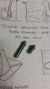
It was getting towards the end of the evening and I had a fair amount of noise to make, so I got to work setting some standard grade 1/4-28 bolts into a drill and then using the drill on the grinder to make some “whack-a-bolts”!  These little babies are threaded into the inboard and outboard wheel pant mounts, then when the time is right… BAM! You whack from the outside of the wheel pant and it makes a nice mark and/or indent (depending on how hard you whack it!) so you know right where your mounting screw hole needs to be drilled.

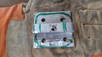
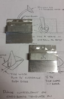
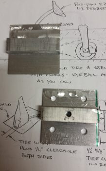
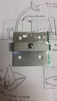
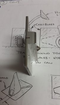
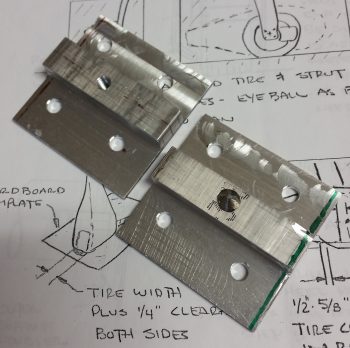
Here are my inboard mounting brackets that I made up a long time ago, using tried and true Neanderthal machining methods! . . . ha!  They need some TLC in the surface smoothing department, but I’ll wait until I have them cut to the specific size and shape for each wheel before I make them look all nice.

I then transferred the bolt hole pattern of the 4 right axle bolts and drilled those out on the right-side inboard wheel pant mounting bracket.  I then drilled and tapped a 1/4-28 hole in the center for the inboard wheel pant mounting screw.

I then threaded in the shorter of the two “whack-a-bolts” into the right wheel pant inboard mounting bracket.

I then transferred the bolt pattern and drilled the four 1/4″ axle bolt mounting holes into the left side wheel pant inboard mounting bracket.  I then drilled and tapped the center 1/4-28 inboard mounting screw hole, just as I did on the right side mounting bracket.

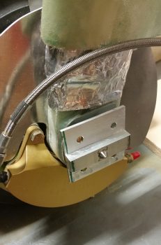
So you get an idea of just what I’m on about with these wheel pant inboard mounting brackets, I mocked them up quickly (just set over top of the axle bolts) to grab some pics of them “in action.”

The one on the right wheel still has the “whack-a-bolt” in it, and the one on the left side has a 1/4-28 mounting screw threaded into it.  Again, I’ll do a lot of cutting, shaping and cleaning on these inboard mounting brackets before their final installs.

Tomorrow will be Day 3 of the 3-DAY BLITZ.  I’m fairly confident I can get these wheel pants pretty much installed.  There may still be a few minor tasks left to do after tomorrow, but the overwhelming lion’s share of the install should definitely be finished!


Chapter 23 – Firewall Final Cleanup

I started out today researching and reacquainting myself with the wheel pant install tasks that I had undertaken about 2 years ago.  I then wrote out my wheel pants install task list.

When I went down to the shop to do some major rearranging before jumping into the start of the Wheel Pants 3-DAY BLITZ, I realized that there was quite a bit I had not yet finished on the firewall.

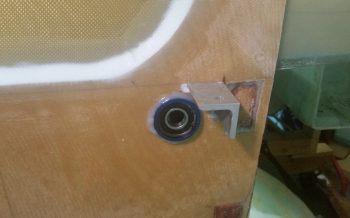
First off, I pulled the protective tape off the components of the CS123 control bearing floxed in place on the firewall.

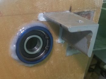
Here’s a closeup of CS123 floxed into the firewall.  I realize (yes, after looking at my notes!) that there was a reason I was waiting to do this, and that the plans have you install the actual firewall Fiberfrax and metal sheet in Chapter 15.  Well, I was in Chapter 16 . . . oh, well.  There’s definitely a 6 and 1/2-dozen thing going on here because I really wasn’t ever keen on floxing this thing to a metal covered firewall.  So I’ll deal with the minor inconvenience of mounting the Fiberfrax and firewall sheeting over top and around my floxed-in CS123 bearing.

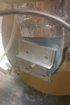
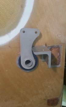
Here’s another shot with the aileron control tab slid into place. A couple things on the elevator control tab . . . if it looks closer than it should to the lower right engine extrusion, it is.  First off, that’s because the engine extrusion is 1.25″ wide vs. the plans’ 1″ wide.  Thus we’re clearly missing 1/4″ clearance that would normally be there.  That clearance will be attained from both sides giving a little: 1/8″ to be exact.  If you look at the extrusion, the majority of a 1/8″ trim on the edge would be primarily in the tapered edge area of the angled piece of aluminum.  On the aileron control it will just be a rounded little notch that is carefully made in the tab.

I then cleaned up the lower firewall by hacking off the lower longeron nubs that were sticking out of the firewall.

And then sanded them down so they looked like this:

I then sanded the edges of the interior Hell Hole BID tape layups, and worked on the bottom longeron to firewall corners a fair bit.  As you can see, the SD-8 Alternator relay and aileron control tube are looking ok.

I then did a quick test install of the engine mount on the firewall to ensure my efforts were all for a good cause!  Actually, the quick test fit came after a half hour of me chamfering all the engine mount bolt holes on the firewall extrusions, then taking a file to the engine mount to clean up the rough edges on the bolt holes.

The engine mount fit well, although I noticed that the lower right engine mount stub was gapped vertically with the lower right extrusion about 0.030″, and the left the same at about 0.020″.  I think there’s enough flex in all this that they can be cinched up fine without any undo stress, but it is interesting how these things appear after the fact.

Here’s a shot of the left and right side test-fitted engine mount.

Early evening I was finally able to initiate operation 3-DAY BLITZ on the wheel pants.  I got the wheel pants out and put the halves together on wheel pant #2.

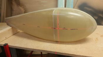
I then rechecked the alignment using a laser crosshair on wheel pant #1.

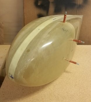
After I got all the axes aligned, I then taped up wheel pant #1 to secure the sides from moving (the sides are so tight fitting that they aren’t going anywhere anyway).  After spending a good bit of time finalizing where I wanted the screw mounting holes situated, I drilled some 1/8″ holes where the screws/CAMLOCs will go and then Clecoed the holes.

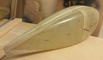
Here’s a shot of the aft side of the left wheel pant.

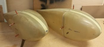
I then aligned, drilled and Clecoed the second (aircraft right side) wheel pant and then snapped these shots:

I then drilled a small hole in the CL front and aft of the wheel pants and placed 16 penny nails in the holes.  To ensure the nails stay aligned, I hit them with some hot glue.

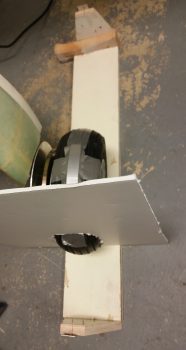
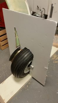
I then finished making the mounting jigs for the wheel pants.  For the jigs I’m going with the Wayne Hicks’ style and have screwed-on adjustable elevation tabs both fore and aft on each installation jig.

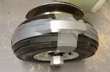
After ensuring the main gear tires were full of air (70 PSI) I then taped up a 3/8″ foam piece on the top of each of the wheels to serve as a spacer to keep the wheel pant from rubbing on the tire after the pants are installed!

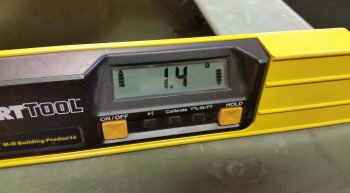
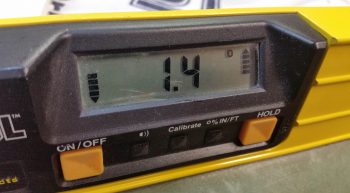
I also set the fuselage at a 1.4° nose up angle as you can tell by the right longeron (left)  and the left longeron (right).

Tomorrow I will continue forward with my 3-DAY WHEEL PANTS BLITZ!


Chapter 16 – Control System Bearing

Since I’ve been hitting the shop hard for the last few days, today was a light on shop work, heavy on research day.  I identified over 90% of my required components to roll my own fire-sleeved engine hoses (thanks Joe Coraggio for the tip on your website!).  In fact, I pulled the trigger on the first of 3 major orders that I’ll be placing for the engine hoses.

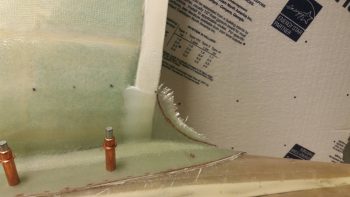
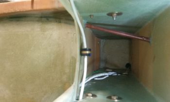
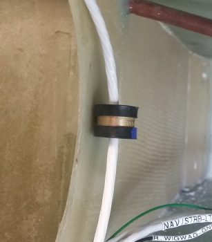
I then checked my interior CS Spar Clickbond installation that will serve as a hardpoint for the cable management Adel clamp.  Now, I don’t mean to brag, but clearly as decent as this layup turned out (90% of it in the blind), I need to start doing these things with my eyes closed!!! Ha!

Here’s a wider angle shot that provides a general idea of the entry and exit points for the wires in the cable bundle.

And one last closeup of the mounted Adel clamp.

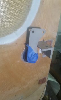
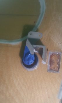
I then did a bunch more research, but wanted to get something curing overnight.  I had already planned on installing the CS123 control system bearing into the firewall tonight…. so, that’s what I did.  I lined up the aft end control rod with the one that runs along the fuselage sidewall, mixed up some rather wet flox, and then floxed in the CS123 bearing (this is a Cozy Girrrls product btw).

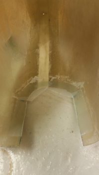
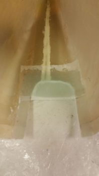
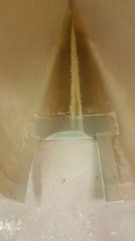
Here’s a slightly lower angle shot.  I also got up into the hell hole and added a flox fillet around the front side as well.  I don’t this thing will be going anywhere with as much flox that’s holding it into place!

Tomorrow I have just a quick couple of sideline tasks to complete and then I’ll move right into my 3-DAY BLITZ on the wheel pants!