Chapter 22 – Electric Push

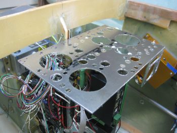
I started off today with the intent to finish the edging on the lightening holes on the Triparagon cross shelf.  But that didn’t happen.

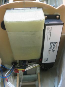
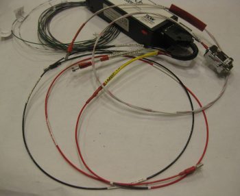
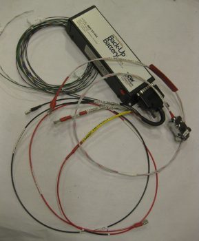
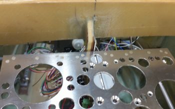
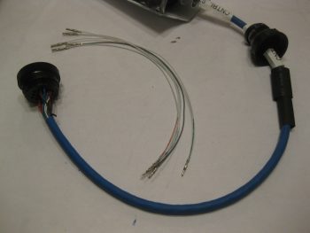
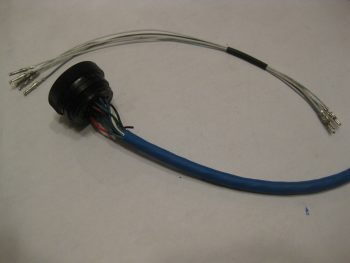
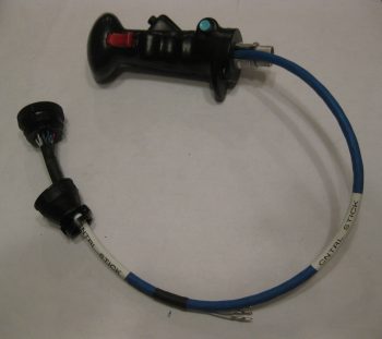
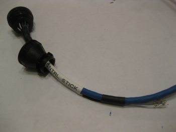
What did happen was I did a test fit of the IBBS & it’s ‘new & improved’ wiring harness.  Part of that test fit was to ensure that ALL the wires –not just the IBBS wires– fit through the hole & protective grommet that traverses the Napster bulkhead.  And, as per usual, since I just happened to be in the neighbor hood, I figured I couldn’t really test if the wires fit unless the actual wires (and cables) that will run through this transit hole are used in the test.

So I decided to go ahead and get the landing landing light and taxi light wiring/cabling knocked out.

First up was the landing light.  The installation manual for the AeroLEDs Sunray Plus landing light calls for using 20 AWG shielded wiring to power the light.  I only had 22 AWG on hand, so I used it since I’m confident that it will work since the actual run is only about 5 ft vs 3-5 longer than that if it was buried out at the end of a wing somewhere in a “typical” install.

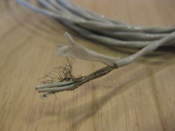
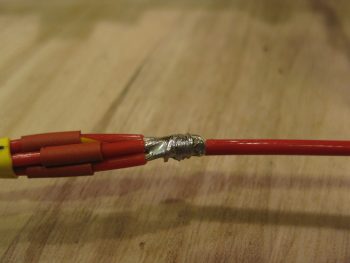
I started by stripping away about 2″ of the outer jacket.

2-wire 22AWG shielded landing light cable

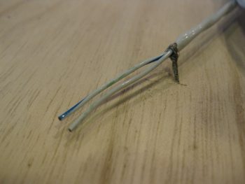
I then wrangled and cut the shielding wire.

Wrangling shielding on landing light cable

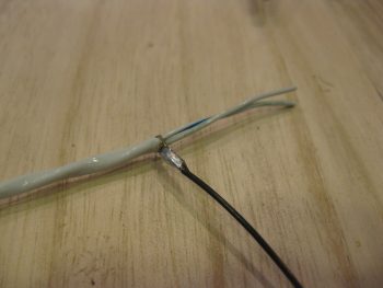
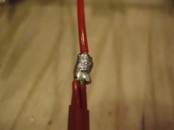
And soldered a piece of 22AWG black wire for the ground wire.

Ground wire soldered to shielding on landing light cable

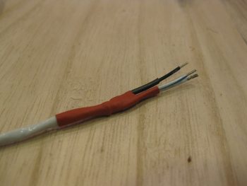
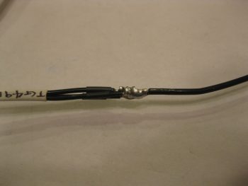
I then heat shrinked it all up: red to symbolize positive power, and black for the negative ground wire.

Landing light cable end reinforced with heat shrink

I then terminated the wire ends with mini-Molex socket connectors.  Note that the black pigtail wire will actually terminated on a mini ground tabs block that I’ll have mounted onto the negative post of the battery.  [Note: Although I’m not a fan of Molex connectors for the larger, multi-pinned connectors, the mini-Molex connectors work just fine for 2-6 wire applications … just my opinion, YMMV].

Landing light cable min-Molex sockets & ground pigtail

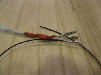
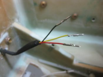
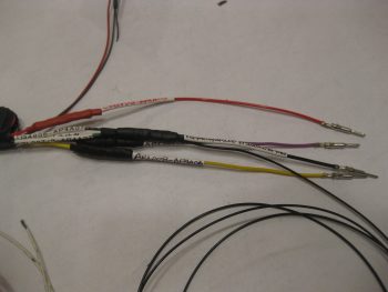
I then prepped the landing light side.  I had 2 extra wires that I simply folded back onto the main cable and heat shrinked in place.  I then terminated the remaining 3 active wires (red for light power, black for ground, yellow for wig-wag) with mini-Molex pin connectors.

Fuzzy land light wires prepped & pins crimped on

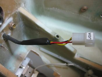
And then attached the 4-pin mini-Molex connector (J0, A side).

mini-Molex connector (J0A) housing in place

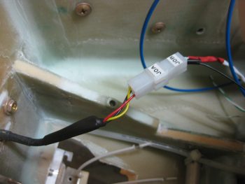
After running the landing light cable through the hole & grommet in Napster, I then connected the J0B side of the landing light connector to the J0A side.  Looking good!  Note in the pic above and below the white wire leads of the taxi light, those will change in a bit.

Landing light cable connected to landing light

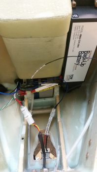
I had previously installed the IBBS to test its fit.  As a side note, after some investigation I realized that the end of the IBBS box cover (that has the “IB” label attached) was bowed out a bit & thus not allowing me to use normal sized AN3 nuts.  So I removed the IBBS cover, gently pressed the end back straight, reattached it and . . . Voila!  It mounts perfectly!

Back to the wiring… Get this: to get all the wires to fit, I actually have to removed the grommet out of the lower wire transit hole in Napster, then push the 2 knife splices through, then the PIDG FastOn connectors for the IBSS power & ground wires, then reinsert the grommet before the rest of the wires can go through.  Also, I can’t terminate OR LABEL any more wires at this time if they are going to fit through that hole…. VERY TIGHT FIT! Which is good because of course it keeps the wires secure.  It also gave me a chance to try out my “Wire Spoon” that I picked up from Stein a million years ago and have never used.  Works great and really does allow you to insert wires through the hole in the midst of a big wire bundle that you would otherwise not be able to get in there.

IBBS test install & wire run to ensure fit/clearances

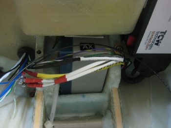
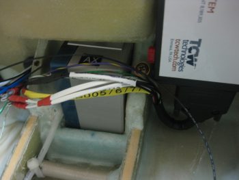
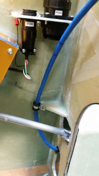
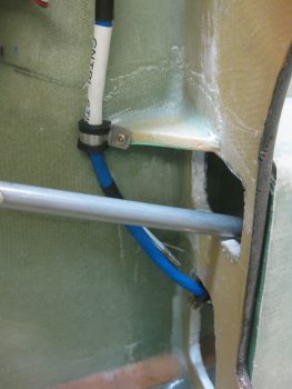
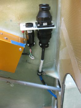
The next couple of shots are simply closeups of the IBBS wiring harness crossing over the nose gear back up battery, just underneath the nose tool box, and exiting out of the nose through the lower hole in Napster.  (You get a better shot of the IBBS harness “U-Turn” in pic #2).

IBBS wiring harness in & test fit wires thru BH

IBBS test install & wire run to ensure fit/clearances

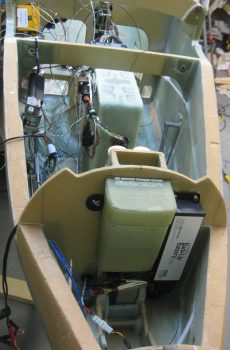
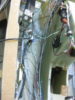
Here’s a long view of “Electron Alley” showing the myriad of wires that are currently in play and that I’m contending with.

"Electron Alley" - lots of wires!

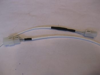
I then set to work to terminate and wire up the Taxi Light with a 22 AWG blue wire for power (blue just happens to be the color of the wires used in the Infinity stick grip for that switch, so I carried that color all the way through) and a 22 AWG black wire for ground.  Note that I also labeled the wires on the light side, something I didn’t have space to do on the landing light.  I finished off the installation using a 2-pin mini-Molex connector (J7) that I bought well over a year ago specifically for the taxi light connection.

Taxi Light connector & wiring

Here’s a closer shot of ‘Electron Alley’ . . .

"Electron Alley" - lots of wires!

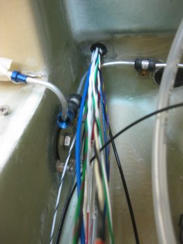
And a shot of the lower wire transit hole in Napster from the aft side.  The wires you see are currently all the wires that I plan on having transit through this hole (yes, things can change, thus the emphasis on the word “currently”!).

Aft side Napster BH wires thru hole and grommet

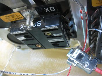
I also wanted to get a pic of the old ATC fuse block X-Bus (left) compared to the new 9-Pin  D-Sub X-Bus (right).  As I pointed out before, this modification will save space, weight and complexity (e.g. no individual fuses).

Old vs New X-Bus

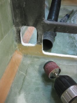
I was heading out to dinner with a buddy of mine, but before I ran out I wanted to get one more thing finished for the evening: widen the lower left hole in the instrument panel bulkhead to allow the P4 connector, which was just a tad too big (note the black markings on the sides of the hole) to fit.  I used a sanding drum on my drilled, fired up my shop vac and went to work.

Widening lower left hole in IP BH for P4 clearance

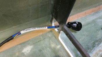
Less than a minute later . . . Voila!  Now the P4 connector just fits through the hole!  My next step will be to add an Adel clamp to keep the throttle handle cable secure.  I would like to reiterate my ongoing theme here by pointing out that this is the type of stuff I really want to get figured out before I close up the nose, while I have infinitely much more access to work on it all.

P4 connector access thru IP bulkhead

Tomorrow I’ll continue on with my push to knock out the avionics area electrical stuff, as well as get the Triparagon install finished. (Then, on to the wheel pants!)


Chapter 22 – Landing Brake Wiring

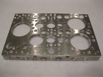
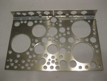
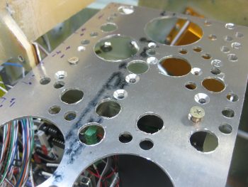
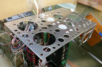
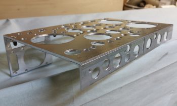
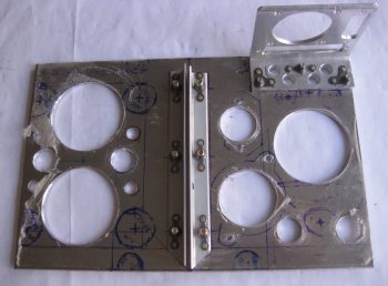
Today I started out by finishing up the lightening holes on the Triparagon cross shelf.  I drilled small 3/8″ holes in literally every spot that there was space to, again to get this thing as light as possible without compromising strength.  I removed the PQD bracket to drill lightening holes on the cross shelf above where the bracket mounts.

Triparagon cross shelf - Top

After drilling the last of the lightening holes, I then spent a good hour and a half deburring the holes and cleaning up the cross shelf.  I still need to finalize the deburring, but I at least got the rough stuff off the hole edges.

Triparagon cross shelf - Bottom

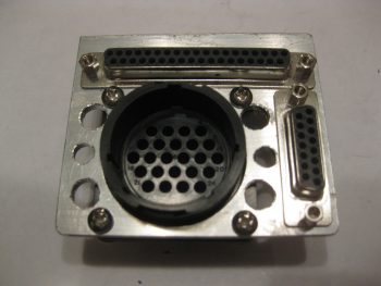
I also drilled lightening holes in the PQD bracket, which again I need to finalizing the deburring on those holes as well.  I then mounted the P6, J3 and J4 connectors.

PQD connectors & Bracket

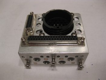
Here’s another view from the top.

PQD connectors & Bracket

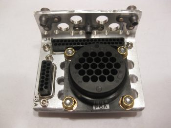
And an aft bracket view (technically a forward view).

PQD connectors & Bracket

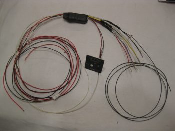
I then spent a couple of hours prepping my Jack Wilhelmson Landing Brake wiring harness.  Below you can see the included switch panel for mounting the switch and LED lights to the instrument panel.  I removed that switch since I replaced it with the switch in the throttle handle to control the Landing Brake, which means that the wiring goes through the P4 connector.

The majority of time I spent working on this bad boy wasn’t the actual physical wiring stuff, but in tracking down, confirming & verifying what wires went where to label them correctly.  Again, since I’m utilizing connectors now in my electrical system wiring scheme, much of my previous A → B wiring is now A → ⊗ | ⊗ → B where ⊗ is the connector.  Since many of my wire labels are now outdated, I simply crossed out the old label with a Sharpie and rewrote the new labels by hand to use up my stock of “bad” labels on this wiring harness.

Landing Brake wiring harness

Since the wires coming out of the relay decks were too short to comfortably terminate into the P4 connector, I had to extend these wires.  Instead of soldering them, I went the lazy route this time around and simply used butt connectors.  I then used heat shrink over the crimped butt connectors.  As you can see, I finished labeling all these harness wires, and then crimped AMP CPC pins on the ends of the 4 Landing Brake wires that will get terminated into the P4 connector.

Landing Brake harness wires AMP CPC pins

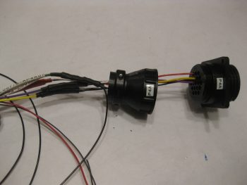
Here are the 4 Landing Brake wires terminated into the P4 connector.  Note that I slipped the cable clamp into place before terminating the wires.

Landing Brake harness wires in P4 connector

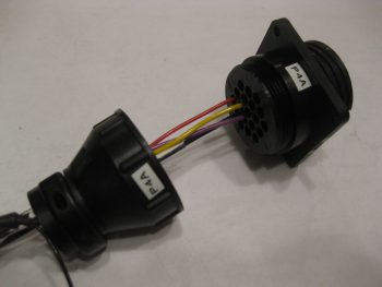
A closer shot of the Landing Brake wires in the P4 connector (A side).

Landing Brake harness wires in P4 connector

Tomorrow I’ll press forward on the Triparagon and the avionics bay wiring.


Chapter 22 – IBBS Wiring & New X-Bus

I started off today by updating and printing out my connector pinout sheets for the following connectors:

  • P4 – Throttle Handle AMP CPC
  • P5 – Infinity Control Stick AMP CPC
  • P6 – Panel Quick Disconnect (PQD) AMP CPC
  • X-Bus – IBBS-Powered Avionics Bus 9-Pin D-Sub
  • J3 – PQD Panel Power Connections 15-Pin D-Sub
  • J4 – PQD Panel Signal Connections 37-Pin D-Sub

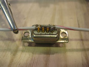
At the tail end of my updates my buddy Marco called.  We talked a bit on EZ stuff, and as we spoke I got to work on soldering two 16 AWG wires to the back of a 9-Pin D-Sub connector (that I repurposed from its original role as the TruTrak ADI wiring harness).

This 9-Pin D-Sub will become the new X-Bus, replacing the original 8-slot ATC fuse holder that was the X-Bus.  As per one of my very educational discussions with Bob from TCW Technologies on the IBBS install, he informed me that I don’t need to power a fuse panel since all the components powered by the IBBS must not max out past 5 amps, and the integral 10-amp mini-ATC fuse on the side of the IBBS protects these items.  I had already chucked a panel-mounted switch that manually switched IBBS power to E-Bus power (EZ’er to let the IBBS to perform this standard function), and now I was eliminating more weight and complexity by swapping out the ATC fuse panel  X-Bus for the new & improved 9-Pin D-Sub connector X-bus.

Now, I did originally plan on using two 18 AWG wires, but Bob advised to use 16 AWG wires.  They still seem like a bit of overkill to me, so I have to admit I went 16 AWG on the other 2 wires (power & ground) that Bob intoned should be 14 AWG.

Building the new X-Bus from a 9-Pin D-Sub

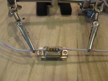
Here’s a closer shot of the two 16 AWG wires to be soldered onto the back of the 9-Pin D-Sub connector that will replace the current X-Bus.

Building the new X-Bus with two 16ga wires

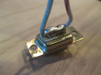
I then soldered the 16 AWG wires into place.

New X-Bus 16 ga wires soldered onto 9-Pin D-Sub

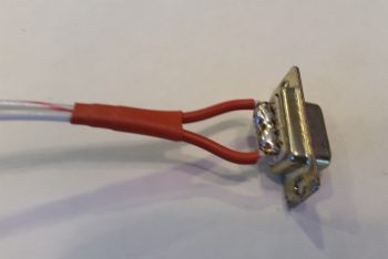
And prepped them with heat shrink . . .

New X-Bus Connector & Cable

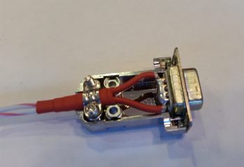
Prior to mounting the wires/connector assembly in a D-Sub backshell.

X-Bus D-Sub connector backshell

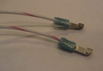
Since I want the IBBS-to-XBus circuit to have a break in it –since the wires pass through the Napster bulkhead– to allow the wires to be run without concern of the D-Sub connector getting in the way, or if unable to traverse bulkheads, I terminated the ends of the two 16 AWG X-Bus feed wires with knife splice terminals.

Forward end of X-Bus cable: 2 knife splices

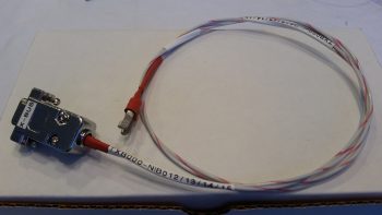
Here’s a shot of the finished X-Bus cable (A side, from IBBS).

Completed X-Bus to IBBS cable

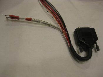
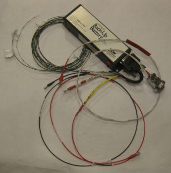
I then traced out, toned out and cut off about 9 feet of wire to trim down the four 20 AWG X-Bus feed wires coming out of the IBBS.  I toned them out to ensure I had the correct wires, then terminated them into pairs, into 1 knife splice each.  Thus, what I have is 4 wires exiting the IBBS unit, then those getting terminated into pairs with knife splices, then each pair connecting to a 16 AWG wire that feeds the X-Bus 9-Pin D-Sub connector (actually, the way I soldered all the pins together, it’s technically a 9-Pin D-Sub Buss).

IBBS side of X-Bus leads: 2 knife splices

I then turned my sights on the 3 pass-thru power wires and 1 main bus voltage sensor wire.  In my discussion with Bob, he said it was perfectly ok to run these all together and fuse it with 10 amps off the main bus.  So that’s exactly what I did! [Conversely, the IBBS install manual shows one fused feed to the main bus for the 3 pass-thru wires, and another fused feed for the sensor wire… always good to talk straight to the guy who designs this stuff!]

Since the other end of these 4 wires converged into one is simply a FastOn PIDG connector, I didn’t create a break in this wire group.  I merely bundle them all together and slathered with hot solder!

IBBS 3 pwr & 1 sensor wire into a 16 ga wire

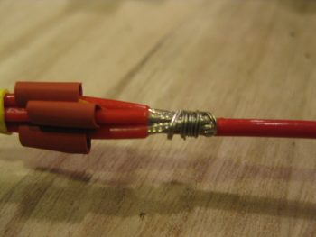
As you can see, I did the Bob Nuckolls’ technique of making a 2-wire pigtail from the 16 AWG wire, then wrapping that around the bundle of wires so that they are all nice and tightly snug before soldering.

Soldering 4 IBBS wire leads into one 16ga wire

Here’s my IBBS 3 pass-thru power wires and bus volt sensor wire soldered to the !6 AWG wire on its way to the main bus.

4 IBBS wire leads soldered into one 16ga wire

I then did the same thing for the 3 ground wires that get grounded on the panel ground block (G4).

3 IBBS GND leads soldered into one 16ga wire

You may have noticed that some of my wire labels are hand written.  There are 2 reasons for this: First, I ran out of the correct size wire label heat shrink (I’m waiting for an order to arrive), and second, I’m reclaiming some printed labels that fell victim to becoming obsolete when the new world order of PQD came into existence.  I prefer to be more practical than flashy, so to save money I simply lined through the old printed label on the heat shrink piece, flipped it over and ever-so-nicely printed a new, correct label on the other side.

In hindsight, I should have taken a pic of the entire IBBS wiring harness before I started this process to contrast with what you see below, which is just a few random pics of the completed IBBS wiring harness.

IBBS & X-Bus wiring

I have 3 wires out of the original 14 that did not get cut or combined:

  • IBBS Master Switch (to panel switch)
  • Info lead (to GRT HXr EFIS…via J4)
  • IBBS Low Voltage Warning (to AG6 Warning Annunciator)

And the wires that did get cut & combined:

  • 4 X-Bus Power leads into 2x 16AWG wires
  • 3 Pass-thru Power wires & 1 Bus Volt Sensing wire into 1x 16AWG wire
  • 3 Ground wires into 1x 16AWG wire

Among other things, this simply means that I now have half the wires to keep track of (7 vs 14) coming off the IBBS wiring harness, and fewer wires passing through the Napster bulkhead.

IBBS & X-Bus wiring

One final point of note.  Due to how the IBBS box is mount vertically on the front left face of Napster, as the wires in the harness exit the IBBS D-Sub connector they must immediately make a U-Turn to get keep from dragging on the floor of the nose battery compartment.  One of my first tasks tonight was to place a large piece of black heat shrink over all the wires in the harness.  Then before applying heat, I zip-tied the harness back onto itself in a “U” shape.  I then heat up & shrank the tubing and it kept its “U” shape perfectly.  Pretty cool!

IBBS & X-Bus wiring

Tomorrow I’ll continue to work on both the Triparagon & the wiring in/about the avionics bay.


Chapter 22 – Triparagon Cross Shelf

Technically, I started off today by spending about 2 hours finishing up my blog & tweaking this website.

I then called Bob at TCW Technologies and had a good discussion on connecting the IBBS power cables to the 9-pin D-Sub connector that will be the new X-Bus (vs the ATC fuse panel).

I then went down to the shop, marked up the front top edge of the Triparagon cross shelf in the location where I would drill the beginning holes for the rivets that will secure the parts mounting overhang tabs.

Triparagon cross shelf marked for front overhangs

My first real action though was drilling the front & aft rivet holes on the mounting flanges that secures the cross shelf to the vertical plate.  These are the first 2 of 4 total larger diameter rivets that I’ll use to secure connect these Triparagon pieces.  I couldn’t actually press the rivets in place since I can’t get in there with my rivet pressing tool, so I’ll have to mount the rivets when I remove the vertical Triparagon plate.

Riveting cross shelf to vertical plate

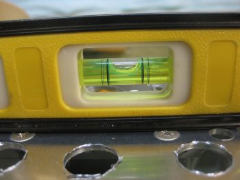
I drilled the aft rivet hole first (right, above) since the cross shelf needed to come up about 0.070″ on the front side to be at 0° level, which is what the double-checked longerons showed.  After drilling the front side & inserting the rivet, I confirmed that the cross shelf was still level from front to back, matching the 0° longeron level… which you can see it did!

Cross shelf matches 0 degree longerons

I took this shot specifically to show the 6 countersunk screw positions that are used to hold the cross shelf to the vertical plate via the angled mount extrusions and nutplates. You may note in the next pic that the nice aluminum material in the areas between the pairs of countersink holes were targeted for lightening… Yes, the weight loss program continues!

Removing cross shelf plate

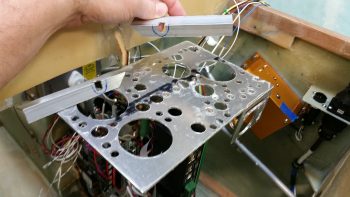
In the pic above you can see all the dots along the leading edge of the top cross shelf where I marked the it for the rivet drill points.  I then drilled a 1/16″ pilot hole at each dot where I would be installing a rivet.  I then I clamped each overhang piece in place, drilled the #40 hole through the cross shelf pilot holes into the overhang extrusion clamped underneath.  I then deburred all the rivet holes, and then mounted one overhang at a time.  I would drill the countersink on a rivet hole, press the rivet into place and then move onto the next rivet.  You can see all the rivets installed below, which of course means that the overhangs are mounted.  Also note there are a number of new lightening holes.  After I drilled the new lightening holes, I spent a good 20 minutes cleaning up the rough edges of the larger cross shelf lightening holes.

New lightening holes & rivets!

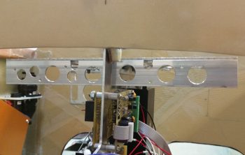
The overhangs have the dual purpose of providing a mounting surface for the CrackerJack parts, and also to provide a flange to mount the upcoming diagonal supports that will secure the outboard ends of the cross shelf to the upper mid-point area of the vertical plate.  You can see that I pre-identified the locations for the airspeed switches and drilled the mounting holes on the overhangs before riveting them in place.

Cross shelf front overhangs - action shot

Here’s a shot of the overhang rivets . . .

Cross shelf overhangs rivets

And a shot of the entire Triparagon cross shelf . . . in repose!  ha!  I weighed the cross shelf with its attached brackets, and with the new lightening holes it weighs in at 0.476 lbs. Add that to 0.7 lbs of the vertical upright (which will get another round of lightening holes) and I get a respectable 1.176 lbs total currently.  Again, I suspect that I’ll come in at about 1.1 lbs for final Triparagon install weight.

Cross shelf front overhangs

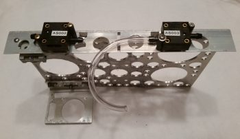
I then mocked up and test mounted my Crackerjack parts, aka airspeed switches, onto the front overhang mounting tabs.  Note that airspeed #1 is mounted on the right side (left in the pic) on the aft side of the overhang tab staggered behind and just to the left (looking from front) of airspeed switch #2.  I mounted airspeed #1 to allow me to adjust the target airspeed set point with the setscrew.

Airspeed switches test mounted

I then spent a good couple of hours updating my IBBS wiring diagram and determining the pinouts for my PQD (Panel Quick Disconnect) connectors.

Tomorrow I’ll continue working on the Triparagon and the avionics bay electrical wiring stuff.  I figure I have at least another good week to finalize this round of electrical system stuff before moving on to the wheel pants!


Chapter 22 – Throttle Handle Wired!

As I was finalizing my last blog post the doorbell rang. It was my mailman delivering my order from Stein, so after I finished up my blog post I opened up the box to check out all the goodies.  I took the 6-pin mini-Molex and quickly mounted the B-side to the roll trim cable. I already had labels made up so I quickly labeled both sides of the J5 jack as well. (As a reminder, my labeling scheme for connectors is quite simple: the “A” means it’s closer to the nose while “B” means tail side.  If the connector or jack is vertical, then the hard mounted side is “A” and the removal side is “B”).

Roll trim cable terminated into J5 connector

I then took a few minutes to prep the fuselage for me to sit in it and make some airplane noises.  I needed to figure out where my Dynon intercom box is going to call home, so I pulled the wood blocks out from under the nose wheel, cleaned the tools and extraneous components out of the front seat and climbed in.  I discovered that I can reach back and manipulate the controls of the intercom if it’s against the right fuselage sidewall, just aft of the stick.  How about 2″ aft of the stick? … uh, nope, not really.  Too difficult there.  But half an inch back I can curl my hand down comfortably and work the intercom controls.

I like this position because it’s really unclaimed, unused real estate that can be put to good use.  Also, I’ve had my eye on the left armrest area just forward of the throttle quadrant to use for my environmental controls panel.  Now that I’ve decided to put the Dynon intercom on the right armrest console just aft of the stick I can reclaim the forward left armrest console for the environment controls!

In addition, in thinking about where my intercom control head would go, I naturally wondered where I was going to put my headset jacks.  I’ve discussed this with Marco in the past, and we had yet another quick exchange about it via text.  I really wanted to keep the headphone jacks off the panel, but where to put them?  After doing a bit of research last night, I would like to give a shout out to Nate Mullins –and in turn, James Redmon– for highlighting the very aft side of the armrest for being a good location.  Now, they picked the aft side of the left armrest to mount their jacks, but I’m leaning towards the right for 3 reasons:

  1. It keeps the headset wires on the right side of the seat when ingressing/egressing the aircraft.
  2. It keeps the electrical wires on the right side of the aircraft (power wires right, antenna cables left), and
  3. It keeps the shielded wire run betwixt intercom box and jack very short, and since  this specific wire run is the most susceptible to gremlins and things that go staticky in the night, I would rather keep it as short (aka noise free) as possible.

So that’s 2 fairly significant component placement decisions that I made today…. after literally years of those questions floating around in the recesses of my mind.

Ok, on to the task at hand: wiring the throttle handle.

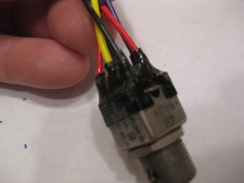
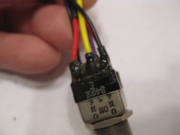
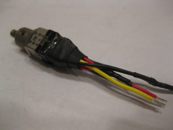
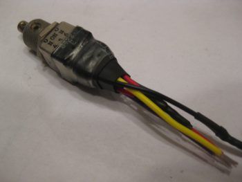
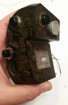
While down in the shop I collected up my throttle-handle-mounted nose gear switch that I had gooped up the aft end of with E6000 to secure the wires both to each other and to the switch body. Since these switches are older (but still look in great shape) and I had to wrangle off the massive amounts of old wiring, I want to make sure both the solder connections and switch connecting tabs stay secure, and are subjected to as little vibration as possible.

E6000 goop to strengthen wires

Here’s another shot of the E6000 gooped-up nose gear switch.

E6000 goop to strengthen wires

To finalize my wire-securing process on the nose gear switch, I added 2 pieces of heat shrink around the base of the wires and goop.

Double ply of heat shrink tubing

I then added a piece of heat shrink that secured the wire/goop subassembly to the body of the switch.

Heat shrink tubing to secure wires & terminals

I had to run down to my favorite hardware store to pick up a 2-56 stainless steel CS screw since I apparently lost one of the nose gear switch’s mounting screw somewhere.  I test fitted the screws, took it back apart and then judiciously used some E6000 on the screws and around the base of the switch mount before permanently remounting the nose gear switch into place on the throttle handle.

Nose gear switch mounted into throttle handle

Here’s how the developing rat’s nest of wires looked after I added the nose gear switch.

Nose gear switch in interior throttle handle

I should note that before I ran out to get the missing 2-56 screw (try finding one of those when you don’t know where it ran off to!) I gooped up the wires/switch intersection of the landing brake switch with E6000.  Here are a couple of slightly fuzzy pics to show you how it looked when it cured.

Fuzzy pic #1 of E6000 on landing brake switch

Fuzzy pic #2 of E6000 on landing brake switch

I then repeated the heat shrink process on the wire/goop area of the landing brake switch.

Heat shrink tubing on landing brake switch

Then secured it to the switch body with a clear piece of heat shrink.

Final clear heat shrink on landing brake switch

I then installed the bottom and last switch for the landing brake into the throttle handle.

At this point it was time to start connecting all the throttle handle switches’ wire leads to the blue cable.  I spent a good 3 hours soldering all the switch lead wires to the blue cable harness wires.  I had already identified which wires in the blue cable were 22 AWG and which ones were 20 AWG, and had to account for this when wiring up the switches.  I did only 2-3 wires at a time, ensured they toned out, then added heat shrink (that I had to ensure was on the wires before I started soldering) over the solder joint before moving onto the next few wires.

Throttle handle Landing Brake switch installed

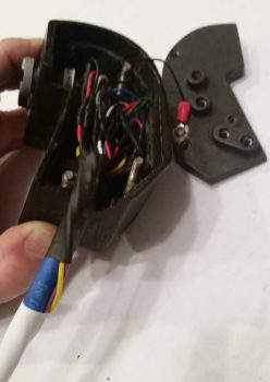
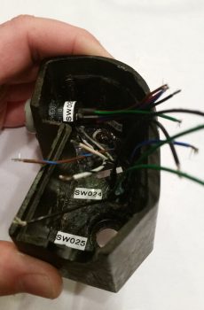
Then it was time to start cramming… wires that is.  There was actually enough room in the throttle handle housing to stuff all the wires back into it comfortably.  As you can see I reclaimed one of the ring connectors from the original harness and pigtailed it off the ground wire for ground to the throttle handle housing.  You can also see that in this and subsequent pics that I finalized securing the two extra 18 AWG wires spiraled about the blue cable.  I also labeled the cable and added lengths of heat shrink to secure the two 18 AWG wires.

Stuffing wires back into the throttle handle!

I then remounted the throttle handle side plate cover with the 3 original screws.

Throttle handle side cover reinstalled

Here’s a shot of the throttle handle with all the switches rewired & remounted and the cable prepped for having an AMP CPC connector terminated onto it.

Throttle handle cable completed

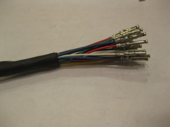
I then terminated all the wires with AMP CPC connector sockets.

AMP CPC sockets terminated on throttle handle cable

Since I had NOT actually created the pinout scheme for the P4 connector, I stopped work and spent a good 45 minutes determining the pinouts for this connector.  Once done, I toned out the wires to ensure both continuity and to check wire IDs since there were multiple wires for each color (e.g. lots of red & black wires).  As I determined what wire was what I then placed them into their appropriate numbered socket hole.

Sockets inserted into P4 AMP CPC connector

Here’s a closer shot of the throttle handle switch wiring terminated into the AMP CPC connector housing.

Sockets inserted into P4 AMP CPC connector

And here’s a shot of the front face of the P4 (B-side) AMP CPC connector.

Sockets inserted into P4 AMP CPC connector

I then secured the wires with silicon rubber self-sealing tape before finalizing the cable clamp install.

Final wire wrap on P4 connector before cable clamp

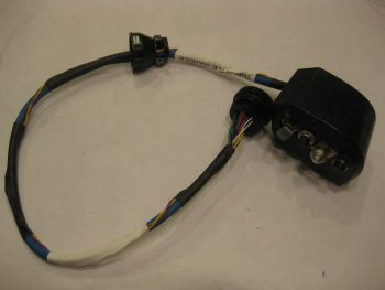
I then mounted the cable clamp to finish the throttle handle cable.

Throttle handle cable assembly completeThrottle handle cable assembly complete

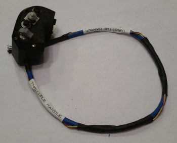
Here’s a shot of the full length throttle handle cable.

Throttle handle cable assembly complete

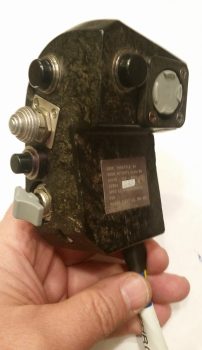
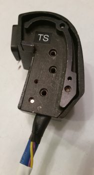
And a final shot of the throttle handle and P4 connector.

Throttle handle cable assembly complete

Tomorrow I’ll be back working in the avionics bay, both on getting Adel clamp hard points installed and finishing up the Triparagon.


Chapter 22 – Wiring Throttle Handle

This post covers today and yesterday since I was remiss in posting yesterday.  This weekend has been a busy one both socially and of course with football (yes, I’m an avowed football junky!).

Ya’ll have probably noticed that as I work on any one component, I like to knock out those components directly around it since I’m already “in the groove,” plus it gets those items finished.  In addition, I already know how they fit into the area that I’m working. I understand that my build methodology is somewhat organic, and often unscripted, but staying motivated and simply getting many productive hours in on the build a day is the key to having an airplane sitting on the ramp vs a project in your garage, right?!

And so it is with my electrical system.  There are a myriad of low hanging fruits right now that I’m simply going to knock out: changing as many variables into constants and resolving as many unknowns as I can at this point in the build.

Thus, it is that one of those low hanging fruits right now is the throttle handle.  As I’ve stated before, especially in an airplane as space constrained as a Long-EZ, I am a total believer in maximizing the HOTAS (Hands on Throttle and Stick) concept as much as possible.  If it’s good enough for task-saturated military fighter pilots, it should work fairly well for us too.

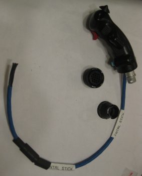
I started off yesterday by determining my wiring gage requirements for the throttle switches.  I then assessed the 17 wires in the 2+ ft of leftover blue cable that I cut off the Infinity stick grip.  After listing out all the wires and gages, I determined that I could I repurpose this leftover blue cable for the throttle handle switches.  Since there’s only 17 wires in the cable, I’ll also run two 18 AWG wires for the landing brake along the outside of the blue cable, for a total of 19 wires to the P4 AMP CPC connector.

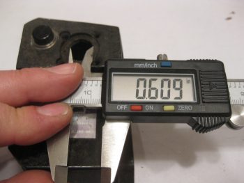
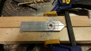
I then got to work widening the mounting hole diameter for my 5-way castle switch (“joystick”) that controls a few A → B options on the GPS (i.e. GPS to VLOC) or page/screen scrolling functions (Trio fuel screens, GRT screen flips, etc).

Current throttle joystick hole mount diameter

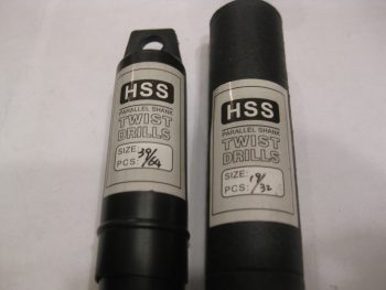
A few months ago I picked up these drill bits specifically for this task: the 39/64″ bit to drill out the majority of the hole diameter, then the 19/32″ bit to fine tune the hole size.

Drill bits for widening joystick switch hole diameter

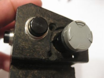
Here’s the hole post drilling, ready for the 5-position switch.

New throttle joystick switch hole mount diameter

The switch has a plastic keyway on the side for positioning.  Of course I could have removed it, but I decided to leave it in place and notch the side of the hole.  I clocked the switch position so that not only are the finger grips in the 3-6-9-12 O’clock positions, but also so that the ground connector tab was closest to the backside handle opening.

Throttle joystick switch keyway

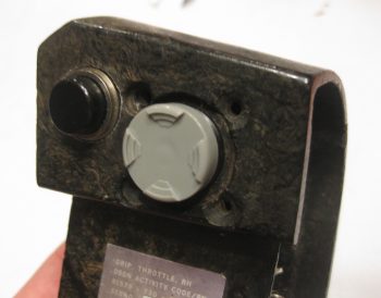
After notching the hole for the switch’s keyway, I then test fitted the switch.  So far I’m very happy with how this switch is working out!

Test fit of throttle joystick switch

Here’s an inside-handle shot of the 5-way switch, with the ground connector tab on the aft side of the switch closest to the handle opening.

Test fit of throttle joystick switch

Here’s a shot of the back side of the 5-position switch.  Note that the ground tab is the tab on the far left, away from the center 5 tabs..

Throttle joystick switch soldering tabs

I then cut, stripped & soldered the 5 switch position wires and the ground wire onto the tabs on the backside of the 5-position switch.

Throttle joystick switch wires soldered in place

Another shot of the wires soldered onto the 5-position switch.

Throttle joystick switch wires soldered in place

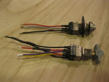
On the 2 other top mounted throttle push button switches… since I couldn’t get these switches out of the throttle handle without destroying or marring them greatly, I simply used the wires that were attached to the switches and soldered them to the identified wires in the leftover blue cable that I cut off the Infinity stick grip.

Well, after getting these 2 switches wires soldered to the blue cable wires, I then toned them out for continuity.  When I check continuity on my Fluke multimeter, I generally just check for sound and call it good.  But this time I actually caught sight of the resistance reading, which was on the order of 6 & 9 ohms for the respective switches. Whoa, pretty high resistance for basic momentary push button switches, what was going on?  Well, under closer inspection I realized that the heat shrink over the wires at the switches wasn’t just wires, there were resistors in line as as well.  Of course I don’t need resistors for these 2 switches, so they had to go.

After I removed the offending resistors, then the issue became soldering the switch leads onto the switch posts down in the very depths of the throttle handle housing.  Hmmm, I’m decent at soldering, but this proved to be a bit challenging.  I did it, but my confidence in the physical strength of the solder joints wasn’t as high to my liking, so I did what any responsible builder would do, I reinforced those solder joints by burying them in potting goop!  After testing the switches electrical continuity (good) and checking that the resistance was back down into the normal range (0.2Ω), I then used E6000 to cover up the freshly soldered switch lead wire joints.

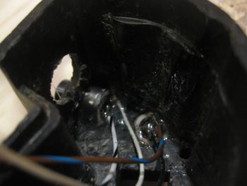
PTT and COM1 Freq FlipFlop switches potted

I went ahead and ran a strip of labels and printed off a few to label the switches on the inside of the throttle handle.

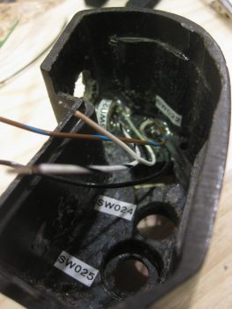
Throttle switches labeled

I then got to work on the SW024, the transponder Ident button & SmartStart arming switch.  I cleaned up the switch wire tabs and soldered the correct colored wires to the tabs.

Transponder Ident and SmartStart Arming switch

I then mounted the 5-position switch (SW020) and remounted the transponder Ident & SmartStart arming switch (SW024) into the throttle handle using RTV silicone, and set it aside to cure.

Interior throttle handle

As the 2 freshly added throttle handle switches cured, I then got to work on the nose gear UP & DOWN switch.  Again, I verified the correct size and colors of the wires, then soldered them into place.

Throttle mounted nose Gear switch wired

I then finished off the mojamma of the throttle handles switches, the landing brake switch with its multiple cross-pairs of wires.

Nose Gear and Landing Brake switches wired

Here’s a shot of the day’s tasks, with a total of 4 out of the 6 switches installed.

Throttle handle switches

Tomorrow I’ll install the last 2 switches and finalize the wiring on the throttle cable, to include termination the blue cable into the P4 AMP CPC connector (B side).


Chapter 22 – CrackerJack Parts Mount

Yup, today was a light build day!  Today I drilled a notch in each of the two 1″ parts mounting overhangs that will reside on the bottom front edge of the Triparagon cross shelf. Since I kept the shelf as small in dimensions as possible, space is tight all around.  Thus, the mounting screws at the 4 corners of the GRT GADAHRS box are located very near the cross shelf’s front and aft edge.  At the front side, the GADAHRS mounting screws on each side actually project through the cross shelf plate into the corners of the front parts mount overhangs, at the corner of the angled extrusions no less.

To create a notch to allow for the GADAHRS 2 front mounting screws, I simply clamped the parts mounting overhangs together and then used a larger 21/64″ drill bit to create the notch on each extrusion.  When I finished, the notch was deep enough on the vertical arm, but not the horizontal arm.  To remedy this I just remounted & reclamped them together with the horizontal extrusion arms positioned vertically together in the clamped assembly, then redrilled.  Voila! Good notches with space for the GADAHRS front mounting screws.

Cross shelf overhang AHRS screws clearance notchesI mixed up the order again slightly on my building task timeline due to my pics.  Before I drilled the notch in the parts mounting overhangs, I actually started out by going to town on Triparagon cross shelf and drilling a bunch of 5/8″ and 3/8″ lightening holes, as you can see below.  I feel like I should post a shot of the theater masks showing both funny & sad faces, because that’s exactly what this is… a bit of a lesson in futility it seems like! I drilled all those holes only to have the cross shelf weigh in at 0.53 lbs.  Thus, a total weight loss of only 0.04 pounds!  Wow!  I still have a few more spots where I’ll drill some holes, but I realized after this round of drilling lightening holes that my total target weight of 1 pound for the entire Triparagon assembly is probably not going to be met.  I will of course strive to make it as light as possible, but I think it will most likely have a final weigh-in of 1.2-1.3 lbs. Still much lighter than when I started out, considering the Triparagon vertical plate alone started out at just under 1.4 lbs!

Fiddling with shelf overhangs and shelf supports

I then spent a good 20 minutes measuring, assessing, checking, visualizing, test fitting, analyzing, mocking up & designing my final plan for the diagonal 1/2″ x 1/2″ angled aluminum supports that will be secured to the Triparagon vertical plate about 1/3 of the way down in line with the front edge of the Triparagon cross shelf.  The left & right diagonal supports will connect to the front edge of the cross shelf by being attached to the outer most edge of the parts mounting overhangs.

I will also have one diagonal support on the aft side that traverses from the inboard edge of the PQD bracket to the about midpoint on the aft edge of the Triparagon vertical plate. Clearly this is a total of 3 diagonal supports to keep the cross shelf secure specifically to provide a stable mounting surface for the GRT GADAHRS.  I suspect that once all the wiring bundles are in place and attached to the PQD connectors, and all the other bunch of wiring bundles around the Triparagon, that those will greatly assist in securing the cross shelf from any adverse movement as well.  If not, I’ll be prepared to run another cross shelf support from anywhere in the avionics bay to ensure the cross shelf is stable for the GADAHRS.

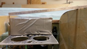
The last thing I did before taking off for the majority of the day/evening was to take my 1/2″ x 1/2″ angled support strut extrusion and use it to double check that the space gap between the top of the GADAHRS box (the tallest component on the cross shelf) and the nose structure between the instrument panel and F28 was good.  It’ll be a little tight after some foam & glass goes in there, but the spacing looks fine.

Rechecking GADAHRS to nose clearance

Later this evening, after I returned home, I took a large piece of paper and sketched out actual sized positioning for my switches and their panel positions.  With space so tight behind the panel (again, actually forward of the panel) I was specifically attempting to figure out where to put my Dynon intercom box.  It seems small, and it is fairly petite in height and width.  But add on the wiring harness D-Sub connector to the back side of this thing and now your talking over 6″ deep!  And that’s not even really accounting for the radius of the wiring bends that need to make a turn to go somewhere!  I came up with 3 spots that will actually, physically work and then assessed them on my panel sketch:

  1. Center top of the panel
  2. Left top console immediately forward of the throttle (my throttle quadrant will sit back some from the panel unlike the plan’s position)
  3. Right top console against the sidewall just aft of the stick opening (I did a full range of motion check with the stick and flight controls and there’s plenty of space since I had to kick the controls inboard 3/4″ to allow use of the Cozy Girrrls control parts)

I did pros & cons for all 3 positions, and quickly nixed the top center panel mounting idea. With an input jack for music, and the way the wiring would flow (read: get in the way) on the back side of the panel, this location just won’t work for me.

I will say that one issue I never really understood with Long-EZ’s until riding in my buddy Marco’s Long-EZ is that with the seat bulkheads designed/constructed the way they are, you cannot mount switches or items aft of where you can reach since your elbows cannot move aft at all…  since the physical seat back (aka “wall”) prevents it!  If you do, you have to mount the switch or device in a spot where you can reach over with the opposite hand to manipulate it.  This is exactly what I need to test out tomorrow, since I prefer the intercom face to be mounted on my right console just aft of the control stick/opening, tucked away against the fuselage sidewall.  But the question that needs to be answered is: CAN I REACH IT?!

Tomorrow will continue to be all things electrical for now.  I’m on a roll and I really want to knock out as much of this electrical stuff **pre-nose closing** while I can.  Just to reiterate, once I finish my current infatuation with the electrical system, I’ll be back building on the wheel pants!


Chapter 22 – Roll Trim Cable

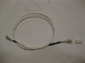
Today was kind of a light build day.  I did finalize and submit orders to SteinAir and ACS, but I also wanted to knock out the 5-wire roll trim & ELT GPS signal cable that piggybacks off the Infinity stick grip’s P5 connector.

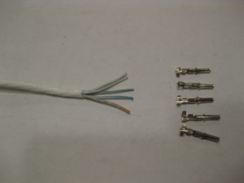
I started by trimming back the outer cable sheath and collected up my 5 mini-Molex sockets.  This first end that I terminated was for the P5 connector side since all these sockets will mount into a 6-pin mini-Molex connector housing (J5) that I just ordered from Stein.

5-wire roll trim & ELT GPS cable

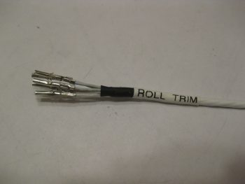
Here’s the mini-Molex connectors terminated on the P5/J5 connector side of the 5-wire roll trim & ELT GPS signal cable.  Although this cable does of course include the ELT GPS signal cable, I have given it the moniker –and label– of simply the “ROLL TRIM cable.”

Roll trim & ELT GPS cable mini-Molex sockets

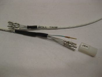
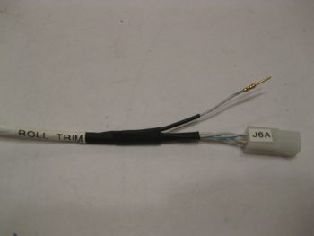
I then terminated the 5-individual wires on the roll trim servo end.  The J6 mini-Molex connector on that end is only a 4-pin connector, since that is all that is required to drive the Roll Trim’s RAC T2-10A servo.  I separated out the ELT GPS signal wire and terminated it with a D-Sub pin for future connection with the ELT GPS feed that will have a D-Sub socket.  I then terminated the other 4 wires with mini-Molex sockets.  I then added heat shrink to the wires groups.

5-wire roll trim & ELT GPS cable ends terminated

Here’s a closer shot at both ends of the Roll Trim Cable.

5-wire roll trim & ELT GPS cable ends terminated

Here’s the J6 4-pin mini-Molex connector (A side) on the Roll Trim servo side, and the ELT GPS signal wire.

Roll trim servo side J6 mini-Molex connector

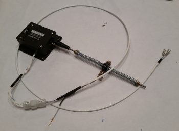
And a look at the entire Roll Trim system.

5-wire roll trim & ELT GPS cable complete!

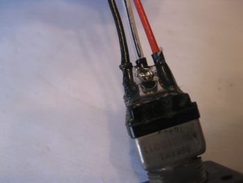
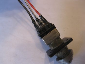
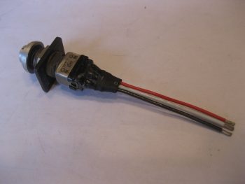
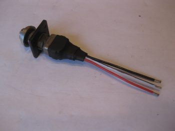
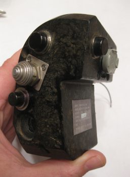
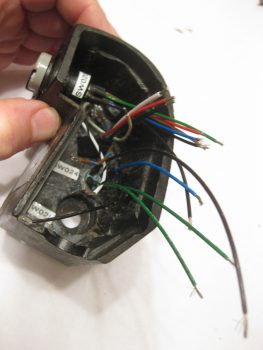
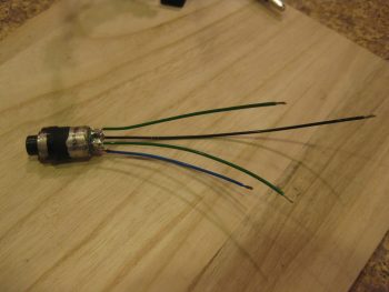
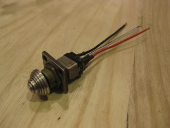
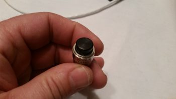
I was playing around a bit (dismantling) the odd, heavy, large joystick-type switch that came in the throttle handle when I found this guy buried inside of it.  It’s a rather large press-in-fit momentary on-off switch that I’m going to press into service as my GIB PTT button!

Serendipitous discovery of GIB PTT button!

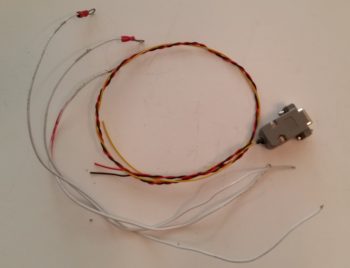
My final act of the evening as I watched Thursday night football was to finalize the rewiring of the TruTrak ADI wiring harness by twisting the whopping three 22 AWG wires together and then installing the backshell to the 9-pin D-Sub connector.  I included the originally installed harness wires in this pic to again show how huge they were/are (14-18 ga)!

Completed rewiring of TT ADI wiring harness

Tomorrow will be a light build day since I’m heading out mid-afternoon for a social engagement.  I will try to get a bit more done on the Triparagon structure though (and stop sloughing off since there’s no football games tomorrow!)


Chapter 22 – Infinity Stick Grip

I started out today cleaning up the RivNut installed on the triangular panel support.  I knife trimmed the excess 2-ply BID layup and pulled the protective tape from the top of the RivNut.  I then function tested it as you can see below.  Works to plan so far!

With the new Adel clamp in place for the Infinity stick grip cable, I could then check the proper slack for the cable, mount it in the Adel clamps, then mark the cable for cutting to length.

Measuring stick control cable for cutting

I pulled the stick grip out and took it to my mad scientist’s electrical laboratory upstairs. Before starting work on it however, I spent a good 1-1/2 hours reconfirming the wiring pinouts for the P5 connector.  I consolidated 4 ground wires coming out of the stick grip into 2 wires to give 5 open pins, which enabled me to piggy back 5 wires into the P5 connector: 4 for the roll trim servo (behind the pilot’s seat) and 1 for the ELT GPS signal (like many other builders have done, my ELT will be positioned on the outboard fuselage sidewall, on the inboard side of the right strake’s baggage compartment… so just aft & outboard of my right shoulder).  As I was configuring the P5B half (the stick grip side) of the connector, I went ahead and spent another good hour+ figuring out the P5A side of the equation, which is the all points yonder (Triparagon, PQD, panel) side of the connector. It took some time since this process required a good bit of verification & cross-checking with the various electrical diagrams and the component installation manuals.

I had already gotten a late start since I was up late (working on this build!) last night.  I ran out to run some errands in the late afternoon and to pick up some small 4-40 stainless steel screws from a local hardware store that still has a wall of hard-to-find hardware in their back room.  When I got back I toned out all my stick grip wires to check continuity and verify wire colors, since I had swagged some guesses on them as I was building the P5 pinout diagram. With my P5 pinout up to speed, I did some prerequisite tasks for terminating the P5B connector onto the stick grip such as printing out shrink tube labels. For the 5-wire roll trim piggyback cable I checked availability of parts, since I have 4-pin mini-Molex connectors on hand and I need at least a 5-pin (which actually means 6-pin). Again, I don’t want to use a 9-pin D-Sub here, so I added a couple of 6-pin connectors to the Stein order that I’m compiling.  Boy, it’s an obvious statement I know, but the nit-noy parts buying process for these builds is ENDLESS!

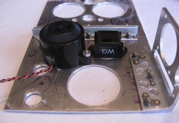
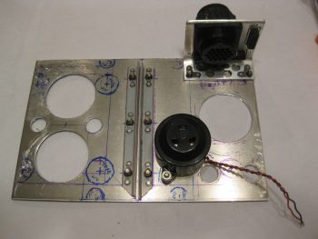
Ok, with it being a bit later in the evening, before I started on the terminating the P5 (B side) connector on the Infinity stick grip cable, I wanted to make a decent amount of noise on the Triparagon cross shelf.  Thus, I detoured from the stick grip cable for a bit to drill 10 new lightening holes into the cross shelf — 8 small diameter and 2 bigger diameter holes. The 2 bigger diameter holes, just to the right of the center brackets in the pic below, sit immediately above the mounted Piezo warning horn (bigger, lower hole) and the gear & canopy warning module that I mounted tonight (see next pic).

10 more lightening holes on cross shelf

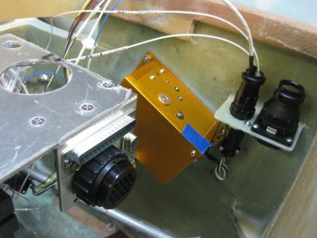
Yes, folks, it’s the marvel of modern technology! Getting a gear & canopy warning module into the space of a couple of stacked matchboxes . . . why it’s just pure science!  (ok, and integrated circuits… ha!)  Not wanting to NOT gain any progress on the Triparagon today, I mounted the nose gear & canopy warning module with some -6 CS SS screws.  As per usual, I drilled the countersinks on the topside of the Triparagon cross shelf, although admittedly one of the holes didn’t want to cooperate and the countersink is a bit larger, lopsided, and messier than I would prefer.  Still, once the screw is in & the module mounted it would be bit difficult to tell unless really looking hard at it.

Freshly mounted gear/canopy alarm module

I brought the Triparagon cross shelf back upstairs and weighed the whole thing without any mounted stuff.  It currently weighs in at 0.57 lbs, which when added to the Triparagon vertical plate at 0.7 lbs gives me a current total weight of 1.27 lbs.  This is about a quarter pound heavier than my 1 lb goal weight.  The prescription?  I gotta fever for some more lightening holes!  So back to the drill press for another round of sharp-bladed weigh loss!

I then started (finally!) on terminating the Infinity stick grip cable wires for the P5 connector, B side.  After taking a big breath and cutting the cable to length, I then slid the plethora of heat shrink tubes & labels onto the cable.  I then cut the outer cable jacket to expose the 17 inner wires.

Prepping control stick cable with labels

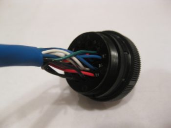
I didn’t take a bunch of sequential pics, so here’s what I did: I started off having to find & verify the pairs/groups of wires for each switch in the control stick.  As I found each new set, I would strip the end of the wires, terminate them with an AMP CPC socket, check continuity, and then mark them off the list.  I also used small pieces of masking tape to keep the pairs/groups of wires together.  After I terminated all the wires, which included 2 sets of 2-pair ground wires, I then double-checked the electrical continuity and then snapped them in place into the correct numbered socket hole.  I then rechecked continuity again just to ensure I had gotten it all right… which I didn’t.  I swapped the 2 green wires and had to pop them out and reinsert them into the correct socket positions.  I toned out the entire cable again to ensure the sockets were in the correct position with electrical continuity, which they were.

Stick grip cable wires terminated into connector

I then went down to the shop, measured the required length of roll trim & ELT GPS pigtail legnths at 10.5″.  Instead of using the 5-wire cable that I have (you’ll see that in pics tomorrow), I decided to simply use free 22 AWG wires. I actually started collecting the wires with the correct color codes (ie white with blue stripe, etc.) when I realized that instead of wasting my good multi-colored wire, I would simply use white wire and use a Sharpie to mark the correct color on the last couple of inches of the wire.  For the the two plain white wires in the bunch, I simply swapped out the white wire at pin #2 for a grey wire, so no confusion would set in while I await my 6-pin mini-Molex connector from Stein. I then terminated the 5 each 22 AWG pigtail wires with mini-Molex pins.

Stick grip cable wires terminated into connector

I then terminated the other end of the 5 pigtail wires with AMP CPC sockets. I verified that my crimps on the terminated wire ends were good by doing a continuity check on each wire.

Roll trim wires and ELT GPS wire

To keep the 5 pigtail wires under control, I threw on a small piece of black heat shrink.

Roll trim wires and ELT GPS wire

I then snapped the pigtail wires into their appropriate socket holes in the back of the P5 connector.  I also went to town on the cable with my heat gun and shrunk all the shrink tubing and labels in place.

Roll trim wires and ELT GPS wire installed

I then did a final continuity check on the pigtail wires, and with that all that was left to do was to mount the cable clamp, that I conveniently did not forgot to put on the cable this time!

Grip stick cable connector ready for cable clamp

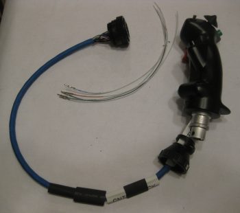
Here’s the Infinity stick grip cable terminated with the P5 AMP CPC connector and 5 pigtail wires that will go into a 6-pin mini-Molex connector.  If I wasn’t clear on the pigtail use before, it will allow the 4 roll trim/1 ELT GPS wires to transit into the P5 connector, but still allow me to disconnect the roll trim/ELT GPS cable at the 6-pin mini-Molex connector when I simply want to remove ONLY the Infinity stick grip and cable from the plane. Clearly, in this scenario, once the 6-pin mini-Molex connector is disconnected the 5-wire roll trim+ELT GPS cable would remain mounted under the right armrest.

Stick grip cable with roll trim pig tail completed

Here’s a couple closeup shots of the P5B connector with the cable clamp in place.

Grip stick cable connector cable clamp

Grip stick cable connector cable clamp

I realized as I remounted the control stick, ran the stick grip cable and screwed the P5B connector onto the P5A connector at the P3/P5 mounting bracket that I’m going to have to carefully trim the back outboard corner opening of the armrest to get that big mojamma P5B connector into the armrest!  After that it traverses through the lower instrument panel bulkhead hole fine.

Grip stick cable and connector test install

Also, I’m very happy with the stick grip cable run since it keeps the cable nicely tucked out of the way from the elevator control tube range of motion.

Grip stick cable and connector test install

Here’s a final shot of the freshly terminated stick grip cable connector and installed cable.

Grip stick cable and connector test install

Tomorrow I will continue to work on the 5-wire roll trim+ELT GPS cable  and try to finish up the Triparagon installation.


Chapter 22 – Introducing PQD Bracket

First off, as you can see I’ve settled on the acronym PQD, Panel Quick Disconnect, to describe the connectors and bracket that I’ll be employing to make the task of removing the instrument panel infinitely EZier than without this configuration.  Although there will be some wires & components that will not be disconnected, either through their location just off the upper main Aluminum panel face, or because their wiring is not conducive to being split by a mid-point connector (eg Avidyne IFD COM plug P1002 & Dynon intercom wiring harness).

Speaking of the “upper main Aluminum panel face,” after some impromptu research I’ve decided that since I’m keeping a very large portion of the original panel in tact for strength behind the Aluminum panel face, that I’ll be using 0.063″ 2024T3 for the instrument panel. I was actually in the process of ordering that panel from ACS, when I double checked my spreadsheet and lo & behold, I had a spare 2′ x 2′ panel on hand from years ago.  Woo-hoo!

Ok, back to the PQD.  I had originally ordered a 1/8″ thick 2-1/2″ x 2-1/2″ angled piece of 2024 from McMaster-Carr quite a while ago thinking that I would hang a bunch of stuff off these cross shelf overhangs in the same fashion that I’m doing now with the clearly much smaller sized 1″ x 1″ angled aluminum overhangs.  This angled aluminum extrusion was just too big & heavy to use in any reasonable quantity, plus as my Triparagon design matured I just didn’t have a need for it.  So into the massive spare pile of aluminum it went.

Then when I was finally hit between the eyes seeing Paul Dye’s panel on the VAF forum as I was trolling for pitot-static info, I finalized my decision to make my panel fully & EZily removable. So I had to get serious on both the quantity & type of connectors to use and where they would reside.  I had had a nascent thought all along of a drop down bracket on the aft right corner of the Triparagon cross shelf IF I did the fully removable panel mod.  Well again, it was time to get really serious so out came the big gun: the 1/8″ thick 2-1/2″ x 2-1/2″ angled 2024.  If you remember I posted a few days ago, over the Thanksgiving holiday, a mockup of my connectors on the end of this massive 2′ long piece of aluminum. With my electrical connections confirmed, and with the only mod to the actual connectors being that I swapped out the 19-pin AMP CPC connector for a higher capacity 24-pin connector (same diameter), I was ready to install the J3, J4 & P6 connectors into the PQD bracket, and of course make the PQD bracket itself.

I started by marking the connector outlines on the angled extrusion.
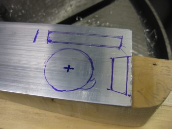
Designing Panel Quick Disconnect (PQD) connector bracket

I then used a hole saw to drill the 1-1/2″ diameter hole for the P6 AMP CPC connector.
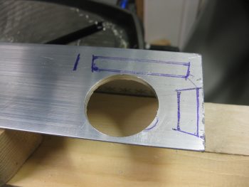
Making PQD connector bracket

Of course I had to check the fit…. looking good so far!
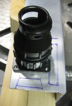
Testing P6 connector fit in PQD bracket

Then came the odd shaped 37-pin & 15-pin D-Sub connectors.  I figured this would be a total hand-jam custom build process (“custom” means it works fine, but it ain’t always pretty!).  I drilled some small starter holes, focusing especially on the corners.
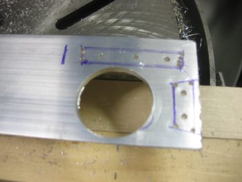
Drilling out D-Sub slots in PQD bracket

I then expanded out the center area holes with a large diameter drill bit, which is the same diameter as the width of the D-Sub connectors.
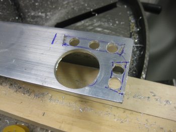
Drilling out D-Sub slots in PQD bracket

I then employed my jig saw –and a few expletives!– to finalize the cutouts for the D-Sub connectors.  Here’s a shot of the initial rough connector cutouts in the beginnings of the PQD bracket.
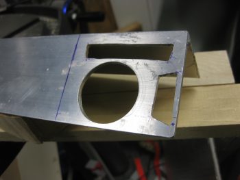
Connector holes made in PQD bracket

And another shot after I cut the bracket out of the angled 2024 extrusion (it was raining so I plunged forward using my Skil saw to cut the bracket out!).
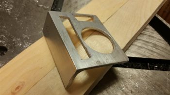
PQD Bracket

I then test fitted the connectors in the PQD bracket.
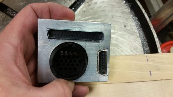
Connector test fit in PQD bracket

Here’s a shot of the backside of the connectors test mounted into the PQD bracket.
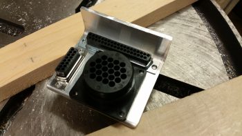
Connector test fit in PQD bracket

I then took the PQD bracket upstairs and mocked it up on my Triparagon cross shelf. After finalizing the mounting location for the PQD bracket on the cross shelf, I then digressed a bit from the PQD bracket and figured out where my first round of lightening holes would go on the cross shelf.
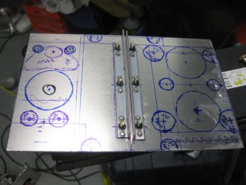
Marking Triparagon cross shelf lightening holes

I took the cross shelf and the PQD bracket down to the shop and proceeded to drill the mounting holes for the bracket into the bracket tab and the cross shelf.  I then added 3 K1000-8 nutplates to the PQD bracket mounting tab.  As you can see, I also drilled 4 lightening holes in to bracket’s mounting tab.
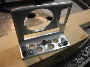
PQD bracket nutplate mounts

Here’s a view of the top of the PQD bracket mounting tab, with the flush rivets of the 3 K1000-3 nutplates visible.
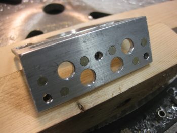
Mounting edge of PQD bracket

I then diverged from working on the PQD bracket for a bit and drilled out the first round of a bunch of lightening holes into the Triparagon cross shelf.  After finishing round one of lightening holes, I then went back to work on the PQD bracket and drilled countersinks for each of the 3 -8 screws into the top of the Triparagon cross shelf (shown 2 pics below).  I then mounted the PQD bracket to the cross shelf.
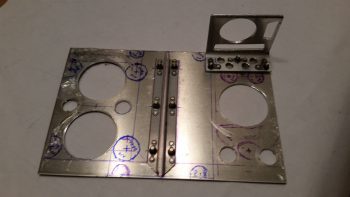
PQD bracket mounted to cross shelf

I then test fit the cross shelf back onto the vertical Triparagon plate.  Note the 3 countersunk -8 screws securing the PQD bracket into place.  (Note: while I was drilling the PQD bracket mounting holes through the mounting bracket into the cross shelf, the bracket misaligned slightly.  Nothing earth shattering, but definitely a slightly-sloppy mounting AND a loss of cool points!)
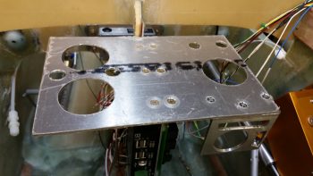
Cross shelf test fit with PQD bracket

After I finished with the PQD bracket mounting on the Triparagon cross shelf, I headed out the door to an auto racing shop just across the river in Maryland that sells some high end stuff.  I knew that they sold the same quick disconnect fittings that I’m using for my pitot-static system, so I wanted to take a quick break from the build and take a gander.  Well, it had been raining all day, but there seemed to be a lull.  So I grabbed the keys to the shed, pulled out my table saw and trimmed down the 1″ x 1″ angled 2024 aluminum extrusions that will serve as my Triparagon cross shelf mounting tab overhangs.

I trimmed these angled extrusions down on the sides that will mount to the front underside edge of the Triparagon cross shelf.  I took 0.4″ off, with the obvious resulting width of the top horizontal extrusion arm being 0.6″.  This took all of 10 minutes, and it actually started sprinkling again as I was putting the saw back away in the shed.  With my overhang extrusions cut, I was then off to the racing shop in Maryland.

As a reminder, besides simple weight savings, I wanted to trim down the left side angled extrusion, specifically, to allow me to mount the M760REM COM2 radio about 0.4″ forward on the left underside of the Triparagon cross shelf.  This served to better deconflict the mounting screw placements between the COM2 radio and the GRT GADAHRS that’s mounted on the top side of the cross shelf.  The right extrusion was merely along for the ride since I might as well make them symmetrical, right?!
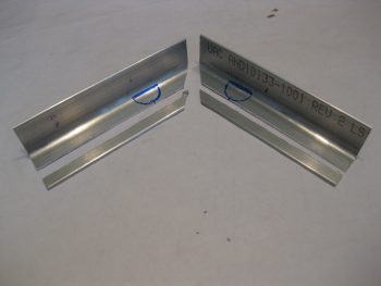
1" x 1" Triparagon cross shelf overhangs trimmed

Back from the racing shop, and my quest to replace the #40 drill bit that I broke (to no avail), I got back to work. After I collected up the right sized bits for drilling the connector mounting holes into the PQD bracket, I decided to take yet another slight detour to finalize a task that needed finishing: the right-side avionics wall bracket for the P3 & P5 connectors.  I drilled out the 8 total connector mounting screw holes and then did a final cleanup on the bracket by sanding down the edges and ridding it of excess glass fibers around all the holes.  I then test mounted both the P3 & P5 connectors.  I brought down the Trio A/P wiring harness from upstairs to test fit the other side of the P3 connector [confession time: I spent a good 10 minutes looking for that darn P3 connector just to finally realize that I had mounted it to the end of the Trio wiring harness pitch servo cable!].  You can see that I also set the 2 white auto trim wired into the back of the P3 connector as well.
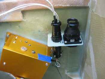
P3 & P5 connector bracket completed

Here’s a longer shot of the P3-A/P Pitch Servo and P5-Infinity Stick Grip connectors test fitted and mocked up in place.
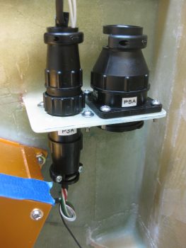
P3 & P5 connector bracket completed

Moving on with more connectors, I then mocked up the PQD connectors P6, J3, and J4.
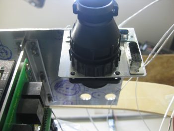
PQD bracket mounted - view from below

Since I was holding the camera down low taking low-to-high angle shots of the PQD bracket through the right leg hole, I took a few rounds to ensure that I got a good pic.  I had to leave this one in the mix since it looks like something out of Star Wars with a pure beam of energy coming out of the back of the P6 connector.  That’s right folks… no wires for me! Just pure energy transfer in my ship!  HA!
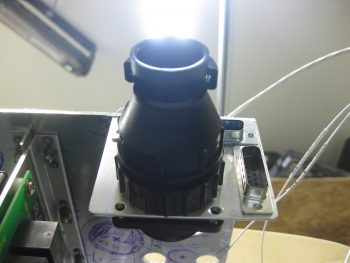
PQD turned on...pure energy!! ha! ;)

Here’s another shot of the PQD bracket and its connectors.  Note that although I originally wanted to mount the D-Sub connectors on the aft side of the PQD bracket (which would be the forward side of the plane), it initially appears that the connection hardware with the mating side D-Sub connectors will be tough to do if I left them aft-bracket-side mounted. I’ll play around with the hardware a bit, but I think that this will most likely be the mounting configuration for these connectors.
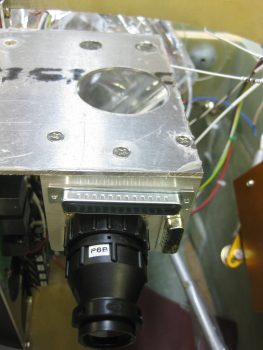
PQD bracket - top view

An issue that I noted was after I test fitted the aft side P6 connector’s cable clamp: Hmm, don’t think it’s going to fit since the gap spacing between the cable clamp and the panel is only about 2-5/8″.  It would most likely actually fit, but then of course all the wires would exit and then immediately have to take a hard 90° turn to get to their final destination.  Not good.  So . . .
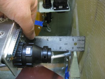
Uh-oh... Eh, a bit of a space problem!

Be gone vile & wicked cable clamp! (said in thick British villain voice… sorry, my Brit Canardian Peeps.  ha!)

Ok, much better!  As you can see with the P6 connector cable clamp removed I get about another 1.5″ clearance and 4″ spacing overall.  Still slightly tight, but since the GRT HXr EFIS is low profile on the backside this is EZily workable.
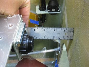
Ah, that's better... Bye-bye cable clamp!

And yet another shot showing all my current Avionics Bay connectors.
Connectors, connectors!

I reordered my blog post pics just a bit to make the topic flow a bit EZier to follow.  If you looked closely in my Avionics Bay pic above, you may have noted that I drilled a hole into the triangular panel support and added another RivNut for the second & final Adel clamp that will also be used for the Infinity Stick Grip cable routing from the stick to the P5 connector.  I also added a couple of layers of BID on the bottom side of the support triangle to beef up the RivNut mounting.
RivNut in for stick cable 2nd Adel clamp

Back on the Triparagon cross shelf, with the PQD bracket configured & installed, I then started in on some of the final pieces parts (aka “CrackerJack Bits”) that I need to mount to round out the final electrical system components install on the Triparagon.   I found a good spot for the Piezo Warning Horn on the right underside of the cross shelf. I mocked it up, ensuring it had good clearance with the vertical Triparagon components (it’s close to, but not touching, one of the mounting screws to the right side AG6 warning annunciator). I drilled the holes for #6 mounting screws and then countersunk the 2 screws on the top side of the cross shelf.
Piezo warning horn mounted on right side

Here’s a closer shot of the mounted Piezo Warning Horn with the #6 mounting screws installed.  I used standard nuts on the screws to mock up the warning horn & make it EZily removable.
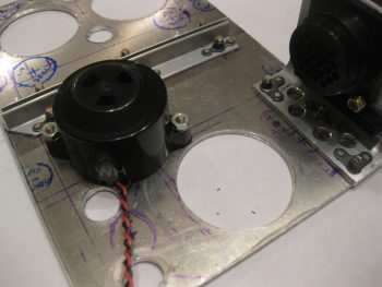
close up of warning horn mount

I then test fitted the Triparagon cross shelf onto the vertical plate to double check the clearance between the warning horn and other Triparagon components.  In the pic below you can see the 2 countersunk #6 screws, and the warning horn itself through the lightening hole.
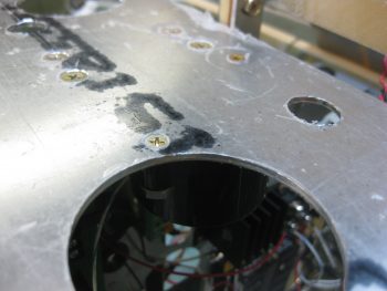
Piezo Warning Horn #6 CS screwsHere’s a final shot of the mounted Piezo Warning Horn on the right underside of the Triparagon cross shelf (pic taken from the front of plane).  You can see that it’s close in line to the wiring bundles that will spew forth from the PQD bracket, but also clearly not in the way either.
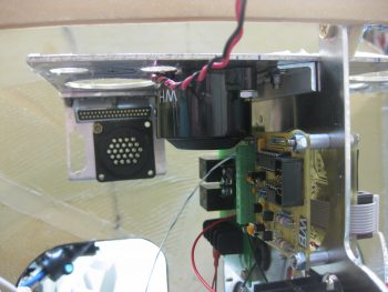
Piezo warning horn mounted

I then brought my cardboard component mockups that I made a year or so back to check out their general fit on the Triparagon cross shelf.  Below you can see the GRT GADAHRS (their new term for their new AHRS) and the Trig TT22 Transponder behind the GADAHRS.
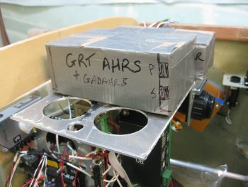
GADAHRS & XPDR mocked upAnother shot of the cardboard GADAHRS & XPDR mockups.
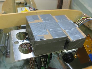
GADAHRS & XPDR mockups

Just an idea of the fit of the Trig TT22 Transponder on the Triparagon cross shelf.
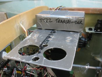
Trig XPDR mock up box

And the cardboard GADAHRS and XPDR on the Triparagon cross shelf with the rest of the left side Triparagon in view.
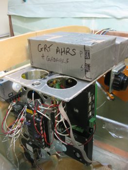
The whole shebang

Since there’s forecasted high winds tomorrow, and thus no flying, I’ll continue my quest to finalize the Triparagon cross shelf and resident components install.  I will be doing some more sideline wiring on my components since currently they’re EZ low hanging fruit, and don’t conflict with other parts of the build (like so many other build actions do at this point!).  It doesn’t look like to much longer before I’ll be back on the . . .  Yes, WHEEL PANTS!