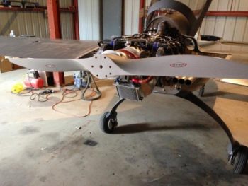
Chapter 14/23 – Engine Mount Extrusions

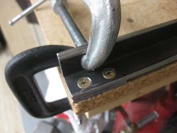
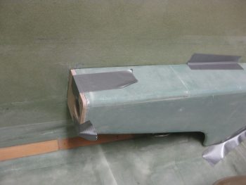
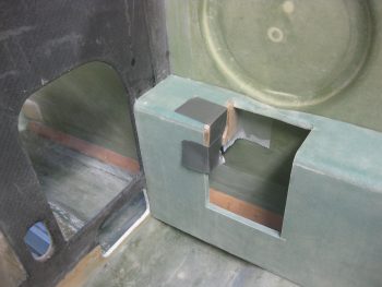
Today I started off by cutting the upper left 4130 steel engine mount extrusion into 8″ & 1.6″ lengths.

Cutting upper left engine mount extrusion

Cutting upper left engine mount extrusion

I then trimmed the lower 0.1″ reinforcement plate for a final fit to the upper left engine mount extrusion pieces.

Left reinforcement plate trimmed

I then drilled the countersunk screw holes in the upper left extrusion mount pieces.

Drilling holes in upper left extrusion

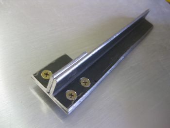
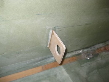
Here’s a shot of the 3/16″ countersunk screws mounted in the upper left extrusion mount pieces.

Mounting lower reinforcement plate

And all three 3/16″ countersunk screws mounted in the upper left extrusion mount pieces.

Lower reinforcement plate mounted

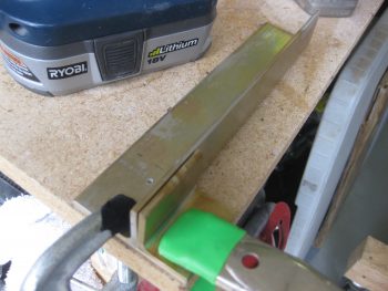
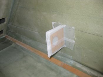
I then drilled the countersunk screw holes in the upper right extrusion mount pieces.

Mounting lower reinforcement plate

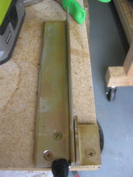
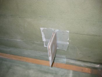
Here’s a shot of all three 3/16″ countersunk screws mounted in the upper right extrusion mount pieces.

Lower reinforcement plate mounted

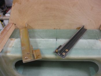
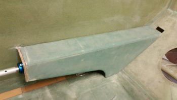
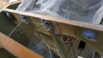
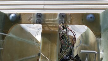
Below are the 3/16″ countersunk screws & lower reinforcement plates in place on the upper extrusion mount pieces.

Lower reinforcement plates mounted

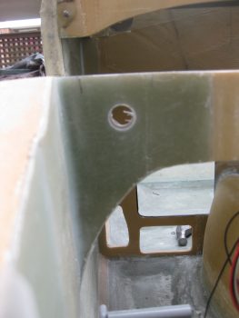
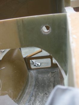
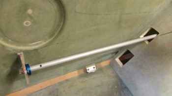
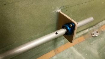
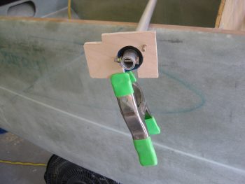
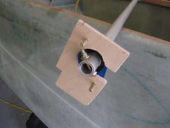
I then mocked up the CS105 control tube & test fitted it in place in the CS109 mount. With the CS105 tube moved inboard, the hole through the front seat will have to be widened just a hair in the area I’m pointing out with scribe in the pic below.

CS105 control tube mounted

CS105 control tube mounted

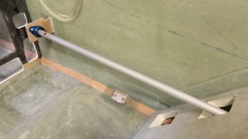
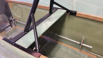
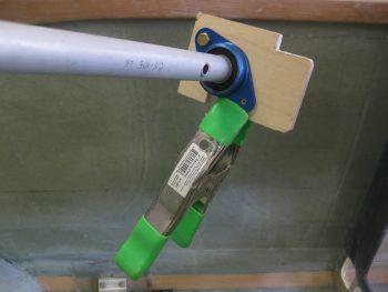
And did the same on the aft side with the CS105 control tube test fitted in place in CS118.

CS105 control tube mounted

CS105 control tube mounted

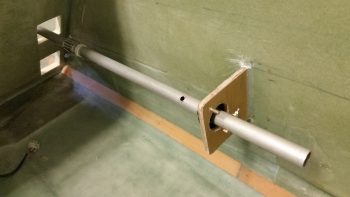
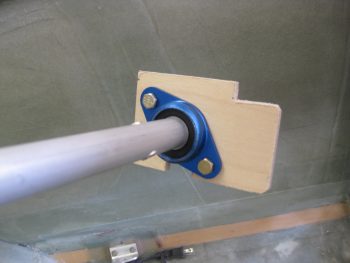
Here’s a shot of the CS105 control tube test fitted in place in both the CS109 & CS118 control mounts.

CS105 control tube mounted

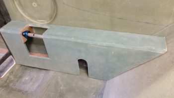
I then set the right side pilot arm rest in place, with the CS105 control tube test fitted in place.

CS109, CS105 & armrest

CS109, CS105 & armrest

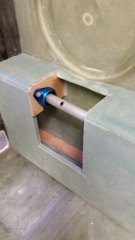
I then did the same with the GIB armrest, with the CS105 control tube test fitted in place. Thankfully, the fit on both forward and aft right armrests are fine.

GIB right armrest

Tomorrow I plan to work on the aft left arm rest and then start back on the final canard & elevator install.


Chapter 16 – CS109 & CS118 final install

Today I started out by laying up the 1-ply of BID on the forward side of CS109 that I had intended to yesterday, but needed to go with smaller corner layups in order to have CS109 taped in place to the right arm rest so that it would be positioned correctly.

Normally I would glass the aft side of CS109, but after reviewing the plans, and since I do have a small corner piece of BID on the aft side, I’m going to leave it until I glass the arm rest in place (yes, I am in the current minority of builders that still plans on glassing my armrests into place & not make them removable).

[Note: I cleaned up this layup a bit more after this pic . . . in case you’re wondering (smile)]

Glassing forward side CS109

I then sanded the cured BID on the aft control mounting bulkhead, CS118, and then redrilled the #12 holes.  CS118 is complete.

CS118 sanded & holes re-drilled

I then spent almost 2 hours cutting all the BID required to install the top & bottom engine mount extrusions (4 total) to the CS spar & longerons.  Probably not a very exciting pic… but cutting glass for nearly 2 hours isn’t exciting either!  ha!

BID for engine mount extrusions

Although towards the bottom of my task list today, I finally got sick of looking at all the peel ply boogers on the CS spar-to-fuselage layups, so I gave it a higher priority!  You may have noticed in my blog post yesterday the significant amount of dust & debri in the nose from mounting the canard (which is now gone…the debri, not the canard!)… with all that was going on I simply didn’t have enough time before heading out to Rough River for a good after action cleanup, and am just now getting around to it.  I spent well over an hour cleaning up all the layups from mounting the CS spar to the fuselage, and also the inboard holes in the CS spar forward face I filled with foam & glassed. If you remember, I made those holes for drilling the wing bolt holes.  I still need another good hour in ridding the spar (and then later the wings) of all the offending bondo.

CS spar to fuselage layups cleaned up

After cleaning up the aft side of the fuselage, I then pulled the peel ply and knife trimmed the CS109 front side layup.

CS109 peel ply pulled & knife trimmed

Again, I’m going to wait to glass the aft side CS109 until I install the right arm rest. Tomorrow I’ll sand this mount down and redrill the #12 holes.

Will glass aft CS109 when arm rest installed

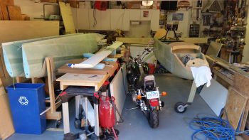
Well, tonight was finally the night!  I spent about 3 hours reorganizing, cleaning and straightening up the shop.  This is just phase I and I plan on knocking out phase II tomorrow.

Shop cleanup & reorg

The main thing I’m happy about is that I can walk to the front of the shop to back of the shop without having to low crawl under my CS spar.  Just 2′ to one side of the spar to pass, and I am one happy camper!

Shop cleanup & reorg

I don’t have a shot of it, but the final act of the evening was that I spent a good 30-45 minutes filing down & cleaning up the edges of the upper left 4130 engine mount extrusion. After another 15-20 minutes tomorrow, it will be ready to be cut to its final 8″ & 1.6″ lengths.


Chapter 16 – CS109 & CS118 control mounts

I started off today acting upon some information that I got from my buddy Dave Berenholtz down in OZ.  He said that his Long-EZ was built in 1987 and that over the years the requisite plan’s holes in the bottom of the Instrument Panel –with the foam exposed to air, etc.– have  deteriorated significantly from the edge of the foam not being treated.  This jived with what my Instructor from the EAA Composites Workshop stated when he said that builders should always cover exposed foam with either micro or flox.

So today, before I got started on re-installing the CS109 & CS118 control mounts, I decided I would get the lion’s share of this task knocked out.  I figured that if I channeled the foam in the lower Instrument Panel holes before I started any glassing, then I would use whatever leftover epoxy I had at each step to use for micro to edge these holes.

Foam edges on lower panel holes

After I used the Dremel tool to remove a small channel of foam around each of the Instrument Panel’s lower holes, I then cleaned up the dead glass from the previous install of CS109.

CS109 site & lower panel holes prepped

I then did the same thing in the back seat, and cleaned up the existing glass from the previous CS118 install.

CS118 site prepped for glass

I cut 4 plies of BID on the table (not shown), one for each side of the respective control mounts, and then set about to drill the #12 holes through CS109.

Drilling #12 holes in CS109Drilling #12 holes in CS109

Here’s a shot of the AN3 bolts test fit.

#12 bolt holes drilled in CS109#12 bolt holes drilled in CS109

I then did the same thing for the aft-side CS118 and test fitted those AN3 bolts as well.

#12 bolt holes drilled in CS118#12 bolt holes drilled in CS118

To ensure I could remove the arm rests after the 5 min glue stuck CS109 & CS118 to the fuselage sidewall, I covered the top inside armrests with clear packing tape.

Right armrest underside taped

I then 5 min glued CS109 in place to the fuselage sidewall, while taping it in place with duct tape to ensure it aligned properly.

CS109 5-min glued in place

Of course I did the same thing in the back for CS118.

CS118 5-min glued in place

The forward CS109 control mount wasn’t as solidly stuck in place with the 5 min glue, so I went ahead and worked the back CS118 mount first.   Below you can see that the 5 min glue did its job and kept CS118 right in place.

CS118 5-min glue cured

I whipped up some MGS285 epoxy with fast hardener, and then some flox, and added flox fillets in the corners.

Flox fillets on CS118

I then laid up 1 ply of BID on each side of CS118 and peel plied the layups.

CS118 glassed 1-ply BID each side

CS118 glassed 1-ply BID each side

Since I still needed the tape on the front side to secure CS109 in place, I simply laid up 1 ply of BID on each side, but kept each ply small at 2″ x 2″… just enough to lock in the position of the CS109 control mount & keep it aligned properly with the arm rest.  I then peel plied the layups [Note the micro in the foam edges of the lower instrument panel holes].

CS109 in place while BID cures

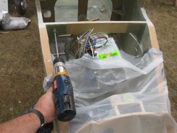
While the CS109 & CS118 layups were curing, I then drilled a #12 hole down into the upper left engine mount extrusion’s bottom reinforcement plate.  I then countersunk the hole in the outboard 2024 aluminum angle “L” bracket.  I didn’t want to drill the other 2 holes on the other side since I wasn’t sure how much compression there would be when the engine mount was actually bolted in place (the plans say 4 AN3 screws according to a CP… but I seriously don’t know where 4 holes would fit for AN3 screws.  There technically is 4 screws/bolts going through the extrusion plates into the lower reinforcement plate, IF you count the 1/4″ bolt that holds on the engine mount tube).

I did realize after I Alodined these parts (below) that I had a major brain SNAFU and should have at least drilled & countersunk the screws on the top (long) extrusion.  I could then have simply drilled the holes into the lower reinforcement plate later, since it connects both sides… oh, well.  No huge deal, just definitely not optimized as for as Alodine coverage.

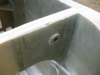
Drilling outboard engine mount tab

Now, my main Alodine goal for today was to at least get the Engine Mount Extrusions Alodined.  I cleaned all the parts with a quick wipe down of Acetone.  Then I cleaned them with a 3M pad and Simple Green, and rinsed them thoroughly.  I then took them outside and Alodined them.  In addition, I was also actually able to prep & Alodine the Aluminum parts for the wing bolt brackets that will allow me to mount the wing bolts in the spar quasi-permanently facing aft to greatly simplify wing mounting/removal.

Extrusions ready for Alodine

After I was done Alodining all the aluminum parts & letting them dry, I pulled the peel ply off the CS118 layups & razor cut the BID glass.

CS118 peel ply pulled & razor trimmed

Here’s a shot of the new & improved CS118 glassed into place.  Tomorrow I’ll finish sanding the edges & redrilling the bolt holes.

CS118 glassed & looking good!

The CS109 mount initial attachment layup came out fine as well.  I didn’t realize that I had floxed in such robust fillets, so that sucker will definitely be strong!  Tomorrow I’ll add another full ply of BID to the front and aft side.

CS109 ready for BID ply each side"Robust" flox fillets on CS109! ;)

I quickly double-checked the fit & alignment with the front right arm rest, and it fit great!

CS109 position is good!

Here’s the last shot of the evening (not, however, the last action of the evening since my hose sprung multiple leaks as I was Alodining this stuff, and my shop still needs some TLC to get some water out from underneath some stuff!!!)

You can see below that the 3 aluminum engine mounts and the outboard spar wing bolt brackets are Alodined.  Clearly I still need to finalize cleaning up the edges of the 4130 steel engine mount.

Alodined engine extrusions & wing bolt brackets

Now that I have a good bit of these of smaller tasks out of the way, I really do plan on attempting to reorg the shop tomorrow in order to get it prepped for finalizing the canard & elevators install!


Chapter 14 – Engine Mount Extrusions

Actually, engine mount extrusions were just one small part of today’s activities . . .

My goal today really was to get the new CS109 & CS118 plywood bulkheads cut and glassed back in place in the fuselage.  Uh, this didn’t happen.  Although I did get a lot done.  My secondary goal was as I got something curing (CS109 & CS118), I would then get the shop reorganized so I could build something, let alone just move around.

Let’s just say that there was a lot of “drag” today in that instead of things taking 1 or 2 steps, the prerequisite tasks of just getting materials out of the shop closet, or finding tools, took much more time than it should have.

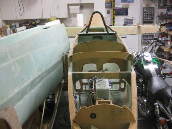
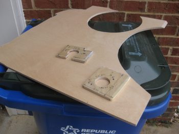
After I marked out the dimensions of CS109 & CS118, I then pulled out a scrap piece of the 1/4″ Finnish Birch plywood that is used for the firewall.  Since I had no other scrap plywood pieces big enough for either plywood bulkhead, I had to get into the closet, which was a feat unto itself!  ha!

Scrap Birch plywood for new CS109/118

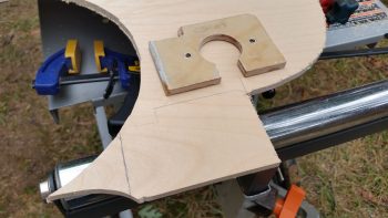
I found some good spots to cut out the new plywood bulkheads, marked them up & then cut them.

[I should state that this was not my first foray into cutting wood today.  I actually started by cutting the four (4) WA16 Spruce wedges for mounting the engine mount extrusions to the spar & longerons.  One of them needs to be a bit taller, so I will be re-cutting one more.  They are in a rough stage now & still need to be sanded. Sorry, the only pic I have of them currently is at the end of this post.]

Re-cutting CS109

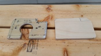
Here’s a shot of the new CS109 plywood blank.

CS109 Birch ply blank re-cut

And the same for CS118.

CS118 Birch ply blank re-cut

As a reminder, the reason why I’m redoing the CS109 & CS118 control stick mount bulkheads is due to the fact that the Cozy Girrrls sell the Cozy style stick mounts (I’m guessing….) for the Long-EZ.  In the pic below, which I shamelessly stole from my buddy Dave Berenholtz’s site, you can see that the CG stick mounts straddle the CS105 control tube, whereas in the original Long-EZ the control stick merely bolted to the inside the CS105.  If this lost 3/4″ offset to the inboard side of CS105 isn’t accounted for, then clearing the side wall either top or bottom of the stick will be problematic.  Interestingly, and as I told Dave in an email, since I widened my fuselage and my armrests just a hair bigger, I had already kicked the holes in CS109 & CS118 inboard by 0.4″.  I might have actually been able to get away with doing nothing, but it was good that I took these off. The good part is that I only had to move the holes another 0.35″ inboard.

Cozy Girrrl Control Sticks

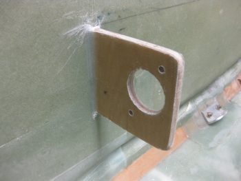
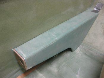
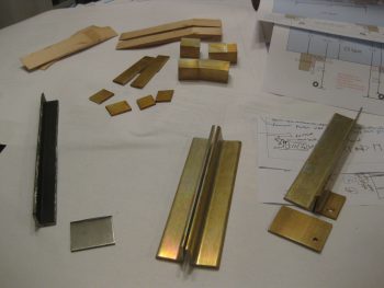
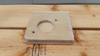
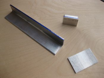
I then cut the 1/8″ thick 2024 aluminum bottom engine mount extrusion support plate.  My upper Right side extrusion originally had 1.5″ x 1.5″ legs, but since I didn’t want the top vertical leg extending so far up above the longeron, I trimmed it down to 1.25″.  The horizontal leg I left at 1.5″ on the INBOARD side.  I planned to trim down the OUTBOARD 1.6″ long extrusion to 1″ wide (see below).  Thus, I needed the bottom support bracket to measure 1.6″ long  x 2.5″ wide.

1/8" bottom 2024 extrusion plate cut

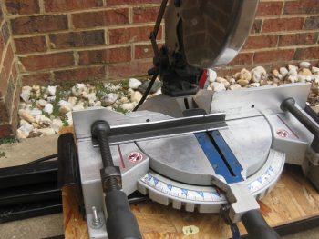
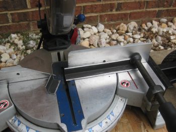
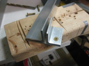
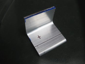
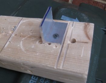
To trim the OUTBOARD 2024 upper right engine mount extrusion to 1″ wide, I needed to secure it so that the miter saw wouldn’t chew it up.  I knew it needed at least one bolt hole in the bottom leg of the plate, so I marked a spot for a #10 hole.  As you can see, I marked the 1″ cut line as well.

Trim 1.6" extrusion to 1" wide

I then drilled the #10 hole and mounted the extrusion piece to a scrap piece of wood.

Trim 1.6" extrusion to 1" wide

I then cut the extrusion down to 1″ wide on my miter saw.

1.6" extrusion cut to 1" wide

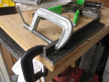
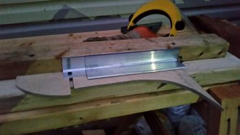
I then made up a quick jig that made it so that a 2×4 was the same height as the 1.25″ high 2024 engine mount extrusion.

2024 extrusion jigged for router

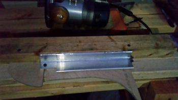
I then took my router with a 1/8″ roundover bit and radiused the edge of both short & long engine mount extrusions.  Again, these are still in the rough stage and I have to finish cleaning them up.

Radiused 2024 extrusion top edge

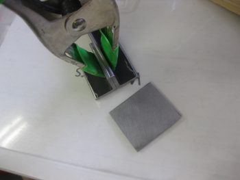
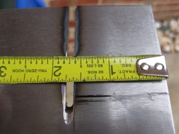
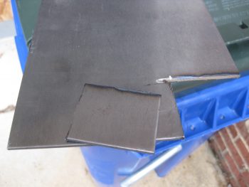
I then cut the 0.1″ thick 4130 steel bottom engine mount extrusion support plate for the upper left engine mount.  I didn’t have any 1/8″ thick 4130, and honestly didn’t order any because 4130 is some amazingly strong stuff, so 0.1″ will do the trick…. and with slightly less weight.

I cut the first cut using another chop saw I have with a metal cutting blade on it.

0.1" thick 4130 bottom extrusion plate

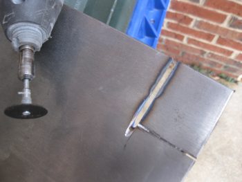
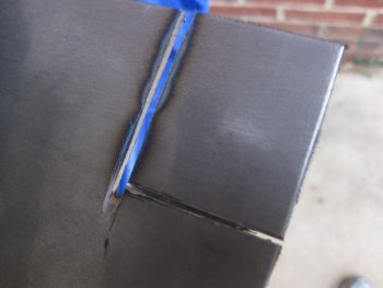
For the 90° cut I simply pulled out the Dremel tool and used it.

Dremel tool for final cut

It only took a few minutes to cut through this steel.

Dremel tool for final cut

And voila!  The bottom 4130 support plate for the engine mount extrusion on the upper left side.

0.1" thick 4130 bottom extrusion plate

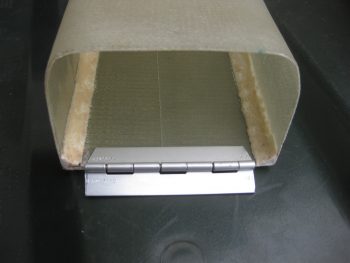
Since I had the saw out, I grabbed a small aluminum hinge that I had set aside a few weeks ago for the battery compartment mounted tool box.  I then cut a hinge for the tool box.

Tool box hinge cut

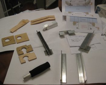
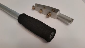
Below is a shot of todays machinations.  In addition to the tool box hinge above, I also trimmed the GIB handle tube to length (6″, at least for now) & cleaned it up.  BTW, it weighed in at a whopping 0.086 lbs, and that’s with the grip in place.

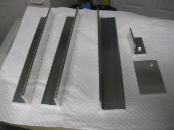
Yet another bunch of material I cut but didn’t get any pics of are the pieces that will make up the U-channel wing bolt securing bracket (in the middle of the pic below).  This will allow me to put the wing bolts in the spar facing out (aft) and be secured against moving.  This will greatly facilitate the speed & ease of putting the wings on & off.

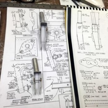
A day's worth of work!

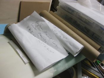
You may also note that in the pic above I included printouts of my engine mount extrusion diagrams/notes that I updated yesterday.

I may get an hour or two in tomorrow evening, but basically I won’t be full on in the shop again until Monday.  Pretty much all the parts I cut today need to be sanded, shaped, deburred, etc.  I then really need to get the shop reorganized after I get all these smaller bits ‘n pieces squared away.


Chapter 22 – Updated/new Wiring Diagrams

Today I spent the first half of the day getting a safety inspection done on my motorcycle. Just as they were finishing up the inspection it started to drizzle, which then turned into a fairly steady light rain for most of the day.  Which of course meant not getting the garage organized since most of the stuff has to come out so that I move & reorg the stuff inside.  Oh, well.

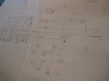
So, after the inspection was complete I did a fair amount of research on the heating system.  That rolled into updating a few wiring diagrams to reflect the updated electrical requirements, which included: the removal of the GIB Infinity control stick, resulting in the need to update the switch diagram, and of course updating the newly created Heating System diagram (these 3 are shown below).

Updated/new wiring diagrams

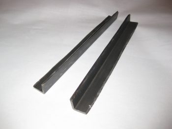
I then went down to the shop and finally cut the 1″ x 1″ Chromoly steel engine mount square tube extrusion into 2 “L”-shaped angled pieces. I know some may question exactly why I’m throwing in only one mount of 4130 steel.  Well, I was actually going to install 2 4130 steel mounts catty-corner from each other, but when the bottom mounts required the use of 3/16″ angled extrusions, I simply decided that between the weight and cost of buying more/thicker 4130 steel, I would punt and simply put only the one top side in.  Yes, I considered both top engine mount extrusions being 4130, but now with my engine weighing in heavier, I’m going to employ a little Operational Risk Management here and just go with the one side to keep the weight down, and to keep from having to buy more metal!  A little odd?  Perhaps.  But I’m going to be a little eccentric and go with this!

By the way, after I got it all cut, I matched it up to the engine mount and it was a good match!

1" x 1" 4130 Chromoly engine mount

Ok, perhaps tomorrow I’ll actually get around to reorganizing the shop in order to be able to move around and build in it!


Chapter 23 – Silver Bullet Ordered!

I’m still in the throes of researching, documenting and integrating the ton of info I acquired at RR.  I’ve spent a fair amount of time on the phone, collectively, with Gary Hertzler regarding the prop, Sam from Saber Manufacturing regarding the prop extension, and my engine guy, Tom Schweitz, from Aero Engines in Winchester, VA regarding my engine.  It was good to reconnect with Tom after over a year having talked with him last since not only did I get some refined engine specs for Gary so he could build my Silver Bullet, but things have changed A LOT in the aircraft engine world . . . e.g. ECi no longer exists since Continental bought them out!.

[One quick note on ECi: since ECi no longer exists, Continental is apparently not overly concerned about hawking it’s wares to the experimental market.  Tom noted that if I have an issue in the future with ONE of my tapered-finned cylinder jugs –an ECi exclusive product– that I could quite possibly have to buy FOUR new jugs since the tapered-fins are no longer in production!  He has a set of 4 new certificated ECi Nickle+Carbide cylinder jugs that he’ll swap out mine for free… well, actually the cost is about 8 pounds added back on my engine!]

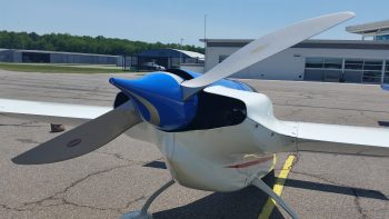
Ok, the good news is that I got all the info I needed for Gary and the proverbial informational cats were herded & coordinations made with all the players concerned regarding the prop.  The bottom line is that I got my order form filled out and sent off to Gary!  So within the next couple of months I should be the proud owner of a Hertzler Silver Bullet prop!

Marco's Silver BulletNate Mullins' Silver Bullet

I tried to find a stock photo, but couldn’t so here’s a couple shots of Silver Bullet props on my buddy Marco’s plane…


. . . and on Nate Mullins’ Long-EZ:


Besides working to get the prop ordered, I’ve also been working on an ACS order, a McMaster-Carr order and I just saw an email where Wicks Aircraft is having free shipping tomorrow on any order over $100.  I’m trying to finalize a few more pieces of 4130 and aluminum that I need, so I was figuring those out before submitting those respective orders.

One piece of aluminum in specific was for the GIB control stick.  I made a huge design departure on my aircraft where the GIB stick is concerned, which I’m very grateful that I made the discovery on how exactly it works back there.  Why the change?  Well, after spending a considerable amount of time in the back seat of Marco’s Long-EZ, I realize that during any period of heavy control usage: takeoffs, landings, pattern work, etc. that I have to move my right leg over to one side ESPECIALLY if the stick is mounted (his is removable).

When I queried the old guard on this, including Terry Lamp, the builder of Marco’s bird, they all said to make the stick removable!  It’s interesting how it takes a bit to reset our own paradigms, since mine in this area had always been to have the back seat control stick hard mounted.  Somewhat of an instant replacement (as JD sells it!  Good job JD! ha!) in case the front stick has issues.  After the flight back to Chesapeake from RR, I concluded that the only real logical thing to do was in fact make the GIB control stick removable.  With the design of the right side arm rest and the engineered plans version of the flight control system, there’s no viable way of getting around NOT having a permanently mounting control stick if you want to save the GIB’s thigh from being pummeled black & blue during any maneuvering flight.  Ok, big breath, big sigh … AND decision made to not hard mount the aft Infinity Control Stick!  In fact, it stays at home as an extra stick and instead a simple, lightweight, removable stick gets put in its place …

something like this:

New removable GIB stick

I dug out the control stick that I bought from the Cozy Girrrls, measured the OD at 0.617″ and then found some spare 2024 tubing stock that fit it.  The ID of this stock is 0.634″ and the OD is 3/4″.  I had some spare foam handle grips that I got from McMaster-Carr, so I threw one of those on the end.  Wow! It fit and felt perfect!  Done!  For final measure, I took a plastic cable channel insert that fit into the end & slid that sucker into place.  I can always swap that out, but for now –once I cut the tubing to length– I’m calling the GIB control stick COMPLETE!

Tomorrow I plan on getting the shop organized, taking into account the CS spar now mounted permanently on the fuselage… yes, that beast takes up some space!  Then I’ll continue for another few days to work these odd ‘n items before getting back to finalizing the canard & elevator install.


Chapter 23 – Prop Selection, etc.

When I got back from Marco’s place in Virginia Beach last night, I pretty much just decompressed from a very busy past couple of weeks.

Today was mainly about getting organized for the upcoming build.  I had a myriad of items on my list from RR that I wanted to capture (read: not lose!) & filed away in the right spots so that I could find them again.

I started out today like I do many build days by going down and grabbing breakfast just down the street from me.  While there, I wrote out my task list focusing on the myriad of the “little things” that need to get done.  I want to spend a few days to a week getting some of these ‘minnows’ knocked out before heading on to the big fish.

After I got back to the house, I spent a good hour updating my parts tracking spreadsheet, and tweaking my upcoming ACS order.  I did a good 45 min more of research on CAMLOCs and CLOCs (Skybolt) to figure out what specific parts I need and also refine my 1/4-turn fastener requirements for the entire airplane.

I mentioned in my project update that while at RR, between polling builders & fliers on their prop choice, flying in front of the Silver Bullet first hand in Marco’s Long-EZ, and having a quick discussion with Gary Hertzler, I made a final decision to go with the Silver Bullet prop over the Catto 3-bladed prop.  I will admit that with so many folks happy with their Silver Bullet props, that I can’t see (or justify) spending almost $2,000 more for a Catto prop when the Silver Bullet gets such rave reviews.  And to be clear, this in no way diminishes my opinion of Catto props.

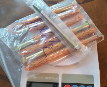
So, while out to take my truck to a service station for its annual safety inspection, I stopped at Lowe’s and picked up a Grade-8 7/16″ x 6″ bolt to use as a good estimate for comparing the weight of my current on-hand 1/2″ x 6.5″ prop bolts to the weight if I were to drop down to 7/16″ diameter prop bolts –which is what I hypothesized would be used for the Silver Bullet.  After some extrapolation to account for the 1/2″ shorter bolt, and weighing all the extraneous washers, etc., I concluded that using 7/16″ prop bolts vs 1/2″ bolts would save me 0.87 lb. … at the very aft end of my airplane.  That’s fairly significant considering weight & balance on these lighter birds.

Weighing 7/16" vs 1/2" prop bolts

Now, I did all this due to the fact that I had decided to go the 3-bladed Catto prop route a long time ago.  In fact, in a discussion with Craig Catto back in early 2013, he stated that with an IOX-340S engine I should be using 1/2″ bolts to mount one of his props. Thus, when I had Sam at Saber Manufacturing make my 8″ prop extension I had him configure it for 1/2″ prop bolts.

Jumping ahead to present day, with weight data in hand, I called Gary Hertzler to discuss using 1/2″ prop bolts with the Silver Bullet.  He said it could be done, but that the optimum size prop bolt would be 3/8″!  Wow, even smaller than I had estimated from my layman’s research.  Gary said to check with Sam since there was a good chance that Sam could merely redrill the smaller holes for 3/8″ bolts in-between the larger 1/2″ holes on the aft flange of my prop extension.  Well, sure enough Gary was right and Sam is wiling & very able to do exactly that.  And since I opened up the prop extension box for the first time since 2013 –with all the components new & unused– Sam will simply swap out all the 1/2″ bolts & components for the 3/8″ versions, including the crush plate.  With that, this completes all the prerequisite planning & coordination and means that I will pull the trigger here soon to become an official Silver Bullet slinging Canardian!

Moving on . . .

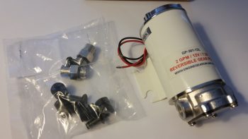
While at the RR Saturday evening Central States Association (CSA) meeting hosted by Terry Schubert and Nick Ugolini, I won the auction for one of Buly’s Oil Heat Pumps that I’ve been trying to get my hands on since I learned about them a year or two ago.  Luckily, I was able to get this thing WAY cheap and saved well over $100.  Just another plus for such an awesome RR!

Oil Pump for oil heat system

Last night I took the plunge and spent about 3 hours building my electrical diagram for the Oil Heat System in my bird.  I still have some more research to do since specifics on this system are vague at best.  After a good discussion with Greg Norman at RR, I’ve reached out to him to get some specifics on his install since he also has this oil pump.  Here in the near future I’ll discuss with Buly as well to finalize the architecture.  Of course, I’ll be performing a fair number of tests as well to ensure the circuitry is good before this system actually gets installed.

One final important point to note from RR.  I had a good discussion with Mike Toomey on wheel pants.  He gave me a number of tips on how I could continue with my install now, but by minimizing the actual tire cutouts on the bottom of the wheel pants I could then do a final configure on the pants after my 40 hours are flown off and simply widen the pant holes for the wheels in relation to the wheels after I do any mods.  With the advice I got from Mike in my back pocket, I’ll be moving forward with a near-total install of the wheel pants after I get the low-hanging fruit task list knocked out and the canard & elevator install finished.

Ok, back to work!


Chapter 12 – Canard mounting bits

This morning I finished tweaking last night’s blog post & updated my to-do task sheet for mounting the canard.  Not a lot left to do on the actual canard mounting itself, but I will be working on mounting the elevators & fitting them to both the canard & the fuselage sidewalls.  I’ll then of course have to fill in some fuselage sidewall in the corner of the F22/F28 shelf once I account for where exactly the elevator tubes will traverse the fuselage side walls.

After getting the requisite administrivia out of the way, I took the canard out to the fuselage and mounted it with the AN4 bolts into the freshly floxed-in CNL bushings.  Wow, is that fit TIGHT!  I didn’t realize why it was SO tight until I tried sliding an AN4 bolt into one of the CNL bushings even without the canard on… Whew, that is tight tolerance!

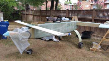
As you can see my canard stayed level. I checked the sweep and am still showing about 1/8″ off on one side, but I’m certain I can clean that up.  I guess this morning’s canard mounting is truly the first real test, eh?!

Canard fit with AN4 bolts in CNLs

Happy with this morning’s results, I was running around cleaning up & prepping to put the fuselage & wings back in the shop –which of course I still don’t have full on access to via the big garage door.  I then got a call from the garage door company saying that they were going to be a couple of hours late.  Well, enough time I sez to myself to flox in & glass the canard lift tab nut plates!

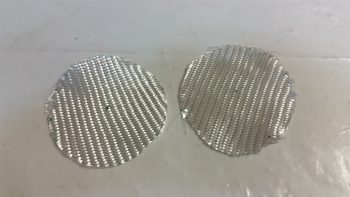
I grabbed some scrap BID and cut it into two 3″ circles, one BID ply for each nutplate assembly as per plans.

BID for canard mount nutplates

I prepped two slightly shorter AN4 bolts with a light coat of grease on the threads to keep those guys from becoming a permanent part of the nutplate assemblies, and then I pre-deployed my stuff to the fuselage.

After I was all prepped, I then whipped up some epoxy and flox with fast hardener and glassed these suckers in!  (Of course Marco called just as I started . . . persistent bugger in trying to slow my build down! Haha!)

Canard mount tab nutplates

Here’s another shot of the floxed & glassed canard lift tab K1000-4 nutplate assemblies. (Guess my aft side F22 needs some TLC… and cleanup, huh?)

Canard nutplates floxed/glassed

Ok, THIS will be my last post for a few days.  The garage door guys just called and will be here in the next 30 minutes.  I have to finish packing and get read to drive to Chesapeake, VA to meet Marco and prep for our Long-EZ flight to RR tomorrow!

I’m going to post the following pics without commentary until later on, I think their self explanatory of me breaking down the airplane and putting into my garage that now has a working door!

Final mockup with upper cowling.

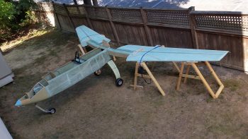
Test fitting upper cowlingMocking up upper cowlingBreaking it all down!One last shotBreaking down wings & fuselage

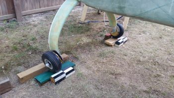
Shimming in wheel supports

Main gear supports

Longerons still at zero degrees!

Fuselage STILL at 0 degrees! :)

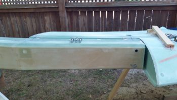
Removing wing bolts:

Left wing bolts out!Right wing bolts out

Wings detached

Wings unmountedDelinking from the mothership!

Moving fuselage back into shop:

Movie' on!We have separation!Tight fit! How'd that happen?!Cruz' in style!Puttin' 'er away!The Eagle is in the Roost!

Just wings . . .  again.

Breaking down wings & fuselageBreaking down wings & fuselage

Left wing on wing dolly.

Left wing on wing dolly

Getting there!

And there was one....

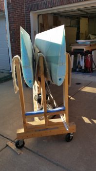
Both wings on wing dolly.  Note that I cut up some old carpet to make cradles in order to lift up the outboard wings to level.  Should come in handing while working on the ailerons.

Wings on dolly with new cradles

Tight squeeze, but it all fits!

It all fits! (barely! ;)

Side yard is back to normal!

Empty space... again.

Hope to see you at Rough River!  Cheers!

Chapter 12 – Canard Installed!

I started out today by double checking my BID spacer pad layups on the front side of the F28 bulkhead.  The left-side 12-ply spacer came out fine, but the single ply on the right side seemed to have some issues (i.e. delam around the #10 hole) … no worries since this is mainly for spacing and I can clean it up later.

I redrilled the #10 hole into the canard the doubler on the face of F28 (I also redrilled the #10 hole into the top alignment tabs).
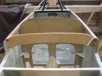
F28 BID pads

Here’s a closeup of the 12-ply BID spacer laid up on the front side of F28.  Just as a point of note, since this a spacer and not structural I used my old batch of MGS 335 on this so as to not waste the good stuff!
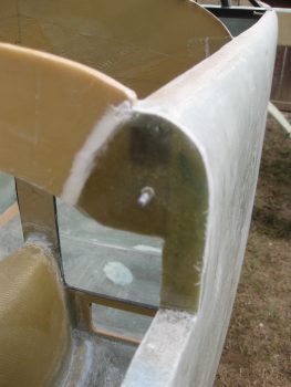
Left F28 12-ply BID pad

With the new spacers built into the airframe on the face of F28, I gave them a test run when I re-installed the canard.

The left side alignment tab was leaning forward just a hair more than I liked, creating a gap towards the top where it should have been much closer to the F28 12-ply BID spacer.
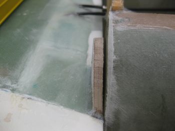
Slight gap between left tab & F28

I clamped the left alignment tab tight against the new 12-ply BID spacer on F28 & then very carefully hit it with a heat gun.
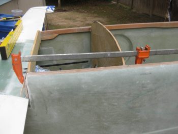
Clamp & heat to remove tab gap

I left the clamp on the alignment tab for probably 45 minutes and when I finally popped off the clamp, the alignment tab looked much better . . . well . . . aligned!  ha!

I’ll make a point here that after installing the canard this go around I then measured my left and right sweep from my center measuring block clamped to the top CL of the CS spar, as I had a myriad of times.  However, I did it while I still had the left side alignment tab clamped tight… and it showed.  I’ve been normally getting 0.06″ delta max between each side on sweep, and this time it was about 1/8″.  This of course went back to normal as soon as that clamp came off, although it may have been exaggerated just a hair by the shenanigans of that 1-ply of BID on F28 over on the right!
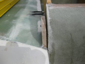
Left alignment tab closer to F28

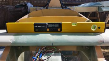
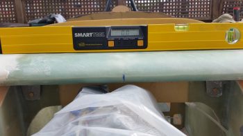
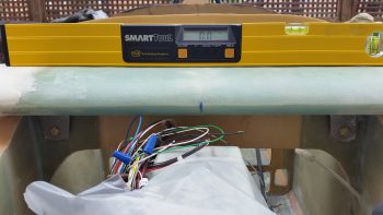
With sweep looking good, and it being the first official trial run of the day on the canard, I fired up my water level and immediately got this!  It may be a good day Maynard!  I also confirmed this with my digital level at the canard CL.

Right side water level:
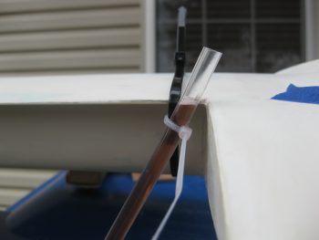
Right water level line

Left side water level:

Left water level line

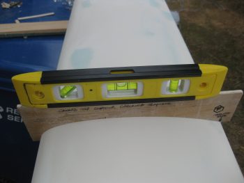
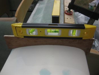
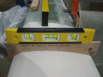
I then honed in on setting the incidence.  I’ve come to the conclusion that somewhat like my fuselage, my canard too has a very slight twist.  This may be (in part) due to the fact that I got the cores from Feather Light and they are still using the hotwire method off the original templates.  Don’t get me wrong, they make a quality product, but there were some minor idiosyncrasies with the canard cores.  Plus, obviously my being a Neanderthal builder clearly doesn’t help! Ha!

I have to tell you that I would probably freak out a bunch more if I didn’t consistently see Burt making allowances for us lesser beings in the plans.  Chapter 12 says if one has a twist in one’s canard, then one should mount it with that in mind and average out the twist in one’s canard: “If your canard has a slight twist, set the average incidence equal to the longerons.

Yes, there are those among us who would willingly cast the first “there is no such thing as a slight twist!” and/or “rebuild! rebuild!” stones, but I am more of the mind & in line with many of our pragmatic generals who say things like: “perfection is the enemy of good enough.”  Not that I don’t strive for perfection, I just clearly fall short quite often in this nebulous world that we call a Long-EZ build.  Thus, as John Roncz himself (relayed via Marc Zeitlin) once told a pummeled-by-peers Cozy builder: “see how it flies before you change anything” (paraphrased)… I think I too will do the same.

End Rationalization Transmission!

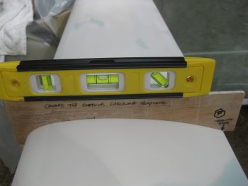
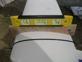
Therefore, without further ado, here are my incidence readings, starting from the canard right outboard side and moving to the left side.  You’ll note the right is LE high and then eventually makes it way to LE comparatively lower on the outboard left side.  One point of note, after messing with this for hours, my tolerance standard became anything within the inner most hash marks on the level.

One final point of note.  I find it amazing that I can sight down the canard and barely see any twist, with all look nice & laser straight, but this template definitely does do its job by finding that twist in regards to incidence.

Right canard: Outboard to inboard.
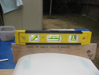
Outboard right incidence60% outboard right incidence

Inboard right incidence


Left canard: Inboard to outboard.
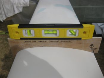
Inboard left incidence

~mid-point left incidence

75% outboard left incidence

Outboard left incidence


I spent another half hour tweaking the SWEEP, DIHEDRAL and INCIDENCE.  To tweak the dihedral & incidence just a hair more, I clamped the right side canard down just a smidge… which totally did the trick.
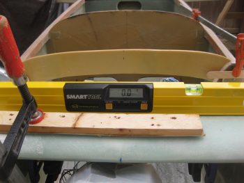
Canard level when #10 pilot hole drilled

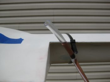
With everything looking good and all my variables locked in place, I pulled the trigger and drilled out the canard main mounting tabs with the long #10 bit. [Note: Although it looks like I’m ‘free-handing’ it here with the drill, I’m not.  I have small level with “V” grooves on the bottom that I actually hold on the drill bit shaft and I also set a 2×4 90° from the canard face close to the drill.  It may not be a perfect 90°, but it’s pretty darn close.]
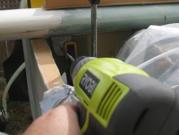
Drilling main canard tab #10 pilot hole

I started with the right side bolt and made sure everything stayed aligned by quickly checking my alignment variables again.
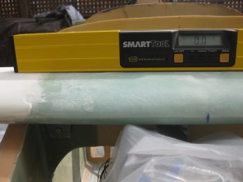
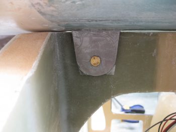
Main canard tab AN3 bolt installed

Main canard tab AN3 bolt installed

With the right bolt in place, everything still looked fine so I drilled the left side mounting tab with the #10 bit.  Below is a shot with both AN3 bolts in place on the main canard mounting tabs.
Canard mounted with AN3 bolts

Looking a lot more official on the canard mount with AN3 bolts actually keeping the mounting tabs in place to F22!
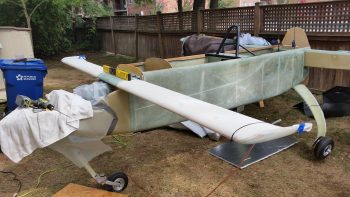
Canard mounted with AN3 bolts

With the lower tab pilot holes drilled and the correct position of the upper alignment tabs confirmed, it was then time to glass the aft & lower side of the alignment tabs with 4 plies of BID.

I started by sanding a radius at the Birch plywood tabs and the canard TE junction as per plans.
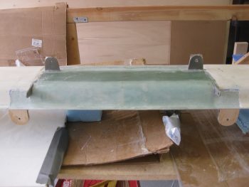
Glassing upper alignment tabs 4-ply BID

I then laid up 4 plies of BID on each lower side of the canard onto the tabs, and peel plied the layups.
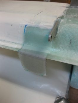
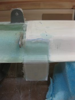
Glassing upper alignment tabs 4-ply BIDGlassing upper alignment tabs 4-ply BID

Here are the tabs after I pulled the peel ply, razor cut the overhanging glass & then sanded the edges .
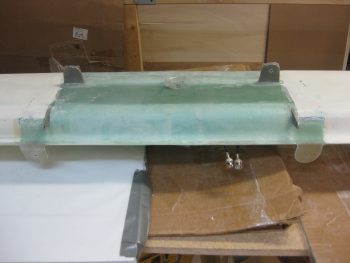
Alignment tabs cured & #10 holes redrilled

I then re-drilled the #10 hole into the alignment tabs.
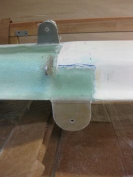
Alignment tab cured & #10 hole redrilled

I gathered up my CN2s (that I bought from the Cozy Girrrls).
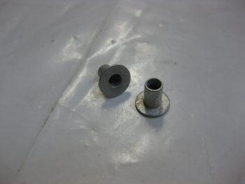
CN2 alignment tab bushing

I then drilled the out #10 holes in the alignment tabs to 1/4″, since the outside diameter of each CN2 bushing is 0.243″.
Alignment tab holes widened to 0.250"

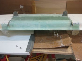
I used wet flox to install the CN2s into the upper alignment tabs.
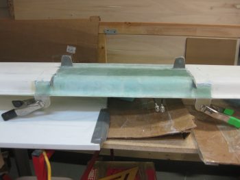
CN2 bushings floxed into alignment tabs

Here’s a close up shot of a CN2 installed into the upper alignment tab.
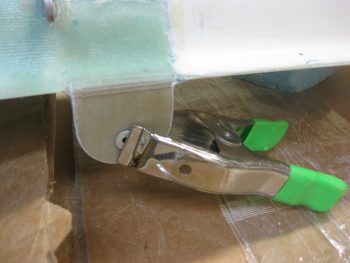
CN2 bushing floxed into alignment tab

My garage door spring snapped so I worked that issue (thanks Murphy!) for about 45 minutes before bringing the new & improved canard out to test on the fuselage.  The CN2s kicked the tops of the alignment tabs forward just a bit, but everything still lined up just fine.
Ah, CN2 creates gap...go figure!

Alignment tabs with CN2 bushings

I don’t have any action shots of drilling out the #10 holes on the canard main mount tabs to 1/4″, but here’s the end result below: AN4 1/4″ bolts in their respective holes!
Final AN4 bolt holes drilled

And at this point, I would definitely say the canard is OFFICIALLY MOUNTED!
Canard mounted with AN4 bolts!

Of course there is still much work left to be done!  I left the canard in place for a while to give the CN2s a chance to really cure in place, and then after about an hour I moved the canard off its shelf and out of the way in order to drill the 1/4″ holes out to 5/8″ using the spot face tool.
Widening canard mount holes to 5/8"

And here are the new & improved 5/8″ canard mounting holes.
Canard mount holes widened to 5/8"

And a bit closer shot of each side.

Right mounting hole widened to 5/8"Left mounting hole widened to 5/8"

I then inserted the CNL bushings into the freshly drilled 5/8″ mounting holes to mark them for trimming.
Marking CNL for cutting

I then trimmed both CNLs down on the table saw just as I did with the LWA9s for the wing to CS spar mounting, and then whipped up some wet flox & mounted them into F22.
Right CNL trimmed to size & floxed in

Left CNL trimmed to size & floxed in

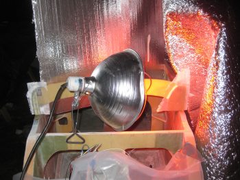
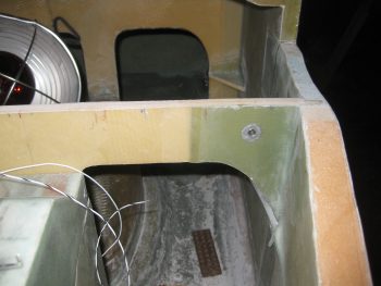
Here’s a shot of the glow coming from the heat lamp in the nose used for keeping the CNLs warm during curing.

Heatlamp on CNLs after floxed in

Here’s the same pic, only this time I used a flash.
Heatlamp on CNLs after floxed in

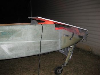
Unrelated to mounting the canard, tonight I finally go that lower cowling mounted so that I could mark up the firewall for trim.
Mocking up lower cowling with wings & FW

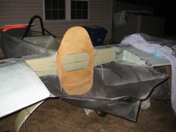
I had to lean way over into the cowling in order to mark the lower line without disturbing the taped-in-place cowling.
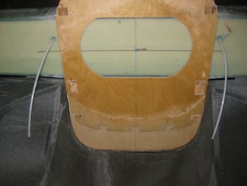
Marking firewall for trimming

I took this shot just to get an idea of what the bottom profile of the plane will look like.
Rear profile with cowling in place

Another thing that I did that is not shown in these pics is I ran a line from one wing TE corner to the other.  This let me measure from the back face of the spar to the string to determine the sweep.  I determined that I’m only 0.1″ short at the BL23 mark at the very inboard wing, and 0.4″ short on my wings’ sweep over the entire wing span: BL175.6 vs the plans BL 176.  Again, not bad and I’ll take it!

Tomorrow will be my last transmission for a few days.  I’ll be heading down south to meet up with Marco and then we’ll both fly to Rough River in his new Long-EZ.  I’ll most likely not build or post again (except maybe a quick wrap-up tomorrow) until Monday evening!

If you’re going to Rough River, SEE YOU THERE!


Chapter 12 – Mounting Canard

Today I started off clearing off the micro & finishing material from the top TE of the canard where the upper alignment tabs need to be glassed in.  I marked the spots first, for the right side, then the left . . .

Top right of canardTop left of canard

And then cleared out the finish and sanded it down in prep for 5 plies of BID.

Top right of canard clearedTop left of camard

Although I didn’t take any “before” pics, I then did the same thing for the bottom side of the canard.  The alignment tabs will get 4 plies of BID on the aft/bottom side of the canard.

Canard bottom TE cleared for tabs

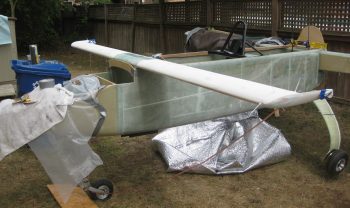
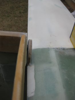
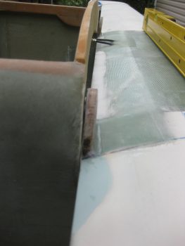
After checking the fuselage and spar to ensure all was still square, I then mounted the canard on the fuselage.  It seemed after the rain yesterday that the airplane had settled a bit, and it may have ever so slightly.  But my measurement across the aft ends of the longerons today revealed some spar-to-longeron mounting glass that was sticking up just a hair that would cause some erroneous level readings yesterday.

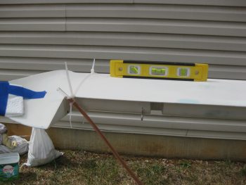
In addition, I used a very simple Side A-to-Side B water level on the canard today, as well as using levels to ensure that it is level from side to side.

Leveling canard

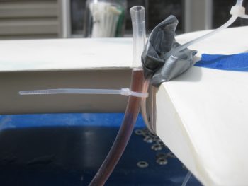
Here’s the right side water level showing it aligned with the canard TE.

Leveling canard

I still had to shim up the right side about 0.160″ to get the canard level.  A little more than my estimated 1/8″ required to offset my twisted fuselage, but I’ll live with it vs. rebuilding my fuselage!
Leveling canard with shims

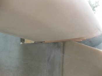
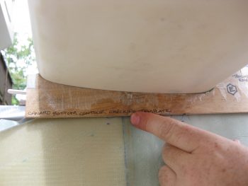
I wanted to show a pic of the gap between the canard and F22.  Today I plan on minimizing that gap by contouring the sides of the fuselage to match the bottom-side canard profile.

Gap betwixt canard & F22

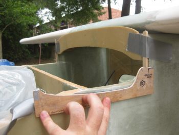
In fact, I dug out Template “E” to help me do just that.  First, I measure the normal lower profile of the canard, making a few alignment marks along the bottom edge of Template “E”.

Trimming nose sidewall

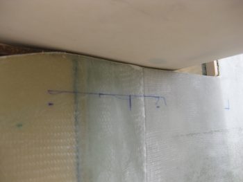
Then, I figured out how much I needed to lower the left side canard and marked those lines below the bottom edge line of Template “E”.

Trimming nose sidewall

I then moved the canard off the F22 “shelf” so that I could have access to sand out the bottom F22 profile.  This happened at least 20 times today, trial and error being the order of the day!
Is this mounted right?! ;)

With the lower marks in place, I simply matched the lower straight edge of Template “E” to the lower marks and then marked along the top edge of it which gave me the correct contour I needed for the bottom of the canard.

Profile for trimming sidewall

Profile for trimming sidewall

I then sanded down a significant portion of the area above the profile line above, and then kept checking for the high points (as shown below)… marked those and proceeded to sand them… with prejudice!  Again, this process was repeated countless times!

Sanding down sidewall for canard

Here’s a shot of the fuselage sidewall cutouts.  Notice the left is much deeper than the right sidewall.  Which accounts for my lopsided fuselage (ahhh, the sins of the past….).

Profiling sidewalls for canard

Here’s a couple more shots with the canard in place, from below.

Profiling right sidewall for canardProfiling left sidewall for canard

As I did hundreds of times today, I then rechecked the level on the top of the canard.  I was having a devil of a time getting the canard to stay level whenever I tweaked the incidence.  Of course the Roncz canard mounts with the lower tabs at an angle (unlike the GU canard), so keeping the bottom tabs tight wasn’t allowing me to get the canard Leading Edge (LE) nose up for the proper incidence.  The whole herding cats thing was in full swing here, so I decided to minimize my variables and work with the known quantities I had on hand.

So far so good!

To keep the lower mounting tabs clamped, but then still be able to dial in my incidence by getting the canard TE down –thus, in essence the LE up– I decided to use my upper alignment tabs to do just that, align the canard!  So with some trial & error, and the main mounting tabs secured with clamps, I was able to use the height of the upper alignment tabs to dial in the correct incidence WHILE at the same time keeping correct sweep and level.

Of course this is NOT the order that the plans have you do all this, since in the plans you drill a #10 pilot hole through the lower tabs first, then mount the upper alignment tabs later. But the original plans are dealing with a straight-flat-bottomed GU canard that required no contouring of the fuselage sides.  I tried to prognosticate any future issues by doing it this way, and I couldn’t think of anything that would come back to bite me, so I proceeded to drill, trim & mount the Birch plywood (vs foam) for the upper canard alignment tabs.

Top alignment tabs in place

That kept the canard sweep & the level dialed in.  But I of course re-checked both to ensure all was good!

Still good . . .

Continuing on with my working the known variables theme, I went ahead and glassed the front mating face of F28 to dial in my sweep with the newly mounted upper alignment tabs. I figure I’d work the canard install elements in the same way they are presented in Chapter 12 of the plans: SWEEP ⇒ LEVEL ⇒ INCIDENCE.

It may be a bit difficult to see in the pic below, but I then cut wedges in the foam sidewall uprights that are adjacent to F28.

Foam flox corners prepped

I then filled these foam wedges with flocro just prior to laying up 12 plies of BID on the left side (remember, I need to bring this side face out 0.155″) and then laid up one ply BID on the right side.  I was going to only layup 11 plies of BID on the left side, but went ahead and added one more so that I could the glass the right side with 1 ply of BID as well.

Flocro added to foam uprights

I had already wetted the 12 plies (in 4 sets 3 plies) of BID out before filling in the foam with flocro, so when I got back into the shop I merely squeegeed out the excess epoxy.

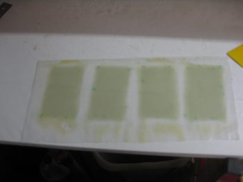
3 plies x 4 BID pads = 12 plies

I then cut each set of the 3 plies of BID in prep for layup.

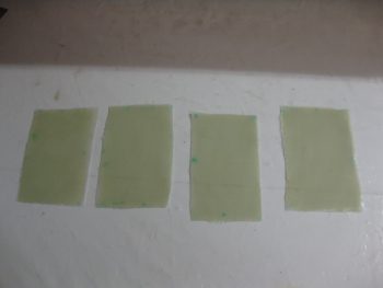
3 plies x 4 BID pads = 12 plies

Here’s a shot of the heat lamp on the 12 ply BID layup.  Let’s just say that it cured fairly quickly!

12 plies laid up left side, 1 ply right

With the F28 bulkhead spacers in place, I then set my sights on glassing the front side of the upper alignment tabs with 5 plies of BID each.  I do have to state that my 5 min glue must be old because it was still a bit rubbery even after about 25 min.  I’m only going to layup the front side BID so that if need be I can heat up the tabs and move them forward or aft.  Not an optimal way of doing this most likely, but I really saw no other way of dialing in the incidence without spending an enormous amount of time making wedges for the lower mounting tabs…which just didn’t seem nearly as efficient as doing it this way.

Upper tabs 5-min glued in place

I sanded away the gummy 5 min epoxy on both tabs…

Left tab prepped for glass

Right tab prepped for glass

Then wetted out 2 sets of 3-ply BID and 2 sets of 2-ply BID to give me a total of 5 plies for the layups for both the left & right tabs.

2 sets: 3+2 = 5 plies BID

I then laid up the forward tab faces with 5 plies of BID, after troweling in some dry flox fillets in the mating corners.  I then peel plied the lower, horizontal part of the layup for a smooth transition into the canard top surface.

Left & Right upper tabs glassed

After a couple of hours, I then razor trimmed the upper tab glass.

Left & Right upper tabs razor trimmed

Here’s a shot of the left upper tab after I razor trimmed it.

Left upper tab razor trimmed

I did do one thing today not canard related: I used my Fein saw to remove the CS118 plate in the back seat in prep for moving the control stick mount just a hair inboard!

Removng CS118 for replacement

Tomorrow I plan on moving out as much as possible to get the canard mounted to the fuselage.

Much to do before Rough River!