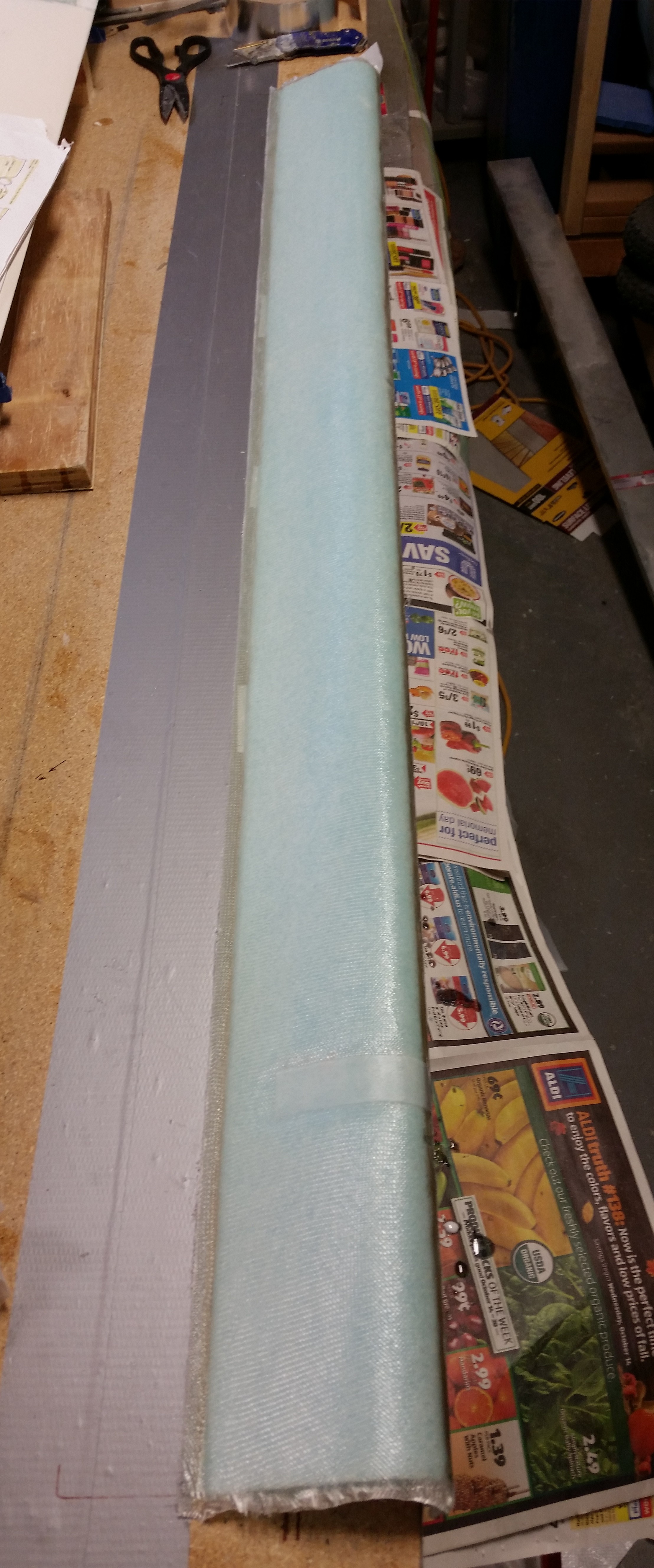
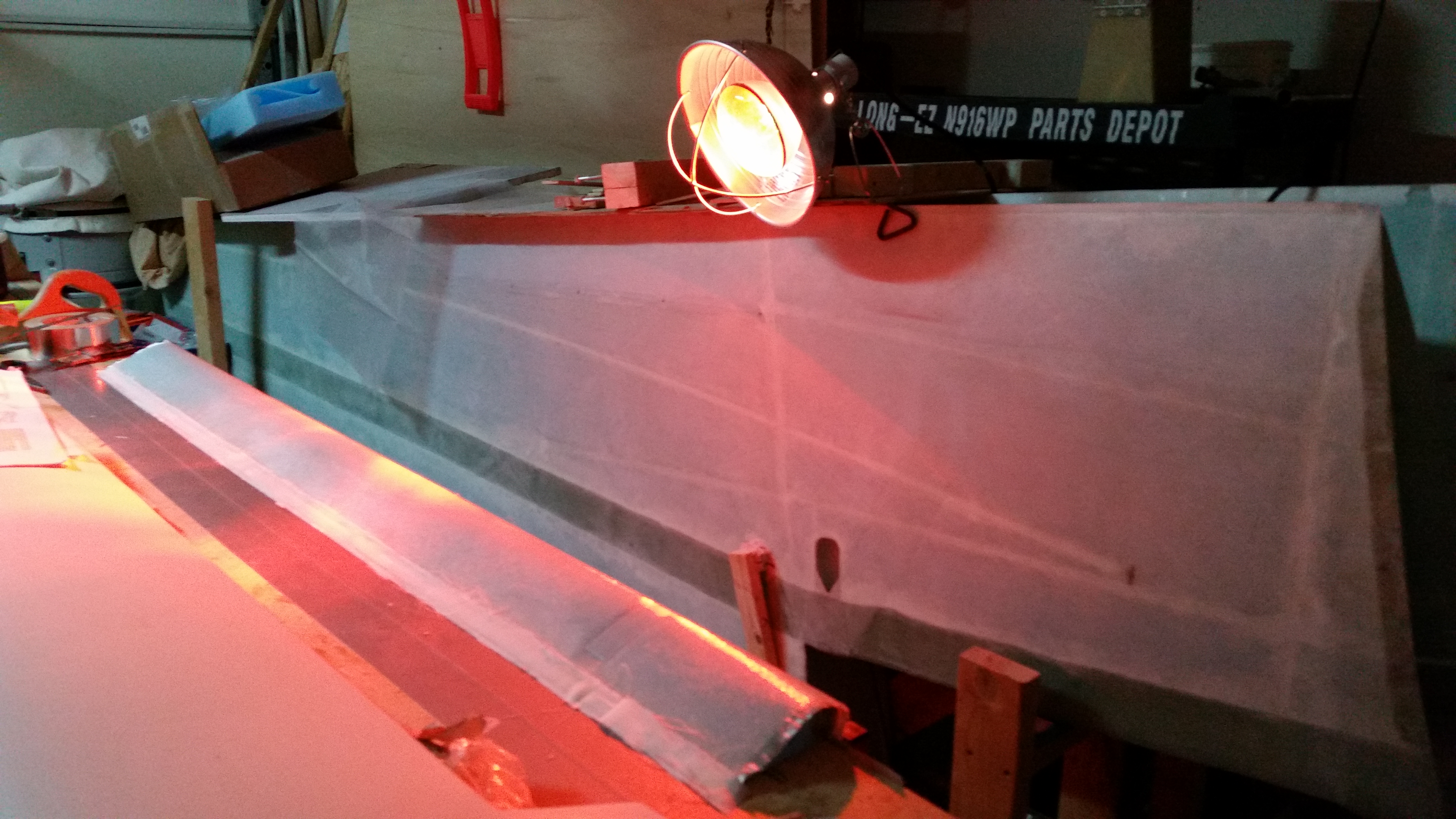
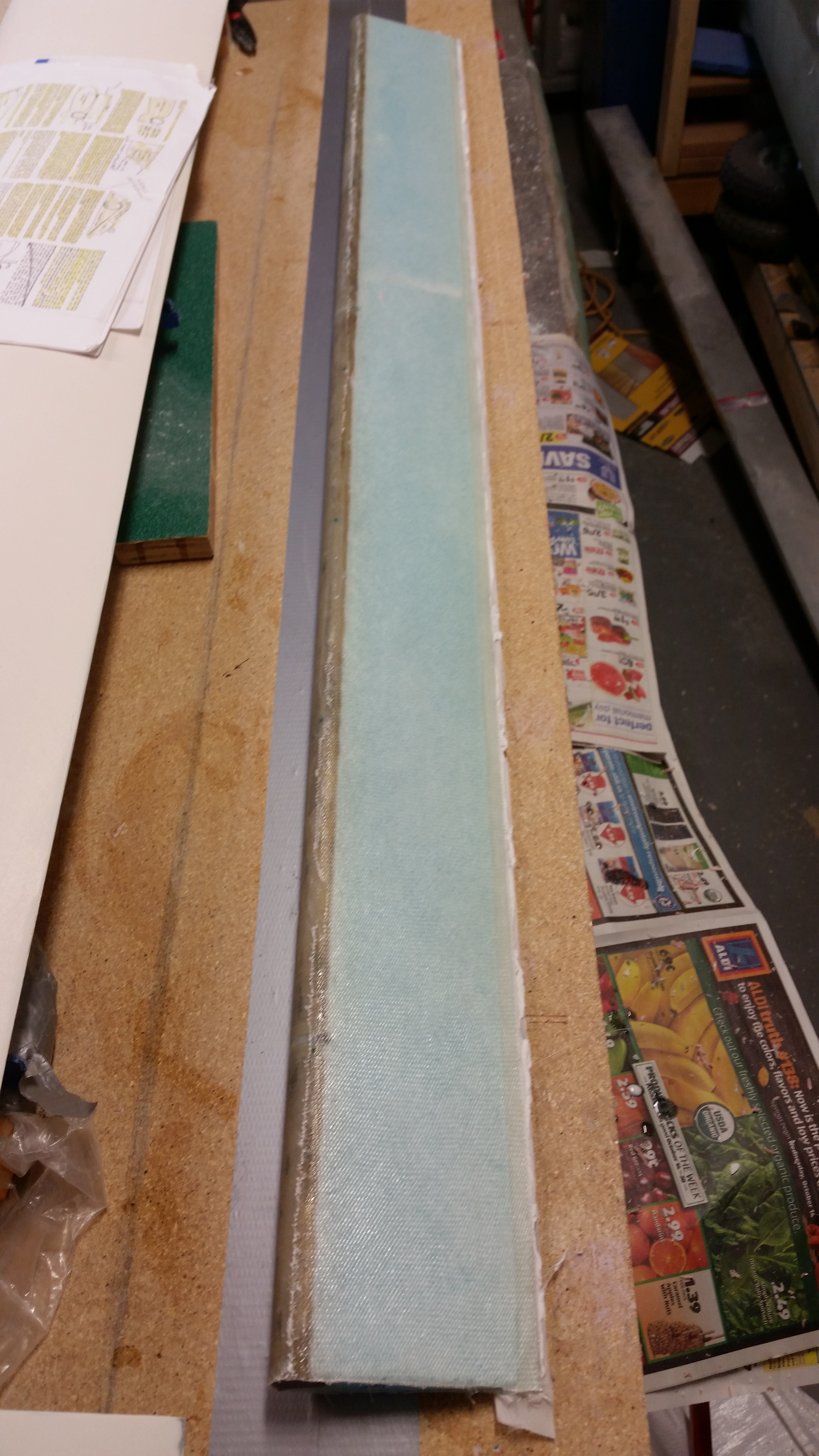
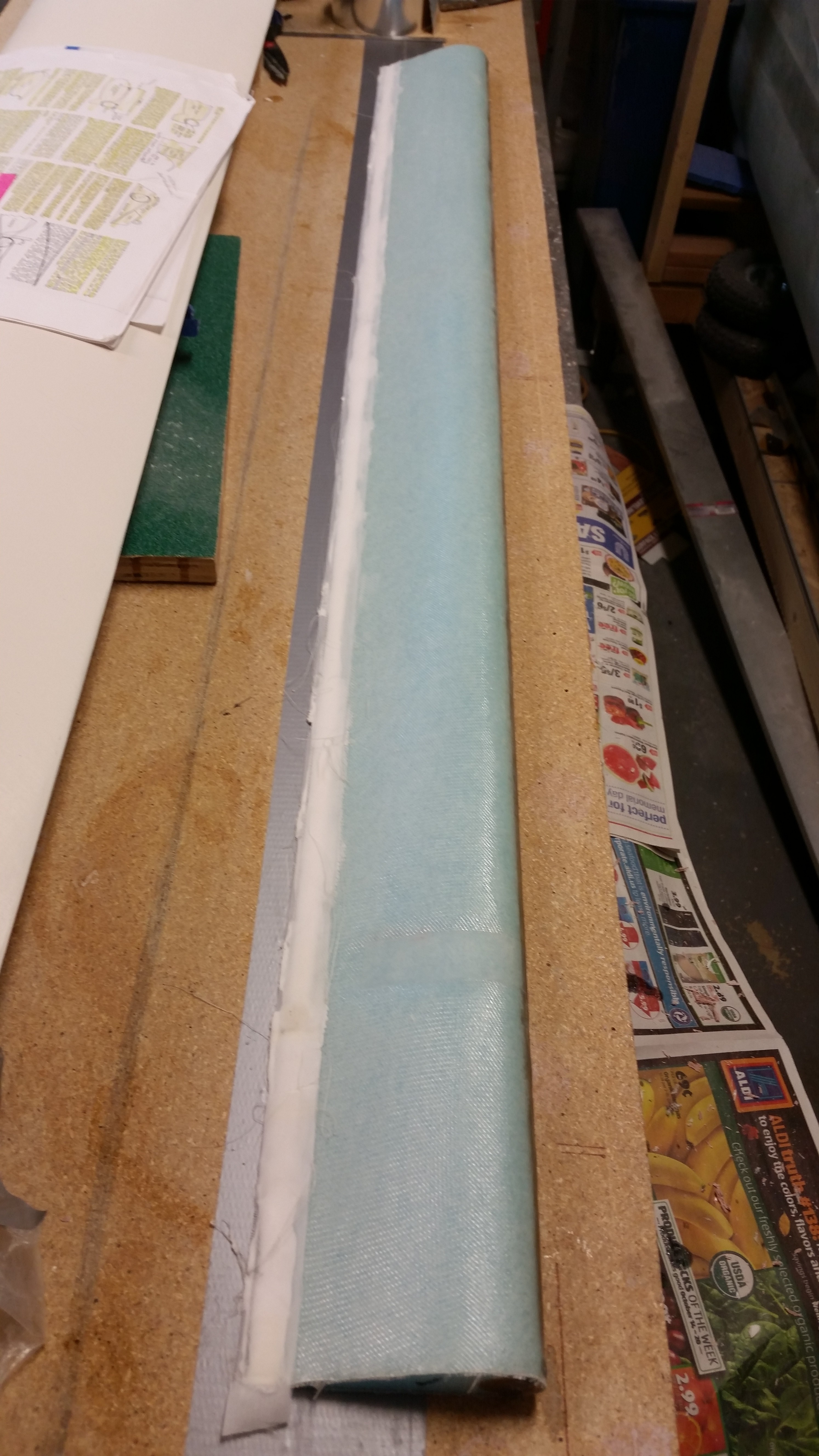
Chapter 22 – More electrons

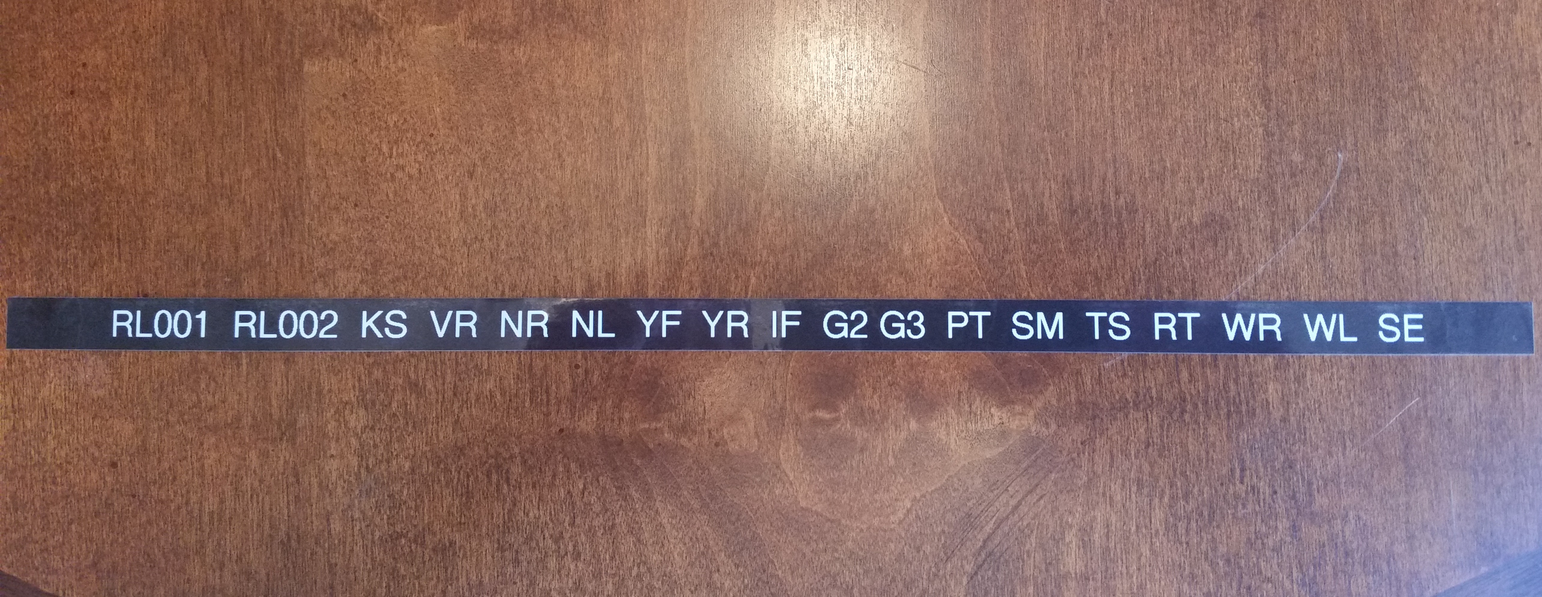
Today was another bust on getting some shop work in.  Between business calls, meetings and knocking out some personal errands, I just couldn’t get some shop time in.  One thing I could do while I was on the phone was make labels for my electrical components.  So I did.

As many of you may know I designed my electrical system so that I have each component identified with a 2-digit code, and then a 3-digit identifier for the pin, wire  or connector.  Combine this with a 1-letter designator prefix that identifies one of 12 distinct areas of the aircraft, and I then have a resulting 6 digit code that tells me exactly where any wire is coming from or going to, and the device at each end.

So as I was on the phone I simply pulled out the label maker and started going through the list of codes.

Electrical component labels

When I got a chance I would cut a few out and label the components that I have close by.  Since I was in a groove at the end of the work day, I simply rolled into digging into my stores of electrical stuff and labeling a large number of them.  I would say I have about 70% of my electrical components on hand labeled.

Since I was deconflicting and updating my electrical component ID list, this segued into my figuring out more finitely each component installation location in the airplane. I pulled out the Electrical Book of All Knowledge, The AeroElectric Connection by Bob Nuckolls, and reviewed it to make sure I was not straying off the straight & narrow path of good electrical practices.  Especially considering that plastic airplanes amplify a lot of commonplace negative issues that crop up in wiring any airplane.

I also reviewed a lot of other builders’ electrical systems, analyzed those, and emulated a lot of good install how-to’s.  I also jotted down some crude diagrams to look at wiring runs, device locations, etc.  This involved digging out a lot install manuals and verifying a fair bit of information.

By working through what I did last night, I really feel that I confirmed and elevated the completion level of my electrical system design from about 75% to about 90%, and with just a few more minor pieces of information, and perhaps a few phone calls, I’ll be really close to locking in the final locations of nearly all my electrical components.


Chapter 22 – It’s Electric . . .

Today I didn’t get any shop work completed.  I had planned on organizing & cleaning the shop a bit, and then getting the fuselage mounted on the dolly, but ended up working on the electrical system for about a total of 6 hours.

Although I didn’t add it to my log entry, I had actually spent a couple of hours Saturday diagraming out the circuit for my canopy & gear warning module.  I thought I was looking for a DPDT microswitch to match the one Jack had mounted on one side of the gear actuator housing for the down limiter.  The other side only has a single switch.  I even sent Jack an email asking for the part number, since all the info for the microswitches were hidden from me on account of how they were mounted with the nomenclature, etc. facing the mounting flange.  I didn’t want to move these suckers unless absolutely necessary since they’re “factory” set initially for the correct up & down limits.

Well, right before I left the house for the evening I took a much closer look to see what type of roller the microswitch had and the length of the lever arm.  Upon closer inspection I realize it had two rollers??  Wait a minute!  This wasn’t one switch!  It was two switches stacked one over the other!  Doh!  I remembered I had a microswitch included in my accessories for the speed brake, which I also bought from Jack.  I pulled that switch out, saw that it was the same switch as those mounted on the nose gear actuator, and so was able to get the manufacturer and part number off of that one. I then quickly sent Jack an email saying that I apparently need glasses and to disregard previous transmission!  All of this hassle for a $3 switch!  BTW, the switch is an Omron SS-10GL2T.

With the switch issue settled yesterday, and with the added wiring the new switch circuit will add, I was armed with the info I needed to order a new 14-pin AMP CPC connector from Mouser.  I assembled my order which included a whole lot more pins & sockets, a pin/socket removal tool and of course the Omron microswitches.

I then turned my sights on a developing order that I had with Aircraft Spruce.  I’ve been assembling this order over the past couple of weeks and wanted to get to a point where I felt I wasn’t missing anything important, like the quart of fast MGS hardener and 1″ peel ply tape that I added just prior to hitting the “submit order” button.  The order includes a lot of odd n’ end fasteners & hardware for mounting electrical components, etc. in the nose.  Of course, as luck would have it (as it always does!), a few hours after submitting the order I ran across EZ Point studs on Joe Carragio’s website while doing some research.  They’re a bit pricey, but I know of a few places where I definitely want to incorporate these. Thanks Joe, I’ll add them to the list!

I then spent a few hours on virtually organizing the components of my electrical system. Yes, in true neanderthal fashion I pulled them all out, traced their profile on a sheet of graph paper, and then identified which bus they were wired to, and looked at the length & destinations of the wire runs.  Again, since so much of this business occurs in the nose, and that’s what I’ll be building next, I don’t mind taking a few hours to get better educated on just what the nose will house before I start building it.

I made a number of annotations and tweaked/swapped/modified a number of other circuit connections simple based on location of component and the ease/requirement of access. The bottom line is that I want the guts of my electrical system to be as optimized, organized, clean, and lightweight as possible.  I don’t want a rats nest of wires that looks like the cable monster puked in the nose of my airplane and then merely shut the lid to hide the hideousness of it all!

In addition to the aesthetics of the system, I want my electrical wiring to be practical in that the configuration of it all minimizes head-scratching during future troubleshooting or component additions, and even more importantly that the RF noise is mitigated to the maximum extent possible.

After creating a ton more notes, and figuring out some important electrical system design info and component placement, my final official act of the evening was deciding that a 14-gang fuse holder would be the right size for my E-Bus.  Thus, I pulled the trigger on that as well and ordered one.

So although I have no sexy build pictures to post, I did get a ton of stuff sorted through and a lot accomplished.  And I got three separate orders in on various in-depth, technical stuff I need for this build.  Not a bad day for the build I would say.


Chapter 11 – Elevator redo done!

For the right elevator at least.

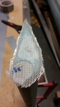
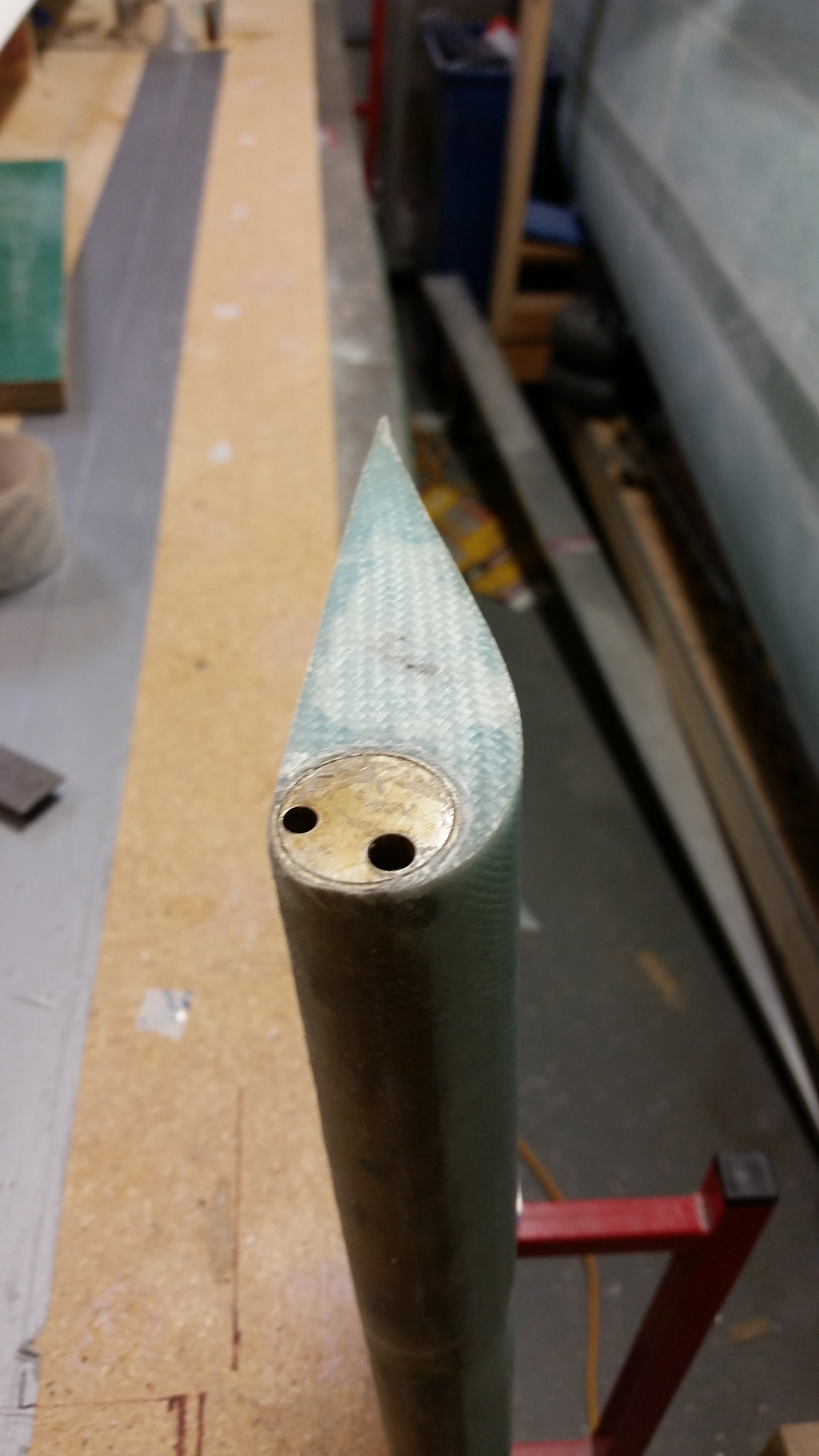
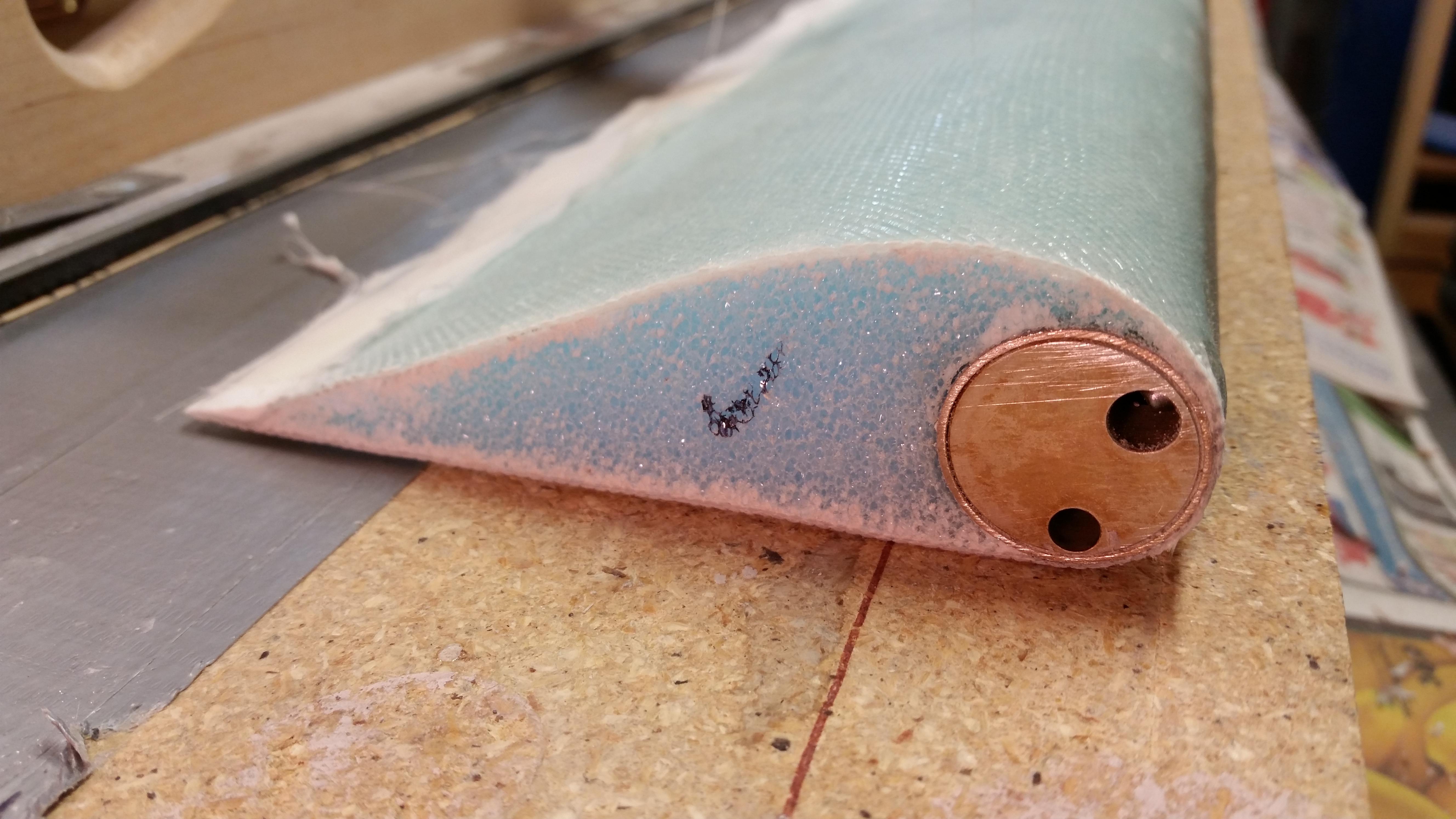
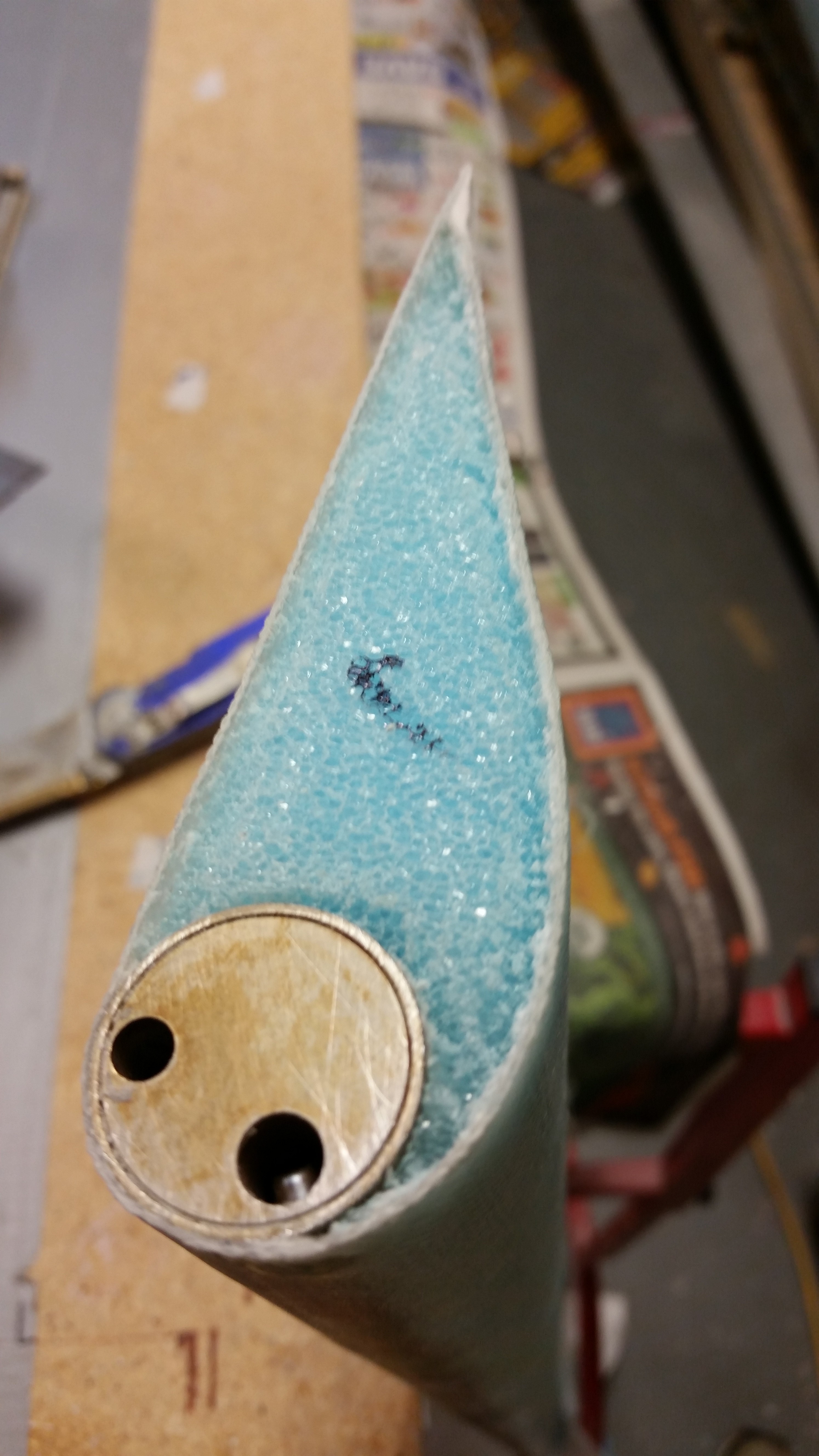
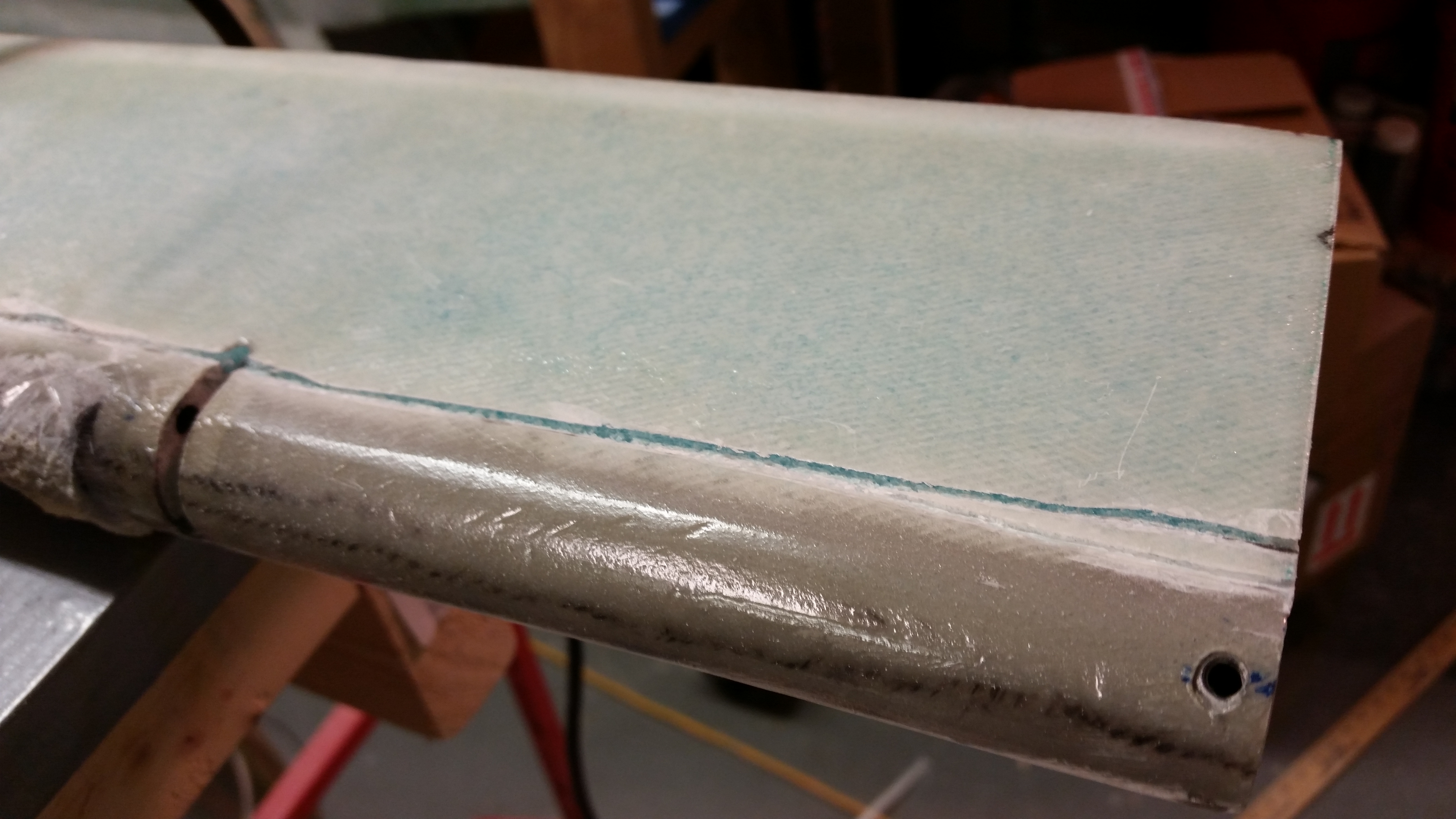
I started off today by trimming the elevator 1-ply BID glass that I laid up last night.  I never made it back down to razor trim, so thank goodness it’s only one ply.  I then sanded the edges flush with the surrounding top & bottom skins.  I also had to cut out the glass over the NC-6 insert, and while doing so thought I should have stepped out of my paradigm and just glassed over all of it.  Oh, well, a few more minutes and I had what you see below.

Outboard elevator end

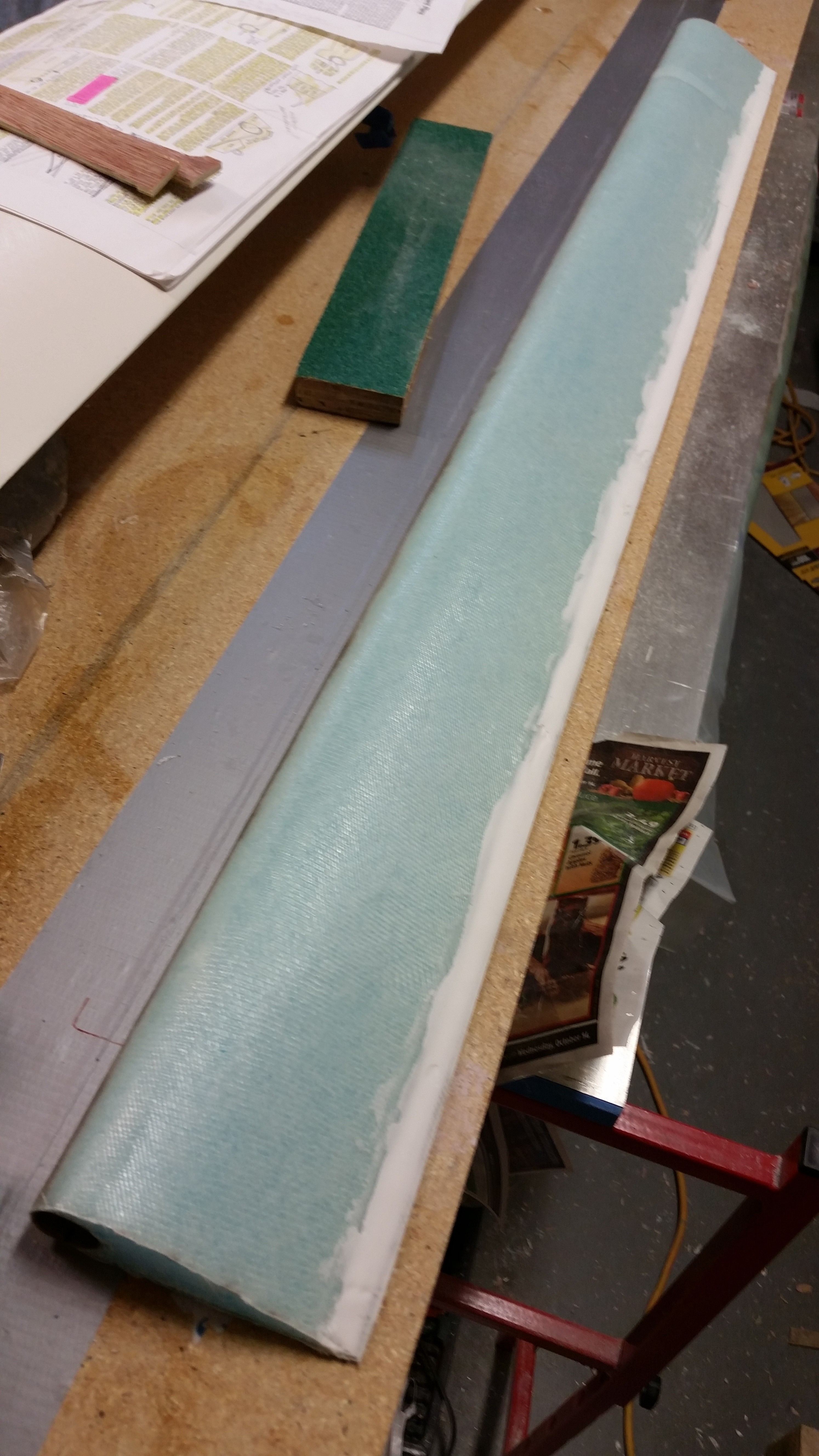
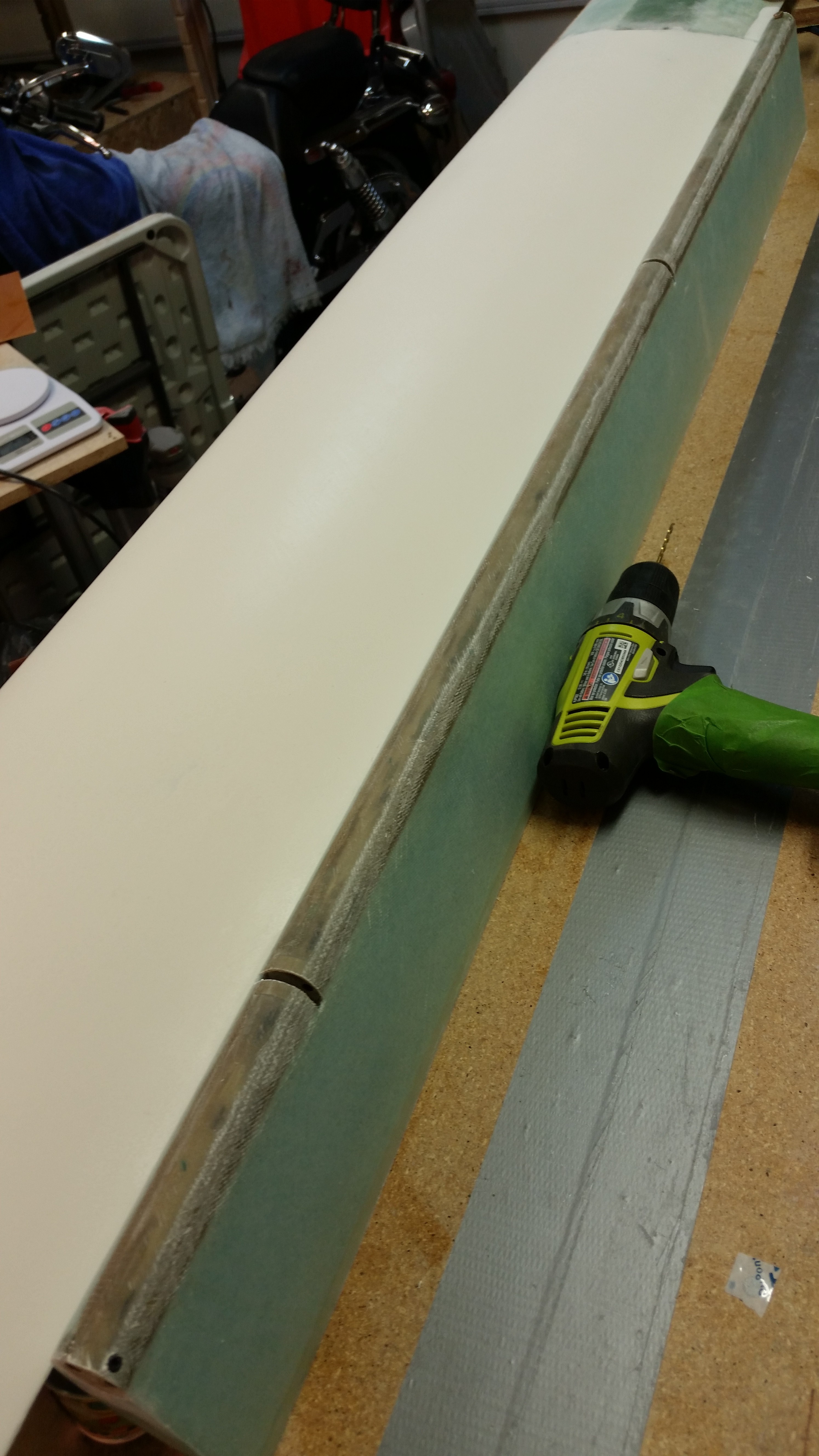
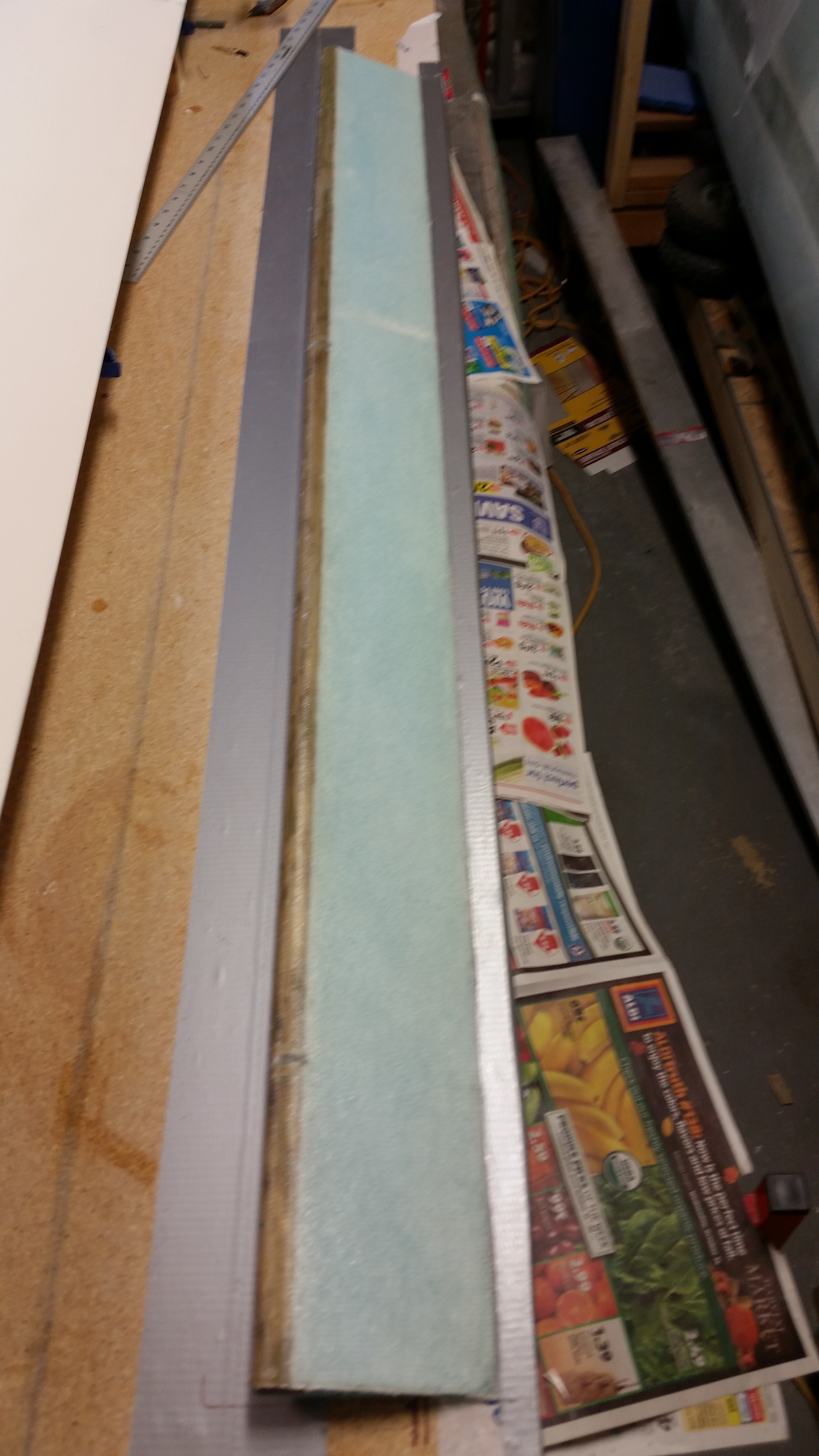
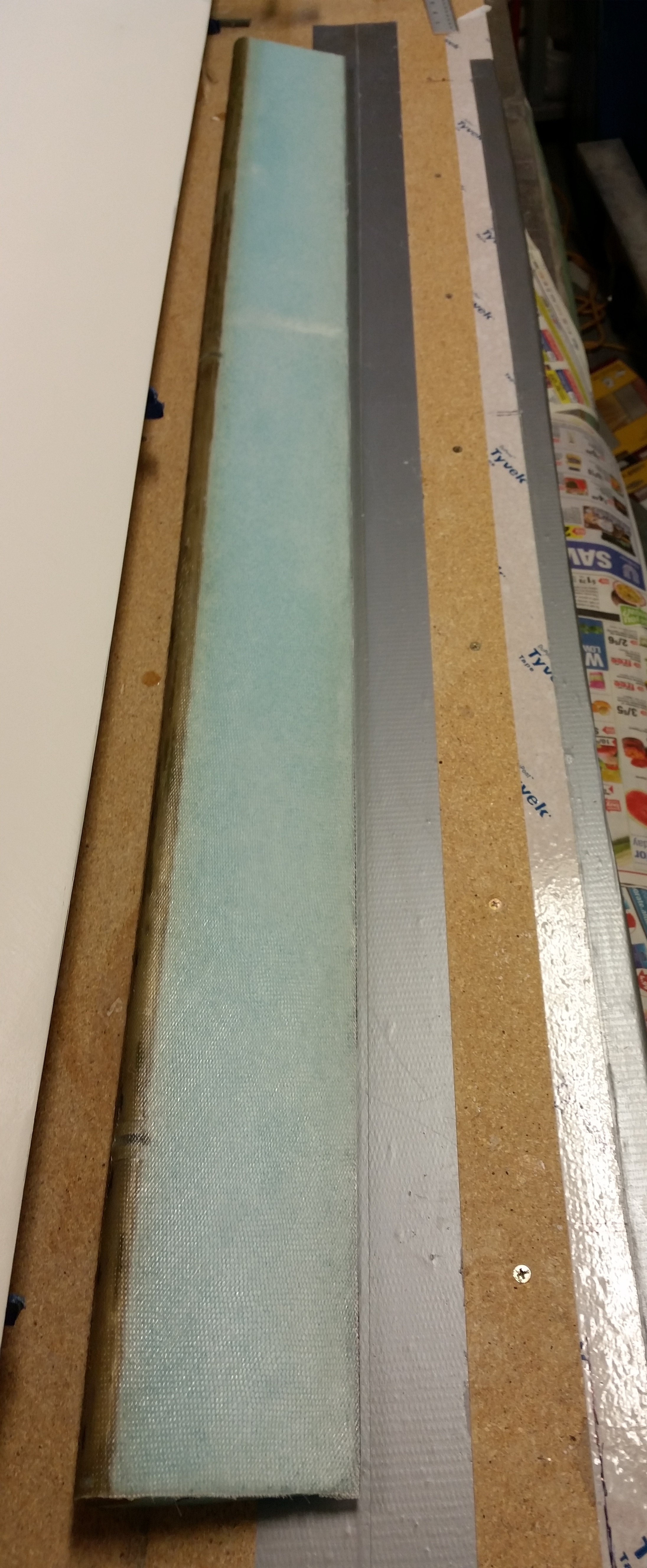
I then turned my sights first on sanding the rough spots of the LE, and I then pulled the peel ply and sanded the TE.

Sanded TE

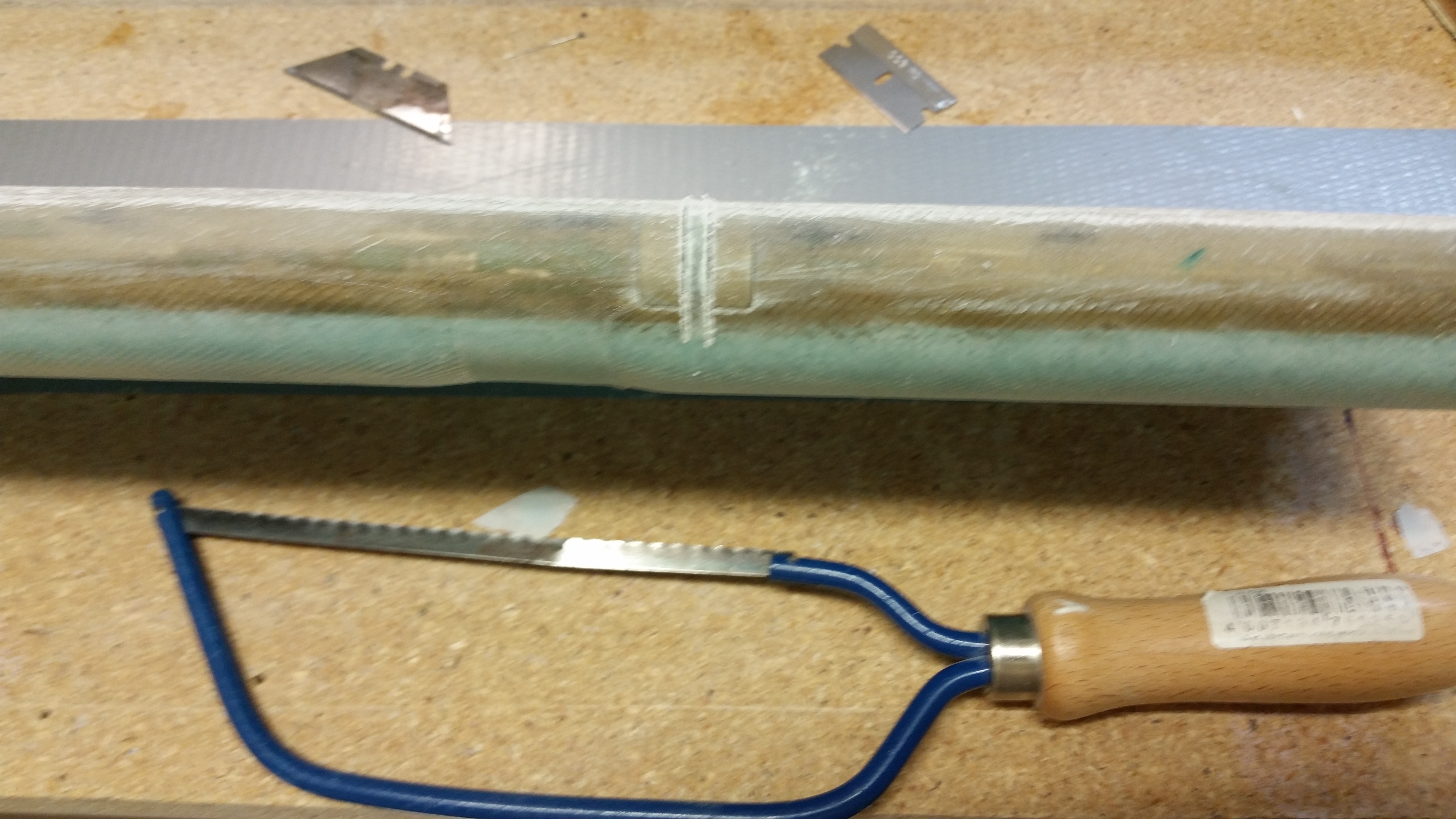
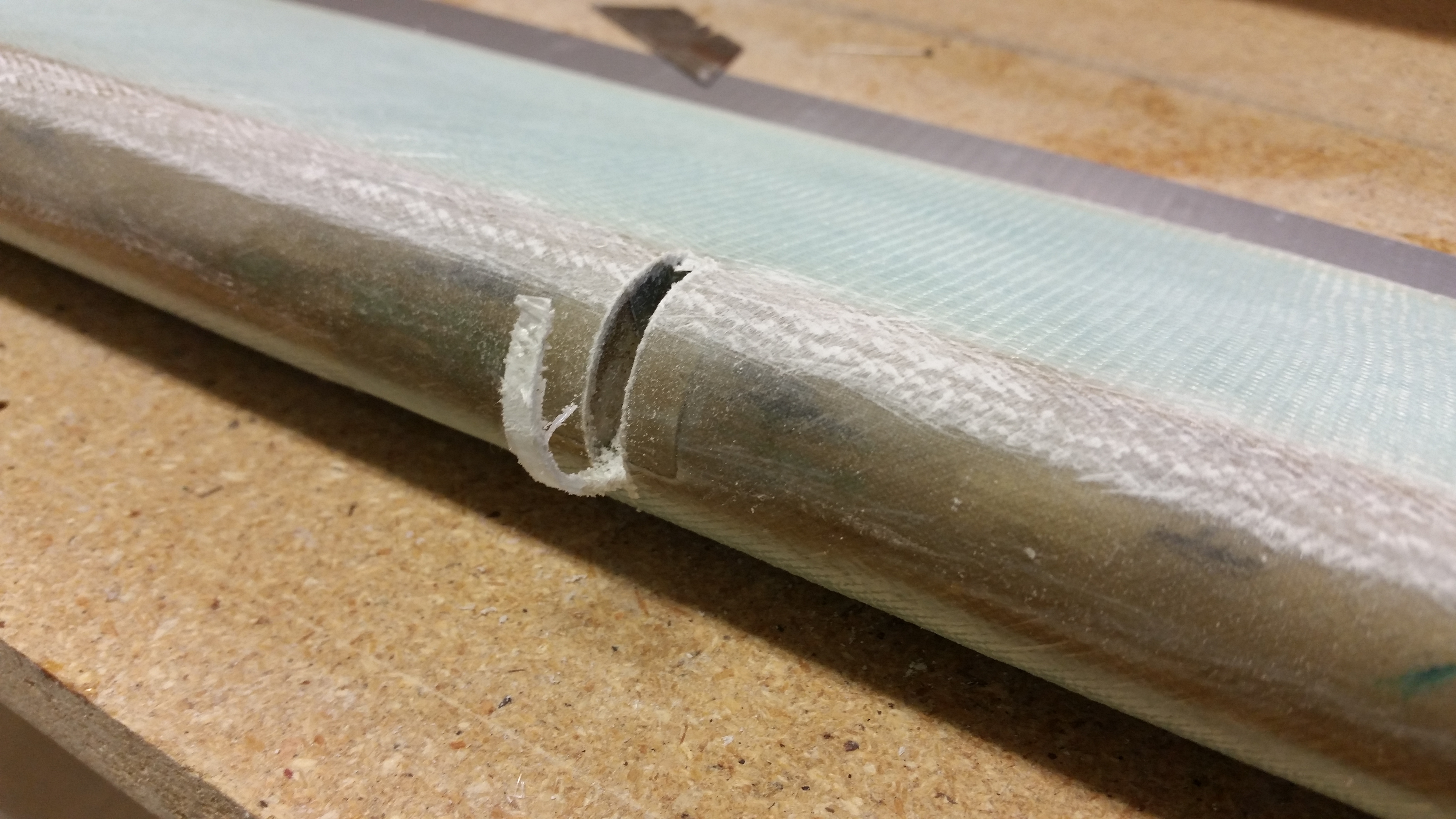
I took my German Praktiker special hand saw and cut the channels for the hinges.  After the major cut, I cleaned up the channels with a razor blade and removed the duct tape over the hinge pin holes.

Cutting hinge channelsCutting hinge channels

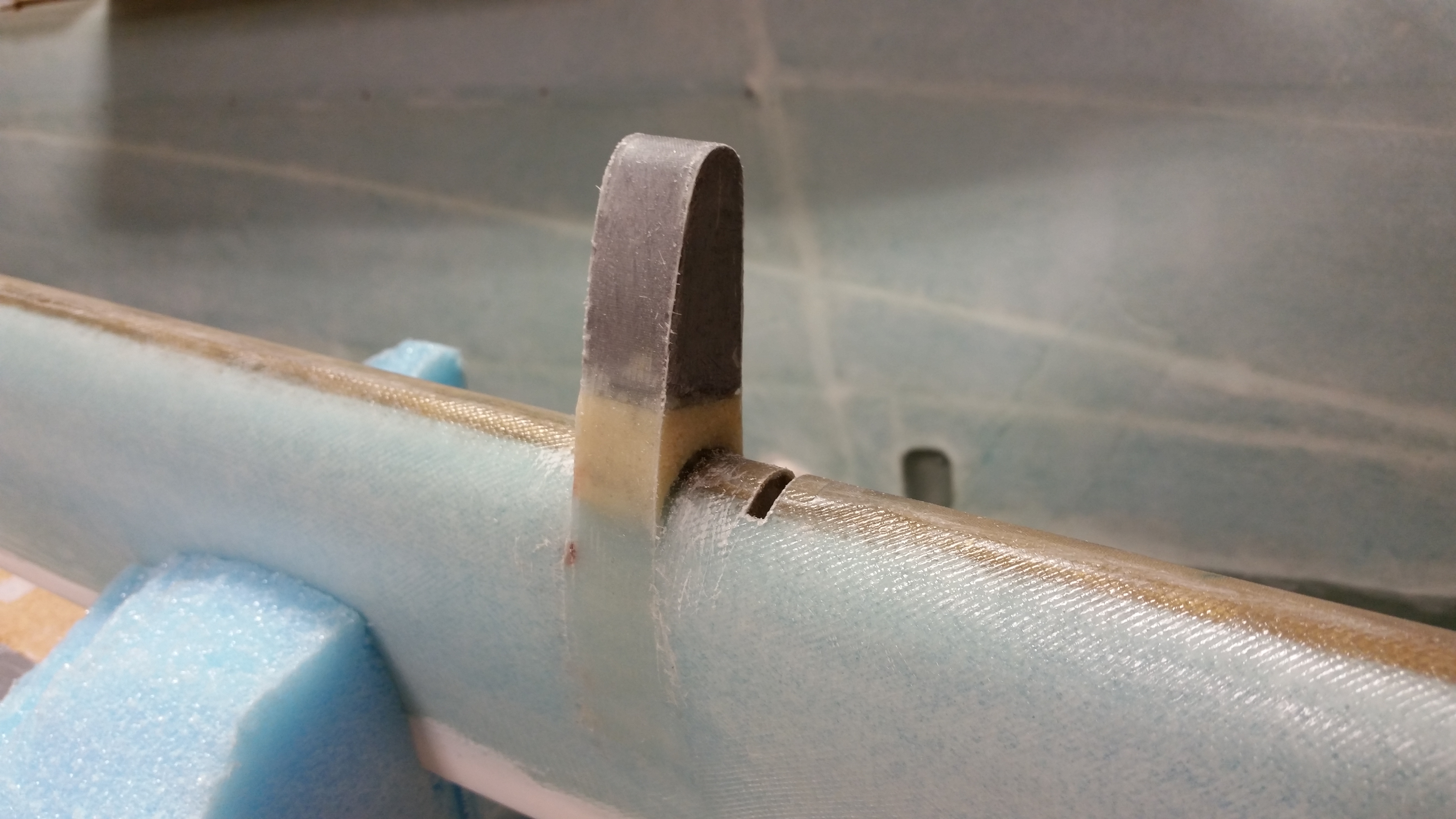
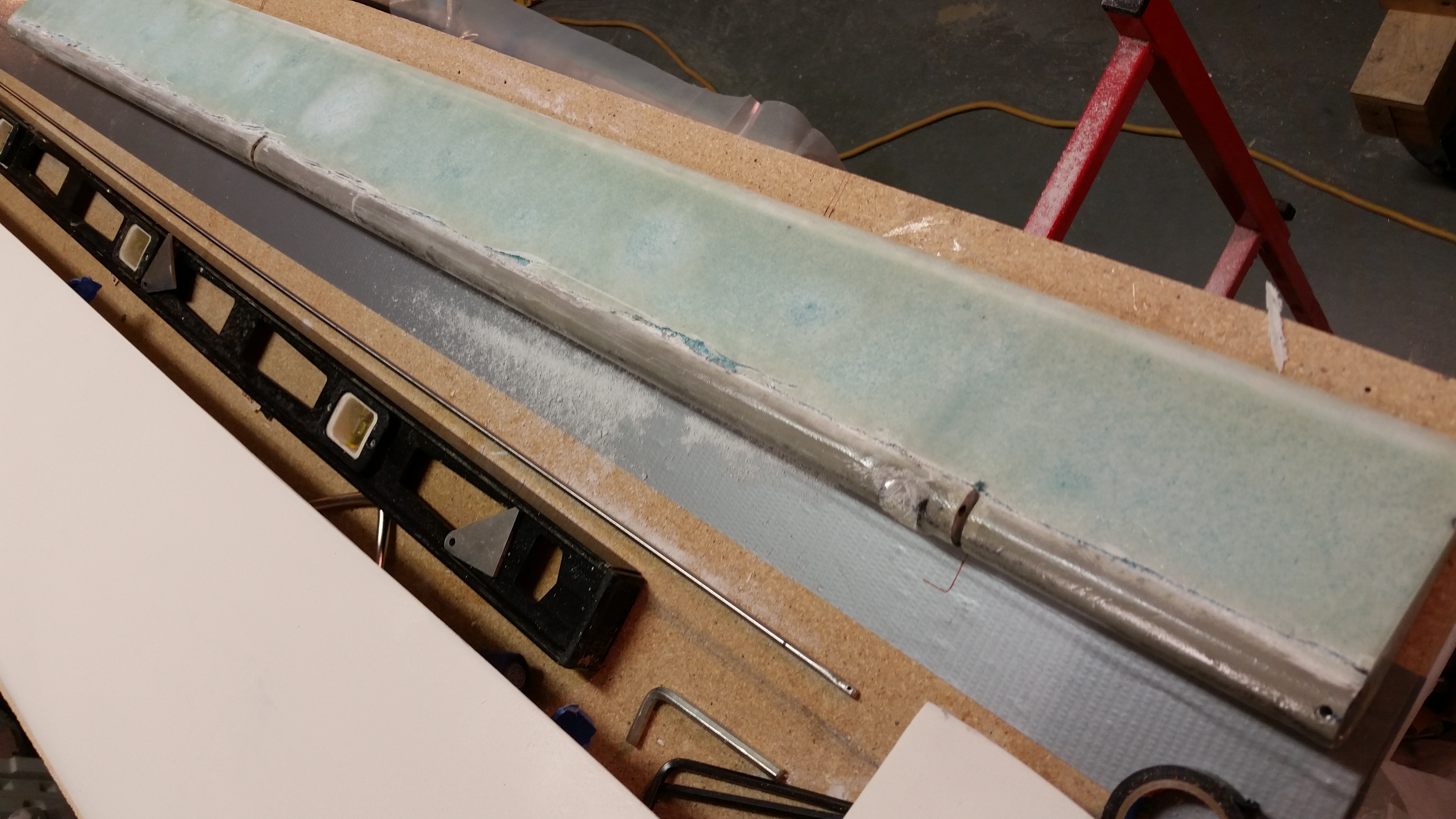
Below is a shot of the ancillary clean up, including the two hinge channels, the set screw hole at the close end and the torque office attach bolt hole at the opposite end.

Bits 'n pieces complete

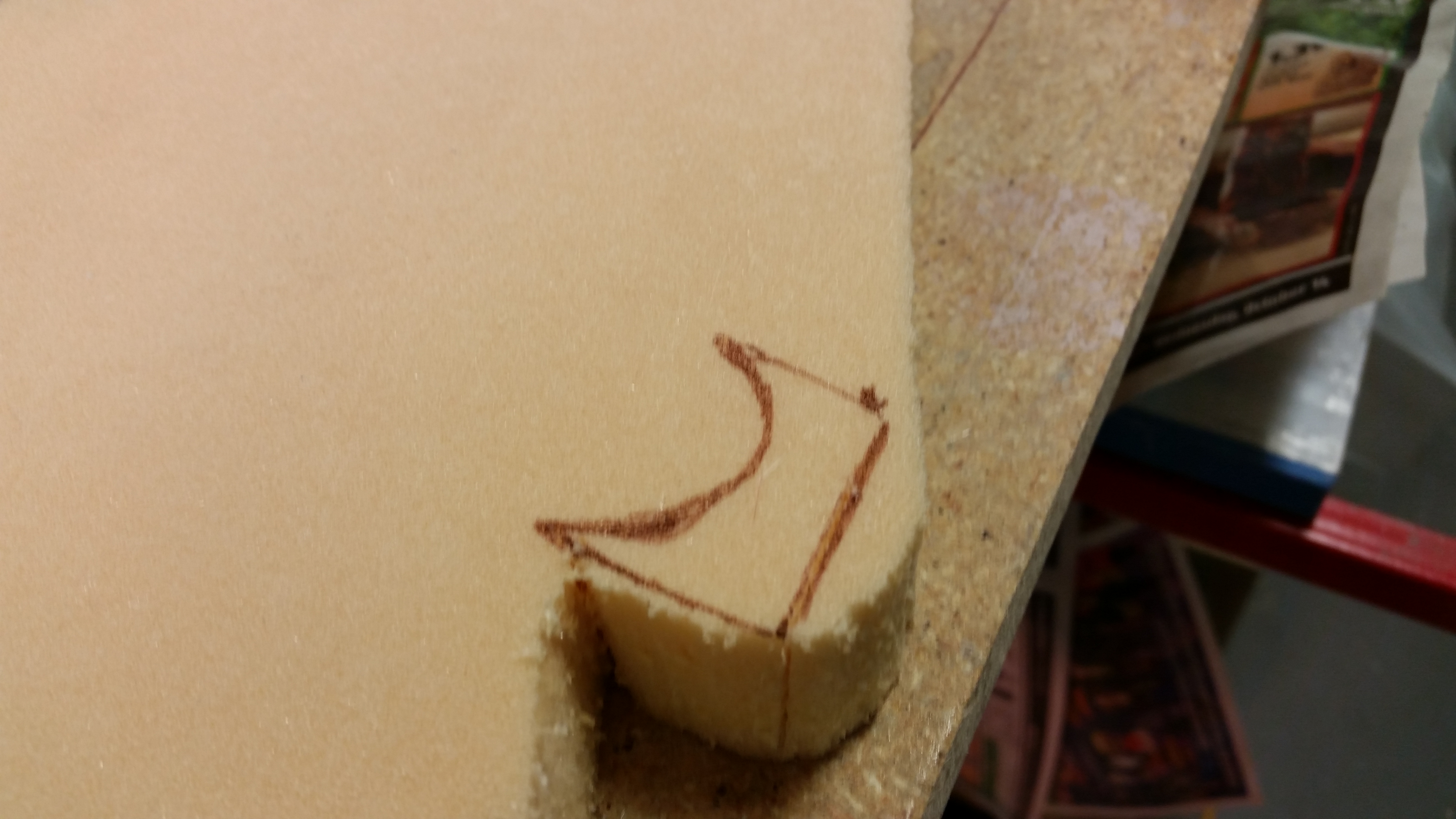
With the elevator pretty much completed, I turned my sights on the outboard elevator weight.  I marked up a new foam spacer on the H100 foam piece I have on hand. I then cut it out and shaped it with 36 grit sandpaper.

Outboard weight H100 spacer foam

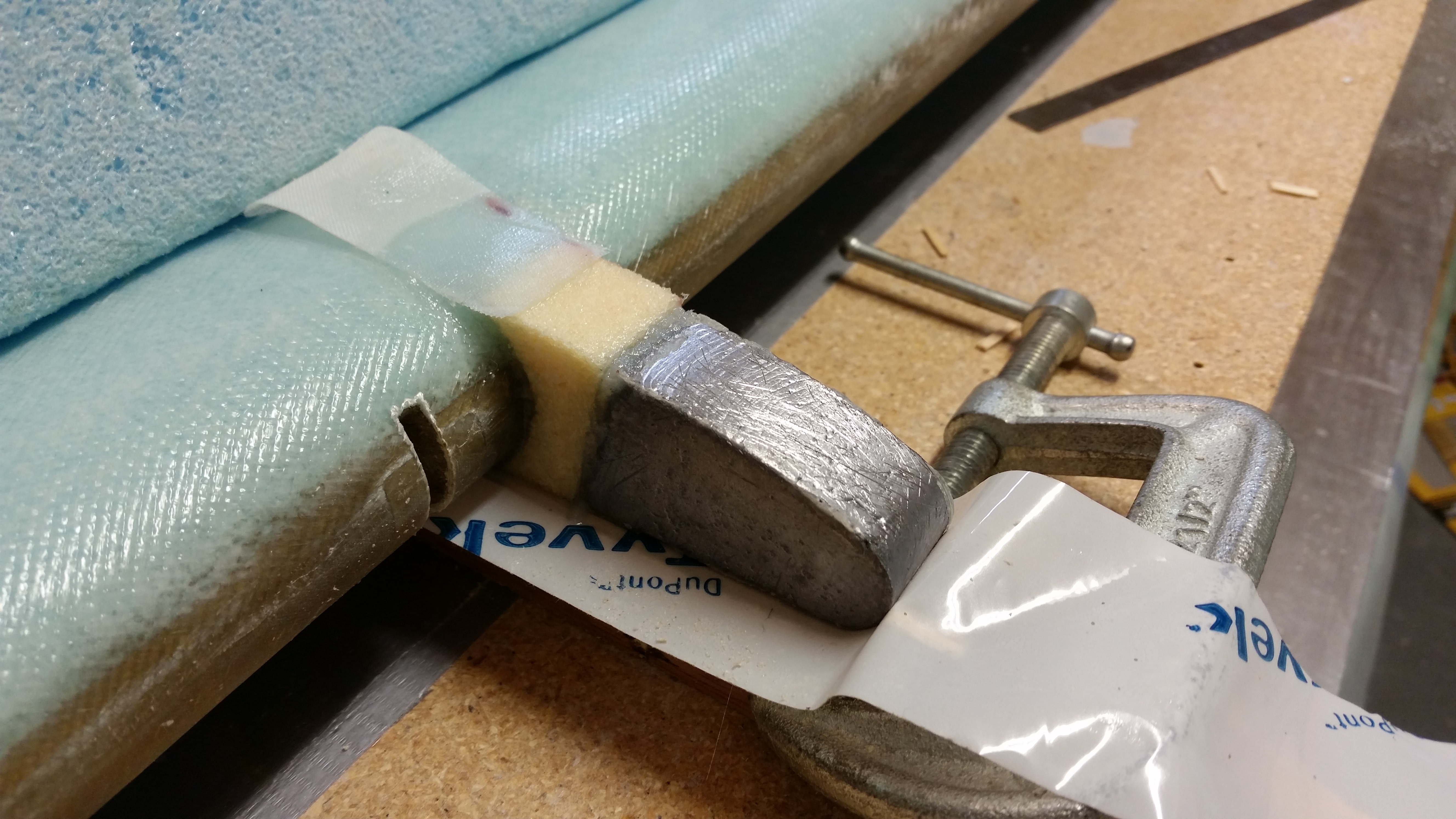
I worked for about 10-15 minutes to get the foam spacer shaped properly, and then floxed the weight & foam spacer in place using the templates.   Now, interestingly enough the plans say that you can use 5-minute glue, but of course I didn’t think of this until I had a batch of flox mixed up and of course I just bought some last week.

Oh, well, I just had to wait a little bit longer to glass it with 2 plies of UNI.

Outboard elevator weight floxed

A few hours later I cut out 2 strips of UNI and laid them up around the outboard elevator weight as per plans.  I then peel plied the layup before heading out for the evening.

Outboard elevator weight glassed

When I returned everything looked good & cured.  I pulled the peel ply, razor cut the glass, and then hit the edges very briefly with sandpaper.  Here’s the end result.

Outboard elevator weight cured

And with that folks, I’m calling the right elevator rebuild complete!


Chapter 11 & 13 – Glassing elevator

Here’s a shot of the trimmed elevator as it looked when I started working on it today.
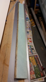
Cured & trimmed bottom elevator skin

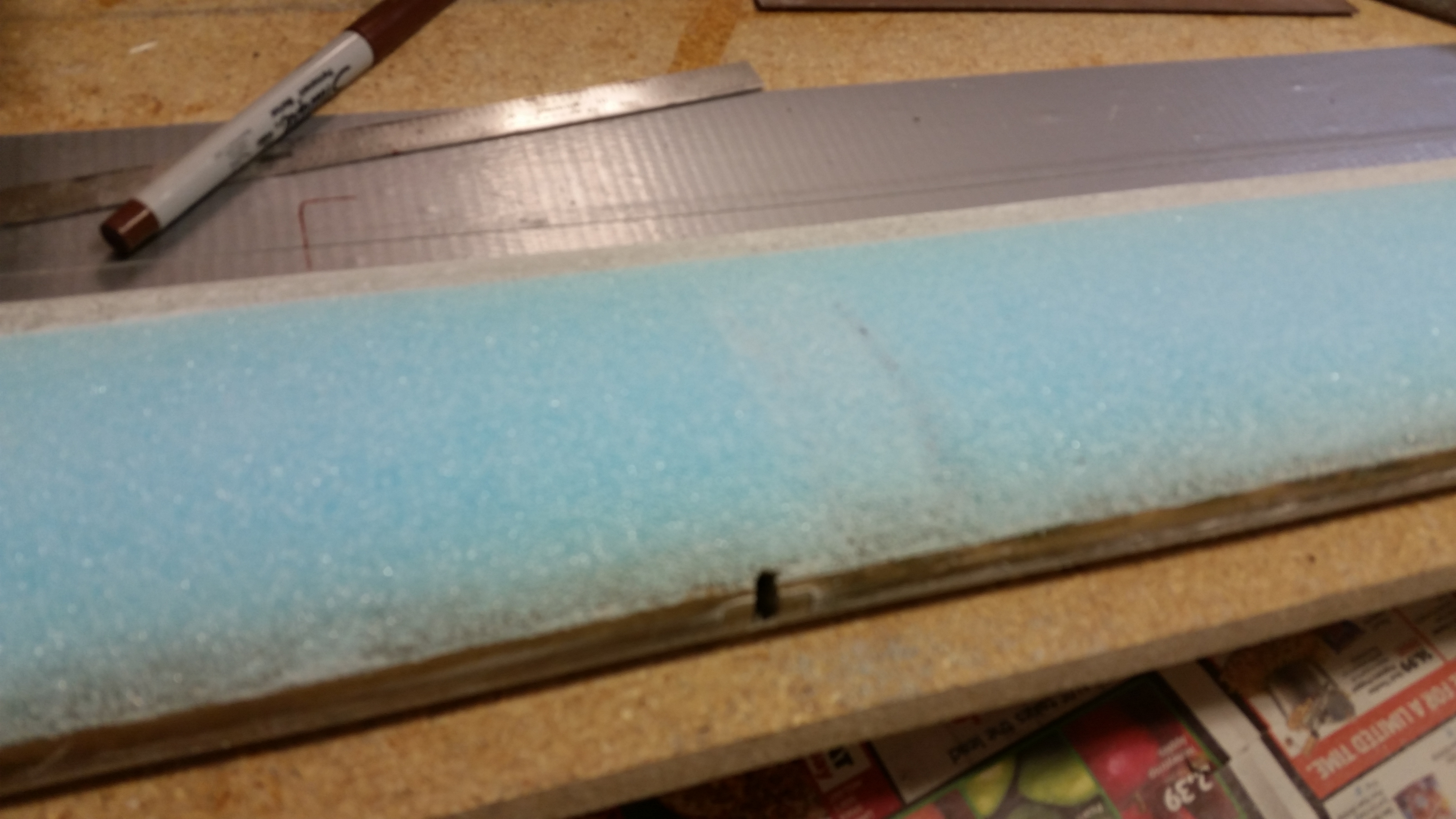
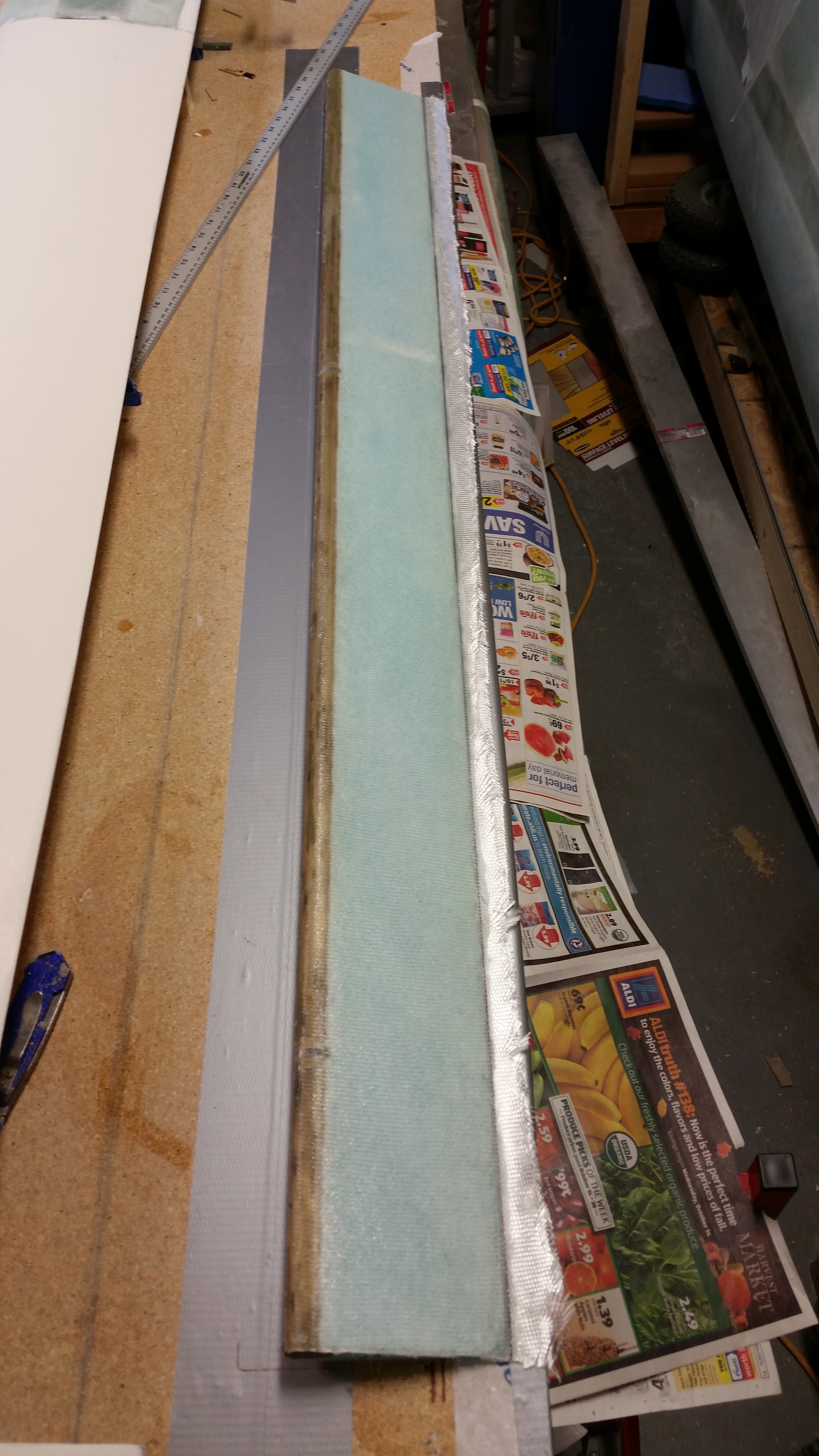
I pulled the elevator off the workbench and was happy that by using the foil tape I had NO divots on the top of my elevator foam.  In addition, you’ll note the blobs of 5 minute glue on the table.
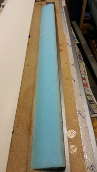
5-min glue blobs

For whatever reason the 5-minute glue blobs came off rather easily.  After about 5 minutes with a chisel and a razor glade the table was clean.
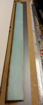
Glassed elevator bottom

I then sanded the TE even.  After sanding I marked a line about 0.32″ forward of the TE for the glass-to-glass continuity between top & bottom elevator skins.
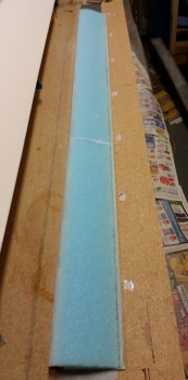
Marked TE for trim

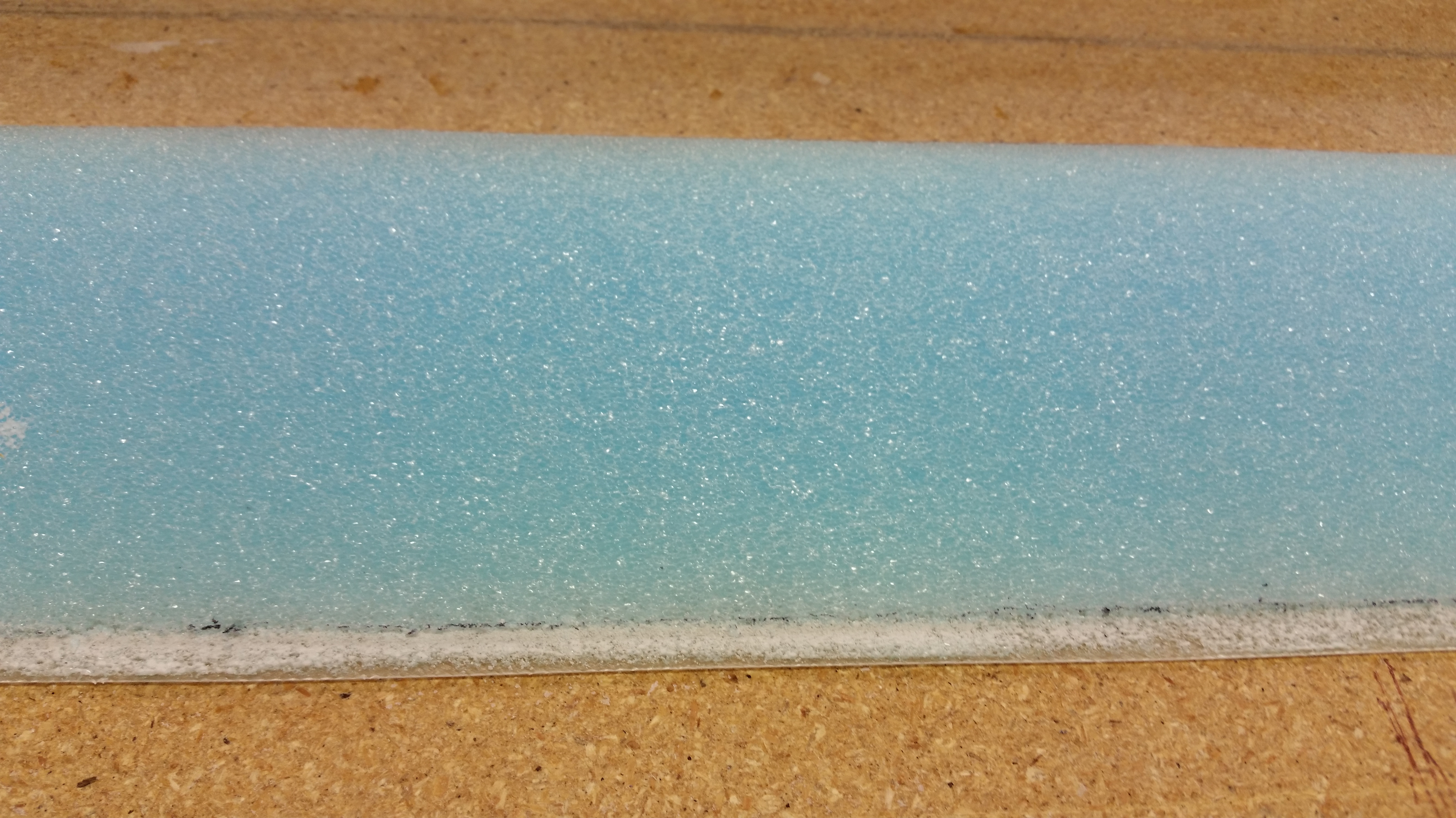
After removing the foam with my razor knife, i sanded down the TE glass with a sanding board.
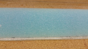
TE initial trim

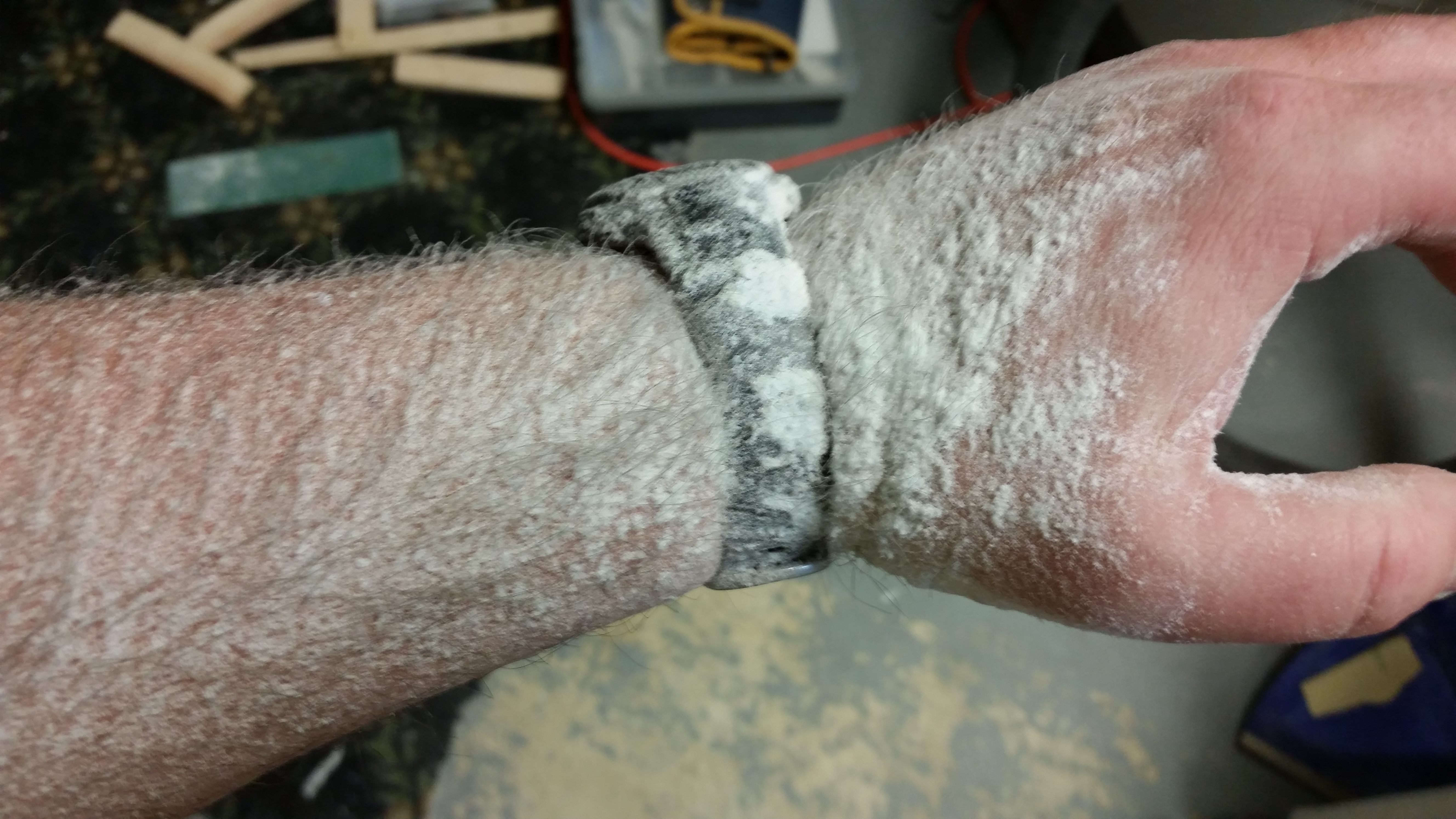
I then Dremeled the remaining crud off the TE to finalize the prep.  And here’s the results: ha!
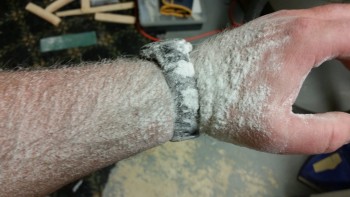
Dremel dust

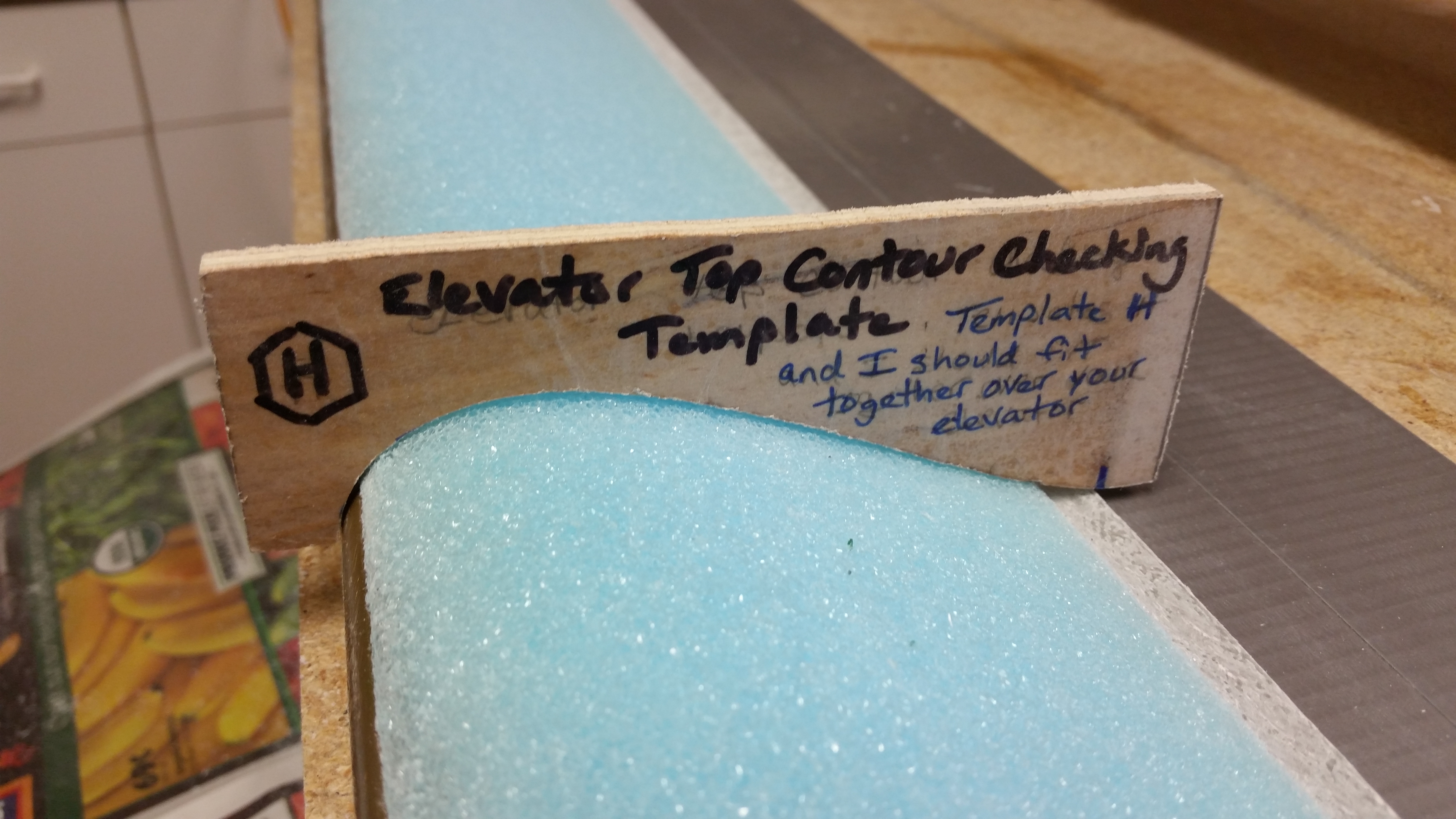
I again did a quick check of the top contour with the “H” template.
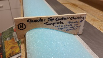
Elevator contour check

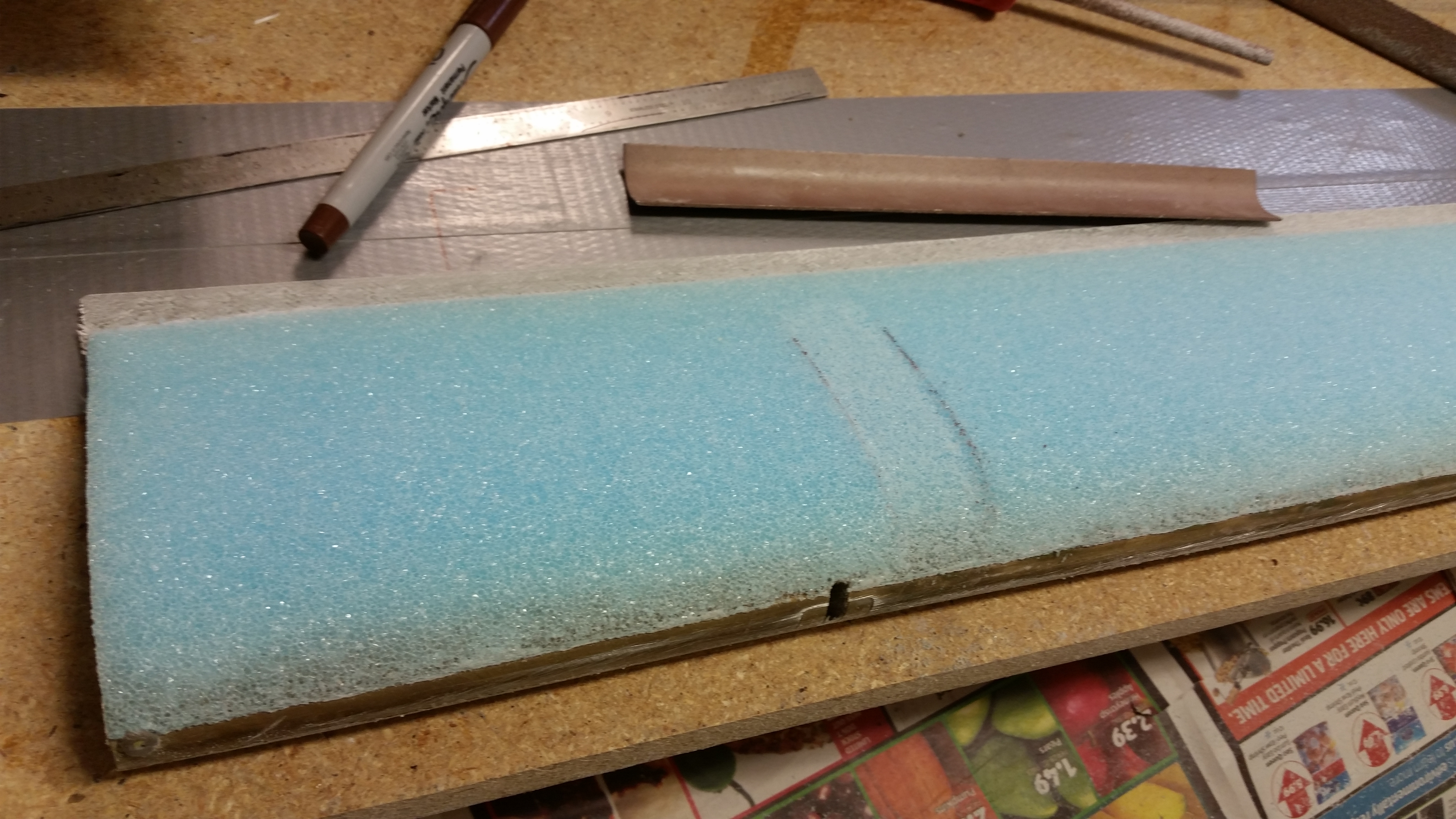
Although I forgot to do this on the bottom (Doh!) I did remember to add the depression in the foam for the UNI plies that attach the outboard elevator weight.
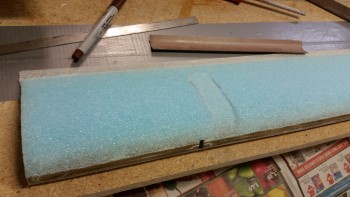
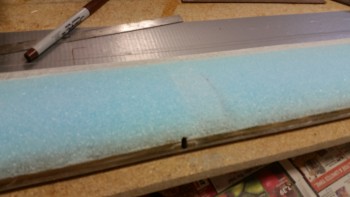
Depression for outboard weight

Depression for outboard weight

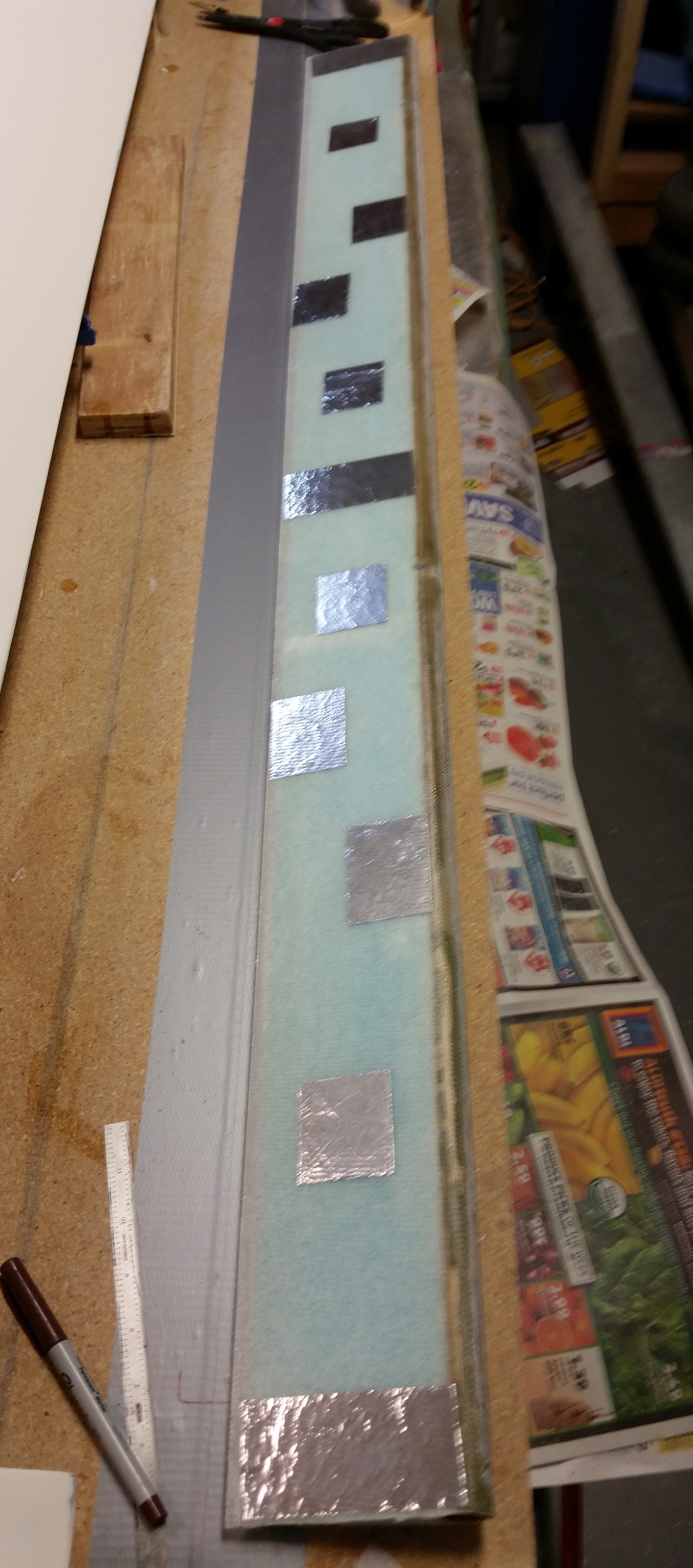
After I finished all the prep actions for the layup, I flipped the elevator over and applied foil tape to the underside of the elevator.  Again, I’m doing this to avoid all the issues I had with the previous elevator, and exactly the reason why I’m rebuilding this elevator!
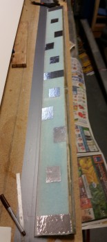
Foil taped elevator bottom

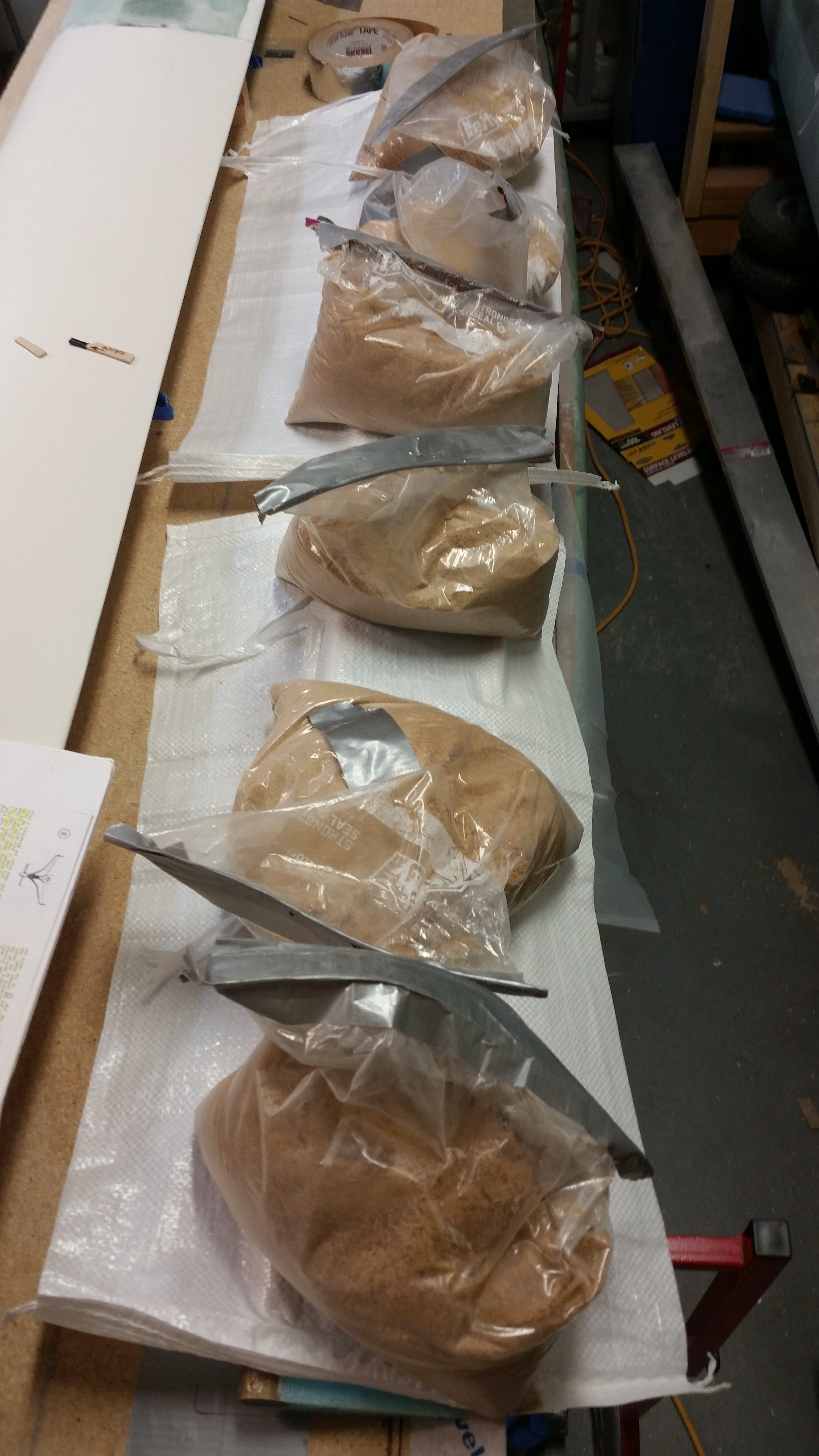
After applying SMALL Bondo blobs to the foil tape pieces I mounted the elevator to the table and then weighed it down with sandbags.
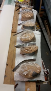
Bondo'd elevator

After affixing the elevator to the workbench with Bondo I had about an hour to go before a work webinar so I started working on the nose gear actuator wiring since I knew I didn’t have enough time to finish the top elevator skin layup.

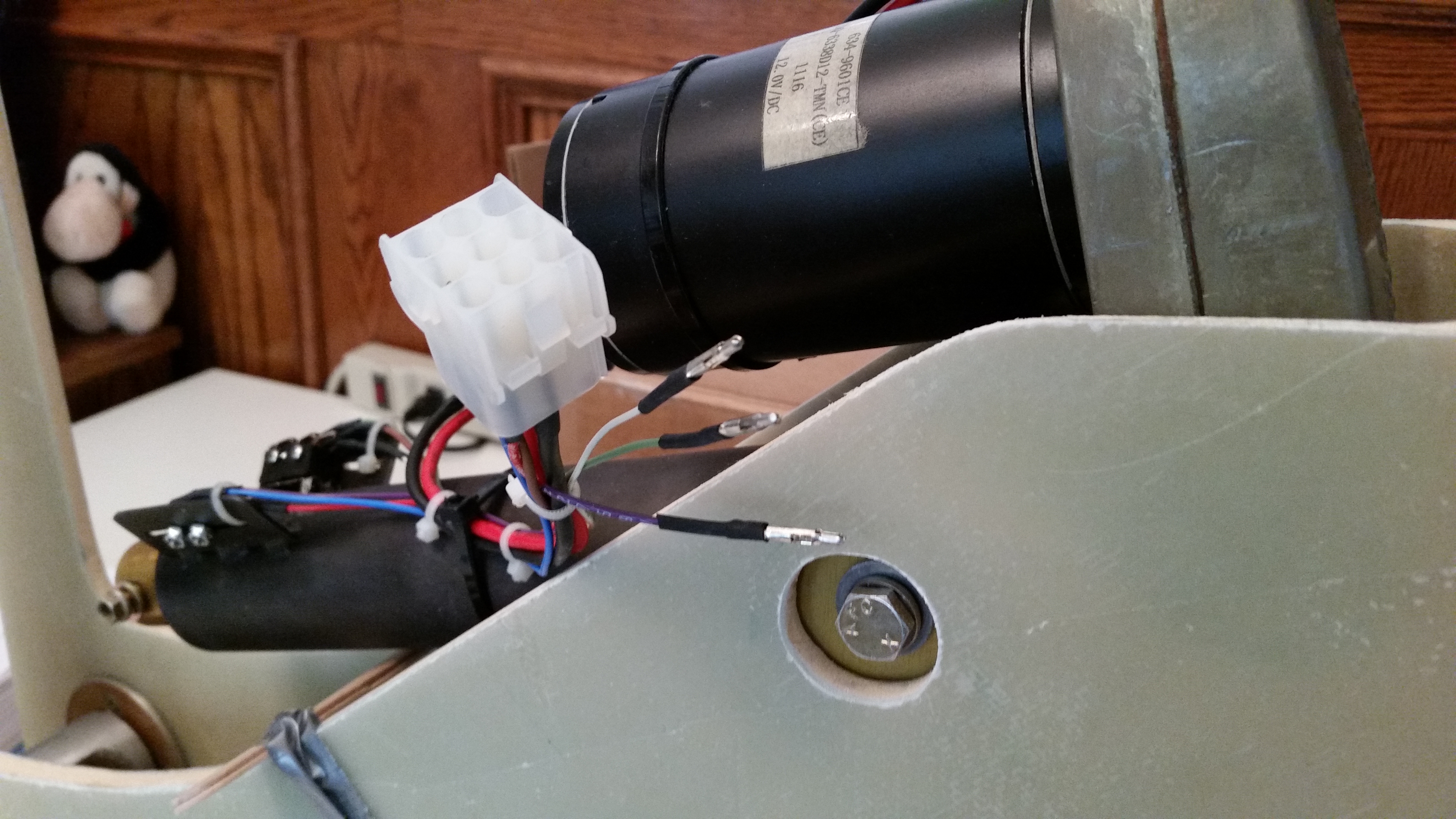
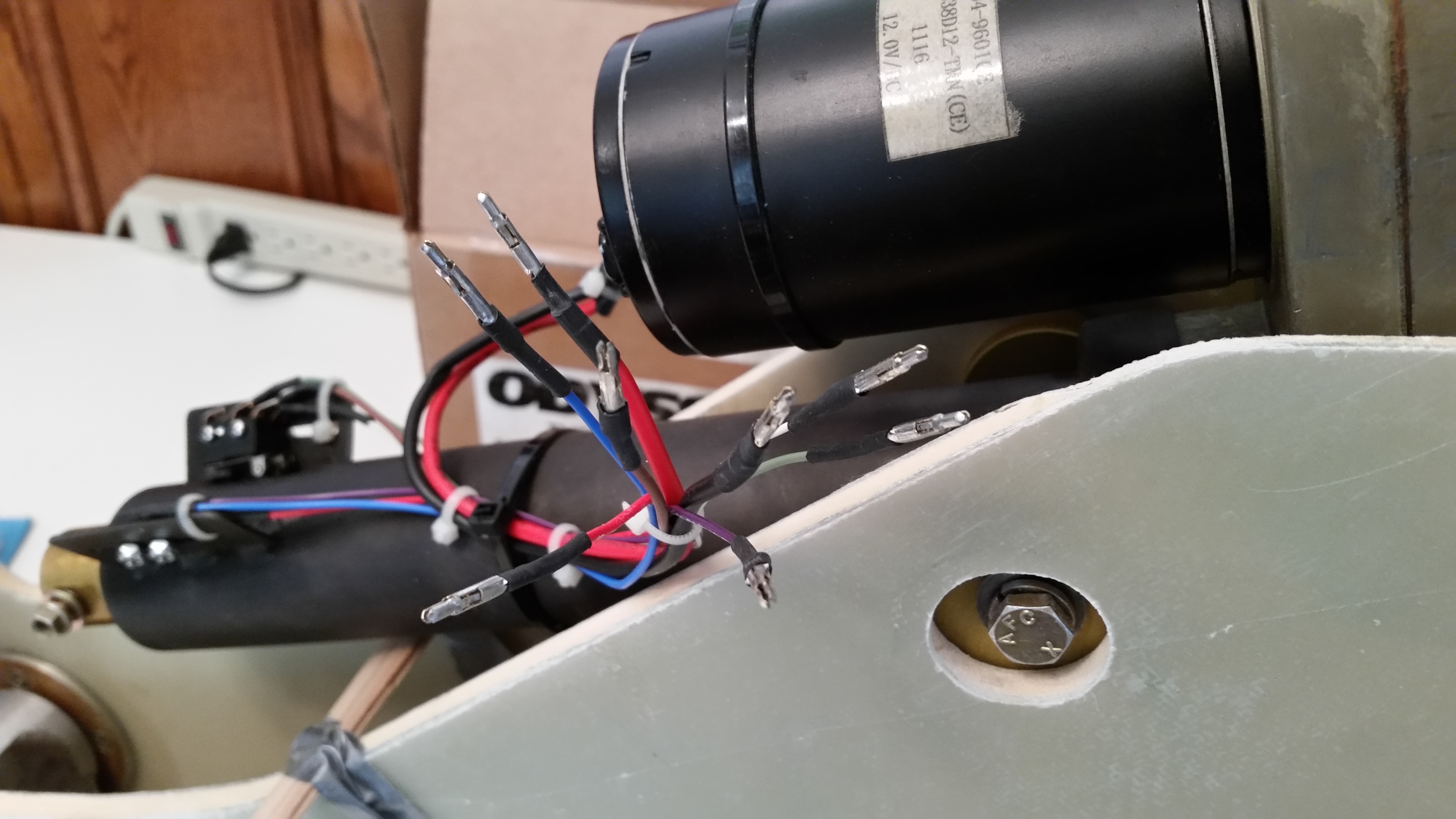
My first task was to pull off the motor side Molex connector, since I’ll be replacing it with an AMP CPC connector.
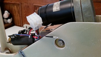
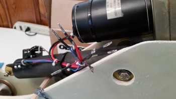
Removing gear actuator Molex connectorGear actuator Molex connector removed

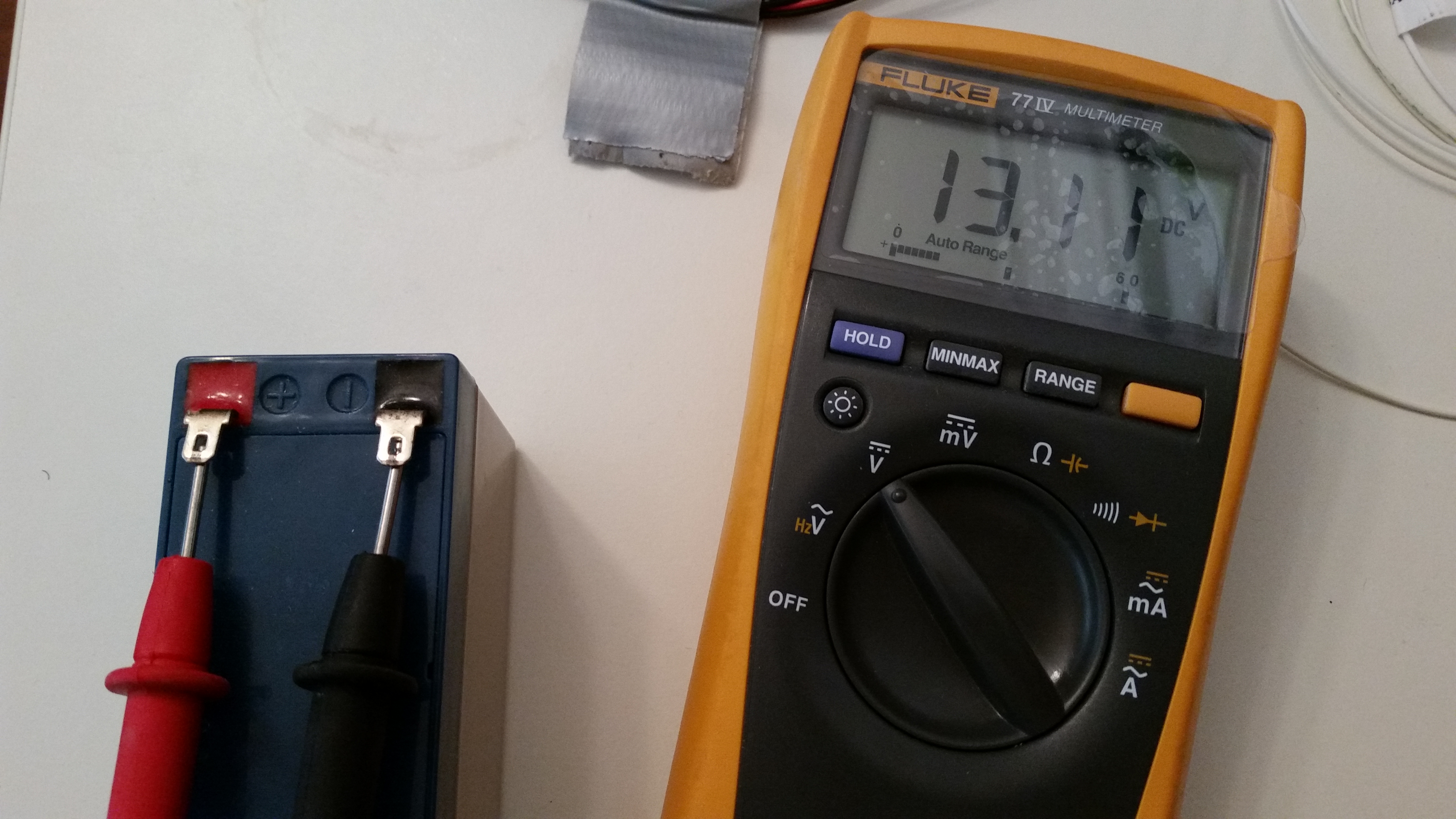
I then double-checked the charge on my nose gear back-up battery.  At 13.11V it looked good and seems to be holding its charge well.
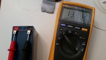
Checking nose gear backup battery

While tracing out & connecting the wires for the nose gear actuator I was able to integrate & plan out the wiring for the gear & canopy warning module.  Basically, I figured out that I can use the up & down limiter “micro-switches” on the nose gear actuator to drive the warning signals to my gear/canopy warning module.  Of course the only issue is that I’ll need to order another AMP CPC connector.  No worries really, since I was going to have to do some finagling with the thick power wires to get them into the 9-pin AMP CPC connector.  A larger connector will be able to accommodate bigger wires.

After my webinar and playing around with the nose gear actuator wiring for a bit, I went back downstairs and vacuumed the foam before starting the layup.
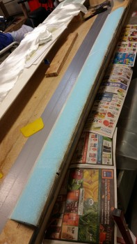
Ready for glass

I then micro’d the top elevator surface.
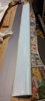
Elevator micro'd

And laid up 2 plies of UNI at 30° in opposite directions.
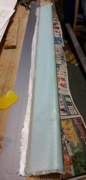
Elevator top glassed

Since I used fast hardener I only had to wait about an hour before the layup was cured to a green stage.  I then razor trimmed the TE.
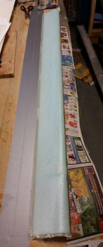
Top elevator TE trimmed

And then applied dry micro on the TE and covered it with peel ply.
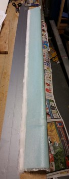
Elevator TE micro'd

I turned on a heat lamp to help get this thing cured as fast as possible.
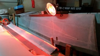
Putting the heat to the elevator

After watching some TV and working on this post for well over an hour, I then went down to the shop to check the elevator top skin layup.  It all looked good and was pretty much cured.  I carefully pulled the elevator away from the table mainly to keep the TE micro from securing the elevator permanently to the workbench and causing real mayhem if I had waited until tomorrow to pull it off the bench.

After pulling the foil tape off the elevator bottom I was ecstatic that the elevator bottom was SO clean & devoid of that Bondo crap that caused all the issues with the previous elevator! I couldn’t help but think how EZ this would have been had I known this trick back when I first built my elevators!
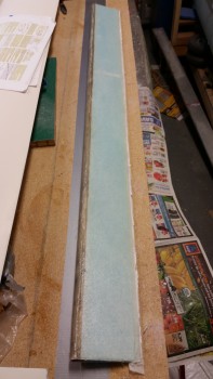
Elevator bottom

My next order of business was to cut away any stray LE glass overlap to keep any of the barbs-from-hell, that may have slipped past the peel ply, at bay.  I also cleaned the blobs of Bondo off the table.  Which thankfully came off fairly easily.
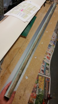
Elevator LE

After cleaning up the LE, I then pulled the peel ply from the outboard weight depression.
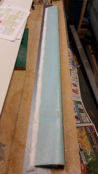
Elevator top skin cured

I then checked the contour again, only this time obviously with the top skin glassed.  Looking good!
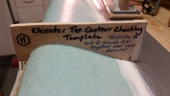
Checking elevator contour

I then focused on the outboard elevator in order to prep that area for the 1-ply BID layup that it will receive.  I sanded the glass edges square and even with NC-6.
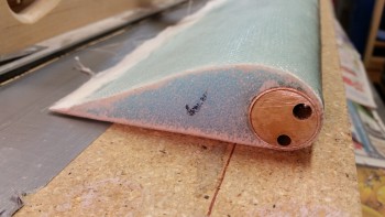
Elevator outboard end & NG6

I stood the elevator up on end & cut the foam to create a wedge shape near the glass for the flox corners.
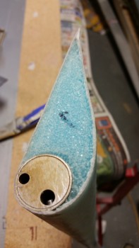
Elevator end foam corners cut

I grabbed a piece of scrap BID and cut it to roughly fit the end of the elevator.
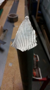
1-ply BID for elevator end

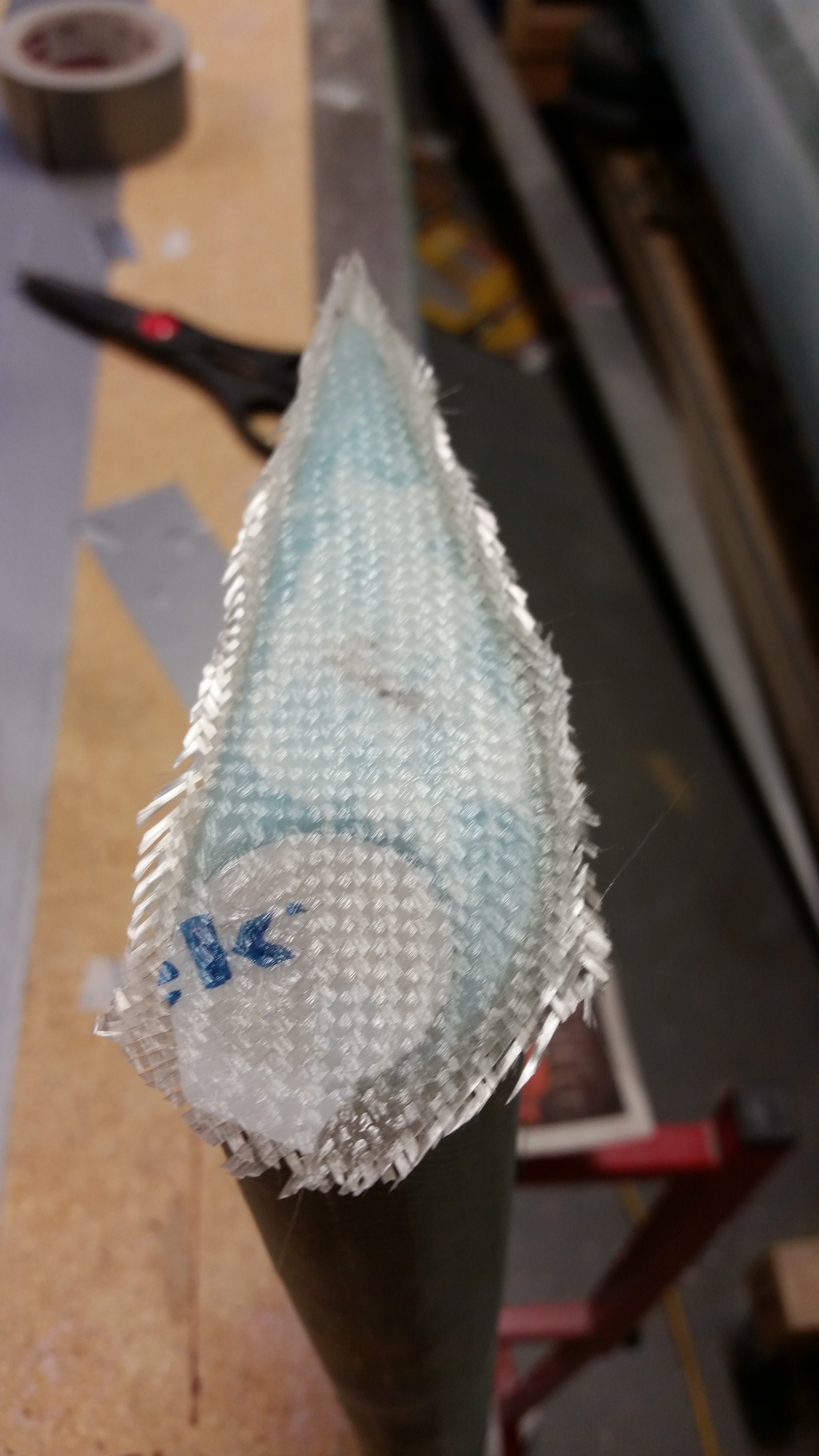
I then mixed up some epoxy with fast hardener, made some flox for the corners & some micro for the foam.  I then laid up the 1 ply of BID, trimmed the glass a little and let it cure.
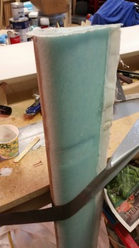
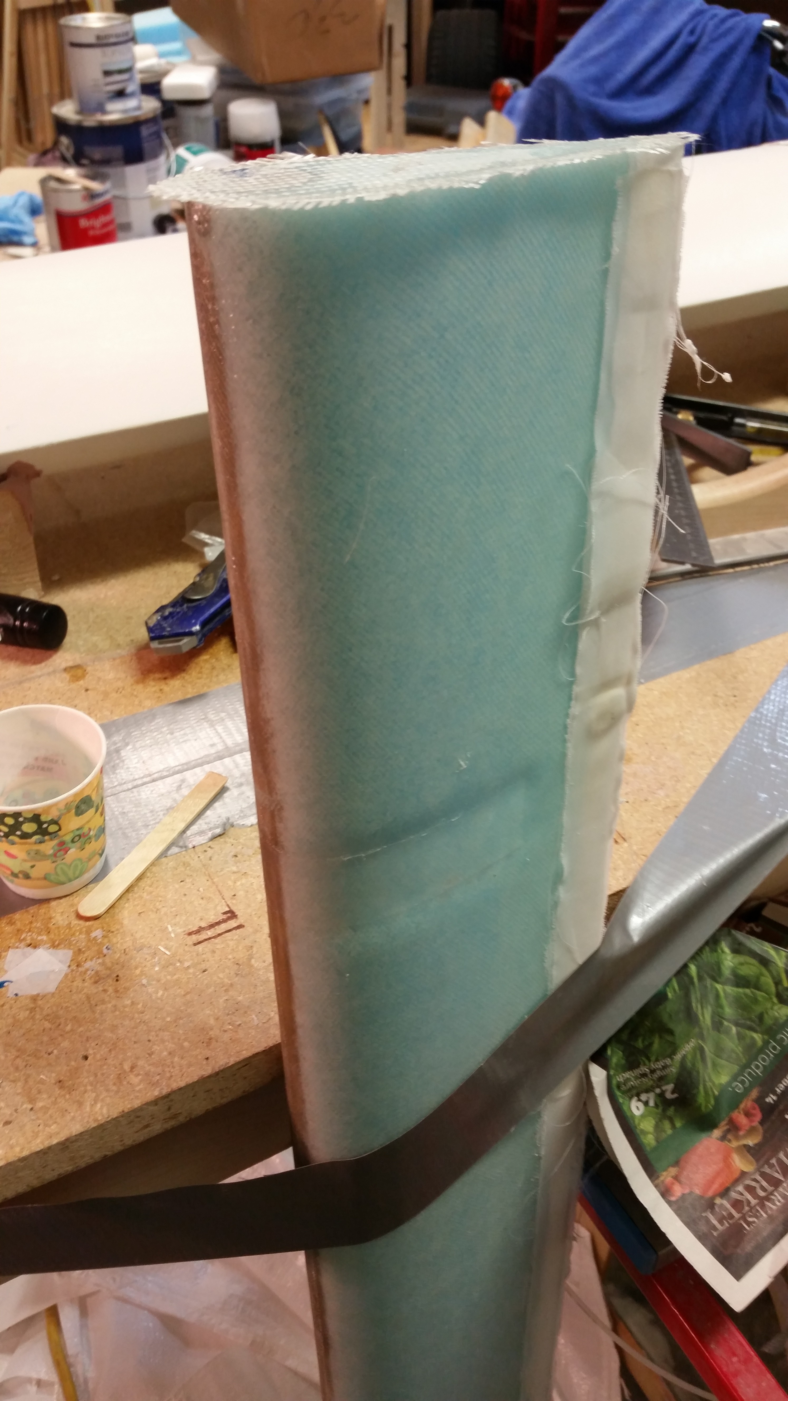
Elevator end BID layup

Elevator end 1-ply BID layup

In a couple of hours I’ll check the layup and razor cut the edges.

Tomorrow I plan to finish the elevator rebuild by sanding the TE to its final shape and also attaching the outboard elevator weight.  Then it will just be a matter of cutting, drilling & cleaning up the hinge slots & bolt holes and the elevator rebuild will be complete!


Chapter 11 – Elevator Redo

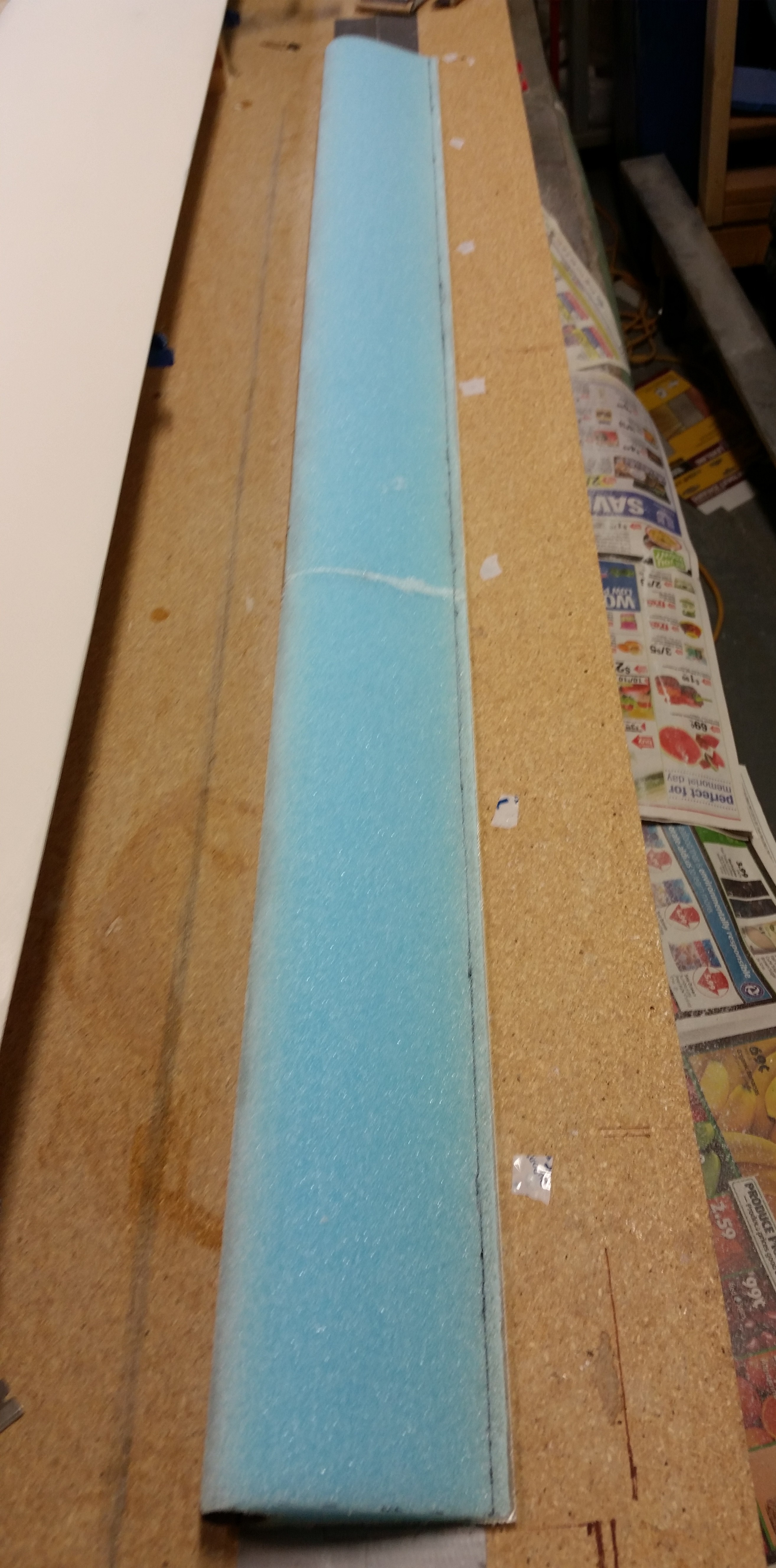
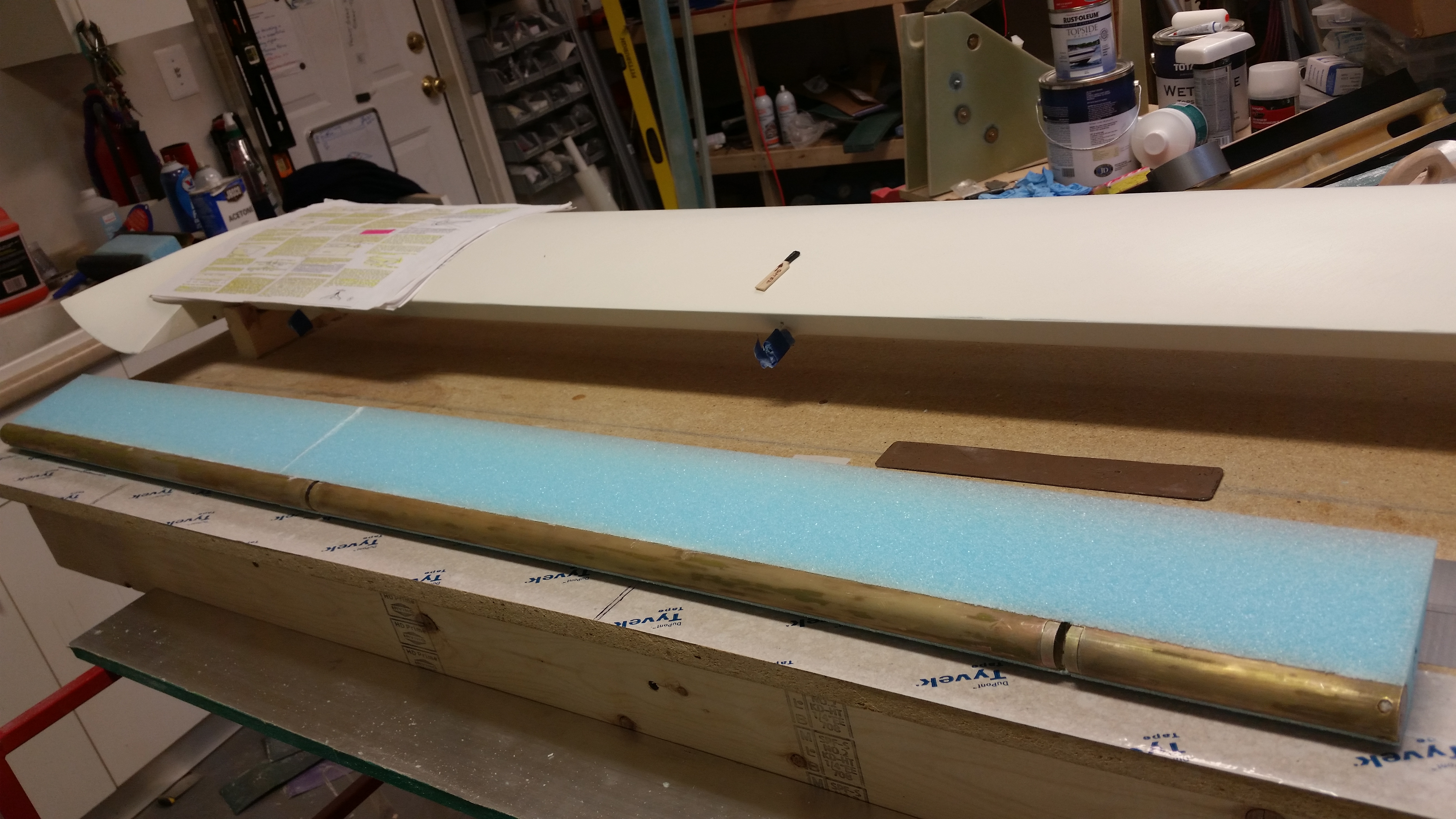
Today I focused entirely on the elevator.  Below is the elevator core micro’d to elevator tube.

Foam attached to tube

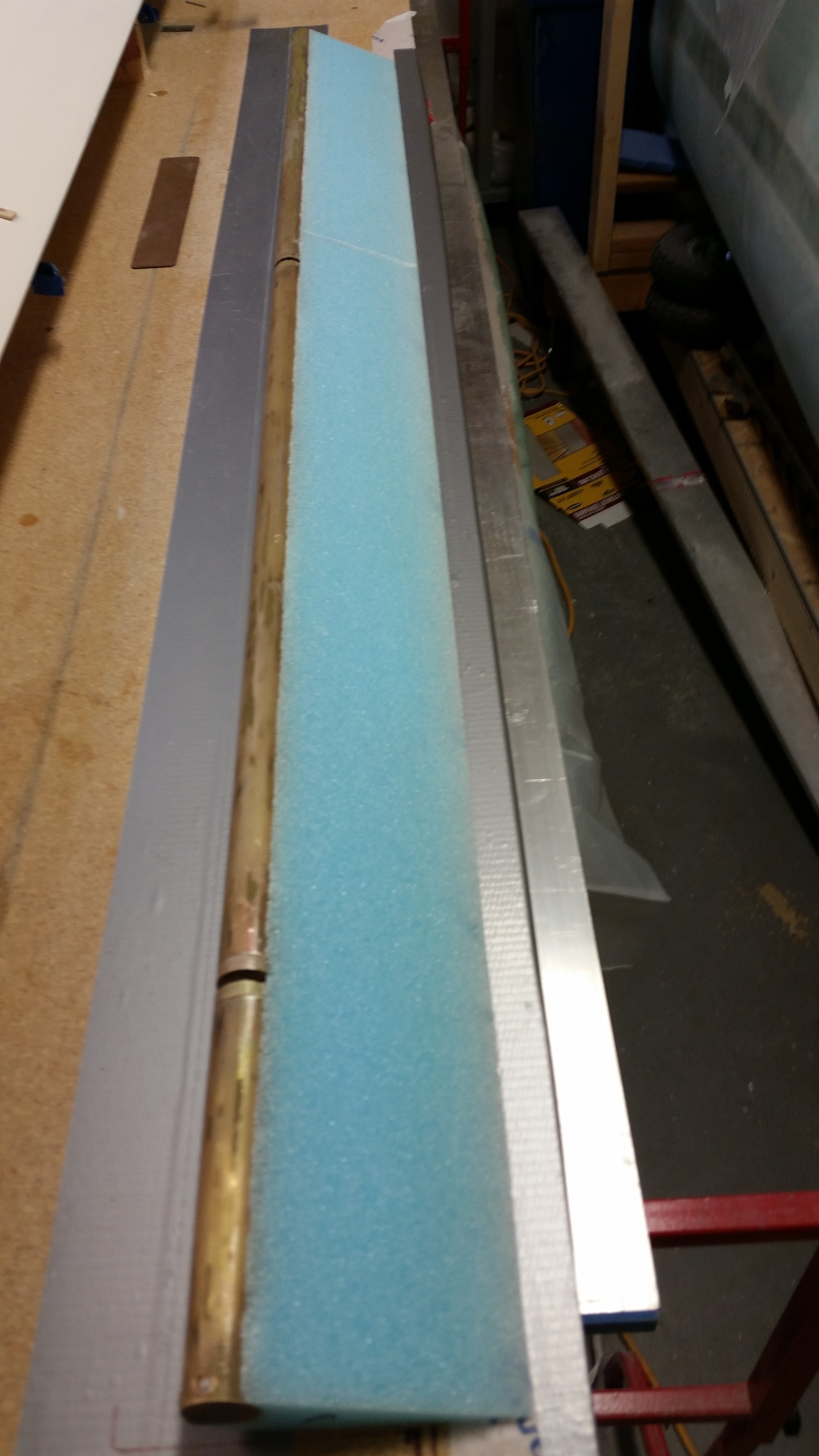
I prepped the tube by taping up the holes in the hinge pin hard points (NC2s) and the elevator tube end insert (NC6).

Prepping tube for glass

Before glassing the bottom skin I lightly sanded the bottom front edge of the foam core where it intersects with the elevator tube.  I also cleaned up the micro at the seam between the two elevator foam core pieces.

Elevator tube with new foam core

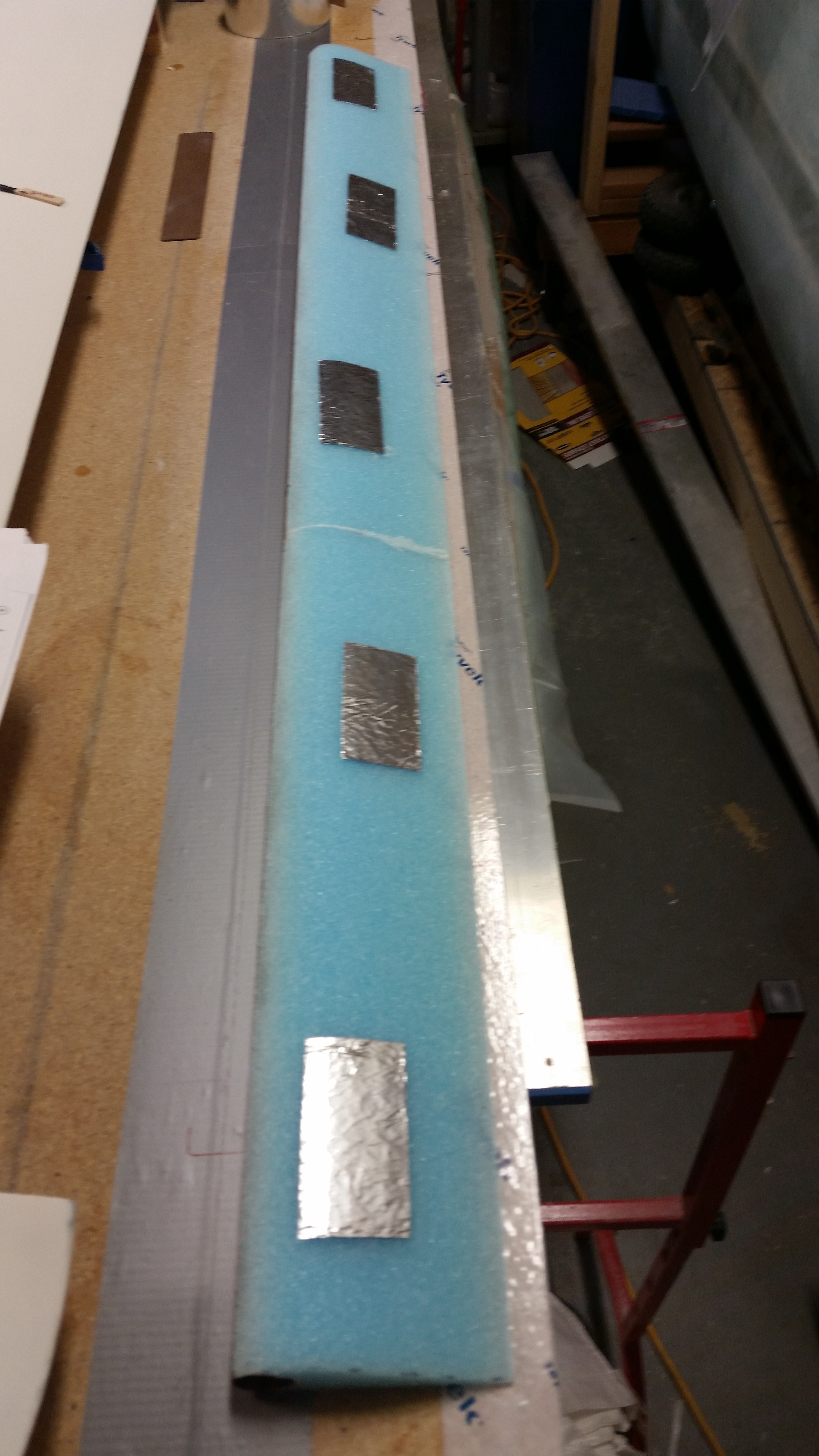
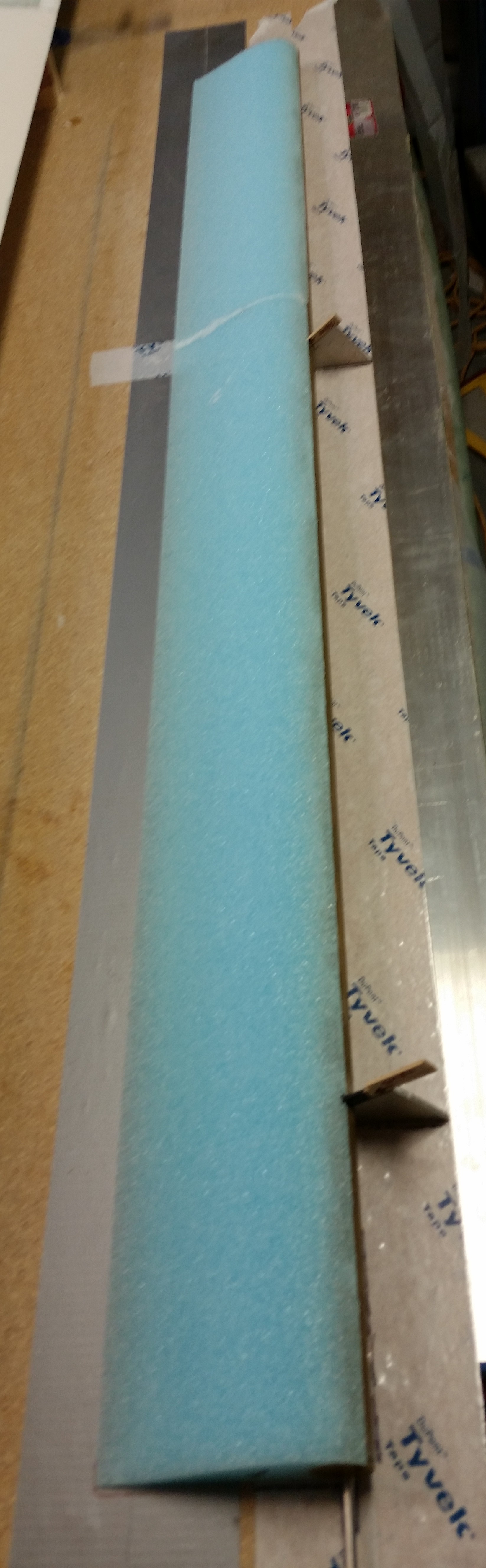
To minimize any damage to the foam surface, and thus minimize backfills to the foam, delams and in turn weight, I applied foil tape to the surface of the elevator top.  I figured I would try this method instead of applying 5 minute glue directly to the foam.

Foam preservation attempt!
I then quickly checked the bottom contour of the elevator.

Double checking bottom profile

And then mixed up some 5 minute glue, applied a good sized drop to each piece of foil tape, and attached the inverted elevator core to the work bench.  I weighed down the TE with sandbags.

Weight on elevator during 5 min cure

After the 5-minute glue cured, I did a final check on the foam before I glassed it.

Elevator bottom ready for glass

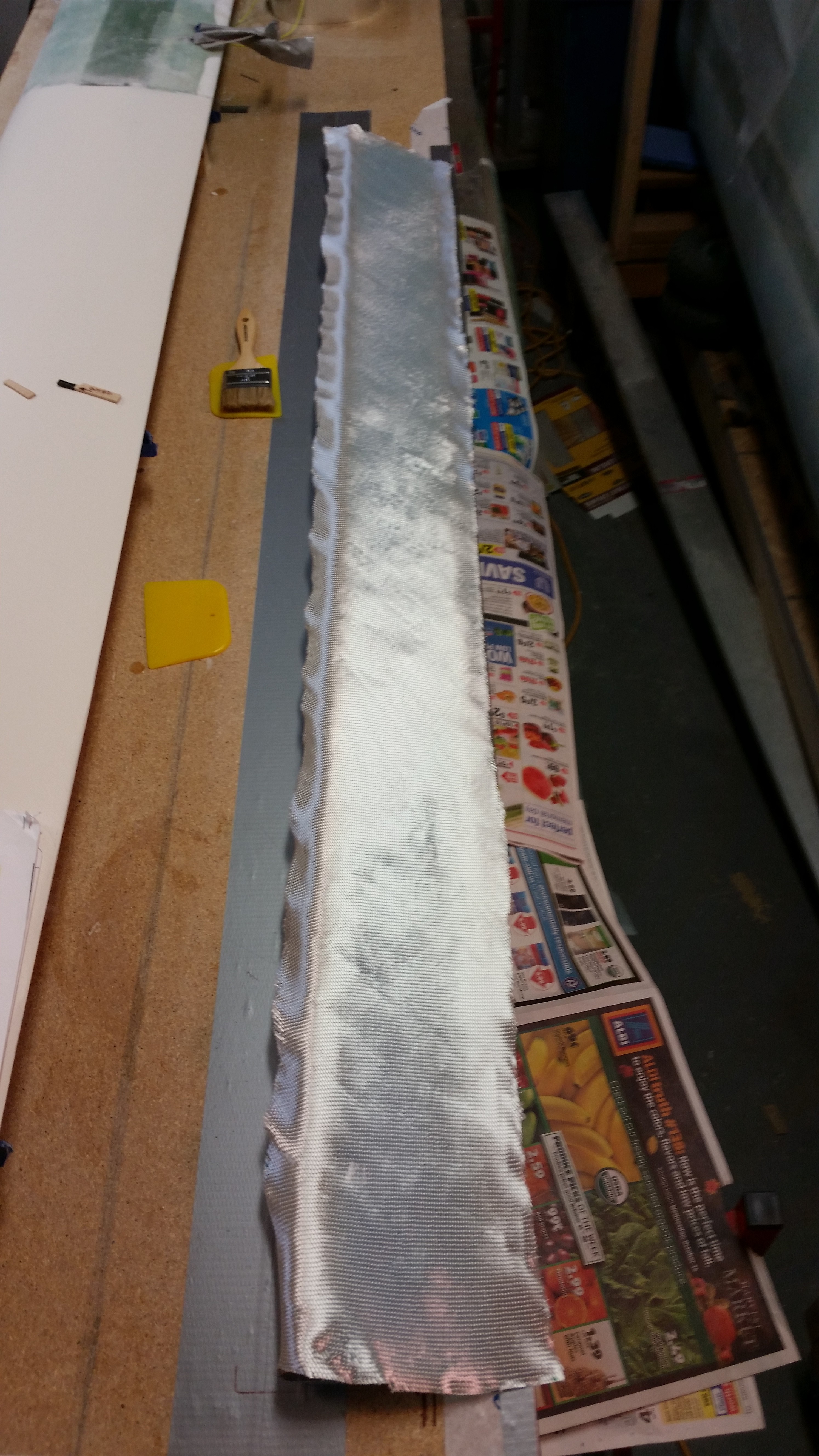
I also checked the UNI glass to ensure it fit.  I then glassed the lower elevator skin 2-ply UNI layup using fast hardener.

Checking glass fit

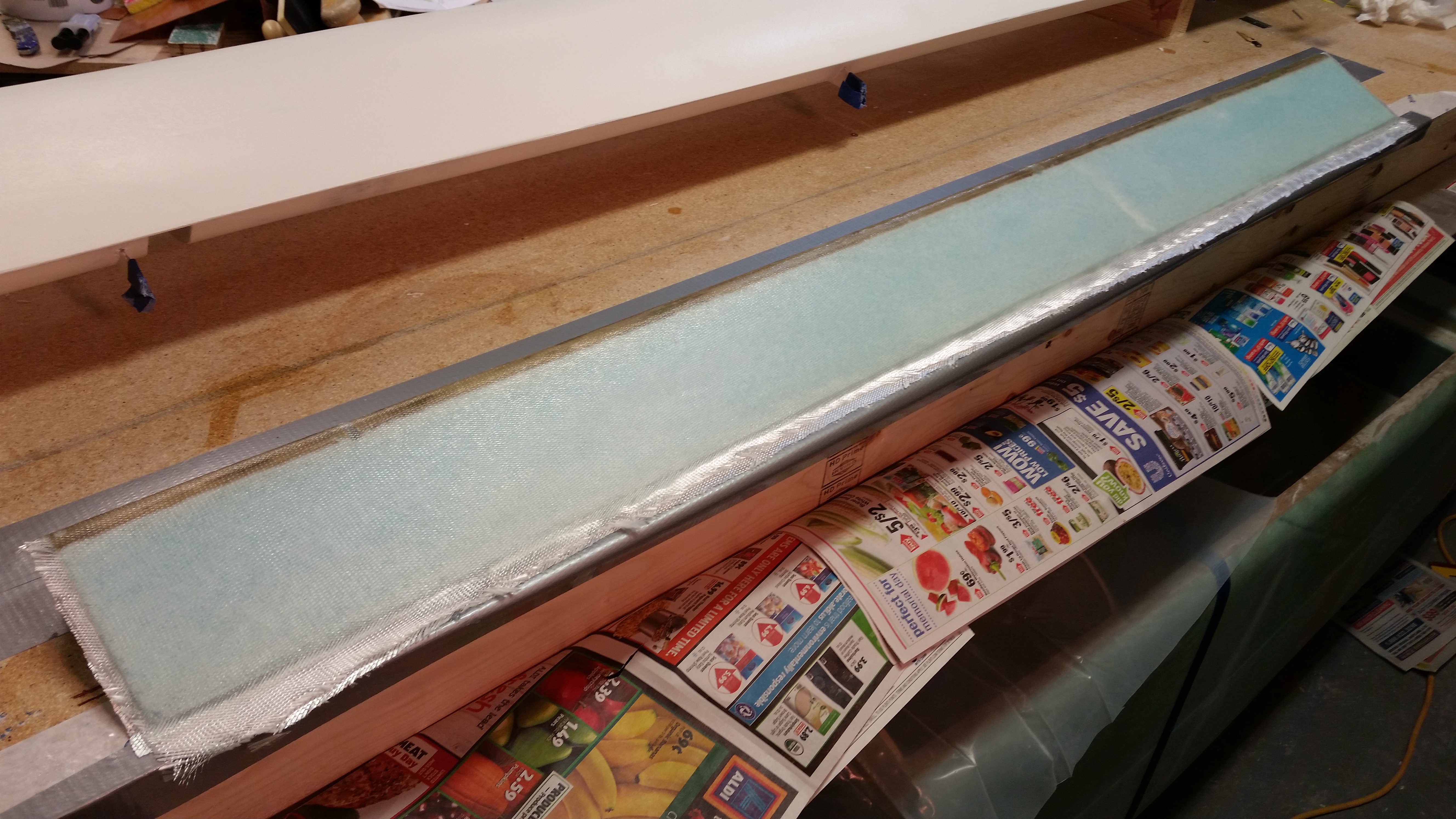
Here’s the (new) glassed bottom of the elevator.

Cured bottom elevator skin

Here are some shots of the finished elevator bottom, in various stages of razor trimmed glass.

Cured bottom elevator skinCured bottom elevator skin

Cured & trimmed bottom elevator skin

I was going to glass the top skin of the elevator as well, but I went out to dinner tonight and it took forever to get our food, so I just didn’t make it back in time to fire up the Dremel tool to trim the TE in order to get good glass-to-glass contact between top & bottom skins.

Tomorrow I’ll prep the elevator & glass the top first thing, and if all works out I’ll actually get the outboard elevator end glassed as well.


Chapter 11, 13 & 22 – Tubing it…in a good way!

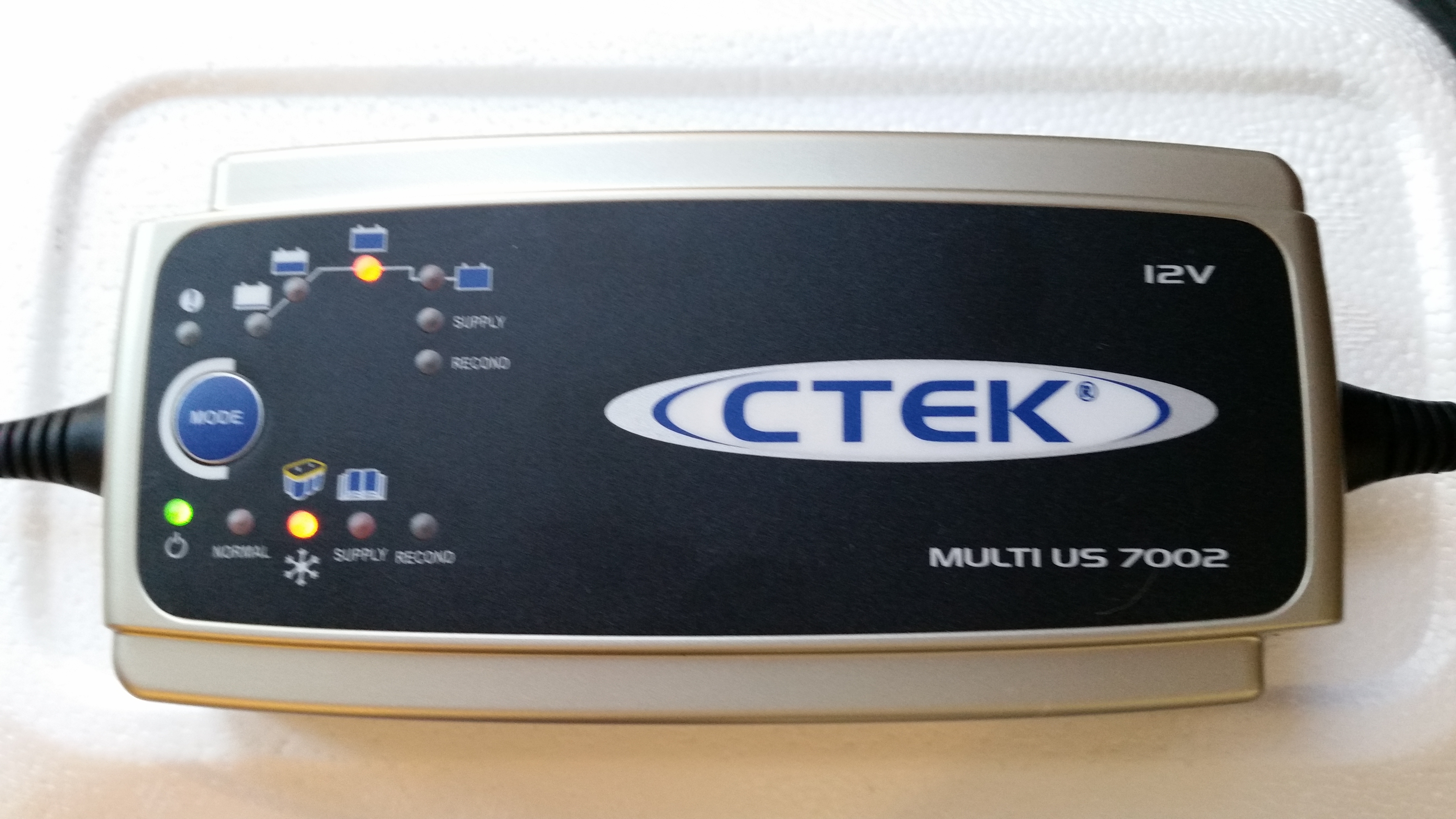
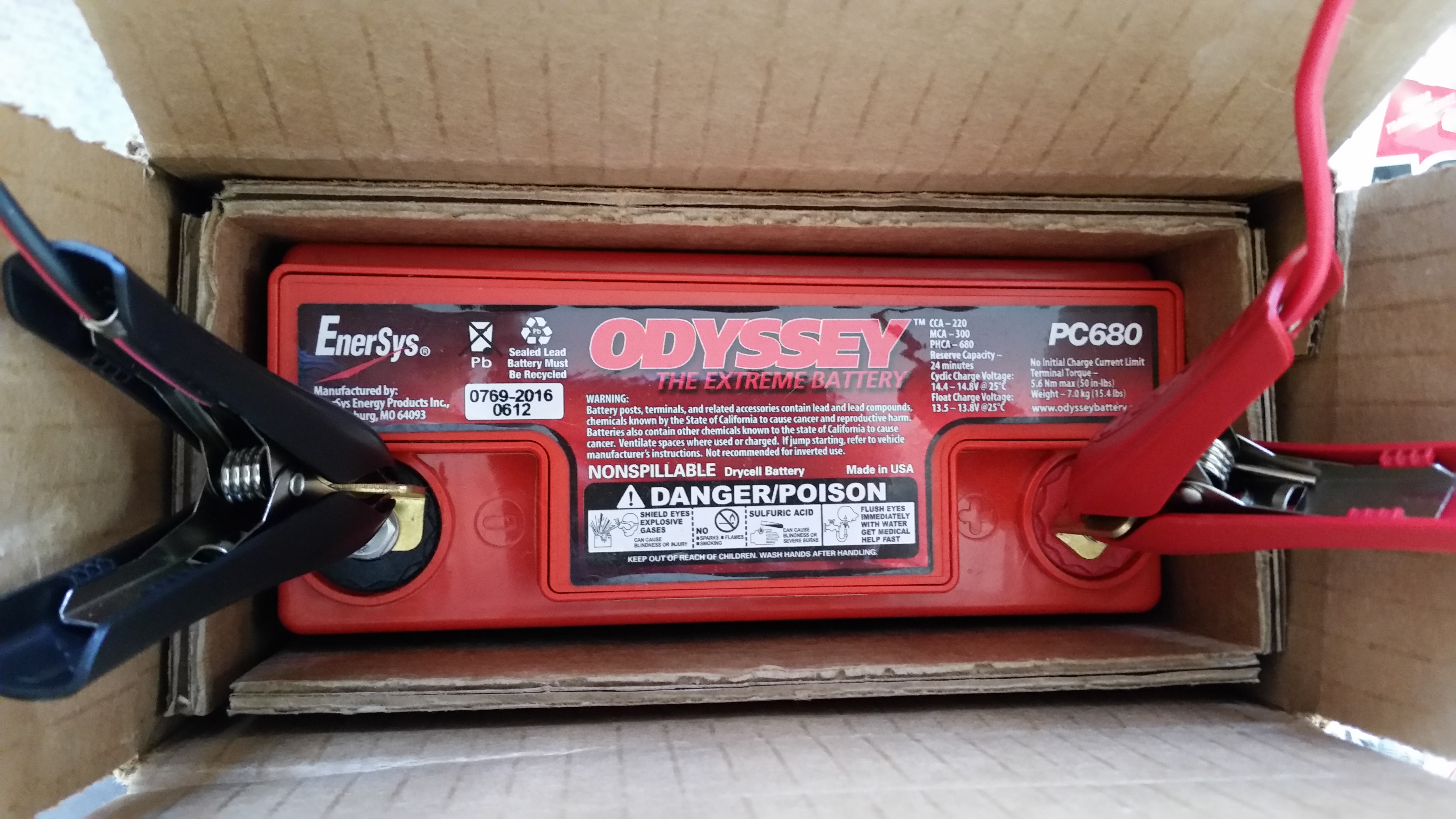
Today the UPS guy showed up with the battery charger I ordered from Amazon last week. I ordered this battery charger because in reading the manual for the Odyssey PC680 battery it stated that if the battery charge fell below 12.65 volts, than it needed to be charged before using it.  When I checked the battery the multimeter showed 12.57 volts, clearly below the threshold required to be able to use the battery as per the instructions.

Of course I knew I would need a battery charger eventually since the Odyssey PC680 is an Absorbed Glass Mat (AGM) type that is immune from acid spills and gas venting, and thus has some unique charging requirements to ensure the battery is maintained in an optimized state before it’s actual use in the Long-EZ.  An interesting side note to this battery is that it can be mounted in any position.

Currently, the main reason I want to use the battery is to test the nose gear actuator.  So when the battery voltage tested low I checked the Odyssey website for approved battery chargers.  After assessing a few battery chargers online, I decided on this one and ordered it.

Odyssey PC680 Battery Charger

I hooked up the battery to the new charger before heading out to a meeting I had at the office. Before I left for my meeting I went upstairs and changed clothes –about 5 minutes– and when I did a final check before walking out the door the charger had already completed its first 2 phases and was in the basic charging phase.  This was a good sign since the initial phases are conditioning cycles that bring a battery back to the point where it can simply be charged in phase 3, where again, my battery was before I even left the house.  By the time I returned about 2 hours later, the battery was fully charged and was at 13.87 volts.  Not bad!

I’m discussing the battery at this point since the short term use of the battery is to test the nose gear actuator (Chapter 13) while of course the long term use will simply be as the aircraft’s primary power source (Chapter 22).

Odyssey PC680 Battery

I then focused on the new elevator build.  I pulled the elevator tube out of the vinegar-filled PVC pipe and did a final clean on the tube.  I then washed down the elevator tube with Simple Green before taking it outside to Alodine it.

Final Cleaning Elevator TubeFinal Cleaning Elevator Tube

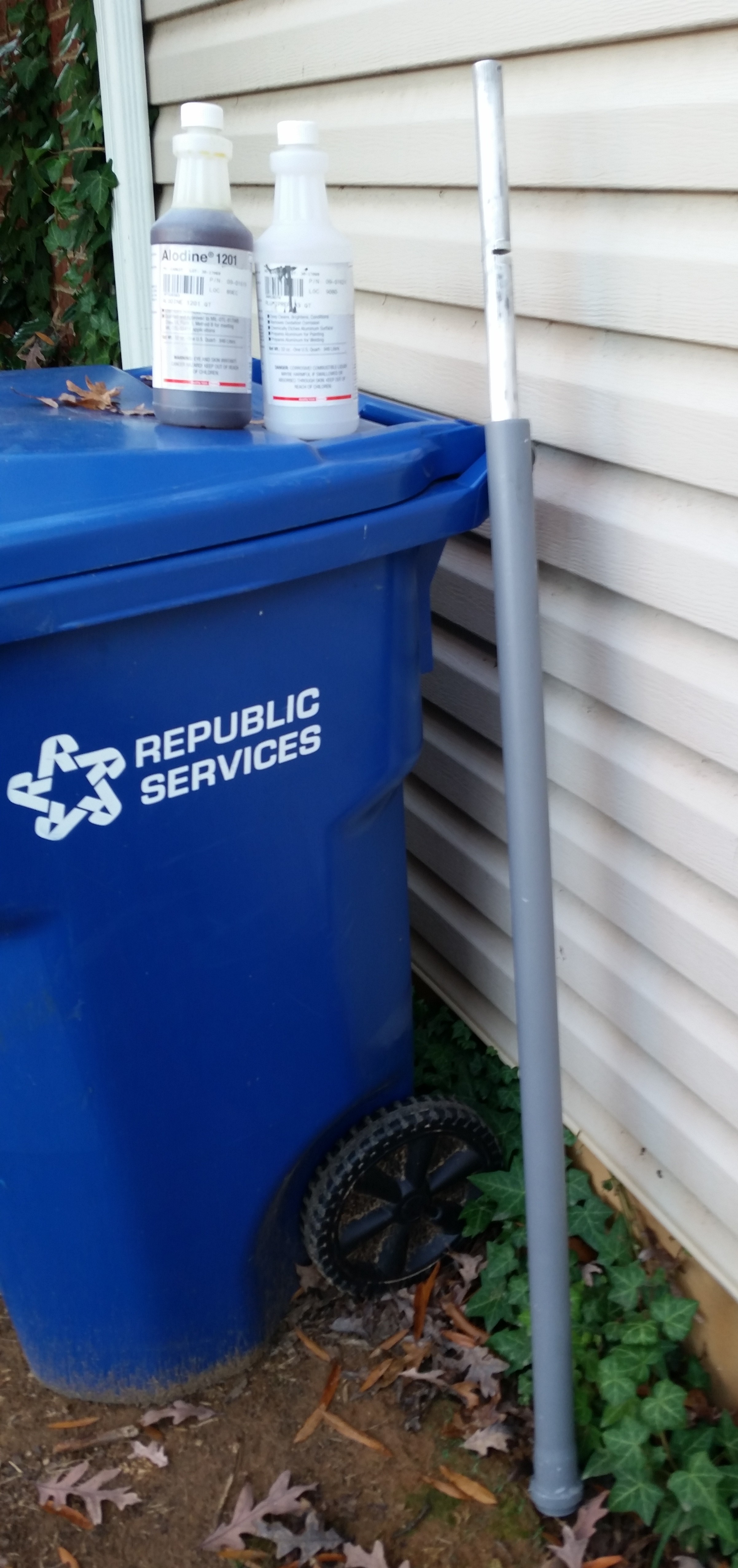
I washed out the PVC pipe, filled it full of Alumaprep, and then submerged all but about 18″ of the elevator tube into the Alumaprep.  Since my Alodine chemicals are weak, I left the tube in the Alumaprep for about 8 minutes before taking it out, rinsing it with water and giving it a good scrub.  I then put it back into the Alumaprep with the other end in first.

After the Alumaprep wash, I rinsed down the tube and did the same process in PVC pipe #2 filled with Alodine.  Again, I left it in there way longer than normal, about 8 minutes per side since the Alodine was weak.  After the time had passed, I again gave the whole tube a good rinse with clean water.

I hung the freshly Alodined elevator tube up to dry and then began to prep for micro’ing the elevator foam core to the tube.

Now, I was seconds away from taking a picture of the Alodined elevator tube when my long lost buddy Greg showed up.  Unfortunately when I loaded up all my pics at the end of the evening I realized I hadn’t taken the picture, which is unfortunate because I thought the Alodined tube turned out rather well.

Alodining Tube

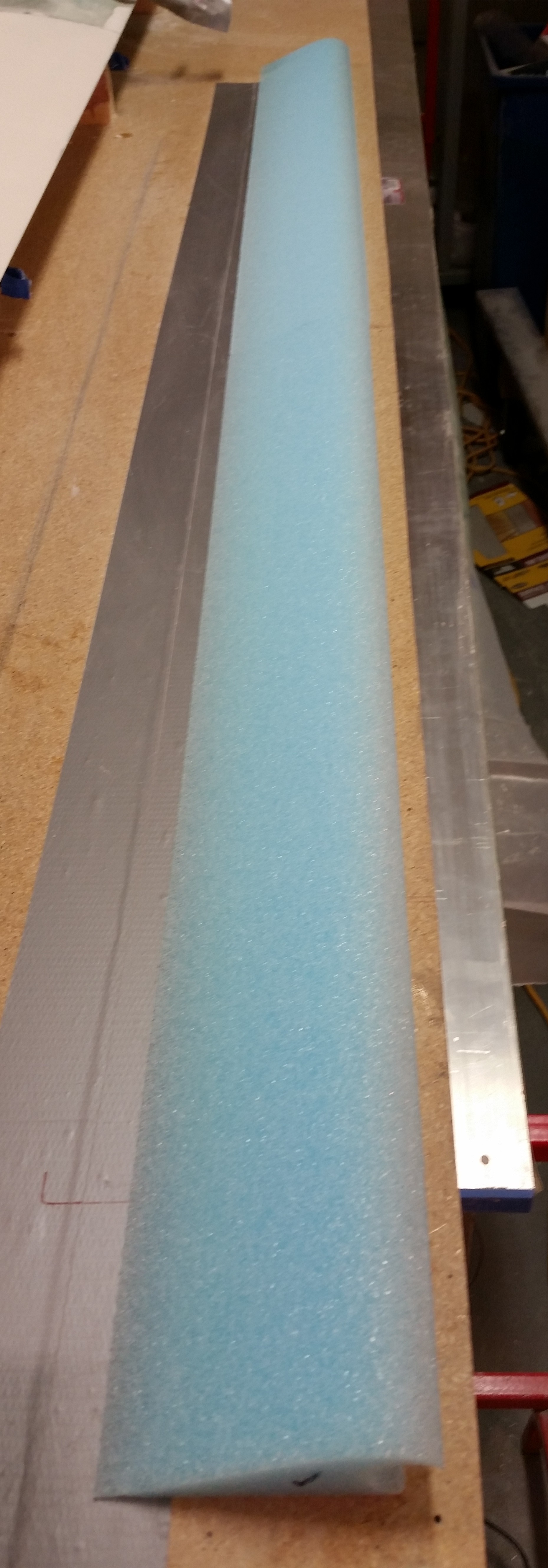
As for the foam cores, since I ordered only the elevator cores from Steve at Eureka CNC, he could only send me the cores cut in half for shipping purposes.  The pics below are shots of one elevator core cut in half.

Elevator cores

Elevator core halves

Here are the two halves end to end.

Elevator core

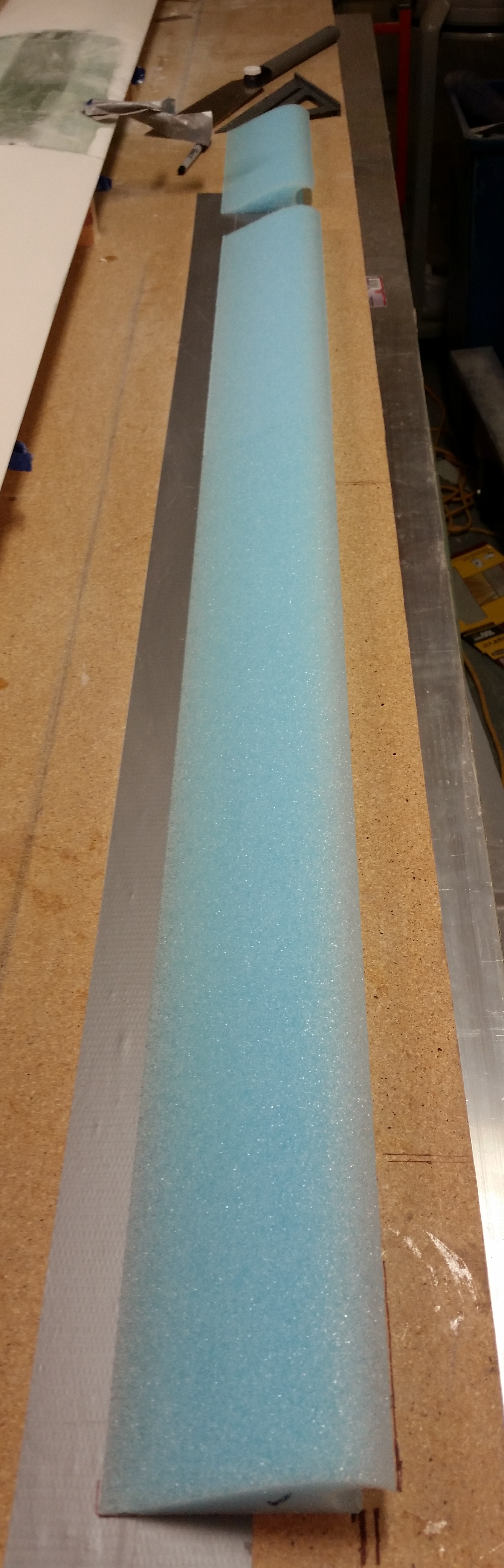
I marked the second elevator foam core piece to cut to length, making the total combined length of these elevator foam core pieces 53″ to match the length of the elevator tube.

Cutting elevator core to length

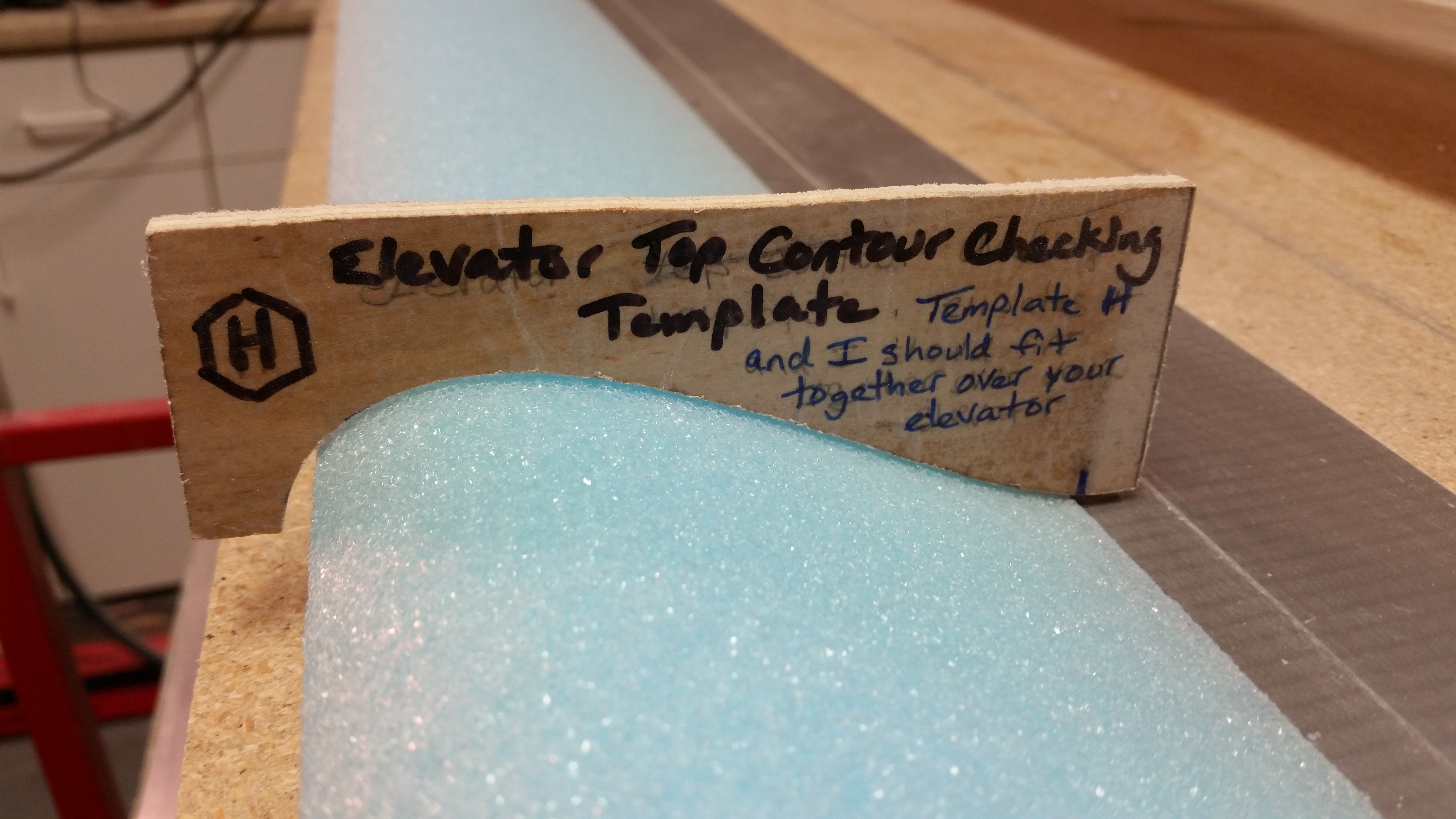
I then did a quick check of the top elevator contour with template “H” and it looked good.

Quick check of contour

Here’s a pic with the elevator core pieces cut to the proper 53″ length. [Note: these are the correct length of MY elevator cores for this airplane, since I widened the fuselage at all the bulkheads, my F22 & F28 are just a hair wider than the stock plans dimensions.  This widened fuselage resulted in slightly shorter elevators.]

Elevator core cut to length

And here’s the two elevator core pieces micro’d to the elevator tube.  Yes, the elevator reconstruction is under way!

Elevator foam micro'd to tube

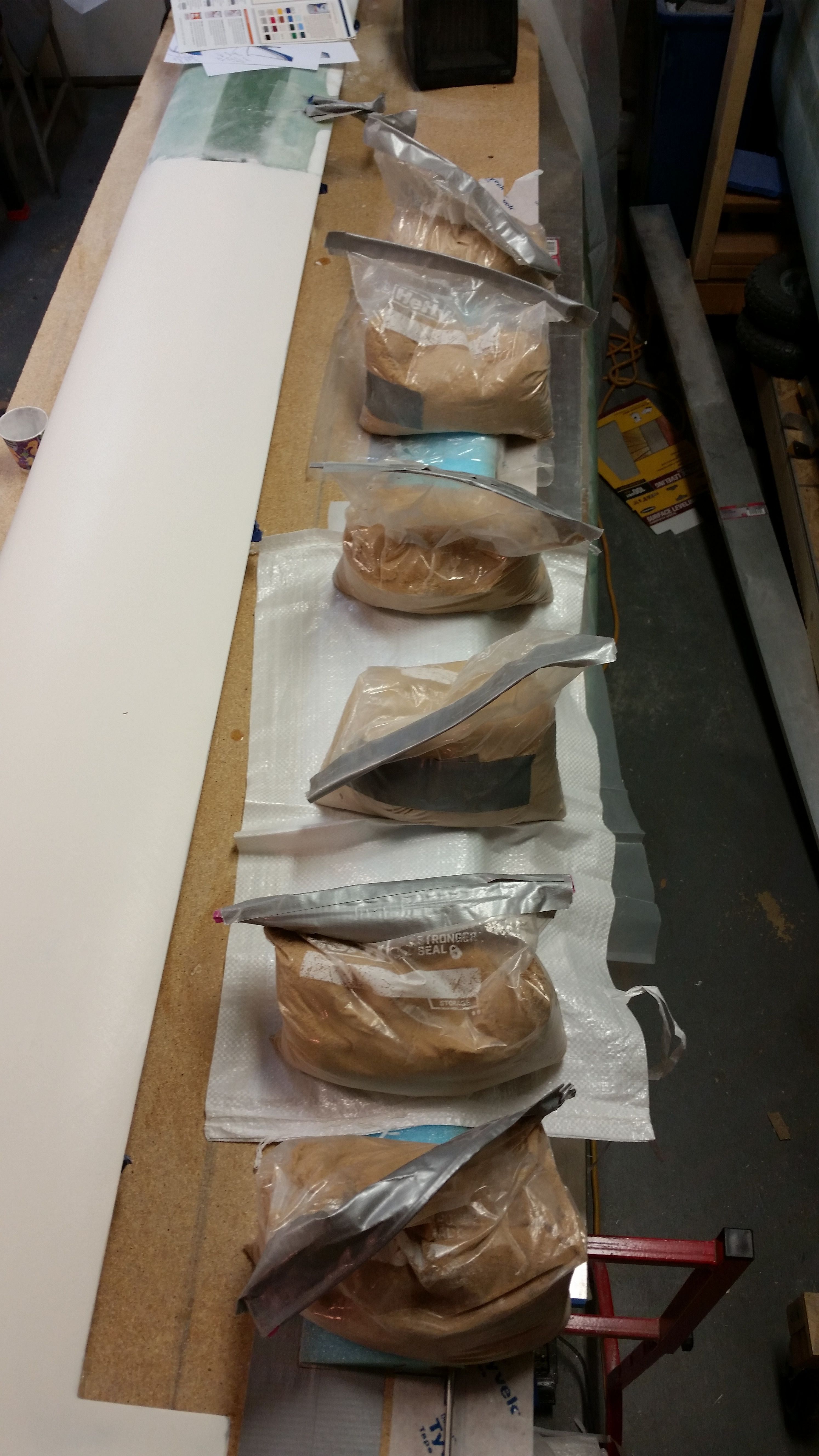
As per plans I weighed down the elevator core & tube with sandbags to keep them firmly in place.

Sandbags on micro'd elevator foam

Tomorrow I plan to glass the bottom skin, and possibly the top skin, of the elevator.


Chapter 11 & 25 – Cleaning the Tube

After a meeting I had in the office earlier today I ran over to Maryland to pick up a different brand of boat paint.  I’m going to do some tests and will report back on the entire plan later on.

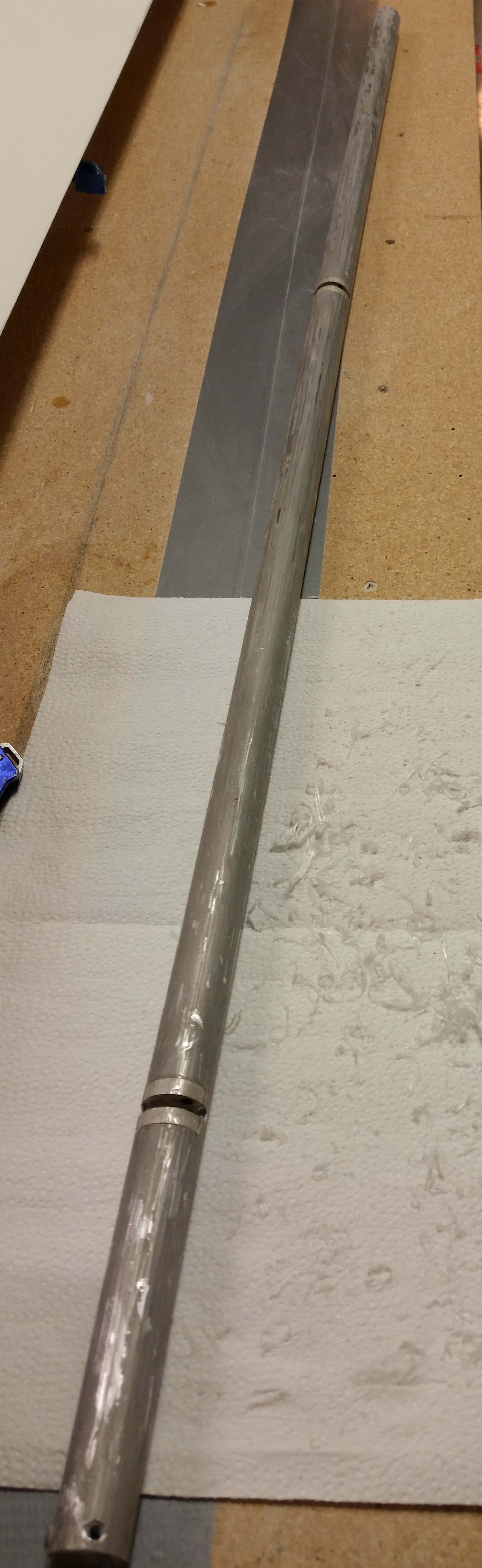
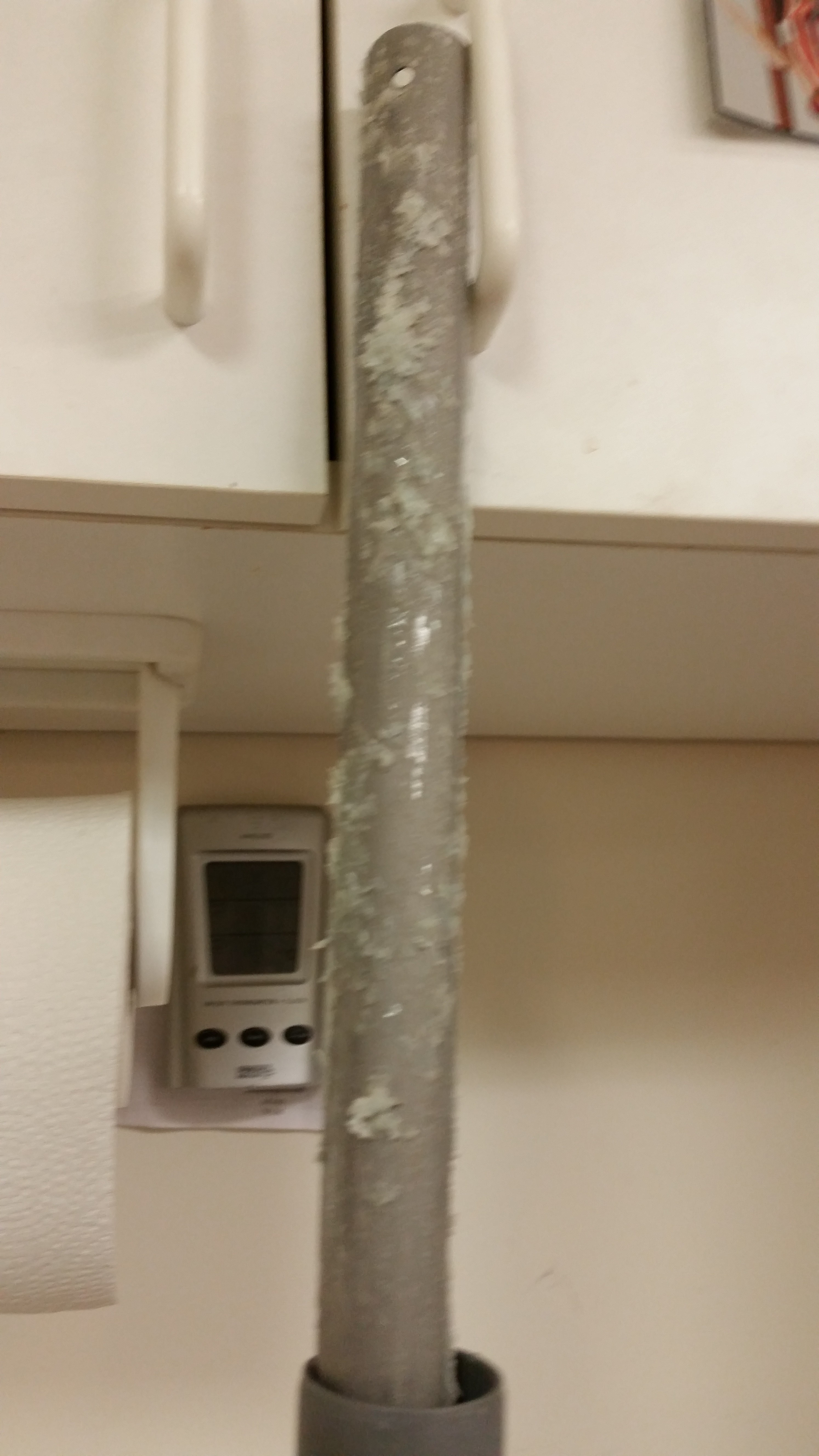
Upon returning home I took the elevator tube out of the PVC tube filled with white vinegar and flipped it over to get the untouched 25% into the vinegar.  I cleaned off the majority of gunk with paper towels, then grabbed my razor knife and started cleaning off the dead glass.  I got as far down as the second hinge hardpoint (NC2).

Elevator tube - foam gubersElevator tube - dead glassElevator tube - Initial clean

After getting as much of the soaked dead glass off the tube as possible, I set the elevator tube back into the PVC tube filled with vinegar to soak.

Elevator tube soaking

After I put the elevator tube back in the vinegar cleaning solution, I then sanded the canard surface starting with 80 grit on the long board, and then switched to 120 grit on the long board as well.  I then switched to 150 grit paper and hand sanded each swoosh tip.

I was still getting a fair amount of residue on the sandpaper and had to clean it off the paper at regular intervals.  After going through another few sheets of very expensive long board sandpaper (although tonight was much better than last night as far as residue buildup), I decided to wait until tomorrow to finish sanding the top of the canard after it’s cured just a bit more.

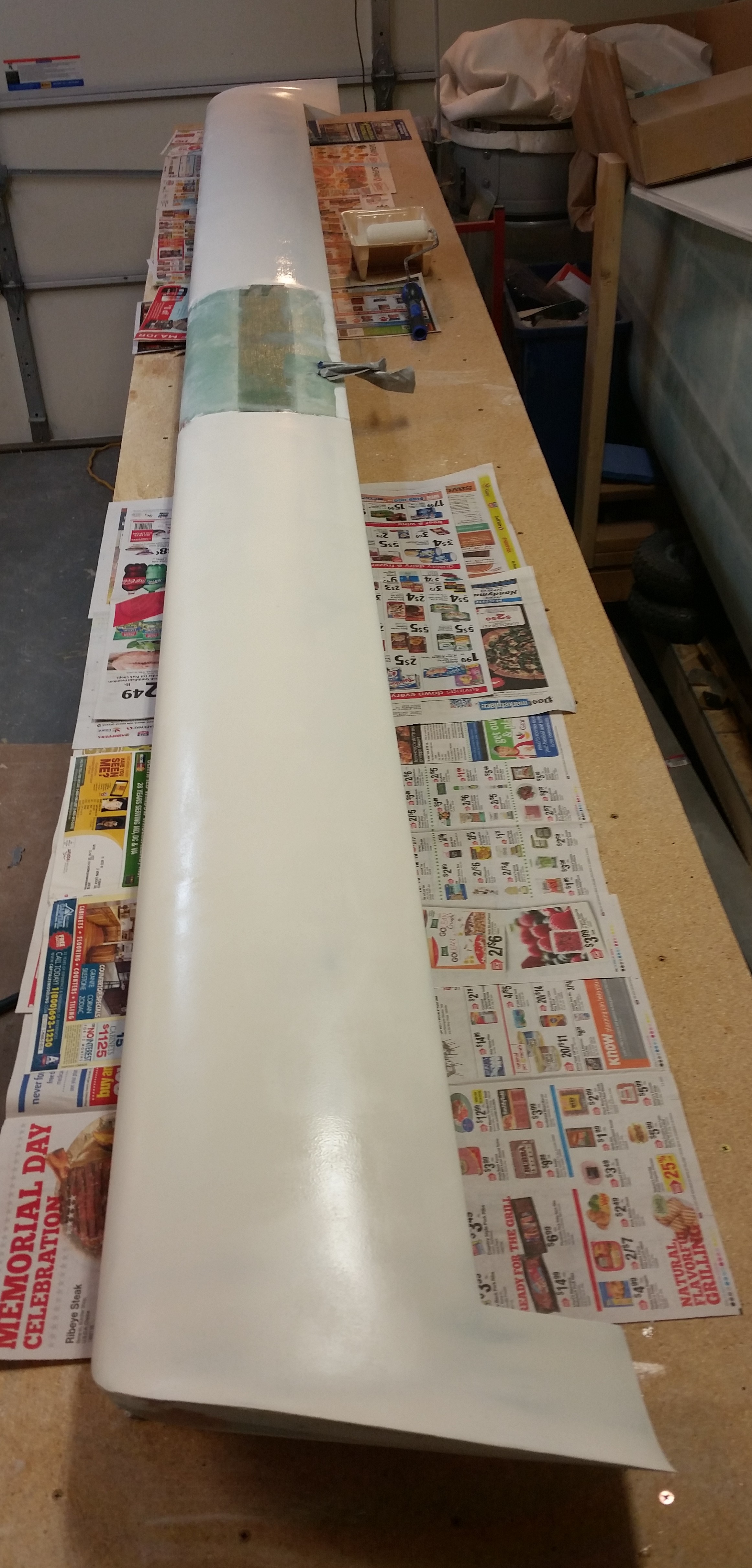
In addition, I’m going to hit the canard with another couple coats of primer of the new boat paint.  I can tell already that this new primer is much more high build than my current primer, and of course you always need a good base of primer preferably of the same brand.  In light of this, I really want to get this primer sanded down to where the canard shape is as close to final as possible, and then smoothed out even more once the new primer is applied.

Sanded primer - Round 2 of 3

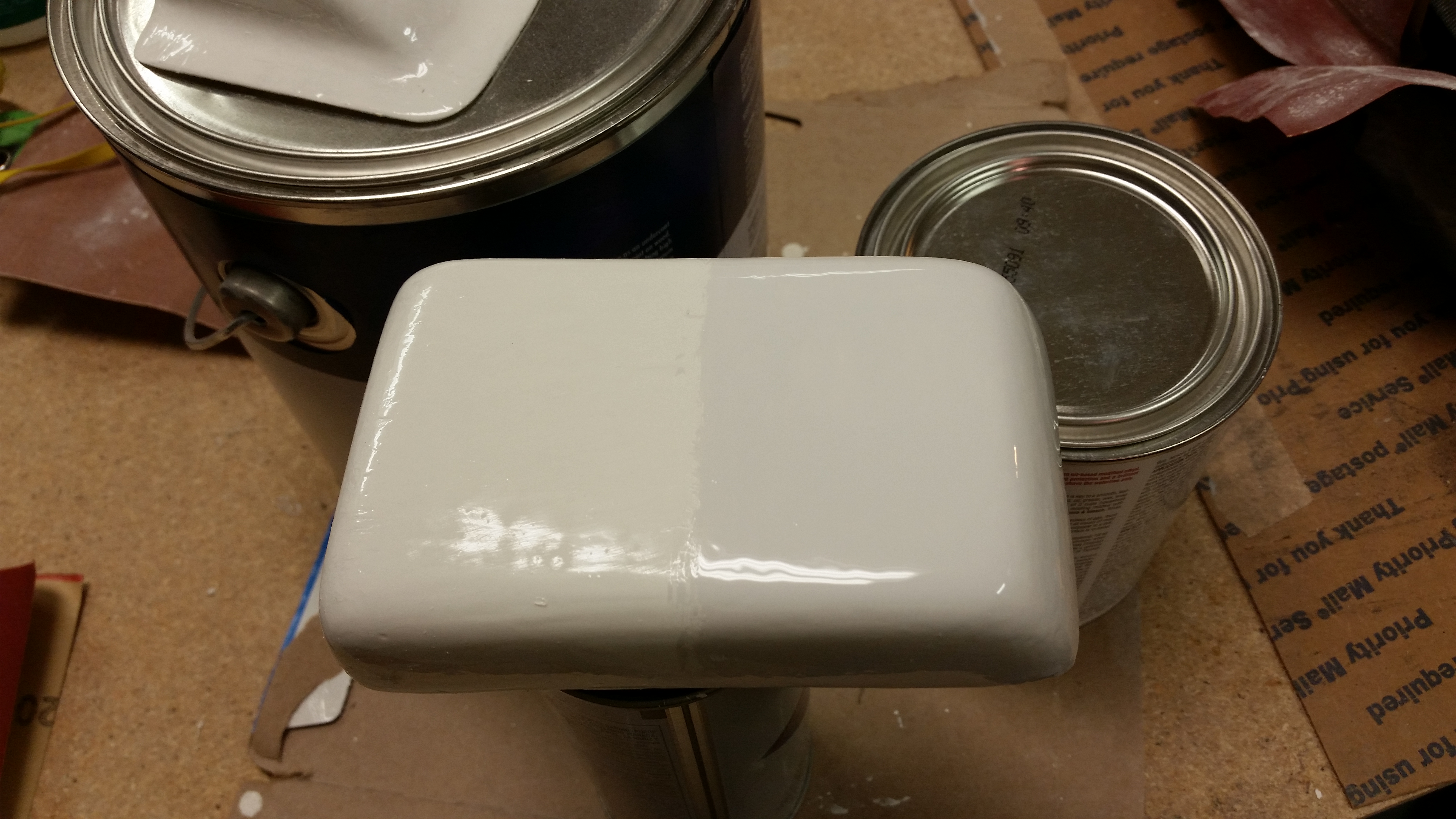
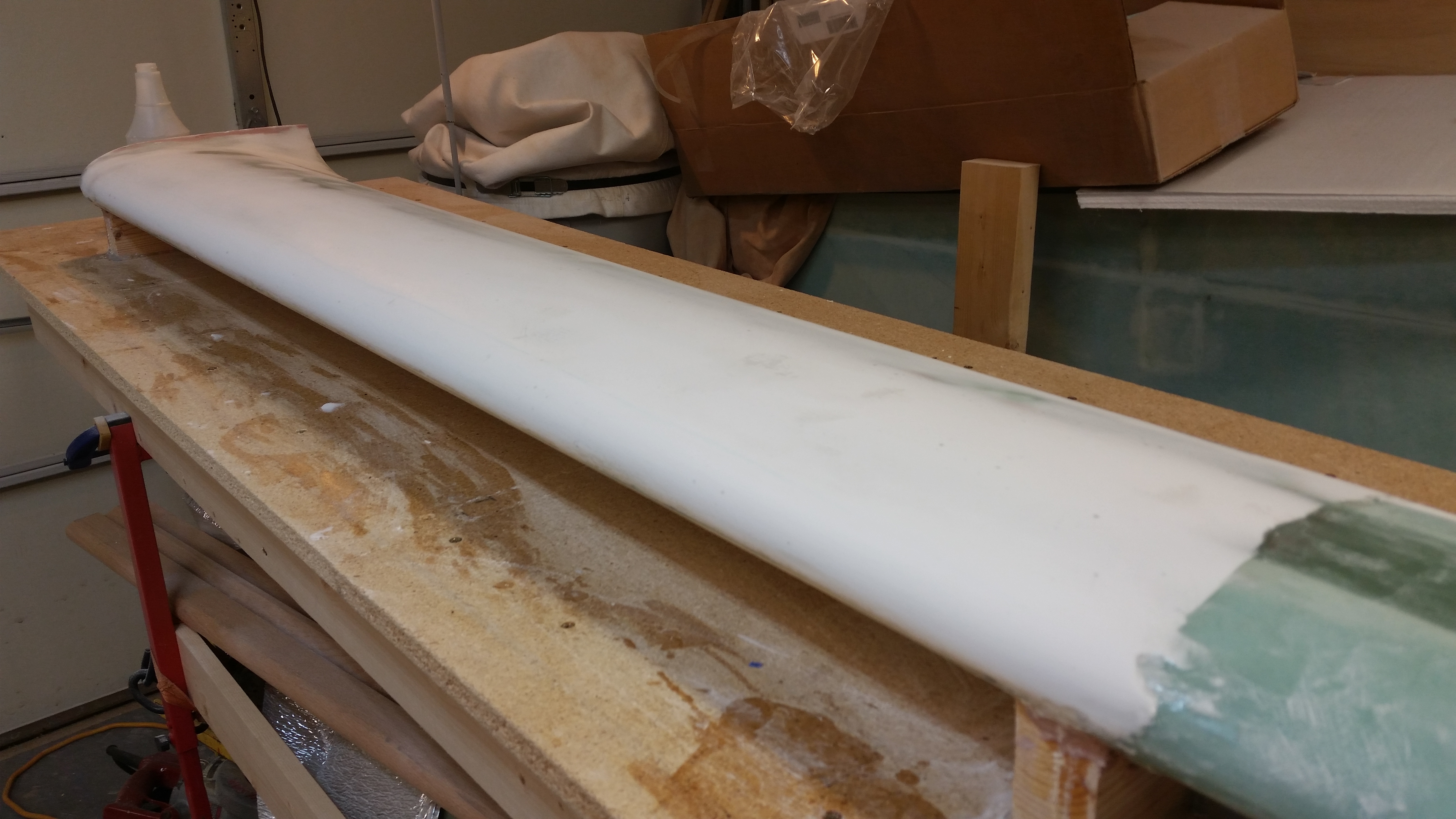
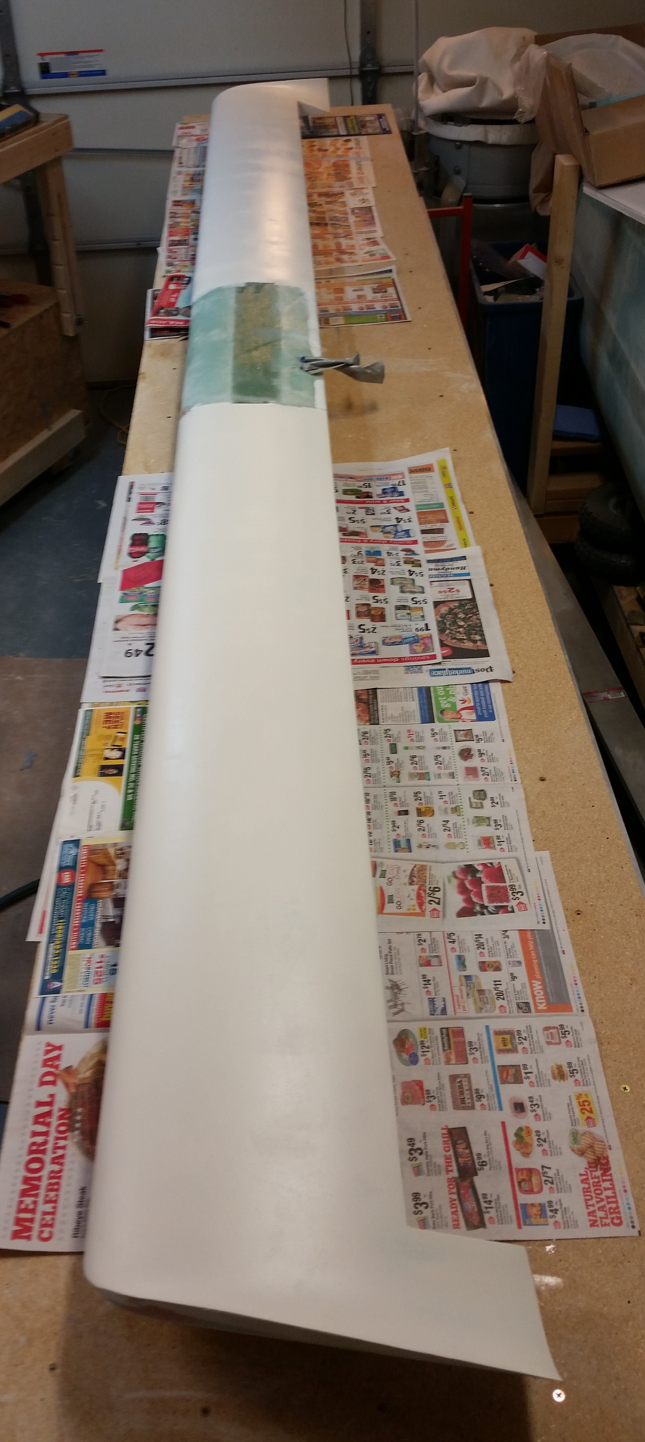
I then broke out the new paint to try it out.  As I said before as I was looking at the actual color of the white boat paint I had ordered before, in contrast with the white label on the gallon can and a standard white piece of paper, it clearly looked off white.  To compare and contrast the new paint I sanded down half of the headrest GPS antenna cover with 220 grit paper, and then painted it with the new paint.  I have to say that A) the new boat paint went on much easier and laid down much better than the old boat paint, and B) the new paint seems to have more of a “blue” hue vs a “yellow” hue, as you can see below. The bottom line is that the new paint is simply whiter, in my opinion.

New paint

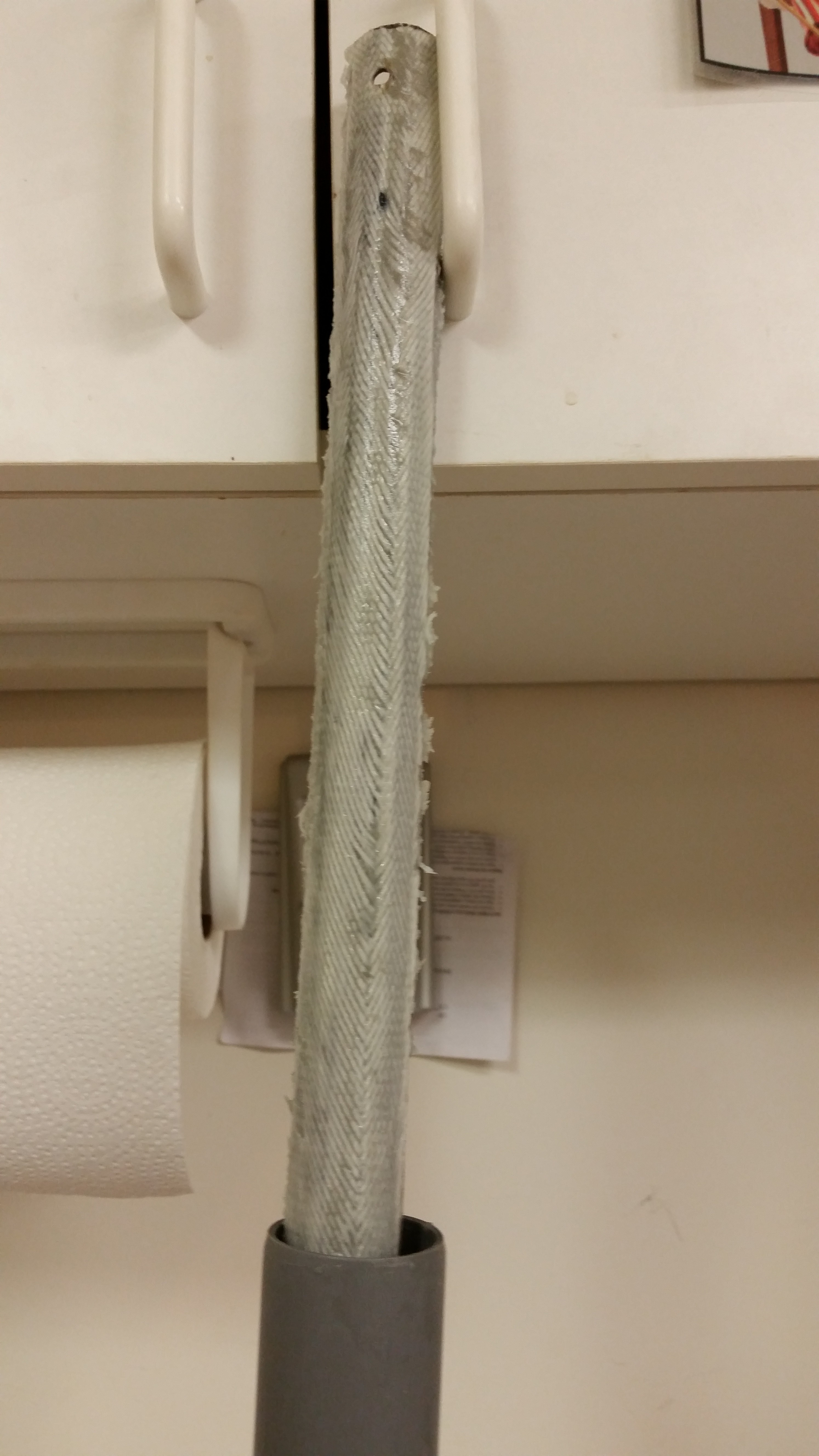
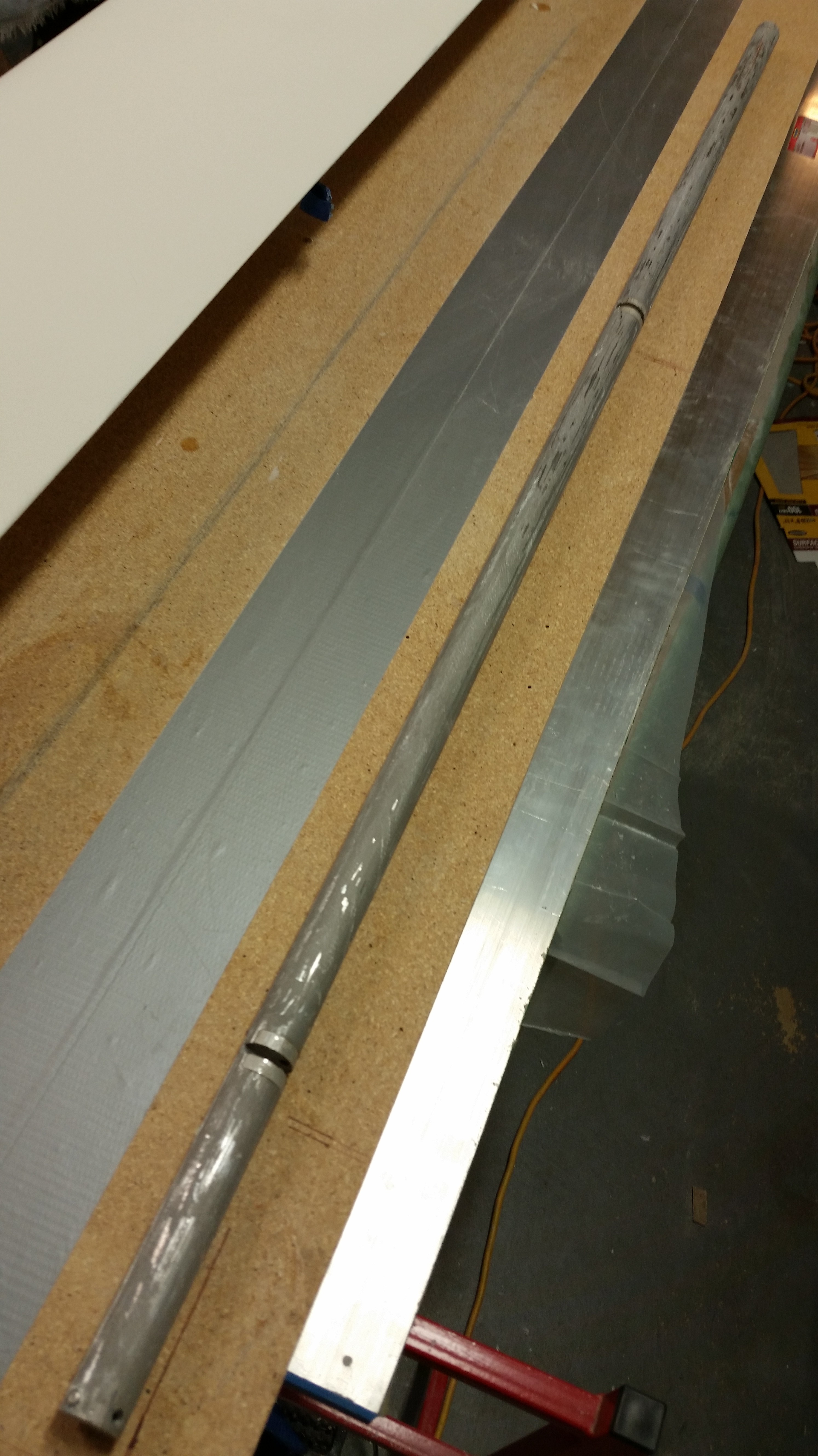
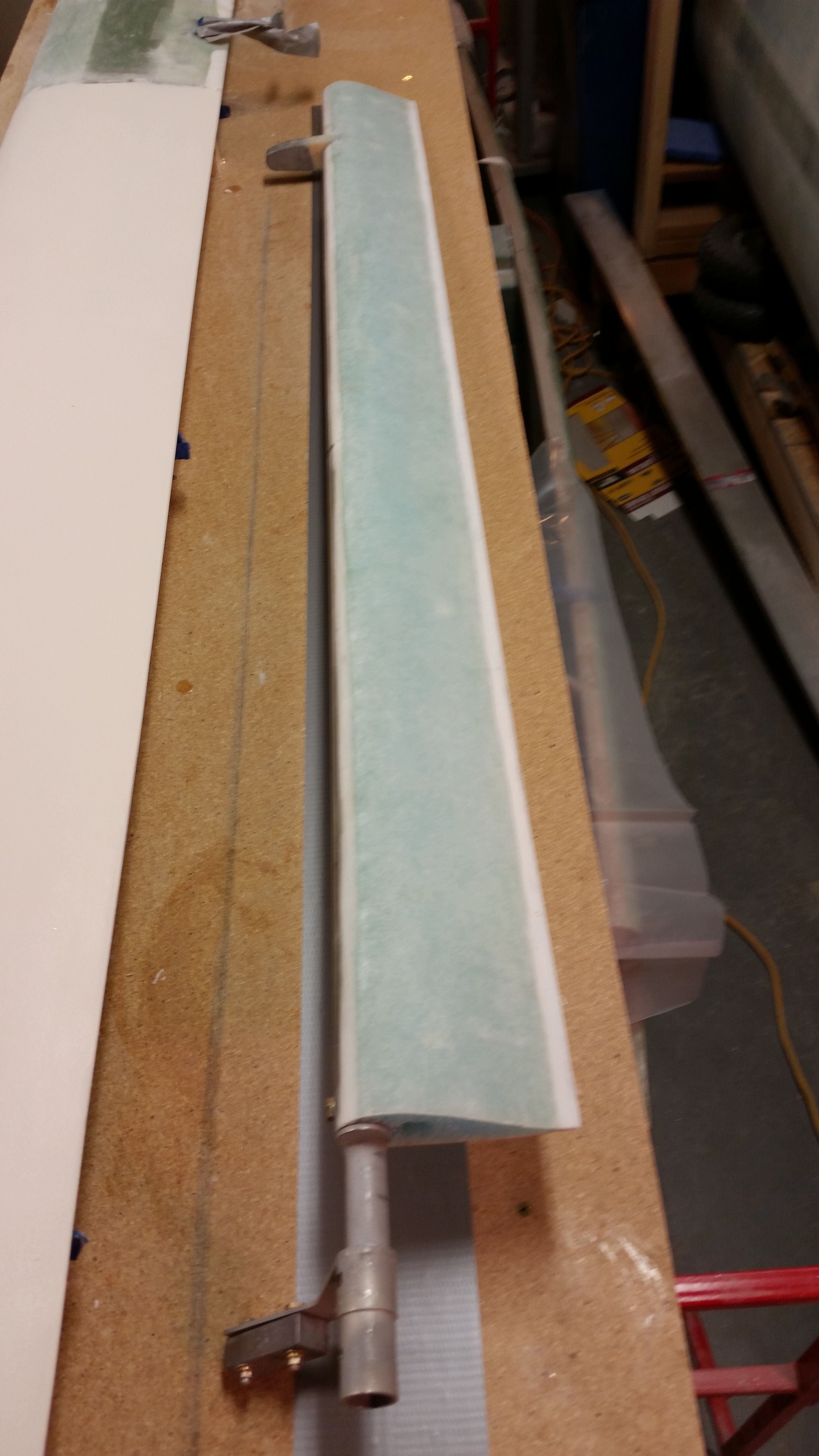
Here’s a couple shots of the elevator tube in its current state.  I would say it’s about 90% clean, and after I shot these pics I put it back in the PVC tube to soak in the vinegar over night.

Elevator tubeElevator tube

Finally, here are a couple of shots of the canard with nothing but a single light reflecting on its surface.  This provides a good view of the imperfections currently on the top surface of the canard.  As you can see, there are few minor imperfections –mainly simple & minor surface depressions– on each side of the canard top.

Canard surface view

Canard surface view

Tomorrow I plan on doing a final clean of the elevator tube, sanding down the surface, and then Alodining it in prep of micro’ing the elevator core to it.  I will also do a final sanding of the current primer on the canard top in prep of laying down a couple coats of the new primer.  I’ll then let the new primer cure 24-48 hours before giving it a final sanding.


Chapter 11 & 25 – Elevator DEconstruction

I started off spending a good hour, and 3 good long board sanding sheets, before I finally got the hint that although the primer looks cured, and feels cured to the touch, it’s not cured fully and that’s why my sanding sheets gummed up so quickly.  Argh!

So I quickly stopped that futile endeavor and started working on the elevator build prep.  My first step was to ensure the table surface was level for the elevator build.  I pulled out the über awesome aluminum straight board that I picked up in Germany to check the work bench alignment.  From the corner to about 60″ in I had just about 30 thou of sag in the table.  A couple of quick shims and everything looked good, straight and level.

Checking table surface straightness

I laid down some duct tape where the TE of the elevator will run on the table and then got to work deconstructing the elevator.

Right elevator

The first task was to remove the torque tube offset from the inboard side.

Right elevator

And then the elevator weight on the outboard side.

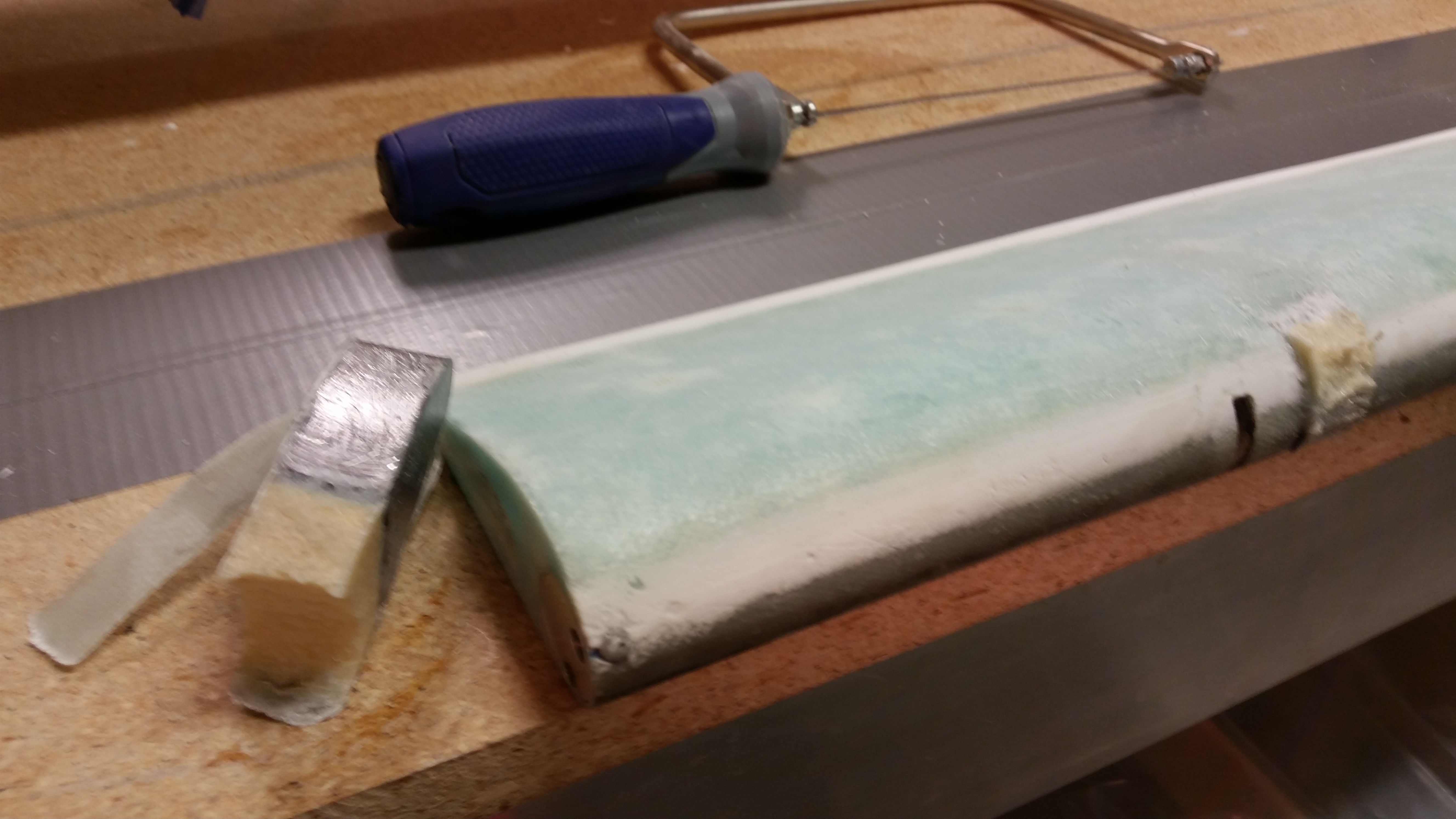
Removing outboard weight

After cutting the UNI plies at the base of the foam on top & bottom, I gave the weight a sharp rap, snapping it off.  Unfortunately it came off a little less gracefully (read: intact) than I had hoped for, but I think with some judicious application of flox it may very well work on the next elevator.  BTW, as you can see below, the UNI pretty much peeled right off the weight with a little effort, but not a lot.

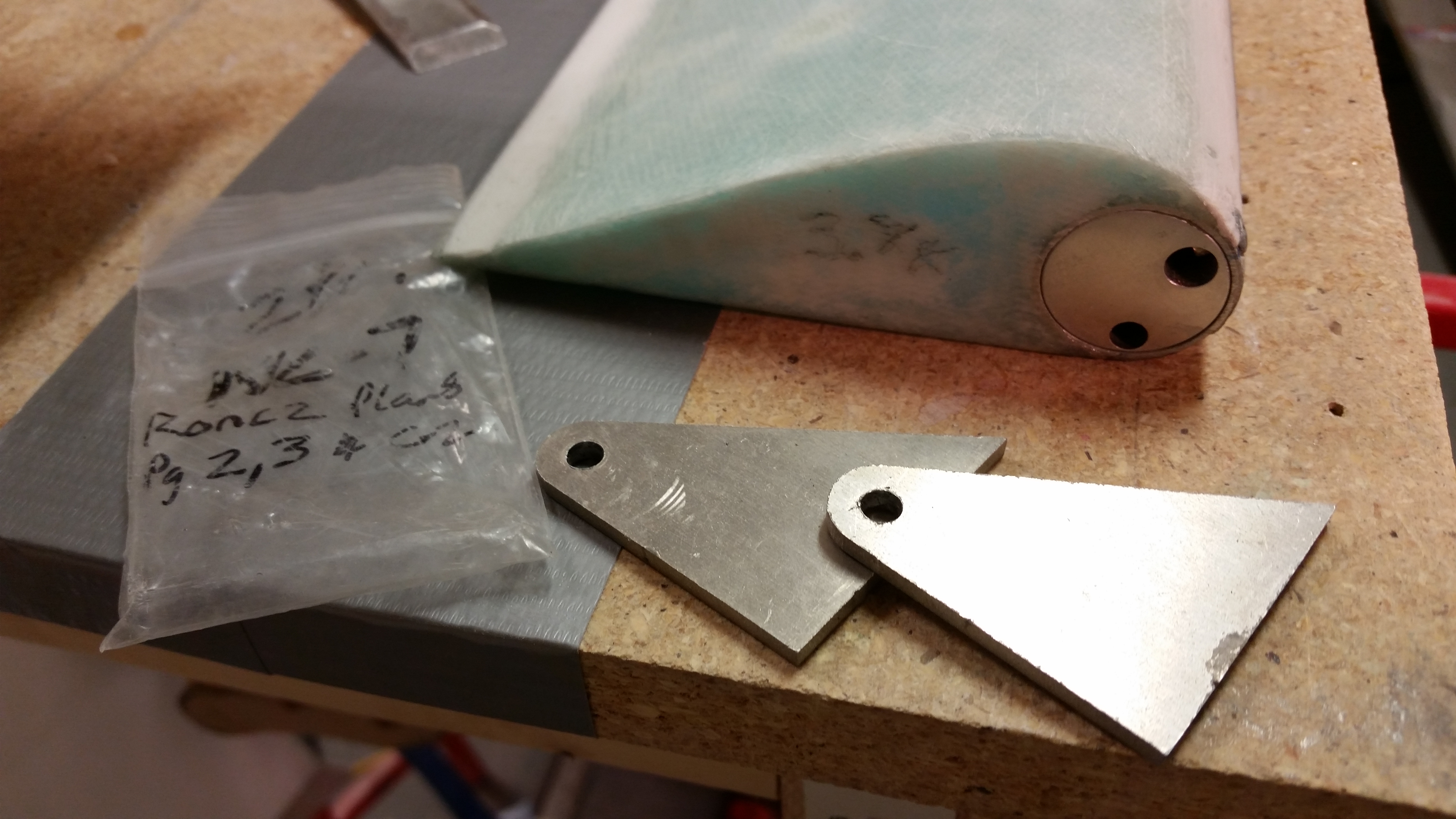
Outboard weight removed

I then broke out my old friends, the NC-7s, to get a gauge of how they line up currently in the hinge tab slots.

NC-7s . . . Again!

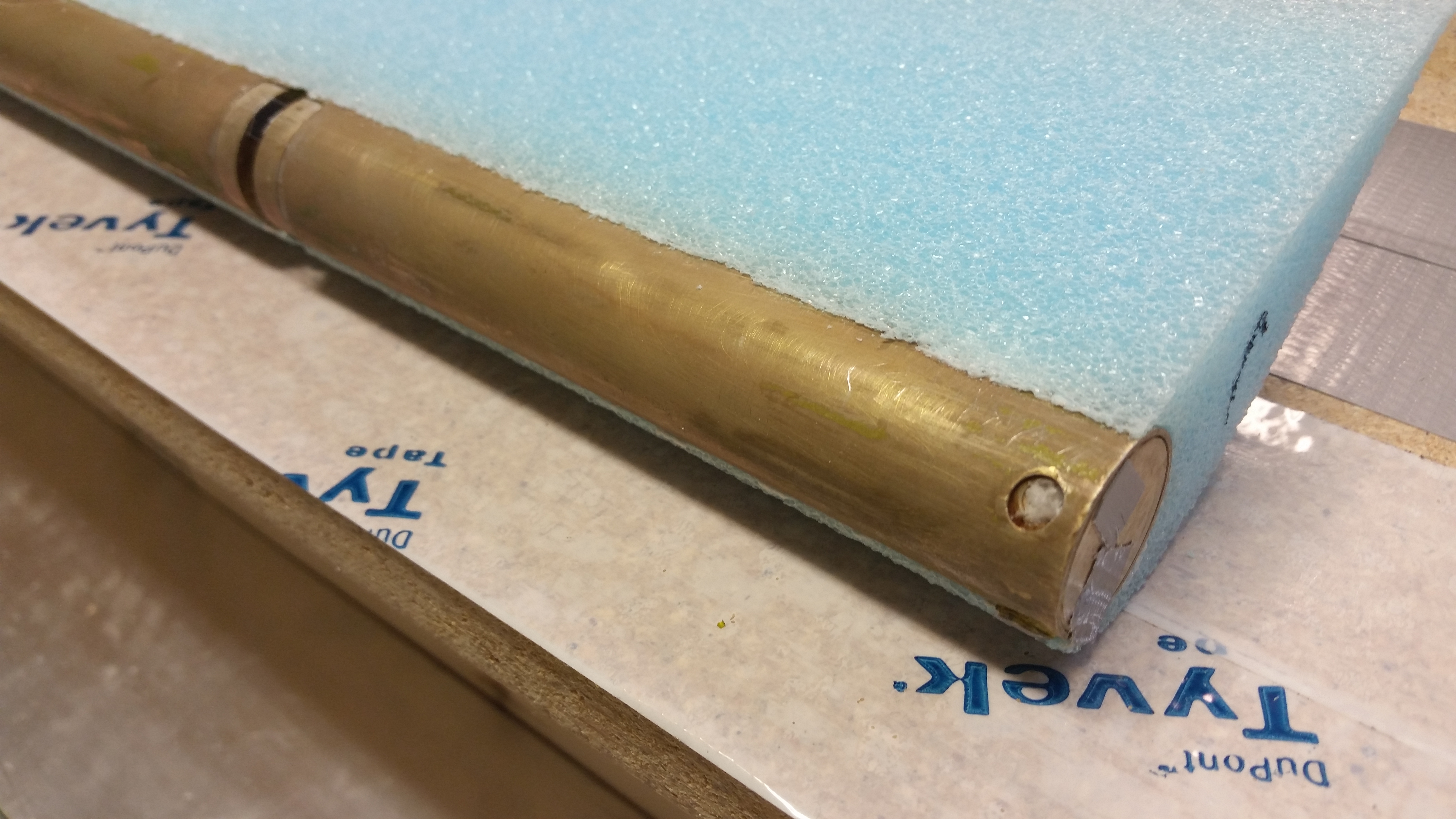
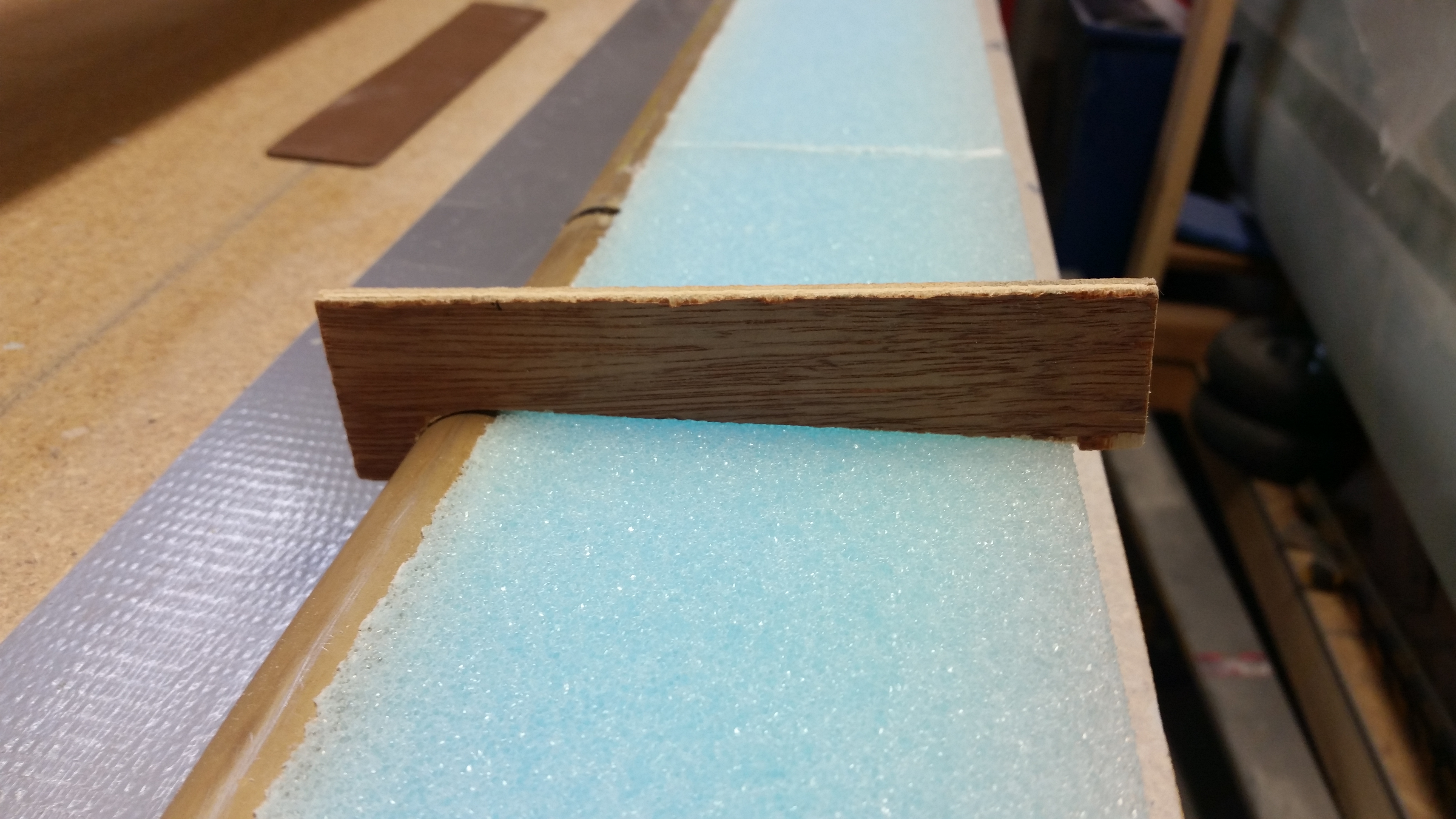
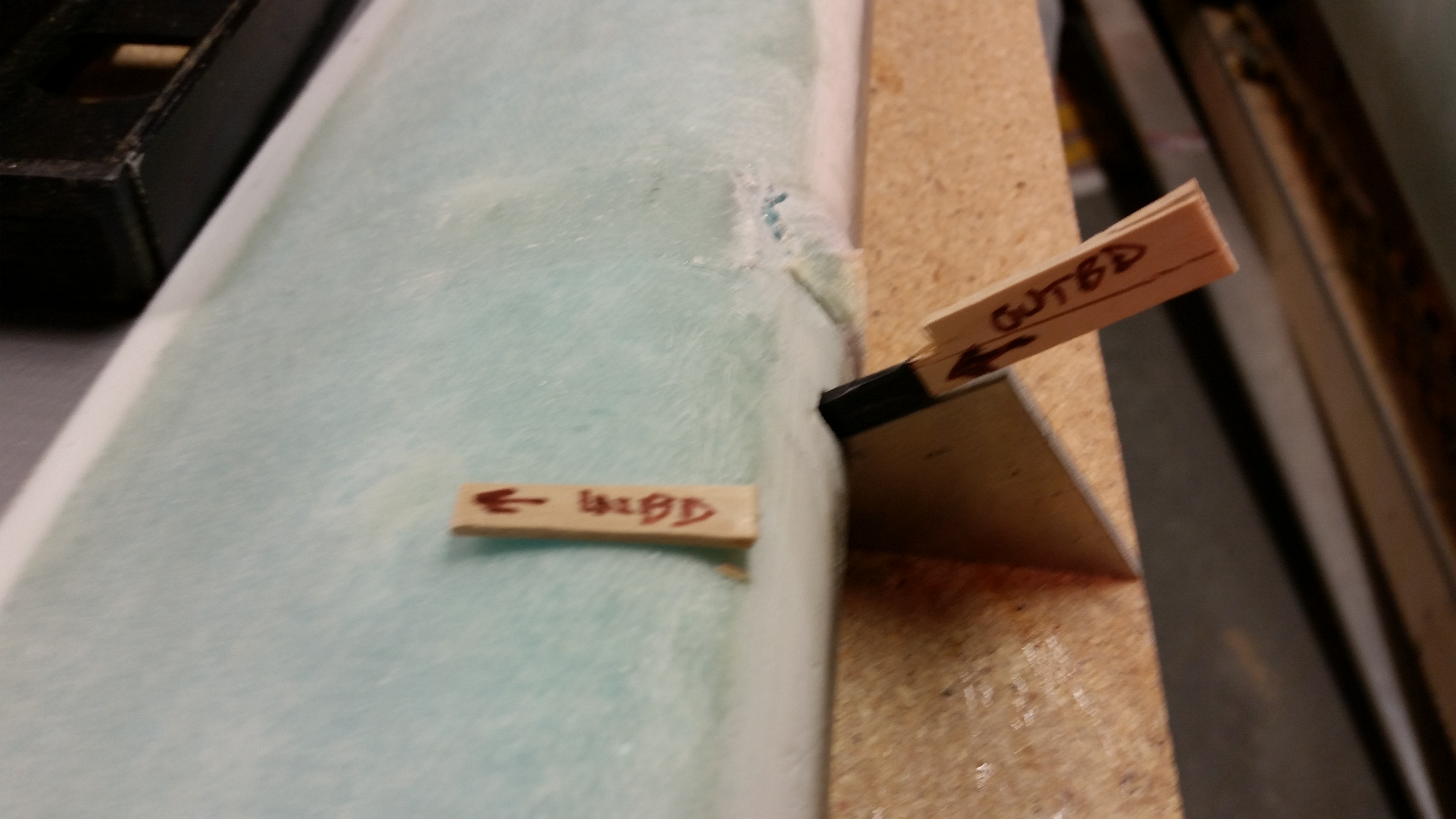
I diced up a popsicle stick to make spacers for the current NC-7 gaps to replicate this on the next elevator when the core is mounted to the tube.  And yes, I’m allowing for the .020″ that comes into play for the skin thickness.

Acquiring NC-7 spacing

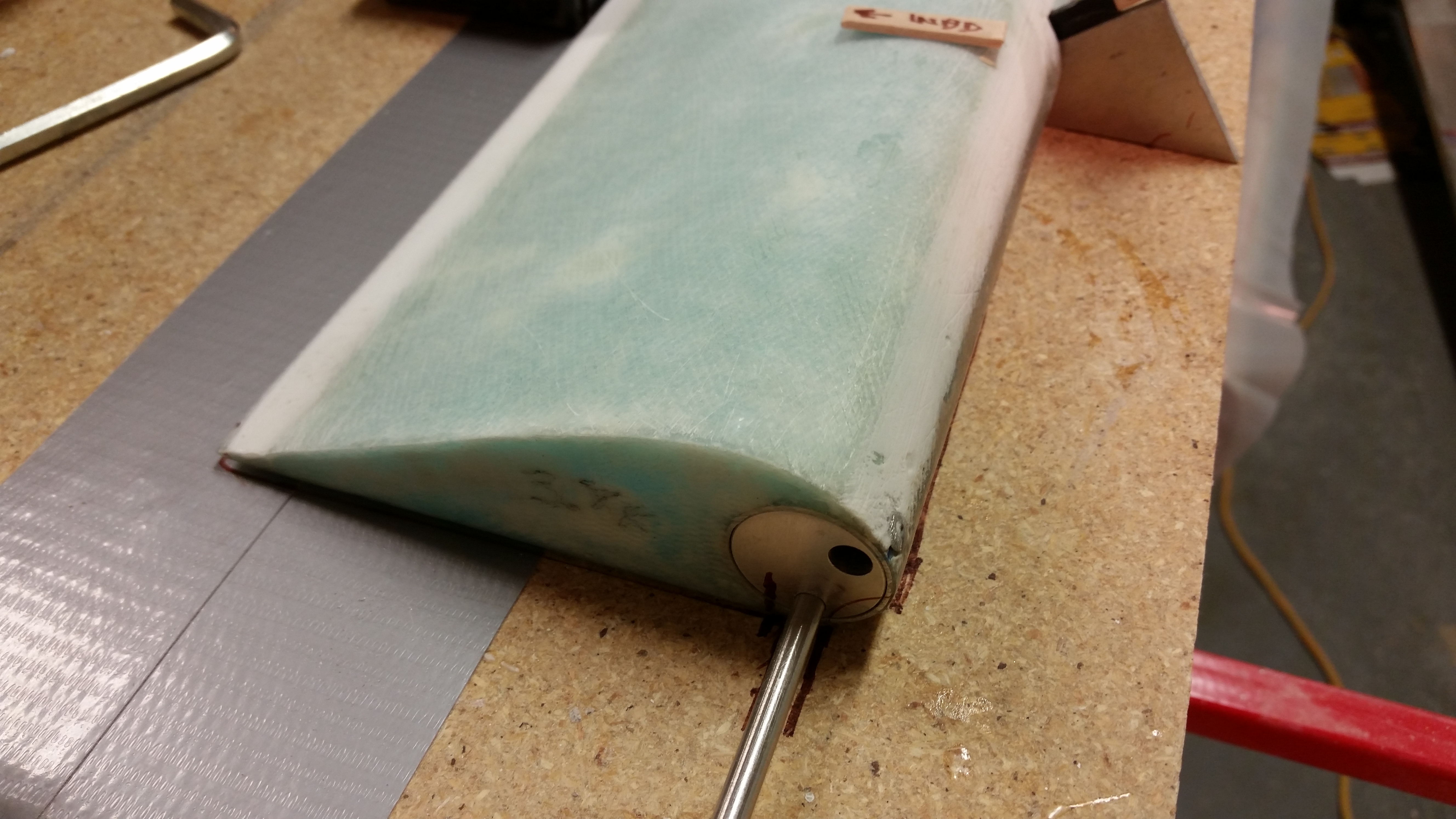
I set the current elevator in a good position for the next one as it gets constructed, and then made some alignment marks in a number of places to help ensure the elevator core gets mounted to the tube in the same configuration as the current one.

Alignment marks

This pic may be a tad fuzzy, but here is the underside of the elevator with its significant thin areas due to intense sanding over the delams that are root cause of all the issues I’ve had with this elevator.  Not good.

Surface disfigurement

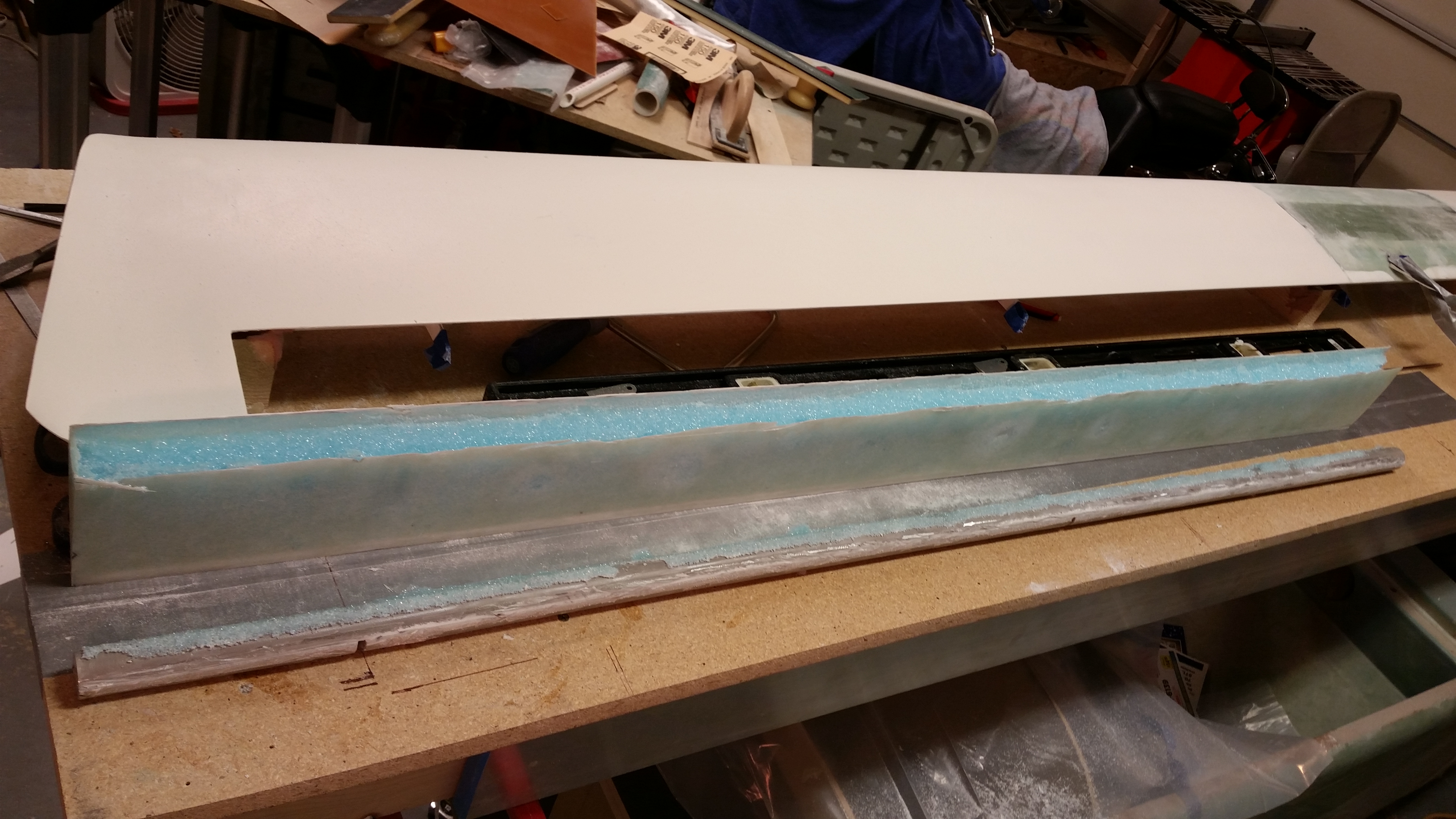
I broke out the Fein saw and started cutting right at the junction of the elevator core and the elevator tube at a very shallow angle.

Starting removal process

I would track this cut for a bit until the blade broke through the fiberglass, then was able to move forward another few inches before having to come back to the surface and start the process again.  Here is the actual cut through the skin.

Removing elevator from tube

And here’s the entire bottom side of the elevator skin cut just aft of the tube.

Removing elevator from tube

I then moved to the topside and did essentially the same thing.

Removing elevator from tube

I had to put a metal rod into the top of the elevator tube to pry it gently from the foam core, but it came off with a good amount of pressure.

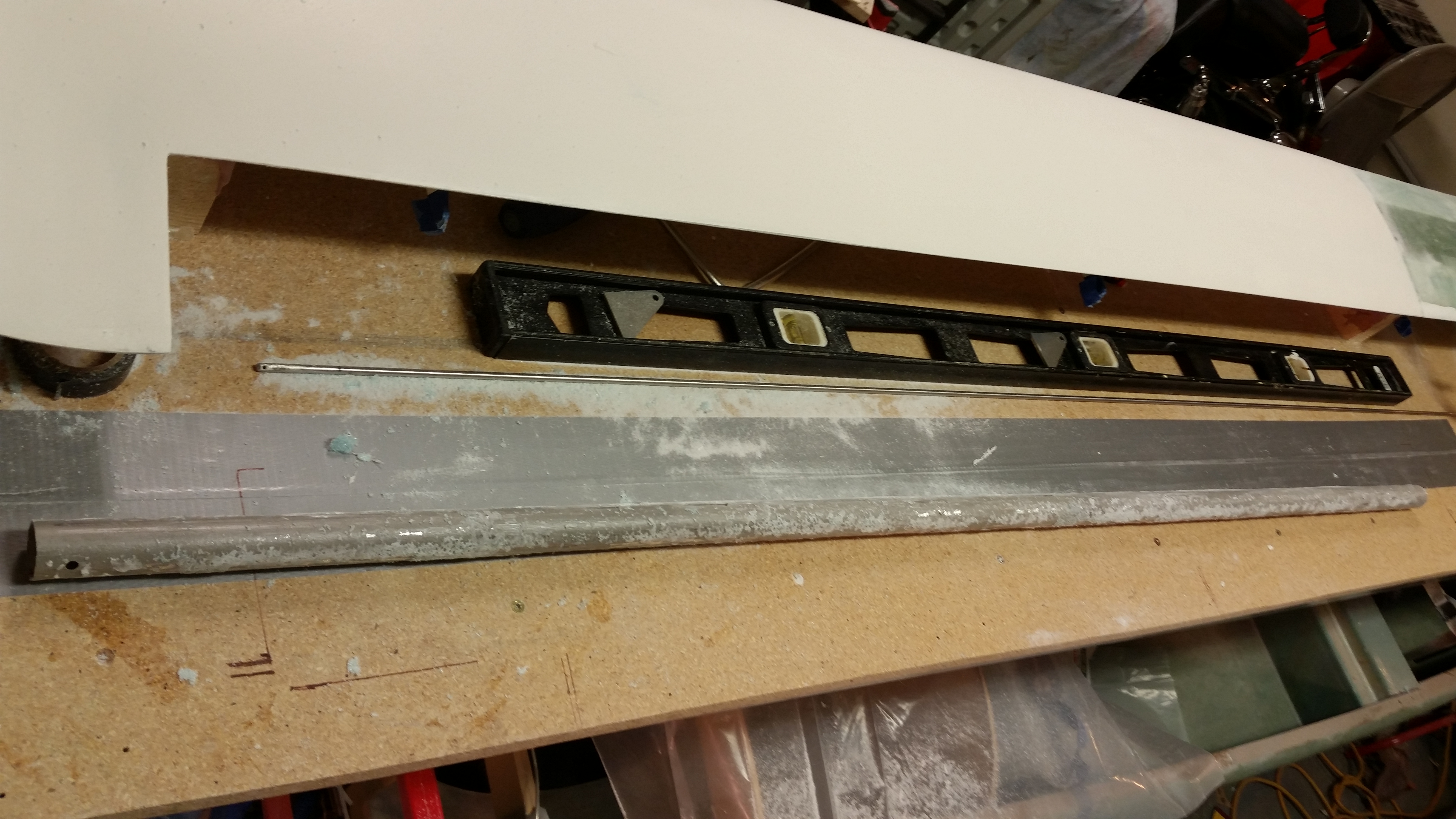
Elevator removed from tube

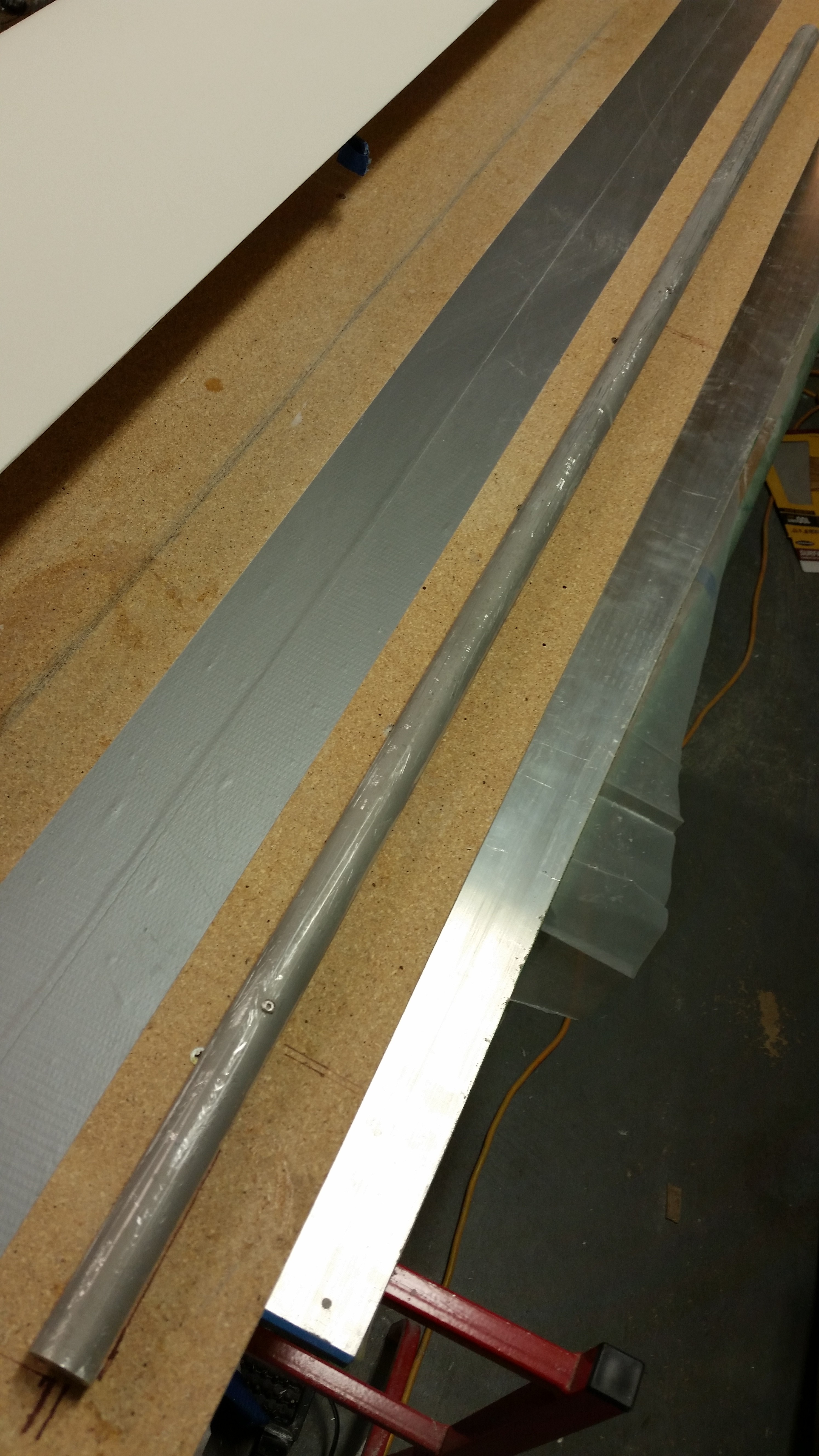
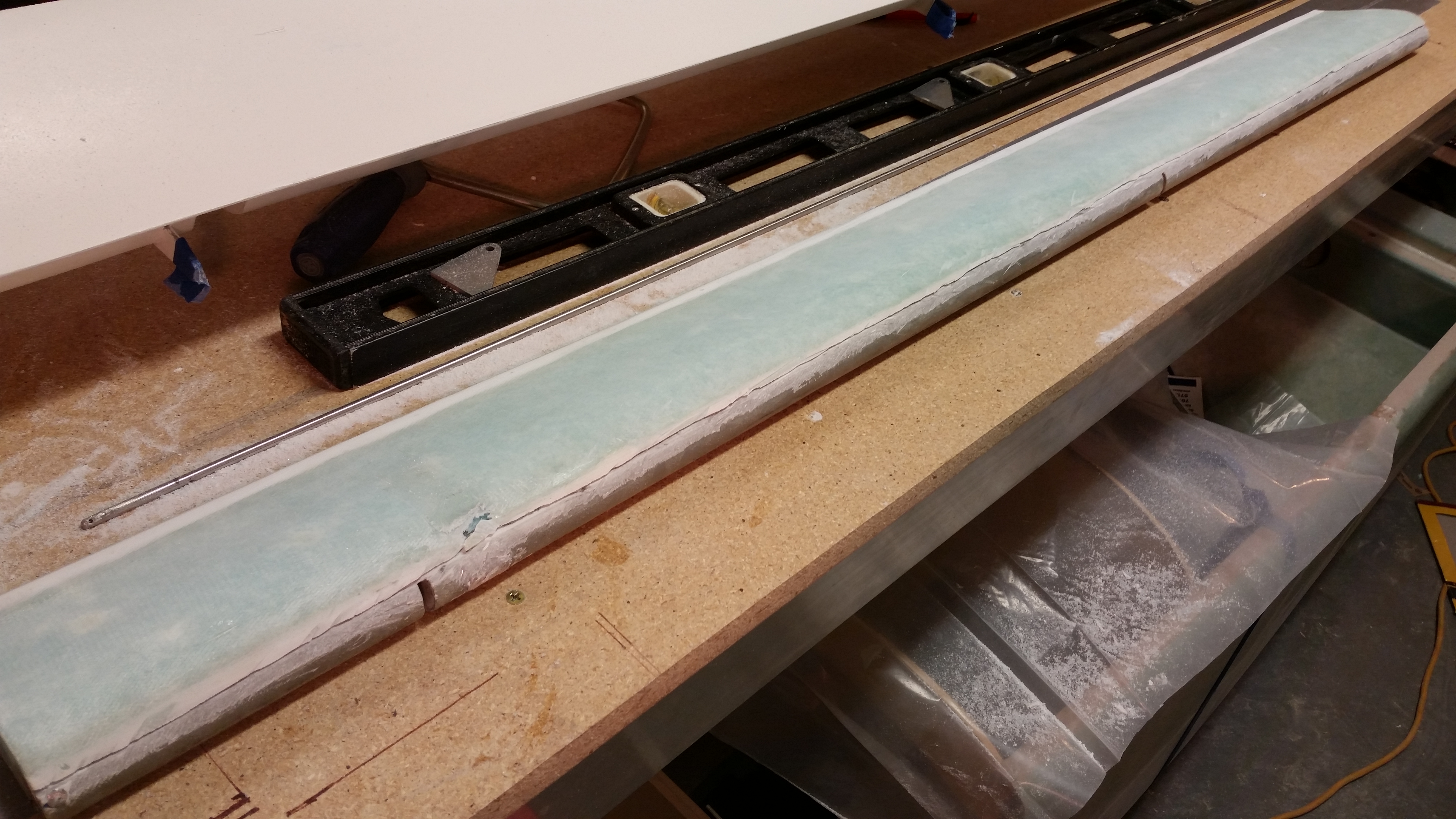
Here’s the elevator tube after I went to town on it with the Fein saw to knock off all the leftover foam, epoxy & glass residue.  I then filled up a PVC tube with white Vinegar and dunked the elevator tube into it about 3/4’s of the way up the tube (not shown).  I’ll let that sit overnight and see if it softens up the goobers on the elevator tube.

Tube after initial cleanup

Tomorrow I’ll continue my quest in finishing this new elevator, and the final sanding of the primer on the canard.


Chapter 13 & 25 – Rock the Casbah!

Or rather the canard!

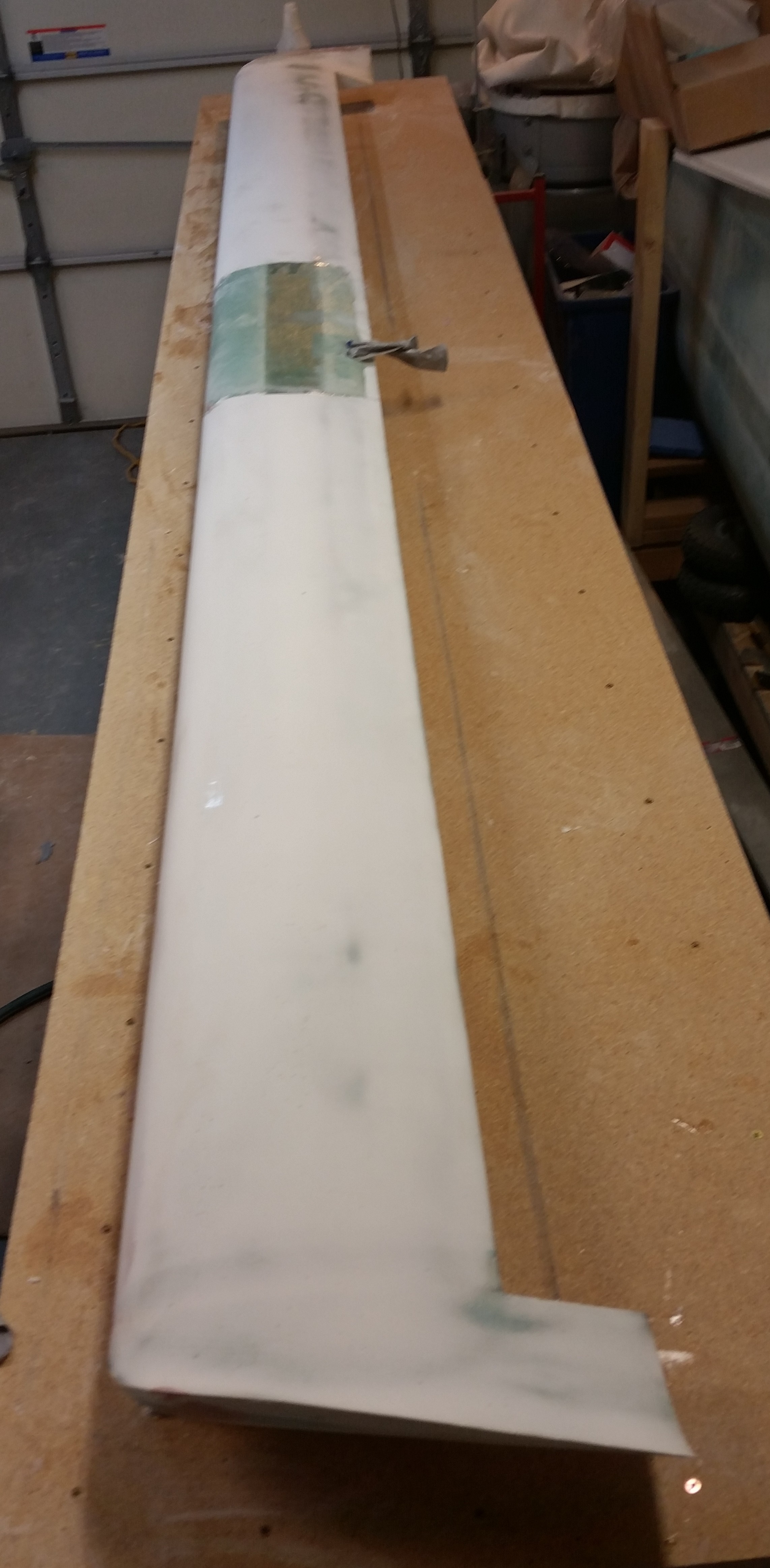
I started out today by sanding the pure epoxy coat on the topside of the canard.  I began with 120 grit on the long board in a 45° pattern, both to the left and to the right.  After I sanded both sides with the long board, I then switched to 220 grit and wet sanded the epoxy finish.  This helped get the lower lying areas that should get filled with the high build primer.

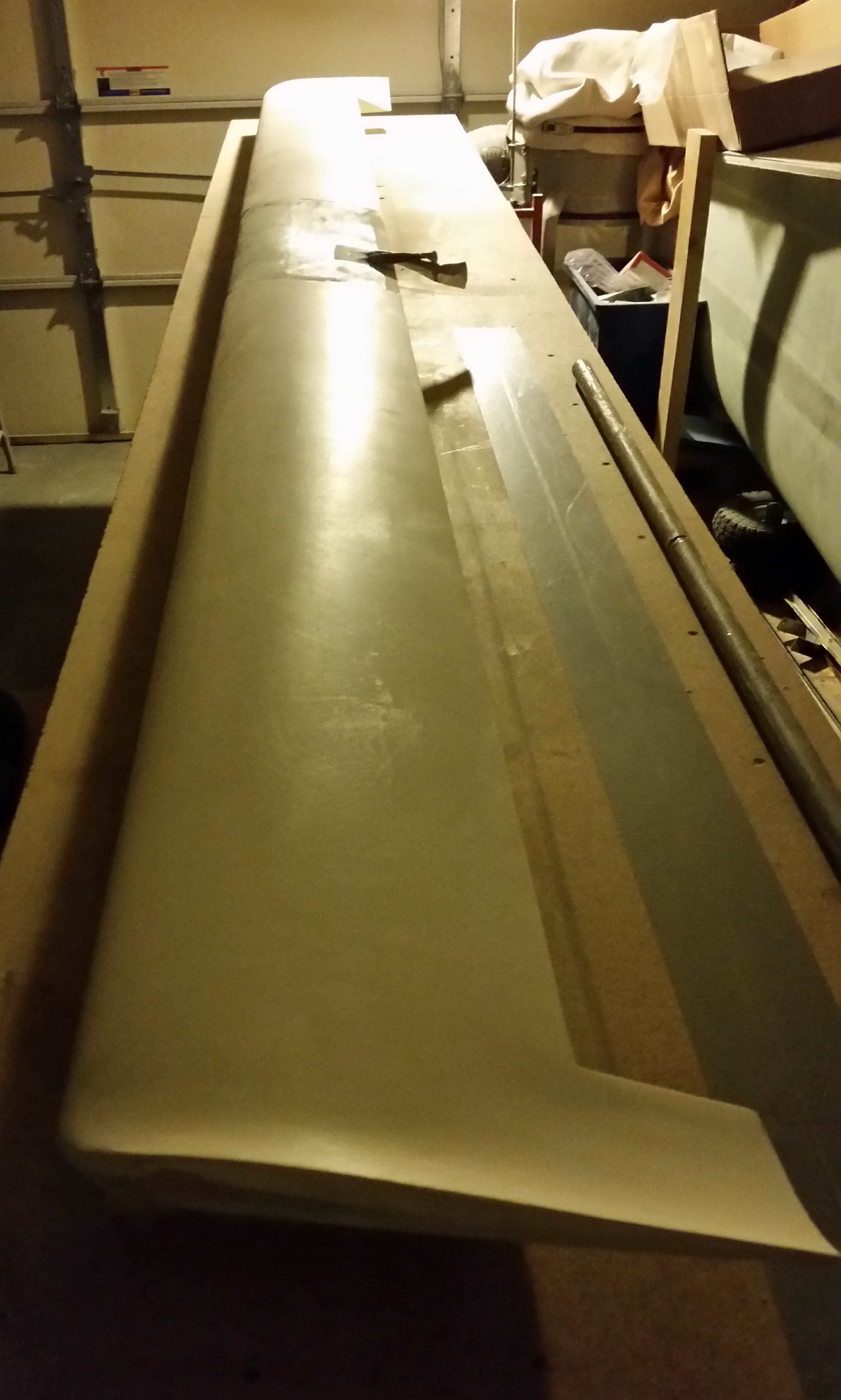
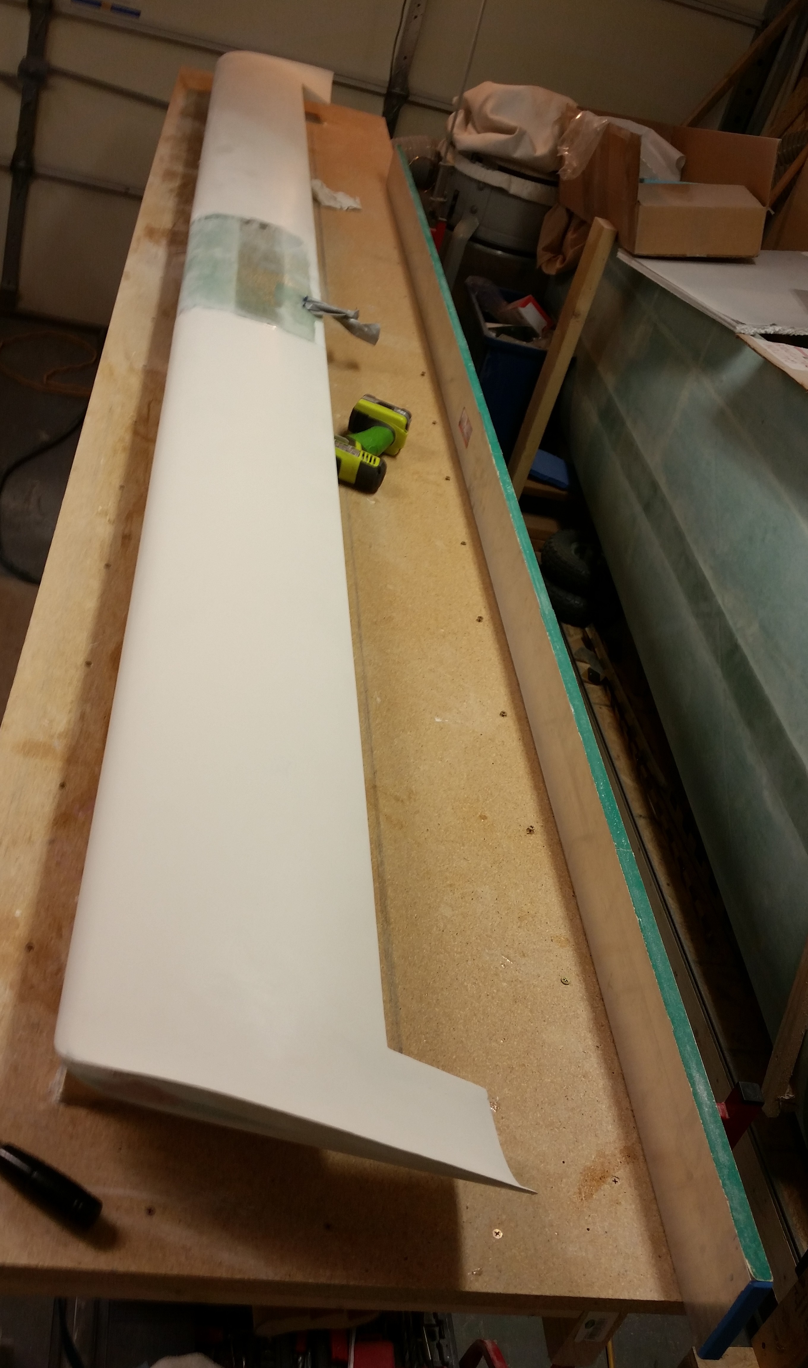
Sanded down canard top

Here’s a shot of the right side.  For some reason the blog didn’t like the left side pic since I couldn’t load it.  Needless to say, it looked about the same.

Sanded down canard top

I then applied primer to the canard.  The shot below to the left is the first coat, and the right is the second coat.

First coat of primer

Second coat primer

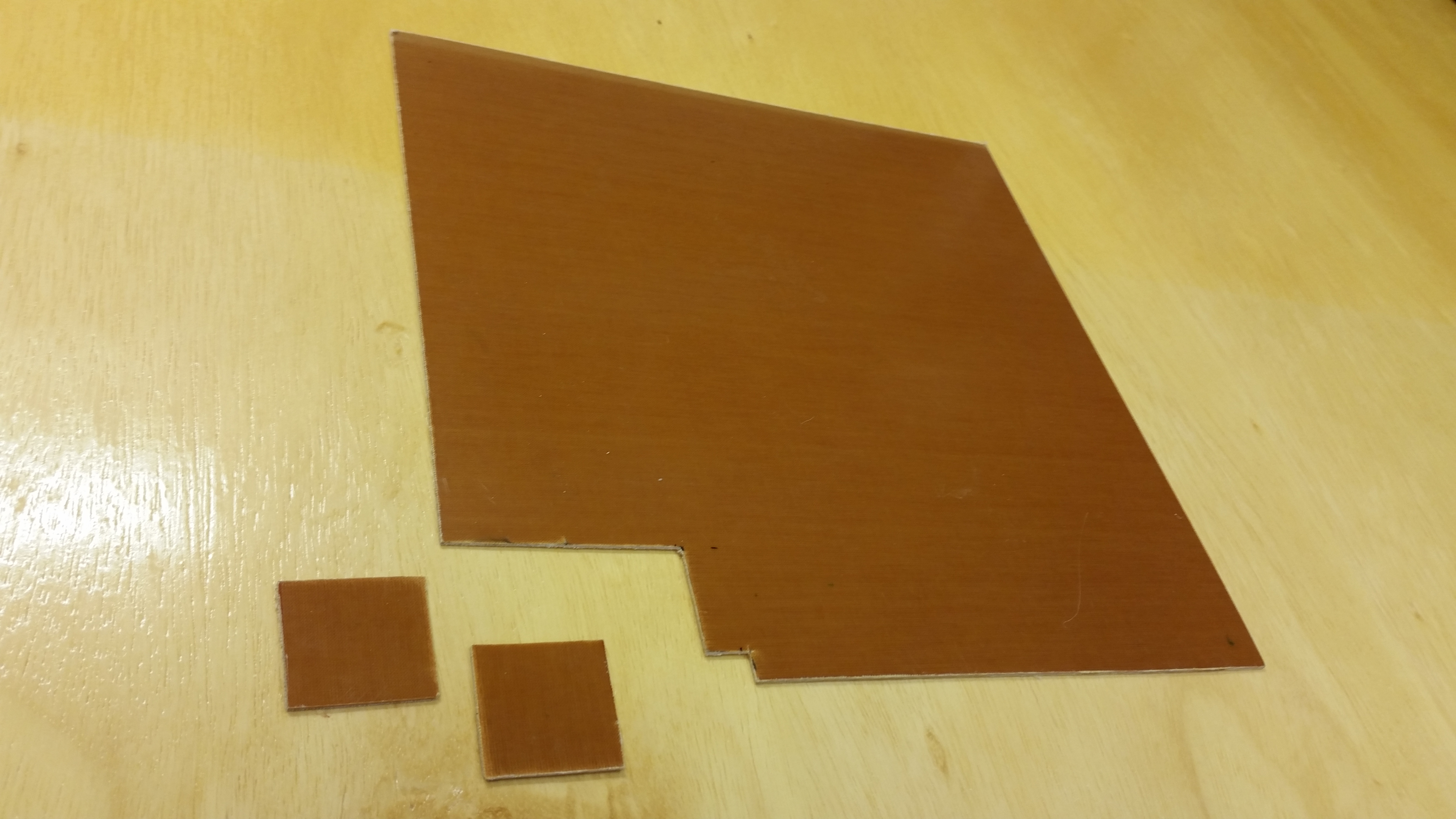
In between priming the top of the canard, and watching football, I cut out the 2 phenolic support pieces that will be embedded in the NG30 cover for the AMP CPC connectors.

1/16" phenolic for gear actuator connectors

I also cut the 8 pieces of UNI for the new elevators that I will be rebuilding here in the next week.

UNI cut for new elevators build

In total I added 3 coats of primer.  I’ll wait until its cured tomorrow to block sand it.

Also, as I was prepping the canard for primer I happen to really note the color of the boat paint on the headrest GPS antenna cover and the ice shields.  It’s not a bright white, as the primer is not, so I’ll be calling Jamestown Distributors this week to figure out the way ahead on that.  I want the white on my bird to be as white as possible… not the 1970’s dull off-white stuff.  So I’ll be evaluating the paint further as I move forward.


Chapters 13 & 22 – More Electrical Stuff

Today –while the canard epoxy cures– was about research and getting reacquainted with my electrical system.  My specific interest was in figuring out what components, electrical & otherwise, that I was going to put into the nose.

Now I know a lot of my contemporary building buddies would whip up some awesome looking CAD diagram with exact dimensions down to 3 decimal places that looks like an engineer’s dream, but me being a former military “Powerpoint Ranger” and certified neanderthal, I simply added a slide depicting my thoughts on this matter onto the end of my ongoing notes for the nose build.

Again, this stuff is really just a mental thought jogger on what will most likely go into what areas in the nose, and get me thinking if there is any pre-actions or prep I can do as I build the nose.  Some of the components I ID’d will be in the nose area, but aft of F22: OAT probe, static ports, buss fuse housings, etc.  In addition, on many of the components I had to look up in my notes, emails, websites, install manuals, etc. to either confirm or research further why and how they were getting installed where.

Nose components

Now, I mentioned CAD earlier, so speaking of CAD:  The CAD program I was using to create my electrical diagrams was NanoCAD, as recommended by Bob Nuckolls in the AeroElectric Connection online forum.  This was a great CAD program for electrical diagrams primarily because A) it was what Bob used to create all of them, and B) it was FREE!  Unfortunately, my version of NanoCAD is no longer supported and apparently NanoCAD is now on Version 7, which costs a decent amount of money now to buy.

Well, no worries since I have TurboCAD, which I happened to purchase while I was in Tampa, Florida.  But I didn’t have it loaded up on my desktop so I ended up spending a good half hour loading up TurboCAD and familiarizing myself with its features before I could open up any of my electrical diagrams.  Why? Well, in a series of typical events, I had taken all the hardcopy printouts of my electrical diagrams down to my buddy Marco’s house while I was on leave from Qatar in March 2014, forgot them there, and haven’t been back to retrieve them yet . . . mainly because every time I go to visit him he puts me to work building HIS Long-EZ!  HA!  (Click here for the real story . . . )

Thus, to be able to make my annotations on my electrical diagrams on an actual sheet of paper, I had to be able to open the darn files to print them, which I am happy to report that I am now able to do.

In line with my reviewing my nose electrical components, my main preparation is in getting the nose gear actuator wiring sorted out to test it.  I had planned on going over all my electrical stuff today since the epoxy was still curing on the canard and also, in part, because my AMP CPC connector order from Mouser was scheduled to be delivered today, which it was.

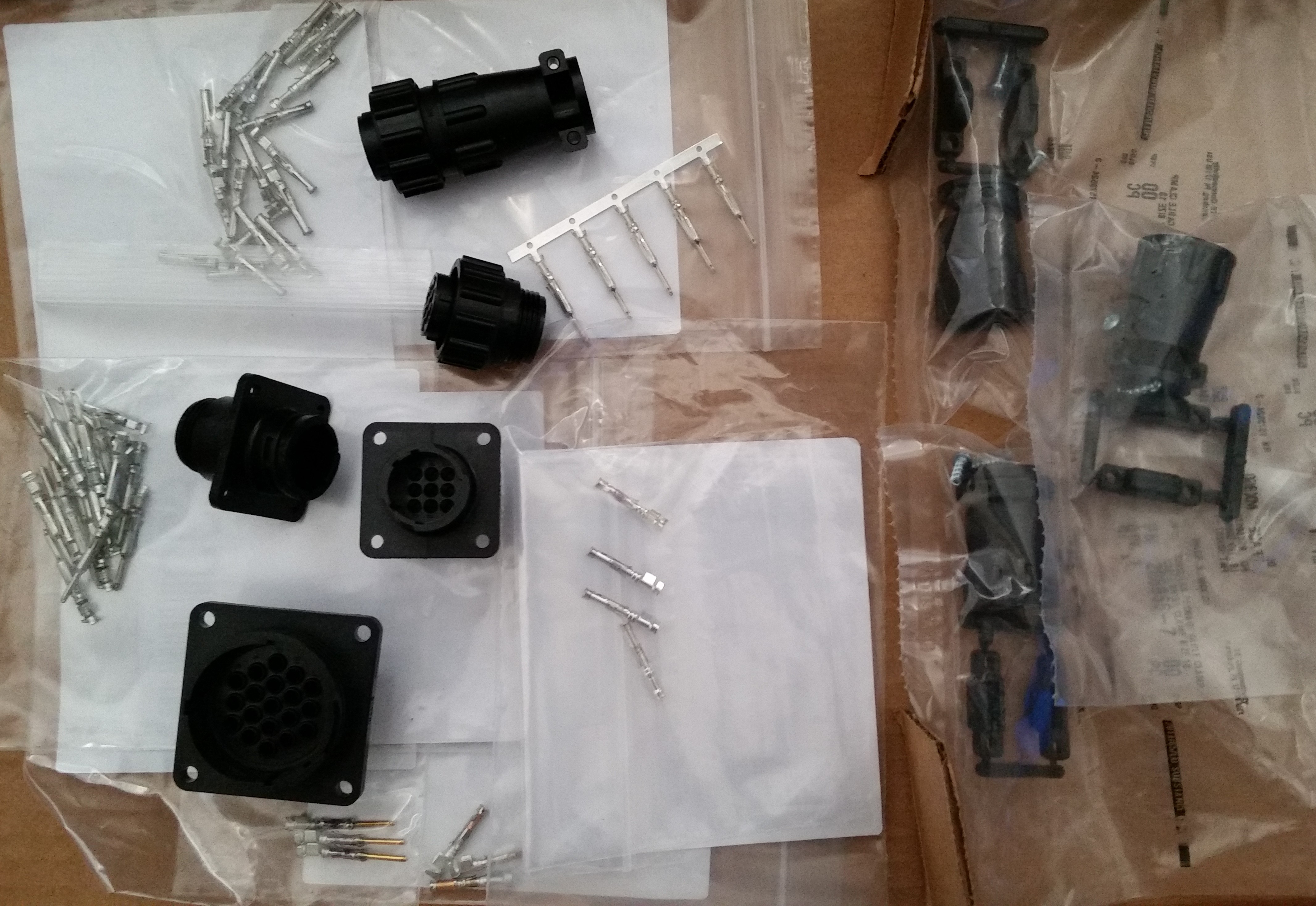
I checked out all the goodies from Mouser and pretty much solidified my plan for the wiring & connections for the nose gear actuator system.

AMP CPC electrical connectors

Tomorrow I plan on a good final sanding of the canard top surface before I apply a couple of coats of primer on it.  In addition, I’ll most likely cut the UNI for the elevators and start planning out a refined elevator build schedule.  Who knows, I may even get the nose gear actuator wired up & tested out.