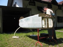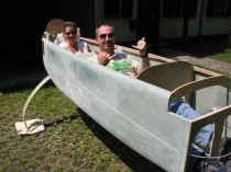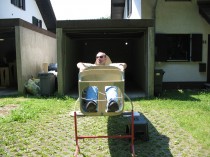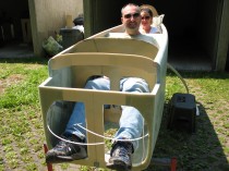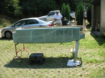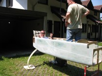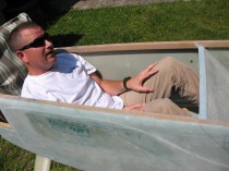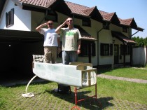
Fuselage/Gear Mockup & Wing Build

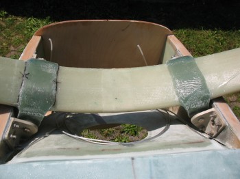
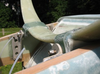
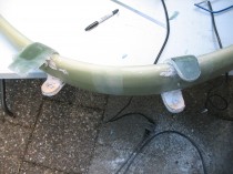
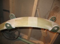
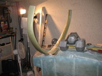
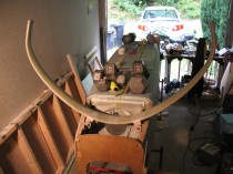
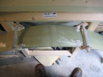
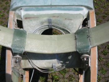
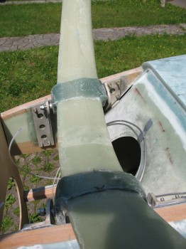
I final knife cut & sanded out the main landing gear tabs.  Then I took the gear outside & mounted it to the fuselage… it fit! (Whew!)

I then measured the respective gear legs to the “nose” centerline mark.  One side was 0.2″ closer to the CL mark than the other … oh well, I’ll mitigate that when I mount the axles.
Chap 9 - Gear MockupChap 9 - Gear MockupChap 9 - Gear MockupChap 9 - Gear Mockup

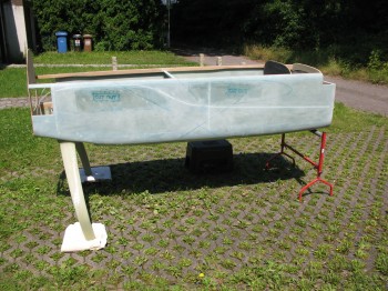
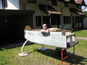
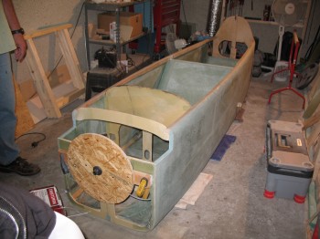
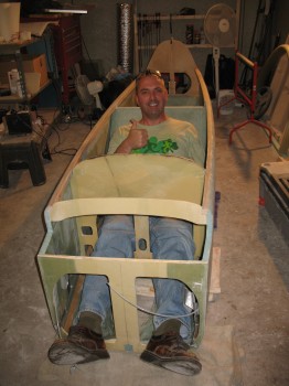
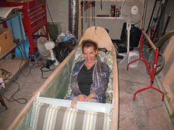
I tightened up the gear bolts & flipped the fuselage over so it was sitting on the gear.  It looked good!
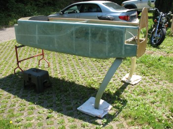
Fuselage & Gear MockupFuselage & Gear MockupFuselage & Gear Mockup

I then hooked the battery up & tried out the landing brake in some what of a more “operational” setting!

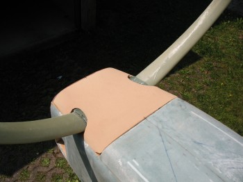
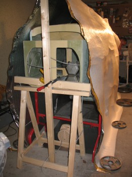
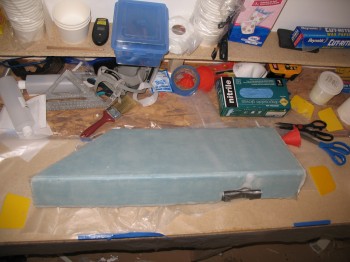
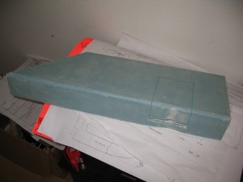
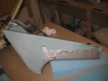
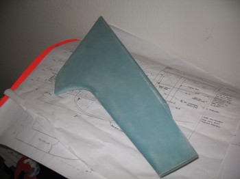
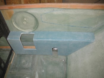
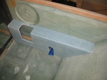
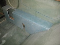
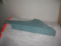
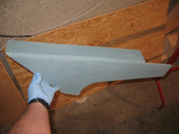
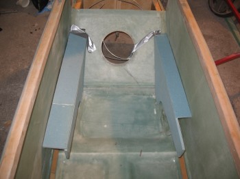
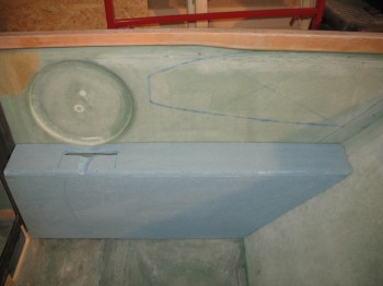
And finally, before I put the fuselage away in storage, I played around with some urethane foam & cut/shaped a hellhole cover… kind of a pain.  But good experience.
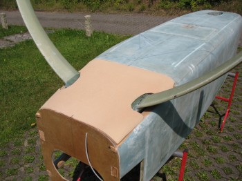
Chap 24 - Hellhole CoverChap 24 - Hellhole Cover

After I put the fuselage away in its climate controlled storage facility (my dining room!), I did the final aligning, measuring & mounting of the wing jigs to the wing base… which was fairly time consuming to make sure the jigs were perfectly aligned, square, parallel, perpendicular . . . etc.
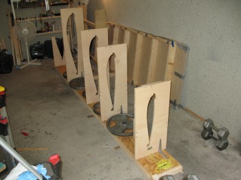
Chapter 19 - Wing Build

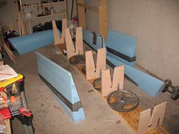
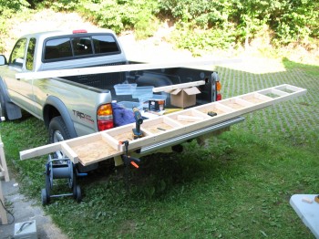
With the help of Gina & Kevin, I pulled out the Right wing cores, spread them on the portable workbench outside, and aligned them all together.
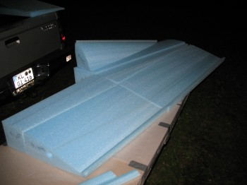
Chapter 19 - Wing Build

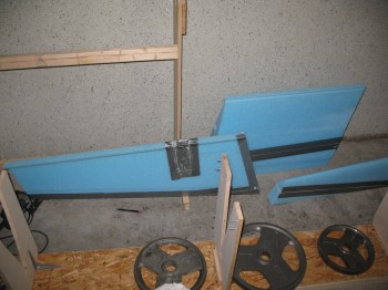
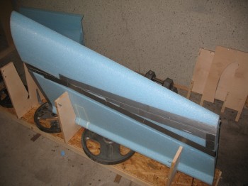
After duct-taping the foam edges to protect the foam as much as possible from stray wayward micro, we micro’d the core pieces together (FC1, FC2, FC3, FC5) and set them in the garage to fully cure.  I should point out that there are 5 major sections of  wing cores that make up the wing.  Starting at the rear of the wing, on the inboard side (nearest the fuselage) is where the counting starts.  The back half of the wing has 3 major sections:  FC1 (INBD), FC2 (Middle), and FC3 (OUTBD).  The front half of the wing only has two major sections, and it actually starts in the middle of the wing (since the strake makes up what constitutes the “Inboard” wing) and moves outboard.  The front major sections are FC4 (Middle) and FC5 (OUTBD).  Hopefully this will help put things in context whilst discussing wing core sections.
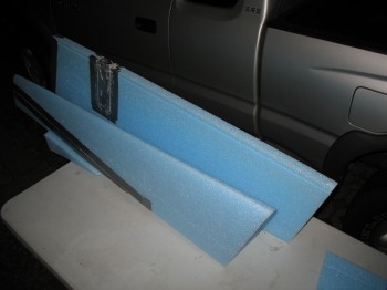
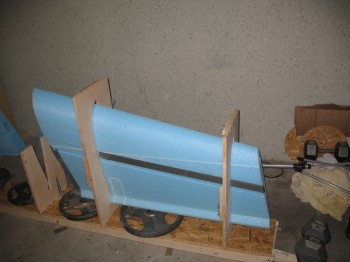
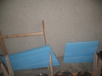
IMG_0024Chapter 19 - Wing BuildChapter 19 - Wing BuildChapter 19 - Wing BuildAfter the micro started setting up, I very carefully slid the first core segment into the wood wing jigs.  I set the front wing half core on top of the rear wing half as you can see in the pic above.  [This was just for testing the fit & picture purposes.  The front wing core was not micro’d to the rear wing core at this point].  Since the micro was drying, we removed all the tape before it became a permanent part of the wing makeup (micro is some tough stuff… especially with tape!).
Chapter 19 - Wing BuildChapter 19 - Wing Build


Chap 9 – Final Main Gear Build!

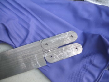
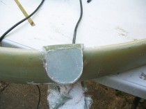
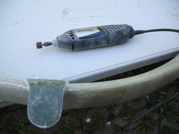
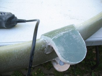
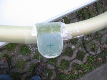
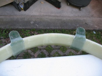
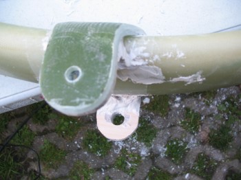
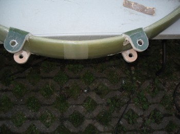
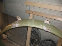
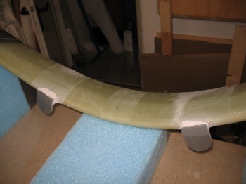
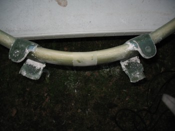
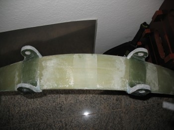
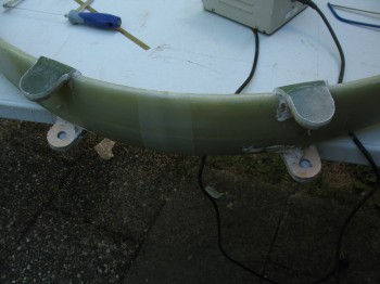
I hand sanded the landing gear tabs & used the Perma-Grit tools to create a beveled edge at the tab-to-gear bow junction.

Chapter 9 - Main Landing Gear

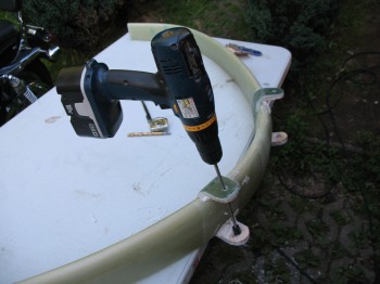
I used the small round Perma-Grit to again re-bore & open the land gear tube holes.

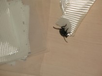
I once again had a friendly visitor stop by… he hung around for a little while and then went on his way (with some assistance!).
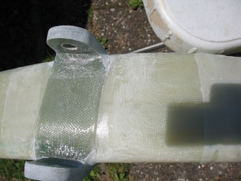
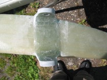
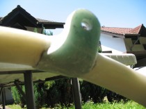
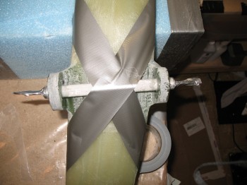
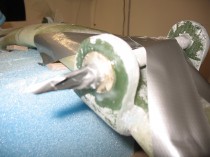
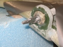
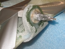
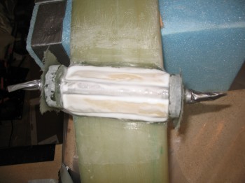
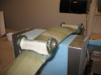
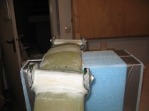
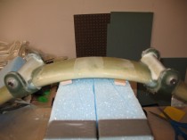
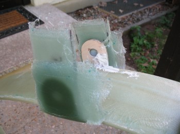
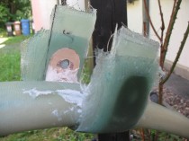
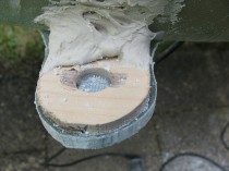
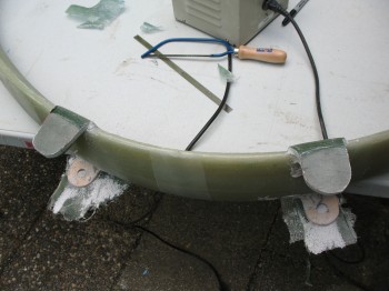
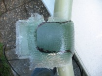
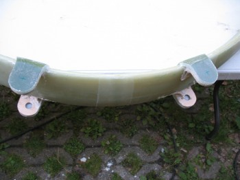
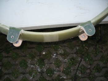
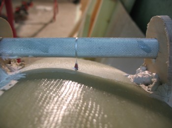
I mounted the steel landing gear tubes into place with flox, then immediately floxed & glassed large AN washers onto the outside of the tabs with 2-ply BID layups.

Chapter 9 - Main Landing Gear

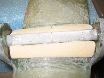
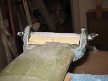
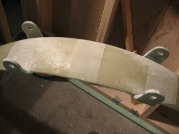
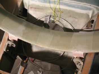
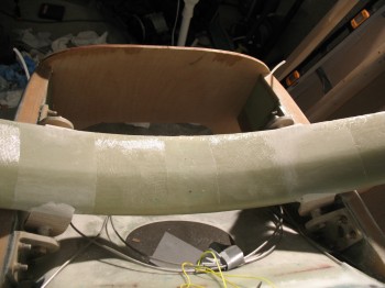
I then carved foam wedges as “ramps” for the landing gear tubes & micro’d them into place.  I then covered the micro’d ramps with 2-ply BID layups.  These ramps allow for glass to hold the steel tubes in place, but still have a smooth transition to the base of the landing gear bow.

Chapter 9 - Main Landing GearChapter 9 - Main Landing GearChapter 9 - Main Landing GearChapter 9 - Main Landing Gear

In between the drying stages above, I knife edged all the new tab edges.

Since the main landing gear glass was complete, I turned my attention to the wing build.  My first task was a 5-ply test layup for the 3″ UNI tape that is used in the wing, CS spar and canard spar caps.  Over the years there have been different manufacturers & suppliers of this 3″ UNI tape, so to ensure the spar caps are the correct thickness, and thus the correct strength, the width of the UNI plies must be tested.  This test layup procedure is spelled out in the Canard Pusher (CP) newsletter #25 on page 6.  If the 5 plies are too thin, then the solution is to simply add more plies, which is also spelled out in the CPs.

CP 25 pg 6 - 5-ply spar cap thickness testAs my 5-ply test layup was curing, I went back out to the shop and finished mounting my wing jigs to the wood base.

Chap 19 - Wing Jigs


Aluminum, Post Cure, Wings & Gear

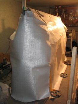
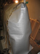
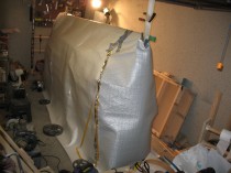
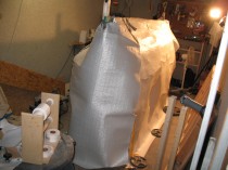
The temp on my cocooned post-curing fuselage stayed over 122°F until around 0530 am this morning.  The cooling temps overnight finally caught up & the temp began to fall, albeit slowly.  All-in-all I got almost 14 hours of 122°+ F temps plus quite a few hours more at the 115°+ F mark.  I let it continue for another few hours and then began to turn off the heaters one by one to slowly bring the fuselage down to ambient temp.  I turned off the first of 4 heaters at 0900.  I turned off another heater at 1215, turned down one of the two remaining heaters to low, and opened up the back of the post cure tent.  By 1430 all the heaters were off and I let it continue to slowly cool down.

Back to the main gear, I removed the blocks and the clamps from the gear tabs.  Layups looked good.

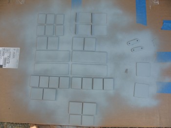
From there, I took the now thoroughly dried Alodined aluminum extrusion pieces out to the back patio.  I wasn’t overly thrilled with the quality of my Alodining process, so I decided to add another layer of corrosion control on the aluminum parts by adding a couple of coats of primer.  But, to ensure that the glass would grip to a primer base that itself was gripped firmly to the aluminum surface, all the pieces will be lightly sanded and the prepped via a wash down with Simple Green and 3M pads to remove any “loose” and/or weak primer (this is how I prepped parts when I shot paint on my chopper project… Simple Green works great and is completely clean chemically).

Aluminum Extrusions (Ch's 14, 16, 19)Aluminum Extrusions (Ch's 14, 16, 19)After the fuselage was at ambient temperature, I took apart the fuselage post-curing setup. It all came down fairly quickly.  I double checked the fuselage with my levels and it seemed to have worked.  Without the weights in the fuselage, the longerons leveled out true and equal all the way around.

Fuselage Post Cure

Fuselage Post CureFuselage Post CureFuselage Post CureFuselage Post Cure

I then spent over an hour cleaning and organizing the shop.  I have a lot of epoxy to use. So in order to actually save the money I spent on the epoxy here in Germany I’m focusing more on the actual building and not so much on cleaning the shop back to a spit-polish after every chapter.  I only have until October before I have to deploy to Tampa for 6 months, so I’m trying to get every bit of building in that I can.  This is also another reason why you’ll see me building out of Chapter sequence, to get the biggest bang for my buck epoxy-wise.  And since I have help right now with Gina being available to cut glass and mix epoxy, I’ll be focusing on the wings next and getting as much done on those as possible since they simply use the most amount of epoxy.  That being said, I’ll still have a lot of epoxy left even after the wings are glassed, but they will definitely take the biggest bite out of my epoxy stock.

After the shop was cleaned & put back to decent shape, I primed the other side of my aluminum parts.

I then reinserted the Landing Brake Actuator into the fuselage.

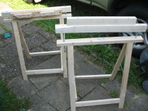
After all my odd & end jobs were completed, I started prepping for the Right Wing build.  Since the garage floor is so uneven, I decided to simply build a wood base for the wing jigs.

Chapter 19 - WingsAfter the base was complete, I located it in the center of the garage and began the process of mounting the wing jigs to it.

Chapter 19 - WingsAfter I got the first few wing jigs mounted, I took a break from the jigs and went back to work on the main landing gear.  I cut & sanded the inside gear tab layups to match the outside gear tabs.

Chapter 9 - Main Landing GearChapter 9 - Main Landing GearI then redrilled the 5/8″ holes for the final time & called it a night.

Chapter 9 - Main Landing Gear


Aluminum Stuff & Landing Gear . . .

Finally got some Alumiprep to go with my Alodine!  If I haven’t covered Alodine earlier, it is simply a corrosion protection application to keep aluminum (yes, aluminum does corrode!) from deteriorating and losing strength over time.  This is especially important for composite airplanes where these metal extrusions are embedded into the foam & glass and can no longer be assessed or examined for any corrosion–for the life of the plane–without actually tearing into the glass to see it.

The Alodine process is fairly simple:  the Alumiprep is an acid that does a super-scrub on the part to clean (etch) it.  The part is soaked in Alumiprep for a couple of minutes.  Then the part is rinsed off with water and put into the Alodine for a couple of minutes where it turns a greenish-goldish-brown & receives its corrosion protective coating.  It’s rinsed with water once again and allowed to dry.

Click here for a good video showing How to Acid Etch and Alodine Aluminum.

I also found some Rosin Core Solder for the radio antennas that will be embedded in the wings, winglets & canard.  Also had to pick up 2 more portable heaters at the base and press them into service.

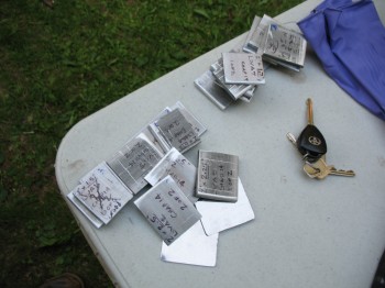
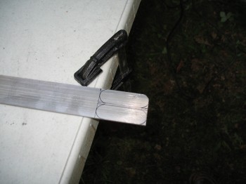
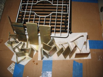
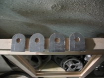
I used the Dremel & mini belt sander to make the 0.1″ & 0.2″ rounded-over edges on the aluminum extrusions.  I also cut out & made the GIB shoulder harness seatbelt tabs.

Aluminum Extrusions (Ch's 14, 16, 19)Chap 14 - Rear Seatbelt Upper Mount TabsChap 14 - Rear Top Seatbelt Mounting TabsI Alodined all the cut aluminum pieces and set them up to dry.  I had a sneaking suspicion that my Alodine was a little on the old side.  No matter what I did, pre-cleaning, leaving the piece in either solution for significantly longer, it didn’t seem to change the intensity–either light or dark–of the Alodined parts.

Alodined Aluminum Extrusions (Ch's 14, 16, 19)A little before 1600 my Post-Curing fuselage hit 122°F.  I’m going to keep it at that temp for at least a good 10-12 hours, and hopefully up to 15 hours.  Overnight may get a little problematic maintaining that 122°F since ambient temps tend to naturally fall off drastically here in Germany.

I laid up the inside glass on both the main gear tabs.  I also glassed a 3-ply BID layup on the outside of one of the tabs that seemed a bit thin (the ply-count was good, but the compression from the clamp appeared to have pushed the glass a little down towards the base of the tab, leaving the top a little thinner as compared to the other 3 tabs).

Chap 9 - Main Landing Gear Build

After a couple of hours had passed I knife trimmed the glass & cleaned up the edges… the layups looked good!


Extrusions & Fuselage Post Curing

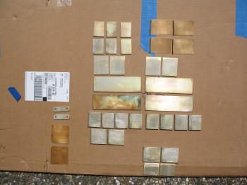
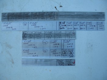
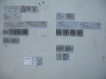
I cut all the aluminum extrusions (LWAs) for the wings & CS spar that are spelled out in Chapters 14 & 16.

LWA Alum Extrusions - Ch's 14 & 16LWA Alum Extrusions - Ch's 14 & 16I then removed the clamps from the flox gear repair & did a mock install on the fuselage… Success!

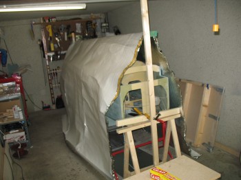
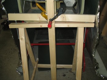
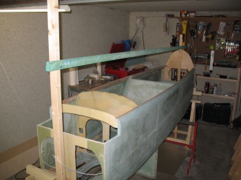
Chapter 9 - Main Gear Mock UpChapter 9 - Main Gear Mock UpI prepped the fuselage for Post Cure & spent a couple of hours locking in the fuselage so that it was level to within 0.1° across the longerons in all directions.

Fuselage Post CureFuselage Post CureFuselage Post Cure

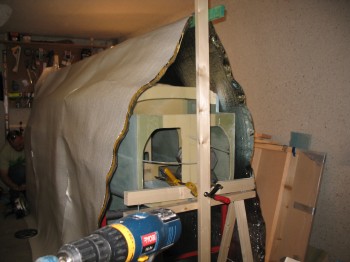
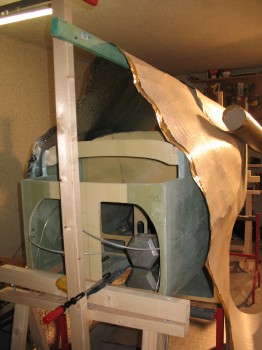
I covered the fuselage with a foil covered thermal barrier “tent” (or cocoon) and placed 3 portable heaters inside the barrier.  I started the post cure at 3:30 am and the first average temperature reading was 105-107°F.

Fuselage Post Cure

Chapter 9 – Main Gear Build (& consoles)

I knife trimmed the Right front & Left rear consoles.  I marked up the dimensions on the Right front control console, and then cut out the panel for the control stick & seatbelt access (yes, in my haste I cut the seatbelt cutout too narrow, and simply left it to cut wider later on) . . . I also removed the peel ply.

Chap 16 - Right front armrest consoleChap 16 - Right front armrest consoleI then removed the peel ply from the Left rear console & cleaned up the edges a bit more.

Chap 24 - Left rear armrest consoleChap 24 - Left rear armrest consoleI then took the Right front console out to the fuselage to mock it up & check out how it fit.

Chap 16 - Right front armrest console

After I finished for the day with the consoles, I removed the clamped wood blocks and removed the main landing gear out of its mount.

Chap 9 - Main Landing Gear BuildChap 9 - Main Landing Gear Build

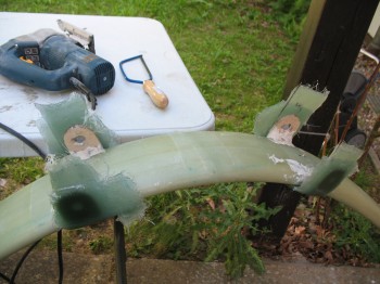
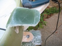
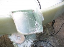
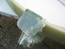
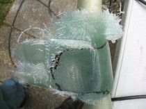
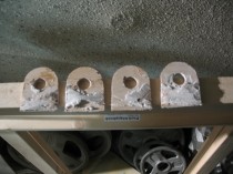
I then took the main gear outside & put in on the folding table (my portable workbench).  At first, I started to trim the excess cured glass by using a coping saw, but that didn’t last very long.  I quickly switched to something a bit more electro-mechanical, pulling out the Bosch saber saw!  It worked great (read: “fast”) and I trimmed the excess glass on the tabs down to within a respectable 0.1″ of the wood templates.

Chap 9 - Main Landing Gear BuildChap 9 - Main Landing Gear Build

Chap 9 - Main Landing Gear BuildChap 9 - Main Landing Gear Build

Chap 9 - Main Landing Gear Build

Chap 9 - Main Landing Gear BuildI Dremelled the gear-tab to gear-leg junctions to get a smooth, round, flowing edge for all the tabs.  With the Dremel I was also able to clean up & smooth out the saber saw marks around the outer edge of the tabs.

Chap 9 - Main Landing Gear BuildChap 9 - Main Landing Gear BuildI marked the center of the holes & drilled a 1/8″ pilot hole to check that I was centered in the hole (the 5/8″ hole of the wood jig).

Chap 9 - Main Landing Gear BuildChap 9 - Main Landing Gear BuildOnce I was centered, I drilled 3/8″ pilot holes & then used the 5/8″ arbor bit to drill the main landing gear holes… it worked very well!

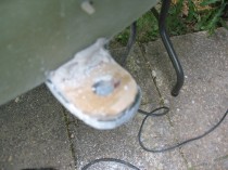
Chap 9 - Main Landing Gear BuildChap 9 - Main Landing Gear BuildChap 9 - Main Landing Gear BuildChap 9 - Main Landing Gear BuildChap 9 - Main Landing Gear BuildI tried to insert the steel LMGA tubes into the holes, but they wouldn’t go in.  I used my round Perma-Grit tools to bore out the holes a little wider, going very slowly and removing just a very little bit at a time.  It was a fair amount of work & took about an hour to do, but I definitely wanted to ensure the fit was tight and the holes weren’t bored out too wide.  Also, while boring out the holes I realized that the final fit should be without the wood jigs attached.  So I popped the wood jigs off, finished boring the holes and then spent about another hour digging, sanding, grinding, clawing and scratching out the dried (or should I say cemented!) bondo.

Chap 9 - Main Landing Gear Build

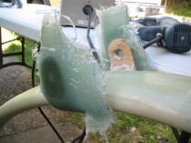
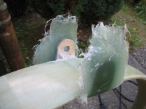
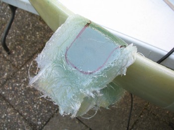
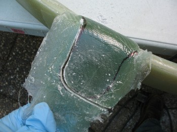
Well, I think I’ve shared my personal philosophy on building an airplane.  I’ve said over & over again that building any airplane is simply having the perseverance during the build to  repeatedly fix the things you royally screw up.  And this my friends, was one of those times.  As I was sanding the tabs, I noticed a dark line near the inside of the tab.  I sanded it down a little and messed around with it, but it was still there.  I then realized it was probably plastic from the peel ply layers.  I confirmed this by sticking in a razor blade and digging out some plastic!  That’s when I deftly thought: if it was on this side . . . ?!  Yep, there it was on the tab opposite the one I was working on.  I realized that with it being on both sides it wasn’t simply an anomaly, it was something serious & bad . . . I took the gear out to the garage and marked the edges of the tab glass and put a couple of X’s on each side for alignment purposes.  I then put some towels down on the floor, grabbed a rubber mallet and hit it a few times.  At first it didn’t seemed to do anything and all appeared solid, but I wasn’t overly convinced so I gave it a couple more good whacks and off it popped.  Smooth and shiny on the inside.

Well, I made a few phone calls & talked it through.  After a bit of discussion, I finally decided to sand each side down and flox it back on.  Besides bouncing it off some other bubbas, a few key things helped me in that decision.  First, flox is some tough stuff & it’s structural.  Second, the effort that it took me to knock the tab glass off with only a layer of plastic between the plies was significant, serving as a testament to just how much grip strength epoxy has in general–that a layer of plastic would hold so well.  And third, the configuration of the landing gear tabs has the steel LMGA tube floxed across and through each side of the tab holes, then into all of the plies on the piece that was knocked off–with the remaining plies still left on the gear–and the soon-to-be inner plies that I would glass in.  Thus, I decided I would proceed with the flox repair.

Unfortunately, the only pictures I have were after all that took place, since I was in emergency response mode and not concerned about documenting anything until afterwards.  You can see in the pics below that the flox has just been applied and the gear is back in the workbench mount with a myriad of clamps holding it tightly back into place.

Chap 9 - Main Landing Gear Build Chap 9 - Main Landing Gear BuildChap 9 - Main Landing Gear BuildI checked it out before I went to bed. . . the clamps had held it in exactly the same spot, with no slipping or movement, so I called it a night.

Chapter 9 – All Main Gear

Now that the bondo–between the wood main gear jigs and the main gear–is completely cured, I final sanded it along with the glass on the gear in between the tabs.

Chapter 9 - Main GearChapter 9 - Main Landing Gear

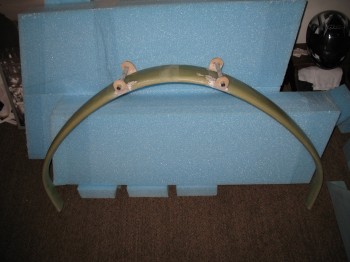
I removed the gear bolts and removed the gear bow from the fuselage.

Chapter 9 - Main Landing GearI then went on a foraging mission for materials at Praktiker & Toom (German DIY stores).

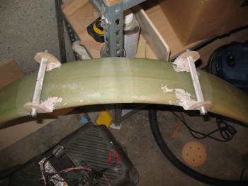
Upon returning from a successful buying venture, I marked the center of the steel gear tubes on top of the main gear & glued on two (2) small marker tabs (and marked the CL on the gear bow with a Sharpie… just in case).

Chapter 9 - Main Landing GearChapter 9 - Main Landing Gear

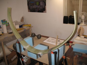
I prepped the workbench in the downstairs shop with spare wing foam pieces that I secured to the table, and then got the epoxy and glass ready (the glass that Gina had spent about 2-1/2 hours cutting…Hoo-ah! It’s awesome having help!).  I took the main gear bow down to the prepped workbench and secured it to the wing foam & table.
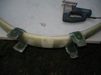
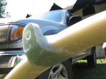
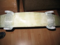
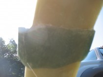
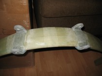
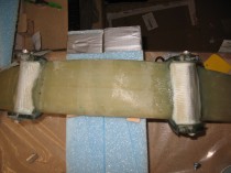
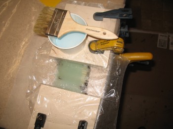
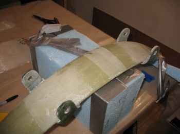
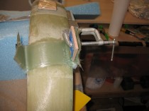
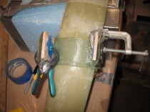
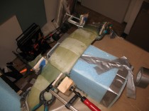
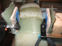
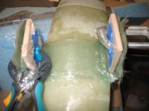
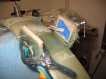
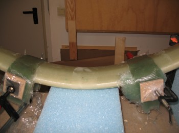
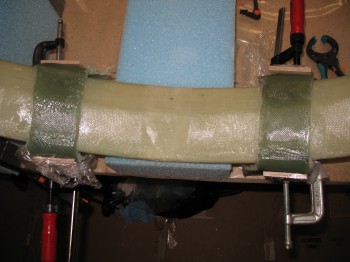
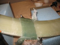
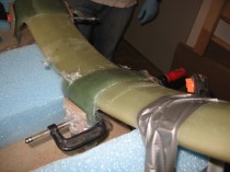
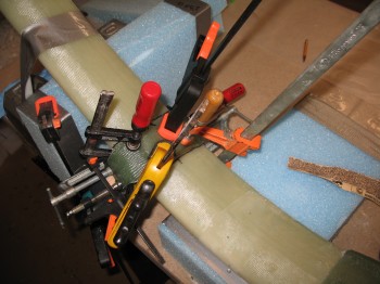
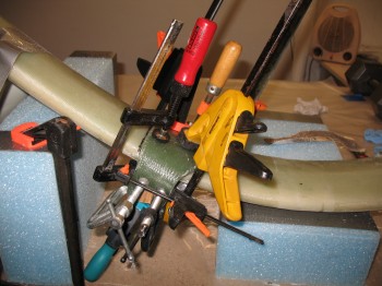
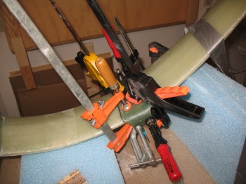
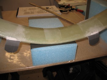
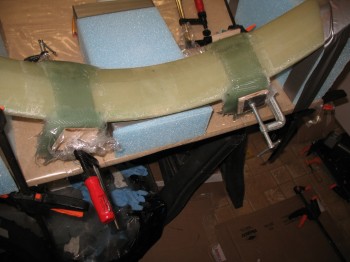
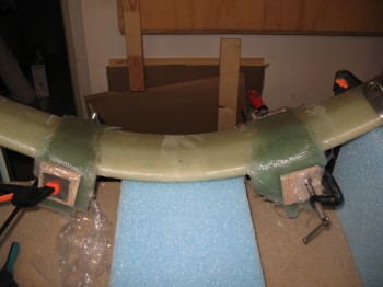
Chap 9 - Main Landing GearChap 9 - Main Landing GearChap 9 - Main Landing GearI then glassed 2-1/2″ x 12″ 18-ply UNI strips onto the bottom of the gear on each side.  These long UNI strips start & cover the tab on one side, then get laid across the gear strut and end by covering the other tab.  Analogous to a UNI “band” or “strap” across the bottom of the gear bow, for the left and right side mount.  Once the 18-plies of UNI are in place, then on each tab, placed over the now pre-existing UNI band, 18 plies of 2-1/2″ x 2-1/2″ BID squares are glassed onto each tab (only covering where the gray duct tape was applied).  So, total glass each side: 18-plies of UNI (side-to-side strap) + 18 + 18 = 36 plies BID (tabs only).  I then clamped 2-1/2″ x 2-1/2″ wood pieces covered in saran wrap (so they wouldn’t stick to the layup) over the outside plies of BID with just enough pressure to squeeze out any excess epoxy and to form a nice smooth/straight outer surface.
Chap 9 - Main Landing GearChap 9 - Main Landing GearAfter a break, I glassed the Right front and Left rear console with 1-ply of BID and peel plied.

I also went back to the gear–with the layups being a little gummy but starting to harden–and knife trimmed the gross excess of glass (it looked crazy but it’s structurally correct… promise!)


Post Curing

Now it’s time to have a serious talk about my fuselage and post curing.  First off, post curing epoxy in basic terms allows the epoxy-laiden structure to be more resistant to the effects of heat.  The key thing we focus on in post curing is the glass transition temperature or Tg.  To help explain Tg, I pulled this quote off the amt composites web site:

“When a polymer system such as an epoxy is heated, significant changes occur in mechanical, thermal and electrical properties. These properties do not necessarily recover upon cooling. A considerable change in these properties can be seen above the glass transition temperature (Tg) of the epoxy. The glass transition is the temperature where the polymer goes from a hard, glass like state to a rubber like state. The epoxy will exhibit much physical strength and stiffness below the Tg.”

So what post curing does is simply drives the Tg up to a higher point.  Post curing is done by heating up the part slowly and maintaining a high temperature for a matter of hours to days, depending on the epoxy system used.  For MGS 335, that magical temp is 122° F and for MGS 285 it’s 170° F, although MGS 285 will still benefit from a 122° F post cure. My fuselage was built mostly with MGS 285, but has a significant amount of MGS 335 in it as well.

Naturally, there’s a lot of discussion out there about the benefits—or lack thereof–of post curing, especially since post curing can, to a large degree, happen naturally just by a composite aircraft sitting in the sun and having its surfaces being repeatedly heated by the sun.  My thought (from a lot of research, not my own “expertise” here as any epoxy guru) is that it’s generally not required for the canard aircraft we build.  However, I will post cure my fuselage for two simple reasons:

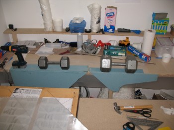
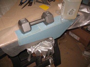
1.  My fuselage has a very slight twist to it.  As you can see from the weights that I piled up on top of it to keep it straight during the initial steps of my main gear install.  In building a Long-EZ, just about every sacred measurement, from wing incident to the strakes, relies on reference to the longerons.  They should be as straight as possible.  So, I hope to set the fuselage straight and then post cure it to lock it in to position as best possible.

2.  Again, since I’m building in Germany right now, I want to ensure that the fuselage maintains its shape as best possible once I get it as close to straight as possible.  Once it goes in the shipping crate I have no idea what actual route it will take from Europe back to the States.   I envision it sitting in a hot shipping container baking on the docks in Savannah, GA or some other decently warm locale.  The higher the Tg is, I figure the more resistant it will be to any structural changes.  Overkill?  Maybe.  But I figure the fuselage is the epi-center of a Long-EZ build, so I’ll try my best to get it, and keep it, as straight as possible.

Consoles, Post-Cure & Gear

I started the day off focusing on the fuselage consoles.  I cleaned up the BID tapes I glassed last night on the consoles/armrests & removed the nails holding the console tops to the sides.

I notched the top of the left rear console (below) to prep it for an eventual install of a rear throttle quadrant.  Unfortunately, when I mocked it up I completely failed to take into account the ergonomics of where the throttle quadrant SHOULD BE positioned.  The positioning at the front of the arm rest is WAY too close to the GIB and needs to be much closer to the front seat.  No worries!  This is composites and I’ll simply fill that void in later!

Chap 24 - Left Rear Console/ArmrestI then took the consoles out to the garage and mocked them up in the fuselage.  Again, since the fuselage side is curved and the console side edges are straight, I was just looking for the general look, fit & position of the consoles.  That being said, I did take some time to shape the outer edge of the front right console & carve the depression near where the control stick area mates to the side wall/control stick depression.  I then rounded over all the corner edges with a 3/8″ router bit.

Chap 16/24 - L & R rear consolesChap 16 - Left Front ConsoleI cleaned up any left over/excess micro and errant strands of glass on the 3 consoles. I’m waiting to build the front Left console until I nail down the mounting configuration for my throttle quadrant.  The final tally on the consoles today is that the Right front & Left rear consoles are ready for exterior glass.

Now, the plans call for simply glassing 2 plies of BID over the entire exterior of the console and overlapping the layup onto the sidewall, fuselage floor, seats, etc. to secure it into place.  Since I won’t install these before they get shipped back to the States, I want to provide the foam with a little protection.  Thus, I’ll be glassing one ply of BID onto the exterior of the consoles, and then using a 2″ BID tape AND one more entire layer of BID to attach the consoles to the fuselage when I glass them in later on.  It will add just a bit more weight, but then I don’t have to worry about my foam getting all dinked up in the upcoming move back stateside.

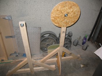
After I finished with the consoles for the day, I focused on the post cure prep for the fuselage.  I’ve spelled out the details and reasonings for the post cure in a separate post today.  My first task for the post cure effort was to make 2 stands that were capable of being adjusted on each corner in order to ensure that the fuselage is straight and remove any twist it may have.  I cut threaded rods into 4 pieces measuring 9.75″ each.  I used some 2x4s with holes drilled through each side and created a screwjack for each side of the 2×4, that will sit at the outside corners of the fuselage (sorry, no pics yet).
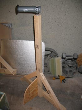
While I was at the DIY store I picked up a piece of PVC pipe to serve as my 3″ UNI tape roll dispenser for when I lay up the spar caps on the wings, CS spar and canard.  I retired the spit posts and pressed one of them into service as the new 3″ UNI tape dispenser.
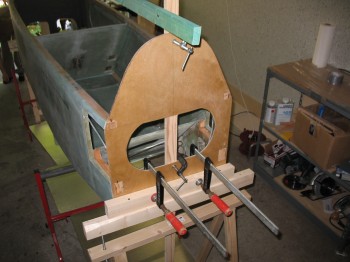
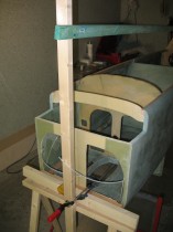
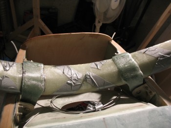
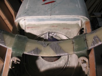
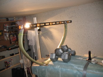
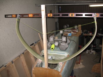
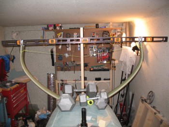
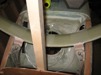
Retiring the spit posts!Chap 19 - 3" UNI Tape Roll "Dispenser"I then turned my focus back to the main gear.  I situated the fuselage back inverted and placed it on red stands.  I leveled the fuselage longitudinally & laterally using weights to hold it in place.  I then ensured the firewall was leveled vertically & clamped a 2×4 to it.  (I had previously marked the 5/8″ OD steel gear mounting tubes (LMGAT) 0.65″ from each edge, put wood jig tabs in place, and remounted them onto the fuselage-side main gear extrusions).  I put the gear in place and used an adjustable string setup to keep it upright and at the right distance from the firewall.  I taped a 6′ long carpenters level to the bottom of the each gear leg, centered front-to-back so as to minimize any error.  I set the gear with a 3/16″ gap between the top of the gear arch and the bottom of the fuselage longerons.

Chap 9 - Main Gear BuildI then set the axles’ centerline at F.S. 111.1 (stock plans is F.S. 110.5, but because I’ll be mounting a heavier IO-320 engine and some discrepancies I see in the plans, I’ll be moving the axle positions back about 1/2″ . . . [Ed. See my buddy Marco’s in-depth discussion on this at longezproject.blogspot.com… he explains it all nicely])

Chap 9 - Main Gear BuildAfter spending an hour or so ensuring that everything was lined up, straight, square… and that the measurements were as spot-on as possible, I bondo’d the wood jigs (that were pre-installed on the fuselage) to the main gear bow.

Chap 9 - Main Gear BuildChap 9 - Main Gear BuildAfter the bondo cured for a bit, I trimmed the excess off & cleaned it up, and then left it alone to dry overnight.

Done with Fuselage… for now

Today I knife cut the aft bottom fuselage layup at the front edge of the hell hole.  I removed the peel ply, sanded and cleaned it up a bit.

I put 1-ply of bid on the rear seat back and the rear seat pan (fuselage bottom) junction, and patched the errant hole mishap.

I turned my attention to the fuselage interior consoles (arm rests) and went to work on them in the downstairs shop.  On the Right front and the Left & Right rear seat consoles, I mounted the top to the sides with finish nails through the foam.  I then pre-pregged about a 1-1/2″ of strip of 1-ply BID and laid it up in the corner along the seam between the tops and the sides of the 3 respective consoles.  These will get more glass later when they get installed into the fuselage, so about a 3/4″-1″ overlap on each part will hold it fine.

I used straight fast hardener & let the consoles set for around 15 min, then I turned them right side up and set them on the side of the work bench, held in place with weights so that they would cure at the proper right 90°angle between top and sides.

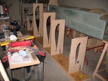
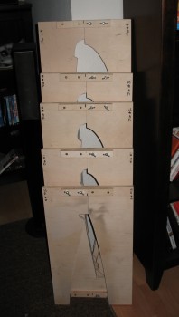
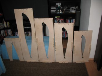
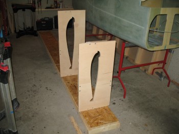
Chap 16 & 24 - Front R console & Rear L consoleChap 16 - Rigth Rear console/arm restWhile the consoles cured, I took the remaining Trailing Edge Wing Jig pieces to the wood shop on Ramstein AB.  I cut jigs #1-4 on the band, jig & table saws to produce their desired shapes.  I then took the jigs home & finished them by drilling the holes, sanding and installing bolts, etc.

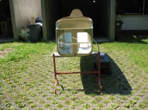
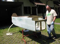
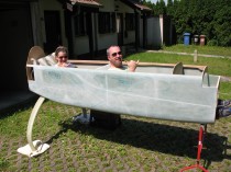
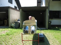
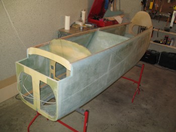
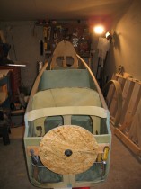
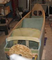
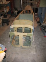
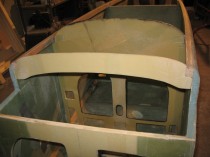
Chap 19 - Wing jigs completedChapter 19 - Wing jigs ... completed!I then wiped down fuselage to remove all the fiberglass dust, took it off the spit and began taking a myriad of pictures.

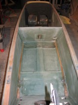
Completed fuselage"The Picture"The Help! :)