Chapter 14/23 – Baffling Extrusions

Within a day of coming back from NC I started feeling a bit sluggish, and felt a cold coming on.  Well, today it hit me pretty hard, so I’ve been moving at a bit slower pace.  I’m hoping tomorrow I’ll feel well enough to get the lower engine mount extrusions glassed into place.  On top of all that, when I woke up this morning it was a virtual winter wonderland outside, with snow continuing to fall and a good few inches already on the ground.

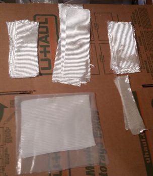
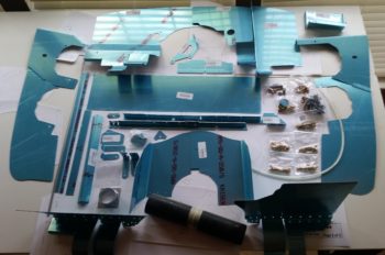
So I grabbed a cuppa and went through Mike Beasley’s baffles and –while looking at his website– taped a number of the pieces together to get a good idea what his were all about.

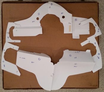
The initial confusing part on his just looking at them is that all the annotated & marked sides are actually the interior side of the baffles, with the blank sides ending up what you see when you piece them together, or the exterior side.

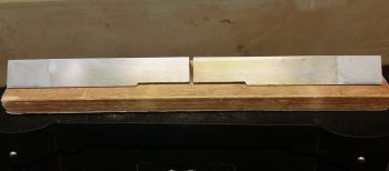
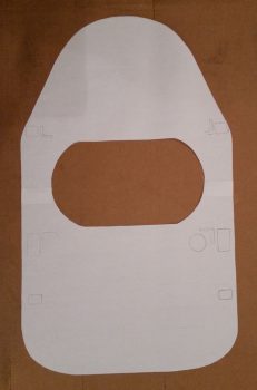
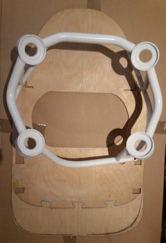
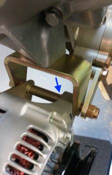
So once I got that little tidbit down, I was able to get a good handle on what was going on.  Here’s the inside (looking aft) of the lower skirt that wraps around the alternator & starter.

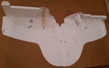
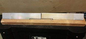
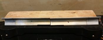
Here’s the top looking aft.

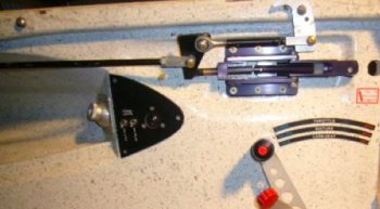
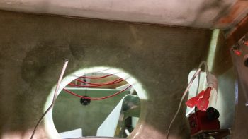
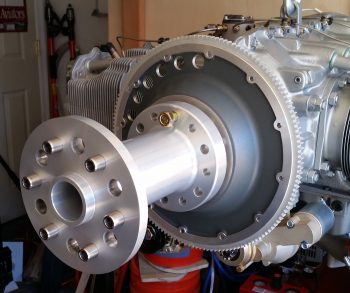
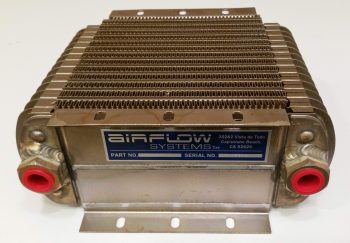
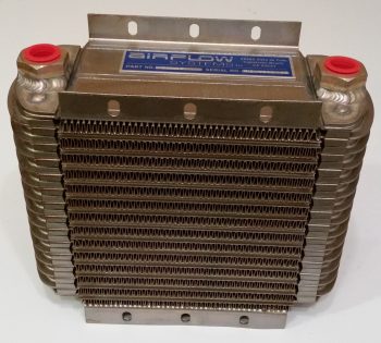
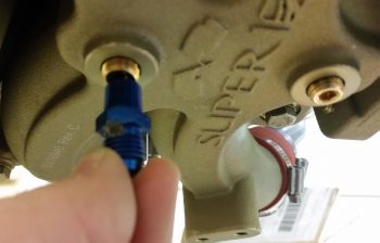
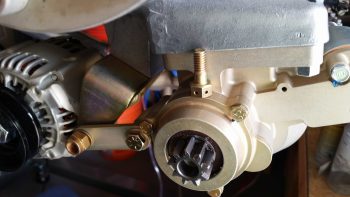
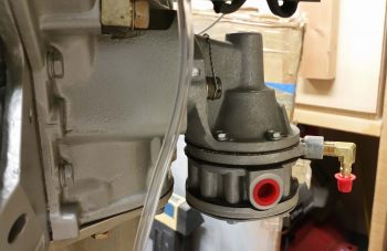
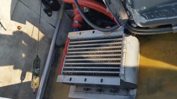
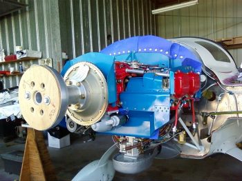
Now, since I’ll have my oil cooler in the plans location on the side of the engine and not nestled in the aft underside region of the motor, I won’t need the aft lower skirt positioned like Mike’s (and countless other EZs) so far aft that it just barely covers the aft end of the alternator and starter.  Here’s Marco’s oil cooler in the plan’s location, just forward and to the left of the motor.

Here’s Mike Beasley’s real world baffles, with the lower baffle skirt far aft to account for the oil cooler placement.  If I were going to place my oil cooler in this location, I think it might have been a better, cheaper option to just use Mike’s Beasley Baffles.  From what I can tell Mike really did a bang-up job on his baffle templates, so they are certainly a viable option for most builders that are installing an O-320.

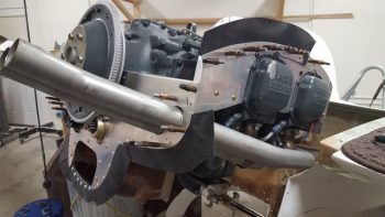
That being said, here’s a lower baffle skirt placed much farther forward that has both the alternator and starter exposed, but still has a centerline mounted oil cooler.  My baffles will look more like this, only without the oil cooler mounted in the centerline position.  So in my situation I think it will work out better having the VANs baffle kit on hand to modify.
(To be clear, I will be using Mike’s baffle temples extensively –as I have been doing– to modify the VANs baffle kit).

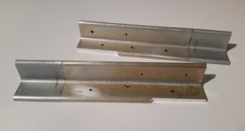
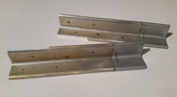
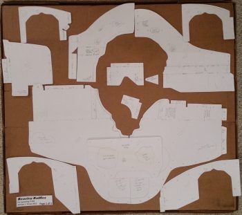
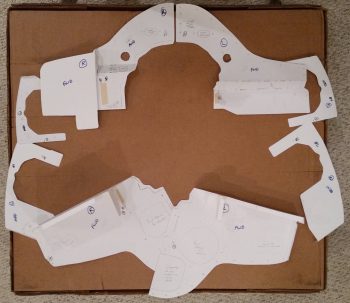
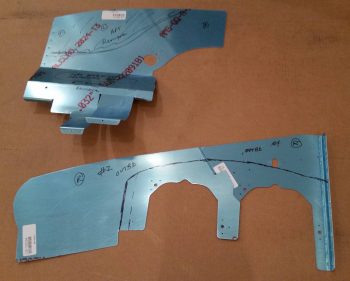
I then compared Mike’s baffles to the VANs, and assessed what I would need to modify on the VAN’s baffles.  On the set of side baffles (bottom of pic) you can see my proposed line cuts off that big blank piece of aluminum, which would be on the aft side.

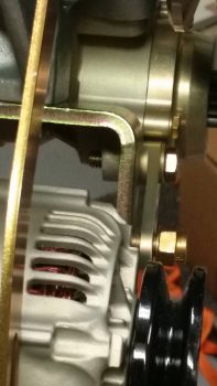
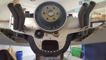
This expanse of baffling would normally match up to the considerably wide shelf going aft of the cylinders (see 3rd pic from top, above) and which then drops down to create the skirt running across the aft faces of the alternator and starter.  Here’s another example on Mike Beasley’s bird.

Again, since my lower aft baffle skirt will be located forward of the alternator and starter, I only need a very narrow shelf just aft of the rear cylinders to then drop down to create the lower baffle skirt.  Here’s a good depiction of what I’m talking about on Buly Aliev’s Cozy, where he used the VANs baffle kit.

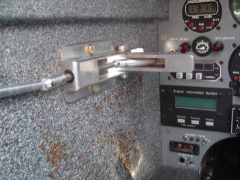
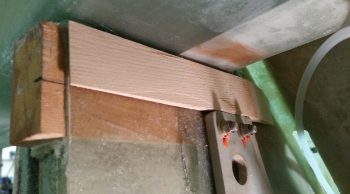
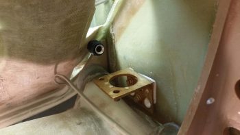
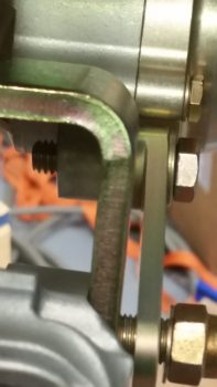
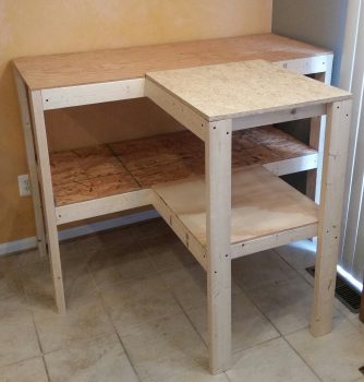
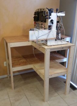
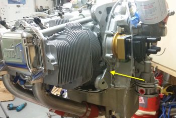
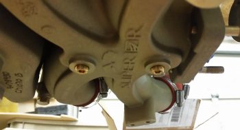
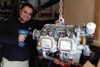
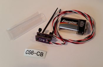
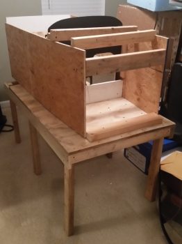
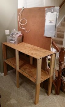
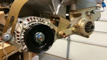
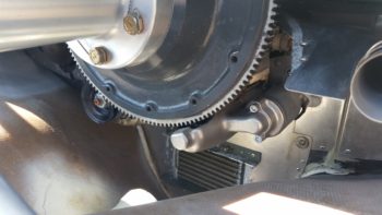
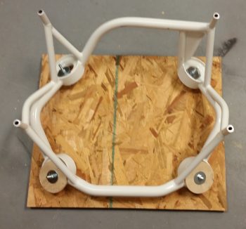
I then made it down to the shop to get a little bit of prep work in for installing the lower engine mount extrusions.  I copied Dave Berenholtz in bolting a wood plate to the engine mount to help easily ascertain the mounting angle of engine mount/engine during the installation of the lower extrusions.

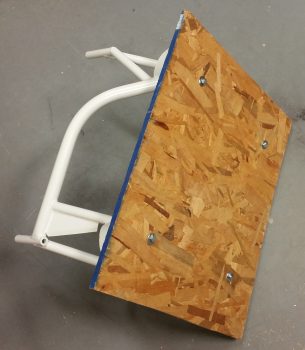
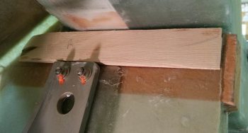
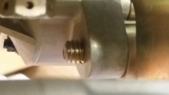
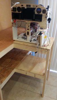
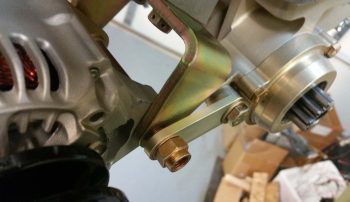
Here’s another shot.  BTW, the plans would have you install the engine mount so that the prop is 2° higher than the front (firewall side) of the engine.  This makes sense since the Long-EZ, like many aircraft, flies about 2° nose high.  However, remember that the 2° number is based on a 118-125 HP Lycoming O-235 engine.  If you’re pushing a few more ponies, which I and most people are these days in Long-EZs, then it takes less angle to keep the nose up.  Also, 2° high on a higher powered engine probably won’t get you level flight, but a slight climb… which then of course would mandate more trim forces in play.

For example, with a planned 220 HP engine, my buddy Dave B. set his angle at 1.1°.  So for my 180-190 HP motor, I’ll be setting my engine angle around 1.4°.

In addition to fiddling about with the baffles, I also tweaked the lower engine mount extrusions install plan and will hopefully get these guys glassed in tomorrow, or the next day (depending on how I feel of course).


Chapter 14 – Lower engine extrusions

This morning, as it was raining and sleeting outside, I decided to let the shop warm up a minuscule amount before heading down.  So I started off my day by creating yet another tab on my Excel build tracking spreadsheet to compile all the pertinent engine torque values.  This endeavor involved calling a couple of companies, one being B&C, to obtain/verify torque values on their products.  In addition, some of the engine torque values were shared with me by master engine & Long-EZ builder, Chris Seats.

In other news, over the past couple of weeks I have decided to undertake yet another mod (I know, I know . . .!) and build a new canopy latch based on Mike Bowden’s design since his high horizontally-situated/activated latch works much better for my configuration (read: operating space) than does the rotary latch extending down in front of the left-side panel.

Although based primarily on Mike Bowden’s design, I will combine it with the forward latch catch manipulating features of the mystery Long-EZ that I somehow have a pic of, but have not been able to find who owns it or built it.  Coincidentally, as I was compiling a buy list of all the materials I would need to construct this latch, I got a text from Mike Bowden… who graciously provided me a plethora of dimensions that I had asked him for regarding his canopy latch.

It being a very cold day outside, I also decided to do some more assessments on oil heat fittings and firewall pass-thrus before adding them to the buy list as well.

I then finalized updating/verifying the numbers on my lower engine mount extrusions install diagrams that I whipped up in PowerPoint a couple of years ago.  I also did an inventory on the glass I had cut out about a year and a half ago (IIRC). Although it was prepped for being merely wet out in prepreg and then cut, I decided to cut it into its separate component pieces.  I then had to carefully move the engine-on-hoist out of the way so I could then drop down the glass cutting table to then cut some more BID to finalize the glass prep for glassing-in/mounting the lower engine mount extrusions.

Since my fuselage is just a hair wider at the bottom (talking around 0.1″) I decided to forego the “standard” bottom engine mounts of 1/8″ thick by 1.5″ x 1.5″ 2024 angle for ones that are slightly more robust (i.e., take up the gap with aluminum vs glass) at 3/16″ thick with 1-1/4″ x 1-1/4″ legs.

Any longer legs on the engine mount extrusions other than the 1″ stock seem to need some trimming to lessen the height right at where it meets the main gear extrusion. This is so when the thick pad of BID that the extrusion gets mounted atop of (technically below on the bottom extrusions) there is some wiggle room for the engine mount extrusion to get pushed further from the CS spar and more towards the main gear mount extrusion, while avoiding any unwanted collisions betwixt the two.

Thus, for the area of the vertical leg on each lower engine mount extrusion, I removed about 0.2″ at the lower edge.  Again, just for the area immediately above the main gear mount extrusion.  I started by marking the engine mount extrusions.

Then clamping each one to my work bench –with the help of 2×4 underneath the angled aluminum to stabilize it– and used my trusty Skil saw to trim it down.  Worked a treat!

I then cleaned up each thinned out area with a hand file.

After sanding the outboard and top sides of the extrusions that will mate up to the BID pads and flox with 220 grit (as per plans), I then washed the extrusions down in warm water and Simple Green.  I then took them upstairs to mark up the bolt hole locations in accordance with the plan’s dimensions.

To ensure I don’t lose my bolt hole locations with Sharpie-destroying/blurring epoxy (after I double-checked all the measurements!) I took my drill with a small bit and drilled the slightest of a hole beginning at each mark.

It was getting late, but still wanting to get as much done during this very cold spell of weather we’re having, and to free up as much time as possible during the upcoming good build weather (if it ever comes! ha!), I decided to cut out my Beasley Baffles templates that were created by the benevolent Mike Beasley.

If you remembered that I purchased a 320 engine baffle kit from VANs Aircraft, you’d be correct.  So you may be asking why I need to cut out the templates from the ones Mike B. so graciously (yes, a lot of gracious canardians around . . .) provided me.  Well, the VANs baffles would be a great direct use-as-advertised item if I was building a tractor, top-down cooling airplane with an RV style cowling.  But clearly I’m not.  So although the VANs kit will give me a huge head start on the engine baffles, it will not be without a good amount of modification to get it all to fit and work.

That’s where Mike’s Beasley Baffles come into play.  Since his baffles are specifically for a 320 in a Long-EZ, it allows me to dial in my baffle design much, much closer by using these templates to modify the VANs baffle kit as needed.

As a reminder, Mike sent me his Beasley Baffles via email in electronic form a bit before RR last year.  I then took the 3 files down to Staples and hand them printed out on card stock. As for tonight however, it took a good hour and a half to cut these baffle templates out of the card stock.

When I went upstairs to grab the Beasley Baffles to cut them out of the card stock, I also grabbed the outline of the firewall I had traced onto 2 large pieces of scrap paper I had.  I cut & taped the firewall outline together for a real size version of my firewall that will help in determining the final layout and configuration of all the firewall components.

It’s supposed to snow tomorrow, so I’ll assess next steps in regards to installing the lower engine mount extrusions either tomorrow or the day after.  In the meantime, I’ll continue to work any tasks of opportunity that are good for rainy day tasks that I don’t want hanging over my head when the good build weather finally arrives.


Chapter 14/22/23 – Engine mount prep

I started off today by getting a bunch of paperwork in order: updated chapter to-do task lists and some powerpoint slide decks I keep on different big upcoming tasks like the strakes.  This took a few hours, after which I headed down to the shop.

I was very pleased that with an ambient humidity reading of 36% in the shop . . .

that my new engine dehydrator configuration yielded only 18% humidity internal to the engine!  Now, that’s more like it!  Anything under 30% is good and means minimal moisture in the engine, so obviously 18% is way better . . . that helps, but I still want to get this engine pickled soon.

Part of the process (or at least my process) in prepping for installing the lower engine mount extrusions is to figure out where all the hell hole resident items go.  I have a mount for the oil heat pump, and the laser altimeter for the nose gear’s new AEX system will reside on the bottom of the aircraft in the hell hole area, so the component most needing a home was the B&C SD-8 B/U Alternator relay.

My initial thought was to have it on the aft side of the GIB seat back, where I’d use a click bond stud on one side and a RivNut on the other.  However, to do either I needed to open up the slots on each end of the relay to accept a #10 screw.

I used a 3/16″ drill bit first, then subsequently a 13/64″ drill bit, to open up & widen the slots on each end of the relay.

After poking, prodding, and probing around in the hell hole, I realized with all that was traversing through this busy area, and really wanting to keep components that can more easily get snagged away from the opening in the GIB seat (for cramming stuff into for much-needed storage during flights), I decided to place the SD-8 relay in pretty much the same spot that had once been ID’d for both the electric fuel pump and the GRT MAP sensor (both which have moved on to greener pastures): the bottom side of the CS spar.

I then taped up the bottom of the relay to protect it against any untoward glue-goobers, roughed up the face of each click bond (I can’t use a RivNut on the lower CS spar cap), then cleaned the click bond mating surfaces with Acetone…. making these babies ready for some 5 min glue!

Woah!  As I was holding up the relay for a final location fit, I could visualize chunks of skin getting extracted from my forearm (accompanied by a stream of appropriate expletives) from the protruding click bond posts while I glassed in the lower engine mount extrusions. Since these click bonds can quite easily be glued/glassed in at a later time, I decided to table this exercise for a date AFTER the lower engine mount extrusions were installed.

For about 6 years now, ever since I skinned the outside of the fuselage, I have dealt with the pair of coiled-up 1/8″ aluminum brake lines in the hell hole.  Well, I hit another major milestone today in that I finally –after all these years– trimmed those suckers down to a manageable length.  In the not too distant future I will complete the brake line runs from the wheel all the way to the master cylinders.

I then scrounged up the lower WA16 wedge shaped pieces of Spruce that make up the base for the lower engine mount extrusion glass.  Just as on the top, these WA16 Spruce wedges serve to align the engine mount posts more parallel to aircraft centerline and less with the curved sides of the fuselage.

I had to trim the upper front corners of each one to get them to slide forward enough, but after a couple of trial and error rounds I got each side to fit in nicely.  Since I will not be flipping the fuselage upside down to install these lower engine mount extrusions, I’m kicking around the idea of floxing these WA16s in place first with some peel ply over top to minimize the variables when I glass in the engine mount extrusion BID pads.  We’ll see . . . more assessment & eval required.

Again, in prep for the upcoming lower engine mount extrusions installation, I had to temporarily evict another hell hole resident: the FT60 Red Cube fuel flow transducer.  If it was just the Red Cube I may have considered just taping it up, but with it’s pesky wire pigtail and the fact that it needs a good wipe down before final install, I yanked it.

I’ll of course cover up the remaining fuel line and FT60 mounting bracket with protective tape during the lower engine mount extrusions install.

I then called it a night for shop work and did a bit more research on installing & safety-wiring my Fumoto engine oil quick drain valve.  I also did a quick inventory on some more engine fittings and hardware for my upcoming monthly (apparently) ACS order.

With crazy snow forecasted for the next couple of days, I’ll continue to prep as much as possible for the lower engine mount extrusion install.  Just as a point of note: these extrusion installs, followed by the engine mount itself getting installed and subsequently attached to the engine –to facility mounting the engine to the engine stand– is priority #1 at this point of the build.


Chapter 23 – Engine Preservation

Today I took a hard look at my engine preservation steps.  I’m not exactly sure what’s going on with my engine dehydrator.  It’s definitely doing something because the “dilithium” crystals (desiccant) are turning pink, but the humidity sensor on my out air line keeps showing an internal relative humidity only about 5% less than ambient in the shop.  An example for clarity, say the shop RH is 37%, than the air out of engine will be around 32-34%.  Maybe the 40 gal fish tank air pump I’m using is not big enough and I need more air getting pushed through?  Or the fact that this engine has gaping holes (albeit taped up) in it since it’s not all put together?  Not sure.

I did rewicker the dry air to enter the engine via the oil filler neck and out the crankcase vent vs. the other way around.  Also, I disconnected the out line that was going back into the air pump and instead of a closed system I’m trying a simple dry air in and then wetter air out to shop air.  I’ll assess if this has any impact on reducing the internal moisture in the engine.

I then tried my hand at baking all the pink desiccant I had collected in a small plastic tub.  I put it all on aluminum foil on a baking pan, fired up the oven to 240° F and cooked them for about 1.5 hours.

As you can see (although I guess a before pic would have been a good idea eh?) this baking thing really works and turns the quite pink desiccant crystals back to blue.  It’s hard to capture the brilliant blue with a camera, but it’s a drastic difference.  Pretty cool.

Although I have no doubt that my desiccant efforts is vastly helping keeping my engine internals dry-er, it doesn’t negate the fact that I need to get this engine pickled… and soon!  Thus, weather be damned I’m going back into the shop! (currently in the 30’s and it’s supposed to snow 2 days this week….Ugh! )

I had 2 major issues regarding engine preservation that until this afternoon were unresolvable:  1) I need to be able to cycle through each cylinder to TDC and BDC for spraying preservation oil into the cylinders.  Clearly I can’t do this with the engine dangling by a chain on a hoist. 2) I need to be able to rotate the entire engine upside down to bath the cam in oil/preservation juice.  To solve both these issues –and be able to have the engine on-hand but stored in a smaller form factor– I bought an engine stand from Harbor Freight that will allow me to mount the engine to the stand so that I can handle the 2 issues that I mention above.

This means next steps are to finish (ASAP!) the glassing in the lower engine mount extrusions, get the engine mount bolted in place and then use the engine mount to mount the engine to the stand.  This will allow me to then do all the steps I need to for proper engine storage.  Also, it will allow me to get the engine out of the shop and into my pool hall/rec room/storage so it’s in an a climate controlled area with much less shop dust floating around.

I’ll then finish off mounting the firewall in prep for the canopy build.

I started this phase of the build by going down to a coffee joint and reviewing all my engine extrusion mounting tasks.  I then took a look at some fellow builders’ sites who have finished installing their engine mount extrusions (Dave Berenholtz, Mike Beasley, and Ary Glantz).  I then reviewed the actual build plans.

In real world time, I’ll probably start off with mounting a couple of hell hole items, then finalize my plan and start glassing in the lower extrusions NLT Thursday.


Chapter 3/22/23 – Work bench finished

I started off today by going down to my local Village Hardware store to see if they had a #8 “aircraft grade” 1-1/4″ x 5/16-18 bolt on hand.  This little hardware store rarely disappoints and they continued their tradition today.  The 1″ bolt I had in place for mounting the alternator-to-starter support link was just a tad short and I wanted to keep with showing the requisite 2 threads on any given mounted bolt.  As you can see, the 1-1/4″ bolt does the trick.

[If you’re wondering why I went with a #8 grade bolt here, try finding course threaded 5/16″ bolts on Aircraft Spruce, Wicks, etc. If you do, they are most likely very expensive and for a very specific purpose, such as my Lycoming starter mounting bolt].

As visible in the pics above, I already have one washer in place, and with either an added lock washer or a set of Nord-Locks there will still be visible threads.

Yes, not overly exciting stuff to report on a workbench, but in the reality of my upcoming move to NC it is a necessity of sorts that demanded a bit of time to complete this workbench for electrical work, storage, and of course a place to work on my instrument panel mockup.

I finally got my instrument panel mockup off the floor and back onto something where I can both clearly see what I’m doing (without killing my back!) and have unobstructed access to 3 sides of the panel mockup.

Another shot of the instrument panel mockup’s new home.

Although a minor detail, whenever I ventured to the aft side of the panel mockup to do work I often found myself inadvertently kicking or stepping on the battery charger that was lying on the floor.  Well, no more!  With a nice industrial wood bench I simply mounted the battery charger to the work bench frame.  A minor feat, but definitely a nice improvement over what I had before.

I then took a break after my bench building endeavors and set about to adding a number of additional component serial numbers to my Excel spreadsheet tracking list.

Moving on . . .

As I was returning home from NC I stopped off to check my mail and noticed my driver’s side headlight was out.  I had bought my other headlight at Advanced Auto Parts, and coincidentally, this auto parts chain just bought out CarQuest, the maker of the belts that B&C sells for their alternators.  Armed with that knowledge, when I went to buy a new headlight I queried the folks at Advance Auto Parts about ordering a couple new shorter alternator belts (again, since I now have a 7.5″ diameter flywheel pulley).  For some reason their system wouldn’t let me backorder the belts, so when I got home I tried online. No joy.

After spending another half hour looking for these darn alternator belts, I punted and decided to simply order them from B&C.  In an effort to consolidate, be efficient and have no wasted motion on my B&C order, I decided to finalize my requirements for the engine grounding strap and order it concurrently with the shorter alternator belts (primary + spare) . . .  but how long did the grounding strap need to be?  And what size mounting bolt holes on each end?

I spent a few hours researching the best location for the engine ground. Yes, there is a nice factory provided threaded hole on the left side of the engine casing, but since my firewall ground post and starter are on the right side, I am attempting to keep the engine ground strap on the right half engine crankcase if possible.  Finding a spot to mount the engine ground strap also required spending well over an hour digging into my baffling requirements, since I am attempting as best possible to stay clear of any baffle mounting holes.  Again, since both the starter and the firewall grounding lug is on the right side, I also wanted my engine grounding point location to be on the right side engine case for the cleanest electrical path.

After assessing what other builders had done, getting a decent layout of how the baffles would get mounted, and having a general targeted area of where I wanted to mount the engine grounding strap, I then mocked up my engine mount onto the firewall (lying horizontally) to get a decent swag as to the required length of the engine ground strap.

My original goal for the engine ground strap was to get it as close as possible to the starter, but besides mandating a much longer ground strap (weight), the best mounting positions for a ground strap are holes that will be used for attaching the baffles to the engine.  I decided that if I have a good location on the forward right engine case (next to the accessory case but still right engine half) that the electrons will still easily be able to make their way through about 16″ of good steel.  If not, I’ll readdress as required.

After scouring the right side of the engine for a good spot to mount the grounding strap, I finally decided on the location (yellow arrow above).  I then extrapolated the required grounding strap length and double checked it with my engine mount on firewall mockup. The resulting strap length, with some room for maneuvering through the maze of hoses, etc. and generally slack for anti-vibration purposes came out to 13″, with a 5/16″ mounting hole on each end.

Thus, my final act of the evening was doing what I do best on this build: spend money! I pulled the trigger on two 7312 XL alternator belts (again, primary and spare) and 13″ engine grounding strap.

Currently, that completes the inventory for all the required major engine components, minus the fire sleeved hoses.  I’m sure a few bits of hardware and fittings etc. will be required, but I’ve closed out all engine component requirements that I am currently aware of.


Chapter 22/23 – Engine Parts? Check!

I understand that buying stuff for the airplane is not necessarily building.  However, at the risk of sounding like a broken record, the research & collaboration that goes into deciding what to buy is often lengthy, in-depth and time-consuming. I realize that I’ve been identifying and detailing a lot of the pieces/parts that I’ve bought over the last month or so, but a lot of that is due to the current cold weather and my downtime during household good move trips/visits to North Carolina.  Again, the fact that there’s so much research that goes into the decision of what to buy is a big reason why I post the items on this blog, because it is actually a big deal (IMO) to first make the decision, then get the item in hand.

With my blogging methodology now fully explained <wink>, I’ll get into the stuff I could do (e.g. aforementioned research & acquisition) during my trip down to NC.

Over the last week I’ve researched flywheels to enable me to pick the best one for my configuration.  To back up just a bit on this story, my initial flywheel conversation during my engine build with Wayne Blackler, Sky Dynamics, Power Sport and ECi (Continental) convinced me to NOT go with Sky Dynamics’ lightweight flywheel, which was my initial flywheel selection.

Over the past few days I spoke with B&C about 7.5″ vs. 9.75″ alternator pulley wheel diameters with them stating that there’s a negligible difference at low RPMs and no difference at normal operating RPMs.  I then again spoke with Sky Dynamics and then Sam from Saber Manufacturing (super informative) regarding my flywheel selection.  I did a bit more research then was ready to pull the trigger.  I talked to a couple of aircraft parts places, and narrowed down my selection to 2 possible flywheels: one in Nevada and one in Florida.  Air-Tec, Inc. in Florida won out since they had a new -360 flywheel (I have to use a 360 flywheel due to my 1/2″ prop flange bolts) with a 7.5″ diameter alternator pulley wheel and 149-tooth starter ring, so I pulled the trigger.

It arrived today and it really is a beautiful hunk of metal.

I chose to use the 7.5″ diameter pulley wheel since it reduces the flywheel weight by about a pound.  A standard 320/360 flywheel with a 9.75″ pulley wheel weighs 6.3 to 6.8 lbs, and my flywheel weighs in at 5.72 lbs.  To be clear, my flywheel is NOT the lightweight flywheel that Sky Dynamics sells, which has a total weight of 4.1 lbs.  For me, the bottom line is that I am really happy with this flywheel!

I wanted to ensure all the parts actually fit, so I test fitted the flywheel on the engine prop flange, then checked the fit of the 8″ prop extension.  Admittedly, I called Sam at Saber Manufacturing a couple times today just to ensure I wasn’t mucking anything up, specifically since the prop extension is machined to have as just about as tight as fit as possible on the center 1/2″ cylindrical extrusion of the prop flange.

With the engine hanging off a chain and thus not stationary, I couldn’t really manipulate the prop extension to get it to seat fully on the flywheel.  Moreover, I need to install a shorter alternator belt than the one I received with the alternator (knowing that 9-3/4″ dia. pulley flywheels are way more prevalent than the 7.5″ pulley flywheels, I denoted that on my original alternator order… always something to backtrack on!) so I definitely don’t need to experience the pain of working on the incredibly tight-fitting prop extension twice if I can just do it once.

The bottom line here is that I now know that all my major engine parts play well together and that the only outstanding engine part I currently need is a shorter alternator belt!

Speaking of engine components, I also received the Airflow Systems 2006X 13-row oil cooler that replaces the much too big 17-row 2008X model.  I had expected that might be the case even when I ordered the 2008X, thus why I never opened the box.  But again, having finalized my decision on the oil cooler model size, I quickly opened this sucker up to check it out.

Except for one minor bend on one of the mounting flanges, it looks like a really nice unit. Moreover, I think it’s a great compromise between performance and weight/size.

Continuing on with my components acquisition review, I also received 2 more stainless steel firewall pass-thrus.  These are the same size (1/2″ ID) as the one I picked up for running the CHT & EGT wires through the firewall from the GRT EIS4000.  I’ll test & eval this pair of firewall pass-thrus to use for traversing the throttle and mixture cables through the firewall, without having them attached to the firewall.  In addition, just as with the previous one I picked up for the CHT/EGT wires, at least 2/3rds of the threaded part will be removed to reduce the weight significantly.

In a discussion I had with my engine builder, Tom Schweitz, towards the tail end of the engine build, he was adamant that I install a sniffle valve since I have a horizontal induction engine.  So I undertook a significant research campaign to determine if I needed one or not.

The result of my research is that a horizontally induction engine owner will most likely never need a sniffle valve, but if a scenario ever played out where a sniffle valve was needed (pooling of fuel OR water in the cold air induction plenum), then the resulting effects of NOT having one could simply be catastrophic to an engine (kickback, etc.).

Thus, for a $25 sniffle valve from Airflow Performance, I figured I would have a nice little insurance policy in my back pocket against any untoward fuel or water flooding events in the induction plenum.

Superior actually makes two ports for sniffle valves on the bottom of their induction plenum (one might possibly be for a MAP-style fitting as well).

Since we park our EZs in the nose-down grazing position, and my engine is backwards (aren’t all of ours?) in regards to the cold air induction plenum, I will be mounting my sniffle valve in the forward of the 2 supplied ports on the underside of the plenum.

I also received the 40mm D-Deck/GIB headrest cooling fan cover that I ordered, so I’ll dutifully post a pic of it here as well!

Since I did such a big haul of household stuff down to storage in NC, I am now virtually without any tables in my house.  I had planned on building a work bench for the instrument panel mockup, electronics, etc. so I was able to get the frame of that completed today.  Tomorrow/this weekend I plan on finishing the rest of it.

The weather remains obnoxiously cold here, so I will do all I can that doesn’t involve actual shop composite work until it gets a tad warmer.  I’m hoping in the next week or so I can get to a point where I can at least turn on the shop heaters without breaking the bank for the build.  One good cold weather activity that I engaged in was adding a page to my Excel spreadsheet to track ALL the serial numbers of every component that has one that is getting installed in my aircraft.  I did a quick walk around and now have about 70% of the s/n’s documented in one place, and I’ll continue to annotate them as the build progresses.


Chapter 22/23 – Engine Inspection

Today was pack-up, load-out and departure day for taking another load of stuff down to North Carolina.  However, Marco pulled a surprise engine inspection on me so I HAD to stop what I was doing so he could critique the engine, and everything else I was doing! ha! Actually he had training at Dulles, so he stopped by for just a few minutes, checked out the panel and the engine quickly before we headed off to a quick lunch at the Peruvian chicken joint just down the road.  Then off he went back to Chesapeake and I got busy loading up the trailer again.

When we returned from lunch my ACS order had been delivered with the box sitting on the front porch.  The order included the somewhat pricey Lycoming bolt for the starter.

And the replacement crankcase vent fitting with the 5/8″ barb to fit the SlimeFighter oil-water vapor unit that I’ll be testing out . . . at a minimum I simply need a fitting to attach a 5/8″ hose to.

I also received the last of the input sensors for my EIS/EFIS system: the Crazed Pilot Hall Effect sensor that I’ll be using to provide a simple Ammeter function to show whether the battery is getting charging current, and how much it’s getting (either positive or negative flow).  As I mentioned before, with this unit the sensor is easily attached to any cable with zip ties as compared to the donut style Hall Effect sensors that typically must be placed onto the cable prior to terminating both ends of the cable.  In addition, this unit is 12V (5V version also available) so I can run it off of ship’s battery bus power vs. having to connect it to either the EIS4000 or my 12V-to-5V converter, the latter which is starting to fill up quickly with other components.

Finally, this unit is Bob Nuckolls approved as far as this odd style of Hall Effect sensor being viable for use to input data into our modern EFIS systems (again, 9V battery shown merely for size comparison).

Again, I’ll be off the grid for about a week.  Then I’ll be back on the build hot ‘n heavy when I return from NC.


Chapter 22/23 – Electrical Workbench

Starting off, I just want to say that this will most likely be my last post for about a week since I’m hauling another load of household goods down to North Carolina in prep for my move there later this year.

One thing I did that was both helpful in the move sense and with my Long-EZ build was that I tore down the cockpit mockup/simulator that I never really did use much.  I then used the bottom base as a temporary TV stand so that I could pack up and move the actual TV stand, and then I dismantled the top part that made up the actual fuselage mockup.

With the sides of the fuselage mockup I then built an electrical work bench that will also serve to help store a myriad of electrical-related aircraft stuff that was situated on my dining room table, which –you guessed it!– is getting hauled down to NC this trip.

The pegboard that is now mounted on top of the electrical work bench was attached to the storage shelf in my shop right next to my fold down glass cutting table.  Since I’m emptying the majority of that shelf, and no longer need this pegboard down in the shop, I repurposed it to be able to organize my electrical components (note the clear plastic box to the left jammed full of bags of wiring assemblies and harnesses).

What was once the seat back in my cockpit mockup now serves as my end table (the actual end table is visible at the bottom of the pic).  The coffee table (AKA “my work desk”) and round bar-top table that currently holds up the instrument panel mockup are both going as well, so when I return I’ll be building a couple more temporary tables for the remainder of my time in this house.  Obviously tables & workbenches that I can disassemble in no time at all.

As far as actual aircraft stuff, one item that I just received is my brass 90° fuel pump overboard vent fitting.  I have to say that when I simply did a test install for this fitting, I could tell that it is going to be REALLY close to the firewall with the engine installed.  I might be required to provide a dished-out clearance on the firewall for both this fitting and possibly the B&C SD-8 backup alternator as well.  However, I will also be assessing options for a lower profile fitting (perhaps a banjo style) that might provide better clearance.

My last item to report is that I also received the Thermal Fan Controller that will control both fans in the D-Deck/Turtleback/GIB Headrest that will allow cooling for the SD-8 voltage regulator, SD-8 bridge rectifier and Electroair EI control unit, as well as all the other electrical components in that compartment (sorry for the crappy pic).

An aft side view of the thermal fan controller.  I placed the 9V batteries in the pic just as a reference for the size of this unit.  In addition to being quite small, it’s as light as a feather.

The weather has continued to be quite cold here…. again, not freezing, but pretty darn close at night while the days have been in the 40s to maybe low 50s.  Hopefully when I return from my weeklong sojourn down to NC the weather will have improved enough to start some shop work.


Chapter 22/23 – Starter-Alternator Link

Well, I know I said that I was going to get back to my To-Do task list today… well, I didn’t. Since I posted my engine pics on the FaceBook Rutan group page, I’ve actually been quite busy either answering questions or researching topics that I may not have been as clear on as I originally thought.

Two such distinct topics were corrosion control (i.e. Alodine or paint) for the outer/upper cylinders.  The other topic surrounded the viability and safety of the PMag Electronic Ignition unit . . . let’s just say enough questions to cause me to take pause to research (for many hours) these stated issues regarding the PMag.  Although I will stick with the PMag and do believe it will work well for my configuration, I have learned a lot during this collaboration process and have a much better understanding and appreciation for the PMag unit, both in its good operations and when things go south.

I went out for a quick bit early this evening and checked the mail when I returned.  My alternator-starter support link had arrived, so I quickly tested out its fit.  It took a bit of measuring and trial & error to finally get it installed (there’s no instructions btw) the only way it will actually fit on both units.

However, there is a bit of gap (~0.110″) between the link and the alternator bracket that I’ll need to fill in with washers during the final installation.

For a bit I thought maybe the link went on the inside of the alternator mounting crossbar, but when I measured, the hole on the link attachment was 0.44″ in diameter while the crossbar was 0.49″ in diameter.  Obviously the link couldn’t fit over this crossbar (blue arrow below) which then mandated that it be mounted on the aft surface of each component (alternator & starter) bracket.

I took a pic last year at Rough River of Marco’s wingtip light cover because I thought it was pretty darn cool.  I asked the builder of Marco’s plane, Terry Lamp, where he got it.  He stated he picked it up off a hangar mate, but beyond that he had no recollection where the set came from.  Well, when I opened up the Sq. III Newsletter this morning, I was pleased to see that someone who makes these (not sure if it’s the original maker or not) is selling them.

Upon seeing the Sq. III writeup, I immediately fired off an order to the guy who makes them, Anthony.  I seriously plan on incorporating these Light Covers into my design!

Ok, tomorrow I’ll try to get back to my build task list for at least a few hours.


Chapter 23 – Engine Miscellaneous

Since I brought the engine back home to my shop, I’ve been doing a fair bit of mock engine component installs and taking note of what I’ll need on hand to finish the engine installation when the time comes.

One such subject item are the firewall pass thrus.  As I reported last week, I picked up a 1/2″ ID stainless steel firewall pass thru and liked the concept so much I ordered another 2 of them to finish off my acquisition tasks for purchasing firewall pass thrus.

After a test install of the alternator and starter, I was also able to measure and then order the appropriate alternator-to-starter support link (1.794″ version) from B&C Avionics.

I also identified a myriad number of hardware/fitting pieces that will need to be on hand to install the starter, fuel lines, exhaust pipes, etc.  Although I did identify a bunch of these items, I have not yet ordered them as I am building an order currently on ACS.

Finally, I was able to grab the parts I needed to finish off the Engine Dehydrator System. So, as I often do, I made a video to provide an overview of this system.

Tomorrow I’ll get back to the grind of completing items off my task list.  I only have a few solid build days left before I need to start packing –once again– for yet another trip to haul a load of household stuff down to NC.