Chapter 16/19 – Aileron control tubes

This post actually covers the last couple of days.  I started by determining the lengths required of the outboard segments of the CS125 & CS126 aileron control tubes’ quick disconnects.

I cut the right outboard segment of the CS126 aileron control tube quick disconnect.  I then riveted the quick disconnect rod piece into the inboard side of the outboard CS126 segment.

Since I have a 1.25″ wide lower engine mount extrusion vs. the plans 1″ wide engine mount extrusion, which limits the rightward travel of the CS124 firewall aileron control tube pivot, I started installing the aileron control tube on the right side.  I’ll note I had to make a small notch ~1/8″ in CS124 and in the engine mount extrusion ~3/16″ to allow clearance for a decent rightward travel of CS124.  Even with that, I had to offset my CS124 to the left about 0.2″ at 0° ailerons just to get enough total travel to the right.

Here we have the CS126 right aileron control tube connected to the CS128 bell crank, hitting the limit stop, with the aileron up travel exactly at 20°… you can’t ask for much better than that!

A wide angle view of what I referenced above: CS126 right aileron control tube connected to the CS128 bell crank, hitting the limit stop, with the aileron up travel at exactly 20°.

I then connected up the left side aileron control tube CS125 to the firewall pivot CS124 and verified that it too was hitting the proper up/down travel angles.  I then drilled out and mounted the quick disconnect pins and —since I prefer an extra margin of safety— AN3 bolts, one for each side quick disconnect assembly.

Here’s a closer view of the left and right aileron control tubes’ quick disconnects.

I’ll note that the reason i’m working the aileron control tubes now is that as soon as the strake tops are glassed I will then pull the ailerons to have full access to the respective WPRP reference points to measure out the winglet critical dimensions to install them on the wings.

I am happy to report that I got my roll of UNI glass delivered late this afternoon.  Tomorrow I plan to first finalize the aileron control rigging by drilling a hole through CS121 & CS122 to connect the ailerons to the control sticks.  Then I plan on glassing at least one, if not both, strake tops to finish those off.

Chapter 19/21 – Right strake prepped

Today I started out by removing the inline resistor on the right fuel site gage LED power wire.  This resistor of course was conveniently located in the right strake baggage compartment.

In trying to grab a shot (next pic below) of the wire, I got this shot with the 3-LED baggage light cluster in focus… so you can see those.

And here’s a shot of the right fuel site gage LED power wire sans resistor.  It was just around the corner of my view and a little difficult to work with, thus why it’s not looking overly clean and spiffy.

I then used a crimped on connector —which is a rarely used item for me— since it was much easier and faster to reconnect the power wire than soldering would have been.

I then hit the connector with the heat gun prior to adding a length of heat shrink and hitting that with the heat gun as well.

I then wrapped the new connection and other wires in the bundle with electrical tape before securing it with a zip tie.

After finishing the wiring for the right fuel site gage and baggage area LEDs, I fired up both sides to compare the lighting of the fuel site gages.  The left side, with its new LED light, is clearly brighter.  That being said, I assessed that the right side is bright enough to meet the requirement of allowing the camera to view the gage during night ops.

I then grabbed a couple shots of the GIB strake opening showing the lit fuel site gage and baggage area.

And a shot of the lit right baggage area from the front side pilot’s seat.

After my final test of the right fuel site gage LED and baggage area LED lights, I buried the wiring on the top side of the strake in the foam channels.  I’ll note that I did add in a resistor on the top side wire leg going to the 3-LED baggage lights.

I also scuffed up the cured flox/micro in the small holes that secure the GIB map light.

I then micro’d up the channels to bury the wires and also the small holes for the GIB map light.  I then peel plied all the micro.

I used the leftover micro from burying the wires on the topside strake wire channels to apply it to the right strake LE root pilot fresh air vent inlet.  I’ll clean that up and assess next steps in conjunction with glassing the strake top.

I then sanded the top of the right CS spar and all the areas I missed previously to finalize the prep of the right strake top for glassing.  I then taped up the surrounding wing edges to protect them from any errant epoxy or flox/micro contamination.

And with that folks, I called it a night.  Tomorrow I’ll be focusing primarily on installing the CS 125 and CS126 aileron control tubes to finish up the firewall aft aileron control installation.

Chapter 21/22 – Right strake top prep

I started out today by sanding the right strake’s leading edge and top foam core in prep for glassing.

On the right I did have one significant problem area, towards the middle with a slight hump… either way, I’m sorry to report I think I’m going to need a good thick layer of micro in this area to fill in the slight depression towards the aft side of this marked area, between it and the foam top seam with the CS spar.

Here’s the right strake pretty much ready for glassing.  Note that I sanded down the existing peel plied cured strake leading edge.  I also Dremeled the dead flox off, and dulled the rest, on the long seam between the foam core’s aft edge and the CS spar.  I also dulled up the blob of flox around the exiting fuel vents as well as the fuel vent probe wire channel and square probe flange.

Finally, I spent a good 15 minutes cleaning up the small air intake scoop for the pilot fresh air vent at the root of the strake leading edge where it meets the fuselage.  I’ll add a round of micro to this and clean it up before final glass to assess further if I need to add glass or just clean it up a bit more.

I then drilled a hole near the right fuel site gage and well forward of that to route the fuel site gage’s LED power wires.  I then cut the wires and routed them through the holes… after I created a wire channel on the strake top surface.

I then drilled another hole and added another leg to the fuel site gage LED power wire to tie into that wire setup to power a trio of LEDs for the baggage area lighting.

However, just like on the left side when I hooked up the circuit I got no LED lighting on the right side fuel site gage (I think I errantly thought I had tested the circuit on the left side, but apparently did not).

I then hooked up battery power directly to the right fuel site LED on its own with no other connection and got this:

I then tried adding in the 3 LED lights for the baggage compartment and the fuel site gage LED went out.  Hmmm, interesting.

I then grabbed a new spare orange LED and hooked it up in place of the fuel site gage LED… it worked in addition to the added 3 LED lights.

That led me to think that the fuel site gage LED has an internal resistor that I didn’t know about, and is prohibiting enough juice to get through to light it up.  I have a 470-Ohm resistor in line in the circuit that powers the site gage LED light, so I took a chance on blowing the LED but to test my theory I then hooked it up to the battery without any (external) inline resistor.  It fired up fine and stayed good for about the 10 minutes I had it on.  This confirms to me that Vance constructed these with internal resistors.  Add another resistor it seems to be fine, but then add more of a load and it’s just not seeing enough current to light up.

I then did a quick think and some quick mental math… and concluded that my parallel circuit vs a series circuit is probably causing the issue.  I then hooked up 3 of the orange LEDs in series and connected them to power.

Yep, I got the LED light on the fuel site gage to light… however, it’s not very bright.

I pulled off the protective tape to see if I could see any “glow” or not… and, well, or not would be the answer Bob.

I then turned out all the shop lights and it did have a glow, but I have to tell you this is a lot brighter in the pic below than what I actually saw… it’s fairly dim.

Thus, I’m heavily considering doing pretty much the same on the right fuel site gage as I did on the left side: mount an external LED just above the clear fuel bubble.

I’ll work this LED issue tomorrow… it’s getting quite late here.

On another topic, I will note that I got back from the birthday party in the early evening.  I immediately hung the taped aileron control tubes with long screws to the wing dolly outside.  I then hit both aileron control tubes (CS125 & CS126) with a couple coats of clear coat.  Here they are a good few hours later:

The clear coat actually cured a little grayish, but as long as they withstand normal wear & tear abuse and resist corrosion, I am good with that.

And with that, I called it a night.

Chapter 16/19/20 – UNI Report Card

It was a light build day since I had a bunch of errands to do today plus get ready for a birthday party tomorrow.

I did break out the control tubes to touch up some paint on a few significant scratches I made while installing the rivets.  Here’s just a couple of examples of the scratched paint.

Although I want the control tubes looking as spiffy as possible, within reason, my overarching concern is corrosion.  I picked up some flat black enamel last night that will allow me to simply brush the paint onto the damaged areas without everything else getting obliterated with black paint as well, as it would with a spray can.

Here are some of the previously scratched/damaged areas of the control tubes now touched up with black, a few hours after I painted them.  Tomorrow, after a good night’s cure, I’ll tape up the rod-ends and then clear coat the black paint on the control tubes.

My next task was continuing on in my quest to get as many winglet-securing UNI plies of glass cut out of my scrap bin as possible.  I also finished off the remainder of the UNI roll since I have a good bit coming this Wednesday, mainly for the strake top layups.

Here’s the winglets’ UNI ply schedule as spelled out in the plans:

And here’s my UNI plies count for the winglet UNI schedule, above.  As it stands, I only need 3 plies to have all the UNI cut and ready for laying up to secure the winglets to the wings.  My next task will be to review and possibly cut the BID plies required for these layups as well.

After I finished up this blog post and published it on my website, I then reviewed the plans for the winglet installation on the end of each wing.  I was focusing on the point that the plans use as the epicenter for all the dimensions , which is the inboard/forward corner of each wing’s aileron cutout: WPRP.

My concern was that I knew my wings weren’t exactly equal in length and moreover, that there was a slight difference in the distance inboard from the wing root edge where the ailerons start (1/8″ to be exact).  Yep, this was not going to allow me to sleep, so well after midnight I opened up the shop, fired up all the lights and started measuring every dimension on the wings and ailerons I could get my hands on [twice, just to make sure my numbers were right].  These convoluted chicken scratchings are what I came up with:

So buckle up buttercup and put your thinking cap on!

FINDING: My left wing is nearly 1/16″ longer than the right, actually 0.06″ to be exact. And this is proven out In nearly every dimension measurement I took.  Interestingly, the most egregious error I have is that the wing TE is 31.98″ from wing root corner to aileron cutout on the left wing, and 32.1″ on the right wing: 0.12″ off, or again, 1/8″.

However, go forward to WPRP and measure straight to the wing root edge (~5.75″ forward of TE), and both wings are at exactly 33.1″.  In fact, in each wing’s inboard square “box” between WPRP, the corner of the BL 55.5 wing notch (end of CS spar), the inboard forward wing root corner, and the inboard aft corner of the wing root edge, nearly every dimension is exactly the same between left and right wing.  This means that my ailerons inboard edge are most likely at a very slightly different angle to each other combined with my wing to aileron gap slightly different as well…. something is going on at the inboard aileron TE since the WPRP ‘epicenters’ are pretty much in the exact same spot on each wing.

As per the Chapter 20 plans, I then marked a line on each wingtip that determines each winglet’s LE when setting the winglets on the wing and also determining the winglet cutout at the end of each wing (see bottom part of pic above).  This line is 4.5″ aft of the wing LE.  From there, I checked the bottom 2 critical measurements as basically outlined in the plans: WPRP to the 4.5″ line, and WPRP to the outboard TE corner,  Again, these dimensions confirmed that my left wing is exactly 0.06″ longer than the right… at least from WPRP to the winglets.

My initial thought at 0100 in the morning was that I had two (2) options:
A) Simply mark and sand down the left wingtip 0.06″, or
B) Simply divide the difference in half and add it to the short (right) wing and subtract it from the long (left) wing.  Problem solved.

But back in the house, after taking another good look at the plans, I realized that the plans “A” dimension (WPRP to the 4.5″ line) of 102.15″ was shorter than both my left (102.35″) and right (102.29″) wings “A” dimensions.  I was merely lopping off everything outboard of 102.15″ so who gives a hoot if the forward 4.5″ of my left wingtip is 1/16″ longer than the right wing?  Do you think anybody will notice?  Will it affect drag? haha (Sorry Burt, should’ve trusted you!)

Finally, I will note that I used my level to confirm that the washout angle at each wingtip matched each other perfectly… which gave me even more confidence that I should be good with my strake-to-wing interfaces as I do the final glassing on the strakes.

Tomorrow I plan on getting back to work sanding and shaping the right strake top in prep for glassing.  I will also attempt to get the right fuel site gage LED light wires run “above ground” and install the right baggage area 3-LED light cluster as well.

Chapter 20/21/22 – Left strake layups

This morning I started off by a myriad of cycles of climbing in and out of the backseat to test and mount a small white LED light externally above the left fuel site gage.  Although it is a bit brighter than it was before, it fits the requirement and doesn’t look bad at all.  I 5-minute glued the LED in place and then covered it with Gorilla duct tape.  I then covered the black Gorilla duct tape with a strip of blue painters tape I saved that is covered with the granite gray cabin paint.  Not a perfect match, but you’d really have to be looking hard to see my little slight of hand.

I’m calling this task complete and pressing forward.

On the strake top I added dry flox to the ends of the wire channels where there was a hole entering into the baggage compartment below.  In the rest of the channel I used much wetter flox.  I’m using flox on the left side just to add strength any way I can in reinforcing this area where some passengers may be climbing in and out of the plane.  On the right side I’ll use micro.

As the flox in the wire channels (above) cured, I then got to the task of trimming the extruding oil heat RAM air scoop on the front of the left strake’s leading edge.  I had just started to take the Fein saw to it after I marked it when I thought I should grab a final shot of it.

I trimmed the actual RAM air scoop protruding out, then I sanded down & contoured the LE foam and glass surrounding the scoop entrance.

I the laid up a ply of BID around the RAM air scoop LE exterior on the contoured foam to just inside the opening of the scoop.  The outboard side has a much tighter radius curve to navigate, so I stuffed a wad of duct tape around a paper towel to keep the glass and peel ply tight.  In one spot I clearly needed another wedge so I used a taped stir stick to keep it all tight.

I then used the leftover epoxy from the RAM air scoop layup to whip up some micro and finish filling in the wire channels for both the fuel site gage and baggage area LED lights . . .

and also the fuel probe wire channel.

Note in the pic below, if you look closely you can spot just a dot of blue painters tape in the center of the fuel probe floxed square.  This is where my strake foam core sanding exposed the top of the center probe of the fuel probe.  Since I’m laying down more electrically conductive carbon fiber as my first ply, I covered the top of the fuel probe with a very small dab of tape to keep the fuel probe electrically separated from the carbon fiber.

I then wet micro’d the foam and laid up my last big piece of carbon fiber BID I have left.

Here we have a wide angle shot of the left strake reinforcement ply of carbon fiber laid up. Again, this strengthens the left side strake for ingress and egress of passengers.  I would actually prefer they go in by stepping on the pilot’s seat and swinging their leg over into the back seat, but I know not everyone will be able to do that… so it’s all about GIB comfort. <for some builders… ha!>

I then added and wetted out a ply of Kevlar atop and overlapping the ply of carbon fiber.

I’ll admit there’s a slight element of risk here not in safety or function, but in possibly subjecting myself to future pain in this build if my surface elevation of these plies are not in line with the rest of the strake when it comes time for the final UNI layups… or even the micro finish.

Nonetheless, I like these plies being “sub-surface” and replacing a scant bit of surface foam vs. being added on top and definitely being dealt with during the micro-finishing process.  Again, I like Kevlar over the more brittle carbon fiber, but Kevlar as a top coat to be sanded and micro’d is not something to be trifled with… it gets fuzzy when sanded.

I then peel plied the Kevlar top ply of the left strake reinforcement layup.

I’ll note that I used fast hardener to layup these strake reinforcement plies to allow me to then layup the top UNI plies and finish off the left strake glassing tonight.

The same thing for the RAM air scoop.  While the reinforcement plies cured, I then pulled the peel ply from the cured RAM air scoop layup and cleaned it up.  Not bad.  I’ll put some “makeup” on it with micro to refine its looks later on, but the bottom line is that it’s functional, doesn’t look horrific, and most importantly: done!

While my reinforcement plies cured, I ran out to Lowe’s hardware to grab some stuff from their aviation department.  And grabbed a quick bite to eat.

Upon my return the carbon fiber/Kevlar reinforcement layup had cured.  I set about sanding the top of the left side CS spar, the outboard left longeron and the fuselage where the strake leading edge merges with it.  I also cleaned up the existing leading edge glass in prep for added glass.

So after about 45 minutes of prep and a little extra cure time, I pulled the peel ply on the carbon fiber/Kevlar reinforcement plies.  Not to brag, but very thankfully this layup turned out very nicely.  It’s nice and smooth and the edge levels intersect very well with the surrounding foam.  There should be minimal contour issues with micro later on, and laying up the strake top skin plies of UNI.

Speaking of UNI top skins… which I was fully prepared to knock out this evening.  Uh, funny thing with that: I don’t have enough.  Somewhere I simply lost track of how much I had on the roll (which is hard to tell, it always looks like a lot) and I only had enough for one full ply and a lot of the second ply… but not all.

With one good ply on hand (out of 4), I spent the next couple of hours going through my UNI scrap bin and cutting pieces for the upcoming installs of the winglets.

When I got to a point where I had a good handle on my required vs actual UNI stock, I then called it a night and went inside to place an after-midnight order with Aircraft Spruce for another 14 yards (a fair bit extra added) of UNI.  And because I didn’t realize how much BID actually goes onto the winglet layups, I ordered another 6 yards just for that.

Chapter 21/22 – Left strake glass prep

After refining my sequential task list, I got to work in the shop about noon.

My first task was to cover up the center open area of the cockpit with plastic to protect the finished cabin area from dust and errant epoxy, micro, etc.  I found these thick strips of cardboard used as space filler in a foam box from ACS, so I trimmed some to length with scissors and taped them across the longerons somewhat as joists.

I then covered the cockpit from longeron to longeron with plastic.  Then made myself some work surfaces with both a piece of plywood and thick cardboard.

I then started sanding and shaping the left strake top and leading edge.  The hashed area below was the area that gave me the most trouble.  My R45 rib seems just a tad high on the top side thus the top (blue) and leading edge (tan) foam cores needed a bit more thinning in this area to get the strake surfaces smooth and even.

Here’s the left strake top and leading edge foam sanded, shaped and ready for glassing.  I still need to prep the flox seam along the CS spar and sand the CS spar itself.

As per my usual weirdness, I had gone back and forth on wether or not I wanted the inboard left strake reinforcement plies to be on top where nearly all builders add them, or underneath the 2 large plies of UNI covering the strake.  Well, since I wanted carbon fiber for the rigidity and stiffness, but like to protect bare CF with Kevlar for the puncture resistance and added strength, I decide to “bury” it by adding it first on the strake, then laying up the 2 plies of UNI over it.

I cut out the last remaining piece of UNI BID I had (thus the weird shape that was NOT the original planned shape…) and a covering piece of Kevlar as a second ply to “protect” the CF.  With my known dimensions of the CF and Kevlar, I then laid them out on the strake top and marked their perimeters, then sanded a very slight depression for both plies into the top foam of the left strake.

Before I laid up the carbon fiber and Kevlar reinforcement plies, I needed to get even a little weirder.  As anyone who has followed my build for more than a week knows, I like to kill the proverbial multiple birds with one stone. So a build task I needed to address was this one below:  How do I secure the fuel site gage LED wires to the underside top/roof of the baggage compartment?

Well, I remember noting recently, paraphrasing another builder IIRC, to essentially always try to use gravity as your friend.  And recalling my very efficient Dad who was always about “working smarter, not harder,”  I decided to do both and simply drill a hole right near the fuel site gage up through the top strake and another one well forward of that and simply run the wire through a small channel in the foam (see below) laying atop the inside skin of the baggage compartment rather then wasting way more time in the painful and messy task of pinning these wires up to the top surfaces of the baggage compartment.

“NO FREE LUNCH” as my college economics professor used to love to retort… regarding the money supply system.  But here I’m not going to open up a channel on the top of the strake without getting some extra benefit for my effort.  Thus in my pondering this endeavor, I decided it would be a perfect time to add some strake baggage area lights and tie them into the single LED light on the fuel site gage… since these LEDs use so little current.  Yes, this was obviously a little bit of an afterthought, but better now in my opinion while it was somewhat easier to do than later trying to reach into the bowels of the strake baggage compartments… especially if I was trying to tie into existing power wires.

I had ordered a bunch of loose LEDs a long time ago and had them sitting around, so after 10 minutes of trial and error R&D I decided I liked one bright white LED combined with 2 blue LEDs.  I wired them in parallel just in case any decided to die (unlikely) they would all be getting their own respective power feeds.  Here’s the initial soldering of red and black wires to the LED leads.

And a pic of the configuration: white LED in the middle with a blue LED on each side.

Here’s a test with all the lights off… except my impromptu heat lamp “heat box” for the E-Z Poxy hardeners.  Not bad light output for 3 LEDs, and definitely plenty in my thinking for the baggage area.

Here’s the right strake baggage LED lights initial ops test.  With the shop lights on, and from the side, you can see the blue-white-blue configuration.

Here we have the initial holes drilled front and aft, with the cut fuel site gage LED wires run into each hole at each end.  I cut the LED wires closer to the front side since this is where I’ll tie in the baggage compartment 3-LED bundled lights I made up above.

Which you can see I made a small branch off the main wire channel with a hole that the 3-LED bundle fits into deep inside the baggage compartment up against the original fuselage sidewall.

My test for the added baggage compartment blue/white LED light cluster was a smashing success IMO… here’s a shot of the front side strake opening into the baggage compartment (pilot’s seat).

And from the rear, with a bit more white light since the LED cluster is situated behind the oil heat RAM air duct/bridge…. which is exactly what I wanted.  More actual light for the back seater to see into the baggage area.

However, after testing this a number of times I hit a snag.  As you can see in this pic below, my fuel site gage LED light is inop.  I was concerned about this since the wire leads on the site gage’s LED were so fragile and brittle they kept breaking off.  When I soldered the wires to this left fuel site gage there was at most a 1/4″ of lLED lead wires showing, and honestly well shorter than that.

No matter what I tried, I wasn’t getting the LED inside the fuel site gage to power up, which is a real bummer because I was extremely pleased on how those turned out.  Plus, having lit fuel site gages is important since I want to be able to see them on the EFIS camera I have pointing on each site gage.

To ensure I was getting power to the fuel site gage LED, and that my soldered splices were good, I stripped away a bit of the outer wire sheathing in 2 separate spots to expose some bare wire and tied in another LED to it.  It fired up which tells me power to the fuel site gage LED is fine.  It’s my connection to it right at its stubby leads that is the most likely culprit.

It was pretty darn late at this point… my happy success was now facing a good bit of PITA tasks to remedy this new curveball.  I hadn’t really eaten all day and Jess was sweet enough to come over and cook me a late dinner while I struggled to figure out my fuel site gage LED woes.  I called it a night and will pick up with this endeavor tomorrow.

Chapter 13/19/21 – Wings (re)mounted

This morning I started out by finishing up a task I actually started a couple of days ago: safety wiring the pivot bolts on the Wilhemson nose gear actuator.  Marc Zeitlin has pointed out that he has seen many times during canard pre-buy inspections that these bolts are dangerously loose and could allow the nose gear to collapse, etc. if one or both fall out.

To counter this issue, I swapped the bolts out to ones that have holes in the bolt head and then safety wired the bolts. Another factor here is that these bolts actually pivot back and forth just a hair as the nose gear goes in/up and out/down.

For this reason, and also not to cause harm to the actuator motor, I left the safety wire just a tad loose and then cinched up the slack with a zip tie.  Near each bolt head I drilled holes into the NG30 at a steep angle going forward and angled in to avoid the 1/4″ aluminum mounting plates: another reason why I didn’t just wire these bolts together going straight across was not having the stainless steel wires tight against (read: sawing) the edges of the 1/4″ mounting plates.

Finally note that I put a strip of velcro along the actuator motor housing to offer it a little padding against the safety wire.  I may refine my methodology as time goes by, but this of course will be assessed every year during the condition inspection.

I then got busy cleaning, sweeping and organizing the shop in prep for mounting the wings onto the spar/strakes.  I measured the wings and then took a bunch of measurements to figure out the best position for the fuselage in my shop to allow me at least a couple feet of space at the end of each wing to work on winglets once those go on.  I then moved the fuselage into position at an angle in prep for re-mounting the wings.

I then filled up the main gear tires to 80 psi before I leveled out the fuselage, spar and strakes by trying out a few different pieces of wood before finding the correct thickness under the left wheel.  Getting everything leveled prior to the wings going on would then allow me to use Waiter’s (IFlyEZ.com) method in determining how the wings’ incidences compare to each other.

With my girlfriend Jessica’s help, I then mounted first the left wing, then a little while later the right.

Now, I actually took all these pics after I checked both wings angle of incidence compared to each other (see below) and think I still had the camera on “macro” when I took a bunch of the following pics… thus, forgive some of the haziness.

Here’s how the wing-to-strake intersections look currently on each side.

And just a bunch more shots of the wings mounted.

And a bunch with a bit more of the strakes showing . . .

Again, following Waiter’s method (with minor changes due to level length) I set my level up on the BL 55.5 line with the level resting on the wing at the corner of the spar cap and the BL 55.5 front wing jut-out.  I then get the bubble centered by using a block of wood . . .

I then measure from the top aft corner of the level down to the top edge of the wing’s trailing edge.  On the right wing this came out to be 6.5″ almost exactly on the nose.

Now, one measurement doesn’t tell you anything because we are comparing the respective wing incidences to each other.  Clearly by ensuring the level has the bubble centered on each side, if one wing has a different incidence angle than the measurement from the aft top level corner to the trailing edge would be different than the other side.

Here I have the level set up, bubble centered, on the left wing.

And the measurement I got was on the second big line in the middle between 6.4 and 6.5 inches, closer to 6.46″ I’d call it at the top edge of the wing’s trailing edge.  But if we call it 6.45 then we’re still within 0.05″ of the right wing.  Clearly this could be a difference in thickness of the spar cap, the TE, a very slight incident level, etc.  But I’m going to call a delta of 0.05″ or less very good… and this will let me press forward with confidence in shaping each top strake to each wing knowing that the wings’ incidence angles are very close.

Although I don’t remember the numbers, I will note I did this same process when the wings were inverted and also got very good results.

With both of my wing’s angle of incidence being so close to each other, I called it a night and took Jessica to dinner…. today was definitely another milestone in the build worth celebrating!

Chapter 14/19 – New Wing Bolt Brackets

Today was all about upgrading the outboard wing bolt brackets with 4130 steel U-channels to ensure that the bolt heads will always be secured in place inside the channel.  This did NOT happen with my last two (2) versions of the aluminum bolt brackets since —when push came to shove— the bolt head pushing on the U-channel bracket definitely shoved it aside as you can see in the top center of the pic below.

Here’s my proposed design that I came up with shortly after the second flipping of the bird, where once again I caught the shoulder —right where the threads end— of one of the four outboard wing bolts as I was tightening the nut, having failed to put that one extra washer on there.  It turned out to be a good thing because it proved that wing bolt bracket version 2 was not up to the task of retaining the bolt head under more intense pressure.  Clearly in my configuration I needed to use steel where the bracket contacts & secures the bolt head from spinning.

Here I got through dismantling the first bracket when I thought I would grab a pic of what I’m on about… note that I had mounted AN3 cross bolts to try to keep this exact issue from happening, without success.

After referring to my proposed design for the MOD 3 brackets, I first rounded up some 1″ wide by 1/2″ thick 6061 aluminum stock.

Not looking for anything overly fancy, and wanting to get these things done ASAP, I simply used my large chop saw to cut 4 squares off the 6061 bar stock to be used as spacers.

I then set the freshly cut 1″ x 1″ spacers into place on the bridge pieces where they will get mounted.  I’ll remind you that I need a “bridge” since I have an internal cable conduit from the internal bulkhead outboard in each side of the spar that I need to work around… literally.

I then clamped the 1″ x 1″ x 1/2″ 6061 spacer blocks into place and drilled the screw holes closest to the top and bottom edges of the bridge brackets… these holes are getting reused while the second hole on each side will have to be re-drilled since the U-channels are significantly smaller at 1″ x 1″ than the ones on the version 2 bolt brackets.  This is mainly for weight savings since the new U-channels will be 4130 steel.

Now, the 1″ x 1″ x 1/8″ 4130 steel square tubing stock I have on hand was one of the 2 original pieces I had ordered thinking I would use them for all the engine mount extrusions (yes, being quite the odd duck I used one 4130 extrusion on the top left corner).  To make 90° angled extrusions I attempted to “rip” these square tubing pieces on my table saw with a cutoff wheel installed.  The problem was that the cut off wheel would flex under pressure so I wasn’t getting a straight cut….

Thus I punted, only went with one 4130 steel engine mount extrusion and dumped this piece in the spare metal bin.

To ensure I have as much strength as possible on my U-channel brackets, I wanted to fill these ground down corners back in with steel before pressing forward… so out came the TIG welder.

I have to say, for not having TIG welded in well over a year I was pretty happy with the results.  Here’s one side below.

And each opposite corner weld after I ground them down and cleaned them up.

After some sanding and acetone I then set about to cut out the actual U-channels from my now freshly reinforced 4130 square tubing.  I didn’t want to mess around with getting the plasma cutting table cleaned up, water added, software updated, etc, etc. so I simply hooked up the hand cutter, made my marks and pulled the trigger (ahem… literally!).

I started by cutting the end to clean it up… a “facing” plasma cut, if you will.

I then needed to rip both sides, 180° apart on opposite faces, to get the edge cuts for the U-channels.  My estimation for the plasma kerf and standoff to center was off a hair, so one set of U-channel brackets came out about 1/8″ deeper than the others.  No big deal really since they are the same relative to each other in their respective pairs.

You can see the difference in U-channel depths from my miscalculated “ripping” above in this pic below.  Here I’m doing the cross cuts to actually cut off the first set of brackets.

After 7 more cuts I had 2 pairs of 1″ x 1″ 4130 steel U-channel brackets, again with one set (right side) about an 1/8″ deeper than the other pair.

The plasma cutting process left some slag on the inside surfaces of the brackets.  This combined with the original inside dimensions of the 4130 square tubing being just a bit less than the width of a 1/2″ wing bolt head, I needed to do some cleaning up and trimming internally on these freshly plasma-cut wing bolt brackets.

The insides aren’t pretty by any measure, but they will certainly work to test this MOD 3 design proof of concept and secure the wing bolts until I get around to making some final nice ones on the milling machine, etc.

I then spent a good little bit of time aligning, clamping and drilling out the screw holes and internal countersinks for the countersunk screws I used —note in the opposite direction of version 2 brackets.  Again, I reused both the very top and bottom holes near each end, but had to drill completely new second inboard holes through the “bridge,” aluminum spacers and steel U-channel brackets.

Here’s the first MOD 3 bracket completed….

which I installed into the left side spar.

And here’s the second MOD 3 wing bolt bracket finished.

Which I then installed into the right side CS spar.  With this one the center securing screw is just at the edge of the nutplate inside, so next time I install this bracket I’ll grab a next size larger screw to use.

I’m calling these new brackets a success.  I will say that I was planning on getting the shop organized, moving stuff around including angling the fuselage to mount the wings… but it was later in the evening, I was just plain beat from a long day and Jess was making dinner.  So with today’s mission complete I called it a night.

Chapter 16/19 – MM-4 rod ends in place

Besides finishing up and tweaking yesterday’s post, I did a fair amount of research today on upcoming tasks.

I also received the MM-4 1/4″ rod ends a day earlier than expected.  I went ahead and mounted an MM-4 on the end of the left wing aileron control tube, CS125.

I then did the same on the right side, installing an MM-4 rod end on the end of CS126 aileron control tube.

In the wing roots, I installed the MM-4 rod ends, tested the aileron geometry good before then drilling and riveting the rod end inserts into place on the end of the left and right CS129s.

Note that I also marked a considerably number of the hardware with orange torque seal.

I also pulled out my TIG welder and a bunch of welding accessories in prep to welding the wing bolt bracket U-channels tomorrow.  I may need more nitrogen shielding gas so will deal with getting some more of that if required.


Chapter 16/20 – Winglets get trimmed!

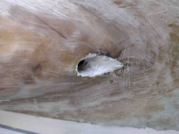
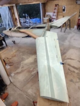
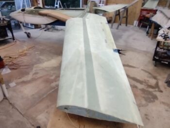
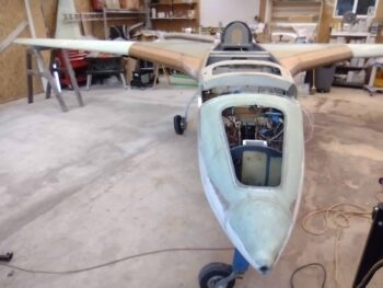
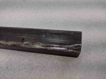
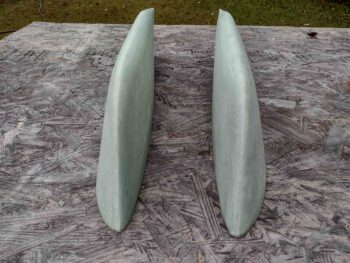
After returning back later this afternoon from my quick overnight trip to Raleigh, NC, I got to work sanding the left bottom winglet to allow for attachment and micro finishing.  I had missed a couple of spots on the right bottom winglet that I touched up as well.

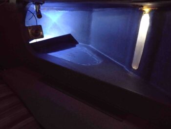
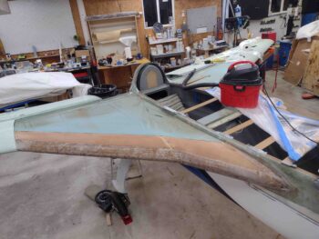
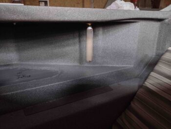
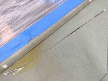
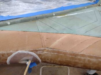
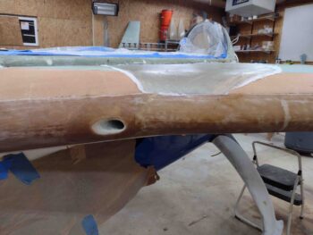
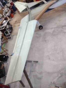
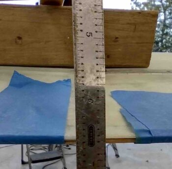
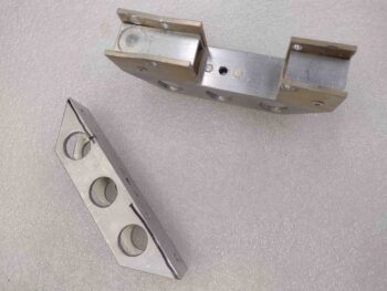
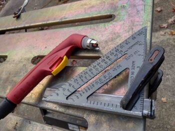
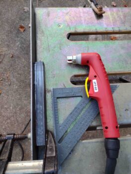
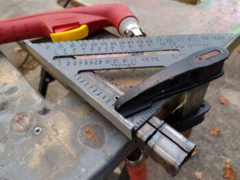
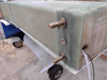
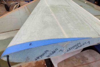
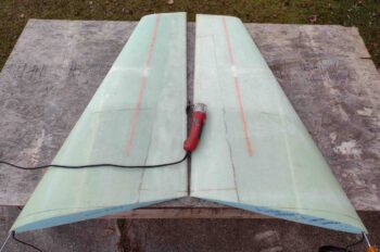
Here’s a front head-on view of the bottom winglets.

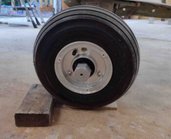
My next sanding task I intend to knock out this week are the wheel paints.

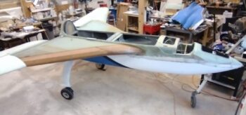
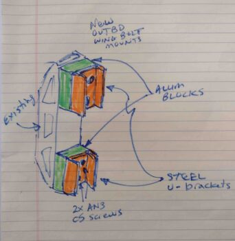
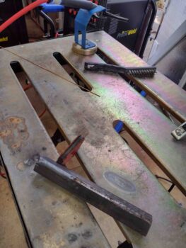
I need two things before I mount the wings back onto the bird: 1) Rework the internal CS spar wing bolt brackets for the outboard pair of bolts.  This is the wing bolt mod that a lot of EZ owners/builders do that have the wing bolts captured internally sticking out of the spar facing aft to make it EZ to put the wings on… especially with just one person.  Most bubbas use a low-profile piece of aluminum U-channel, but since I have to have a “bridge” to get over the internal cable conduit, I’m going to need a couple of 1″ square coupons of steel U-channel.  That will requite some TIG welding.  More to follow on that, which I plan to focus on tomorrow.

Item #2 is the MM-4/HM-4 rod ends that I need for the CS128 aileron control tube bell crank that came with 1/4″ bolt holes (I’ll note all the other components had 3/16″ bolt holes).  When I mount the wings I want to test out the aileron travel on each side and be ready to knock out linking up the entire firewall-aft aileron control system.

With delivery from ACS set for Tuesday, that gives me the next day and a half to get the welding knocked out before the MM-4s go in.  I plan on having the wings on Tuesday night, and start shaping the top strake skins Wednesday.  Then planning on having top strake skin layups complete by this coming weekend.

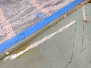
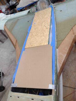
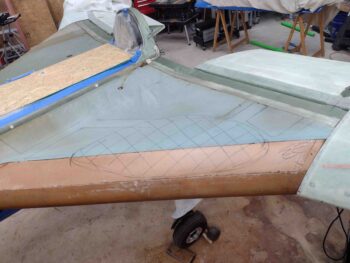
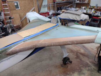
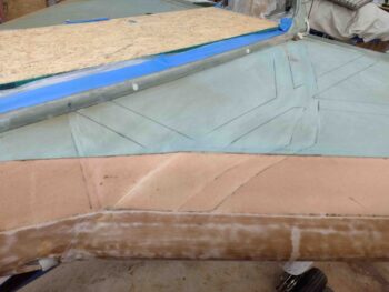
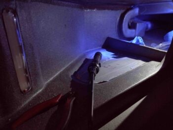
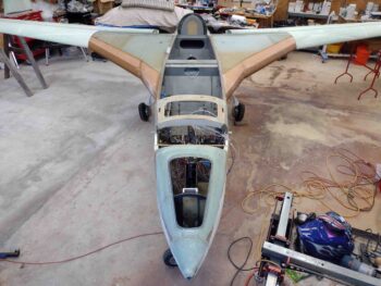
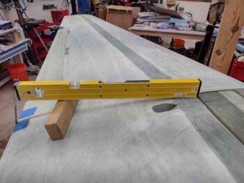
My next task after the strake top skins are glassed is mounting the winglets to the wings.  Not wanting to jump into the welding fray tonight, I finally decided to figure out the winglet lower template and get the bottom edge of the winglets trimmed in prep for mounting to the wings.

My first task was to find and mark the centerline of the upper winglets leading edge (no pics).

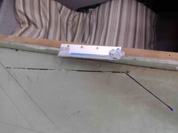
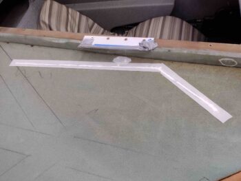
The next step per plans is to use the paper template from the plans and glue it to the inboard side, as explicitly stated in Chapter 20 of the plans.  I had grabbed a copy from a build buddy that has a real set of plans, since mine are the PDF version.  In my ignorance and naivety back in Germany early on in this build, I thought it was a template like all the others (canard, elevators, etc) so I put it on a piece of 1/4″ thick plywood.  Probably a good thing in the end since it survived all these years!

Now, in assessing this entire template fitting deal, my buddy Dave Berenholtz discovered that the template fit a lot better on the flatter outboard side of the winglet… obviously counter to what the plans say.  And we all know there are errors in these plans… they are not infallible.  Since I was using my wood template to make up blue tape template “appliqués” I decided to test Dave’s method as well as follow the plans.

OVERVIEW: If you set the pair of winglets upright in front of you looking at the leading edges, you would have 2 left sides and 2 right sides.  If you broke down, say the left sides (in relationship to sitting in the plane), one would be the inboard of the right winglet and the outboard of the left winglet.  Since I do everything exactly as Burt says to (haha!) my primary focus is on the inboard edge (plans method).  Thus as per my example I labeled my blue tape template “R” for the inboard right winglet (“primary”), but also used it on the outboard LEFT winglet (“secondary”).  Clear as mud?

Using my example above for the other side, the LEFT blue tape template above is applied to the right winglet’s outboard side (secondary).  I then marked the edge of the tape template and carefully removed it.

I then used the same LEFT template for its primary purpose, marking the left winglet’s inboard lower edge (primary).  After the tape template was in place I then marked the cut line and removed the tape.

Here we have pretty much my initial example in action.  The RIGHT blue tape template is applied to the outboard edge (secondary) of the left winglet… I then marked it and removed the tape (no pic).

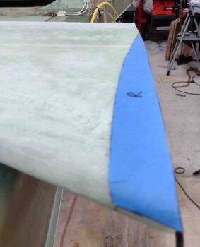
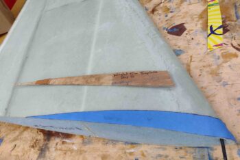
I then used the same RIGHT blue tape template and applied it to the inboard edge (primary) of the right winglet (note the leading edge centerline marks)….

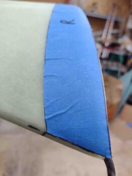
And marked the edge of the blue tape template onto the winglet with a narrow point Sharpie before removing the template.

Well . . . I could stair at these lines and wonder if they were right or not, or in my bull in a china shop fashion I could just cut the damn things.  As Tony Stark so aptly states in the Iron Man movie, “sometimes you gotta run before you can crawl!” … ha!

It was early evening and since it’s Fall here we lose daylight much faster now.  If I was going to cut these things today it had to be sooner vs later (unless I wanted a messy shop!).

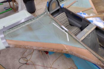
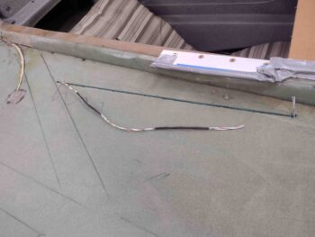
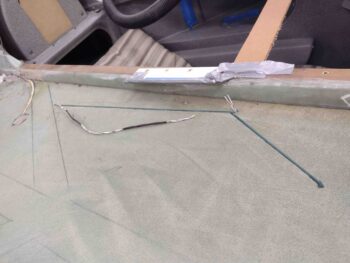
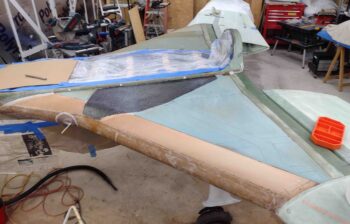
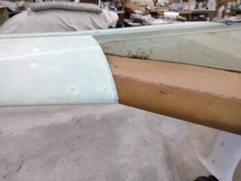
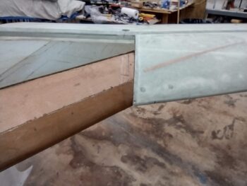
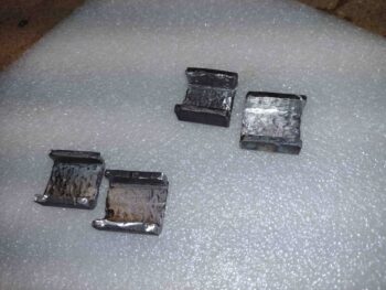
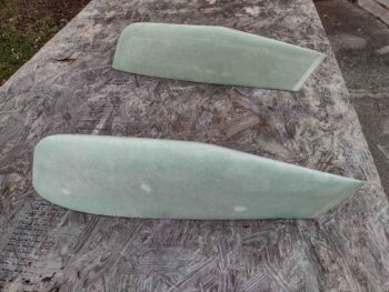
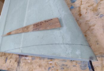
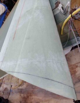
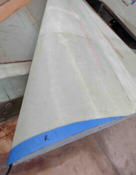
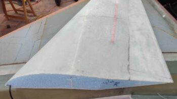
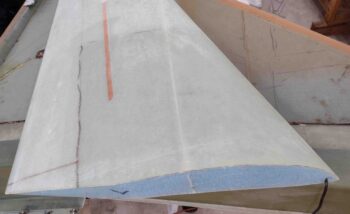
Here we have the marked pair of winglets, ready to trim the bottom edges to allow them to fit the wing tips.

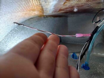
I put flat tip screwdrivers over the RG-58 radio antenna cables (shows you how long ago I started this project… I would have used RG-400 had I built these 6 months later than I did) to protect them.

I then used my ever-trusty Fein saw to trim the inboard cut line just below and inside the line on the right winglet.  With a little coaxing (pardon the pun) I removed the glass skin piece.

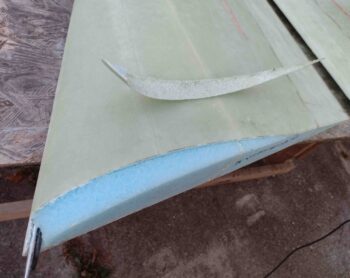
And then did the same thing on the left winglet.

I then slowly —in 3 phases— used my Fein saw to cut down into the foam, perpendicular to the cut line.  The real focus here is that inside line since the outboard side doesn’t have to be exact since it hangs out into air and doesn’t mate with anything other than the Block ‘A’ piece of foam and eventually the lower winglet… both trimmed to fit the outside edge, not vice versa.  Which is why I’ll note that the plans state, “Mark the trim line then saw the piece out (coping saw) sawing roughly perpendicular to the mark.”

Once all the foam was removed to the other/inboard side, I used a long 1/8″ drill bit to drill just slightly below (aka towards the original bottom winglet edge) the foam’s new rough contoured shape.  I then flipped the winglets over and drew the line along the top edge of drilled holes also using the marked template line as a general guide for the shape.  I then cut the outboard sides of the winglet bottom edges, before using a narrow sanding block to clean up the new bottom winglet surface.

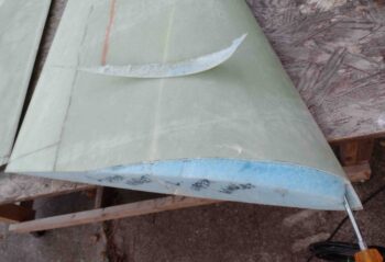
I’ll note that my resulting outboard cut line was about 3/16″ below the cut line of the outboard template, on both sides.  This tells me that using Dave’s method works fine (it obviously did for him!) with just around a negligible 3/16″ less height on the winglets… in my armchair engineering assessment!

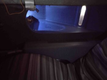
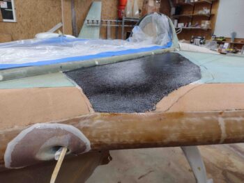
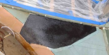
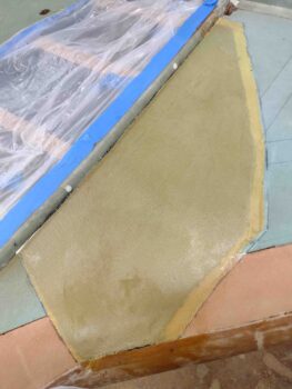
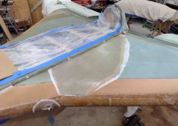
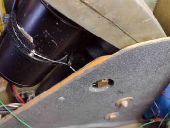
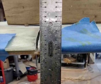
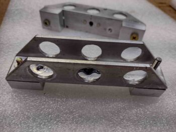
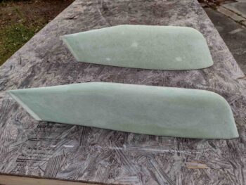
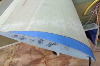
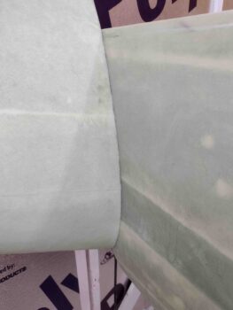
Here are some shots in the lit shop of the freshly trimmed right and left winglet bottom surfaces.

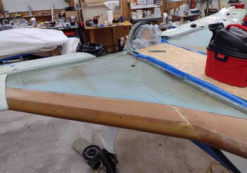
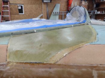
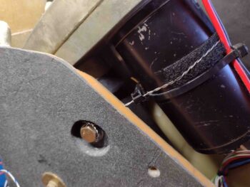
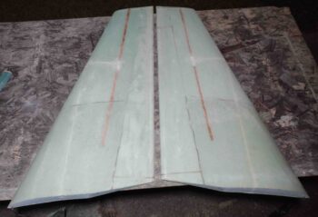
I did a quick check of the right winglet on the end of the right wing to see how my cut line came out.

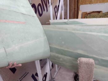
Pretty spot on considering I haven’t even really cleaned it up or sanded it smooth yet!

Now that my curiosity was abated on the lower winglet template fitment, I then propelled myself into another issue that I find somewhat perplexing with the build process on these birds.

BACKGROUND: LPC #131 in CP 49 is a mandatory ground plans change that mandates using 4130 steel control tubes for the ailerons aft of the firewall.  As an aside, I know some Long-EZs that are still running aluminum and that is a risk assessment we all must make. To be clear, I say that with zero judgement. Since I will have a titanium wing root cover plate I personally decided to go with aluminum CS129s inside the wing root, but where my control tubes are exposed I went with 4130 steel in line with this CP change.

But wait, there’s more.

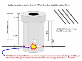
LPC #131 specifically addresses replacing aluminum components that are less than 0.1″ thick.  That’s why the aluminum CS128 bell crank and CS131 spacer are still used since they meet this requirement.  CP 50 provided further clarification on this plans change and gave more specifics for its implementation, including using “four (4) stainless steel pop rivets, such as Cherry #CCP-42.”

I will note that this last statement is easier said than accomplished in the real world.  I’ll also note —let me be clear that I AM NOT FRAGGING ANYONE!— that I still see a lot of folks with steel control rods and solid aluminum rivets… which I’ll point out are 1/8″ diameter so should technically meet the 0.1″ LPC #131 requirement, if it weren’t for the CP 50 SS pop rivet comment.

I will again state that I have no dog in this fight.  I am not a deputized member of the Canard Police Force that tells everyone how their stuff is not per plans and to proclaim 50 “hail Burt’s” for redemption…. I ask because I’m curious or will say something if it looks really dangerous. My notations and questions are ones of interest and curiosity.

Now, as any good military officer will do during Operational Planning, I’ve framed the problem as I see it.  If any of you have any other info or methods, please feel free to give me a shout.

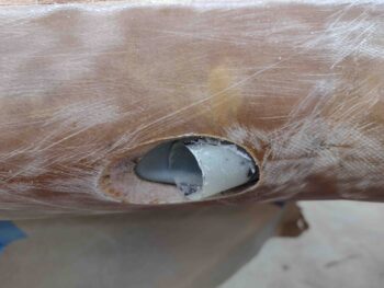
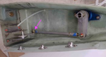
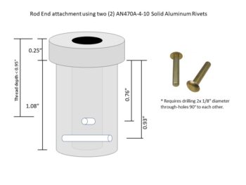
Here is my take on how we use solid aluminum rivets to mount a Rod End insert into the end of a control tube… EZ/PZ:

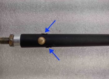
CP 50 states to use four (4) cherry pop rivets, #CCP-42s.  Ok, but hold the phone Bucko!  There is an inherent clearance issue here (remember, this is even before we went to 1/4″ rod end inserts!) in that one drilled through-hole with pop rivets going in at 180° out from each other has the first one going in fine, but the second one —although it will go in— does not seat 100% against the surface of the control tube.  Is this acceptable?  I guess that’s a personal choice. In my book not as a standard practice for every rod end getting installed.

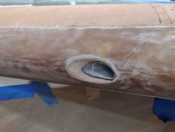
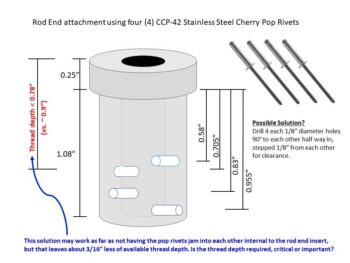
So how about if we offset every hole for all 4 pop rivets getting installed?  Well, we need 1/8″ between the holes (and with the way pop rivets flair internally that’s even a minimal clearance spacing… it’s tight).  Ok, so check this out.  Note how we eat up our available depth to thread the rod end into the insert.

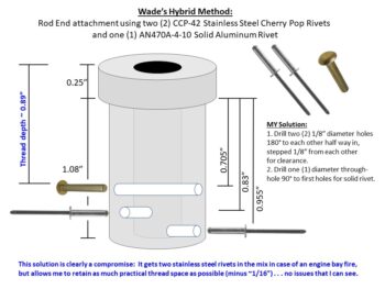
I’ve learned that in negotiations that compromise is actually the least beneficial to both parties… but here in the technical world I think it worked out ok.  This is my method of dealing with this internal clearance/crash issue with the pop rivets… I simply did a personal risk assessment and pressed forward.

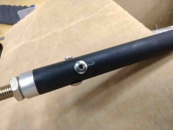
I’m using two stainless steel cherry pop rivets (CCP-42) and one solid aluminum rivet.  As I note in the graphic below, that gives me 2x non-melting securing points in case of an engine fire… and let’s be honest, those are not an overly common event.  I place this in the realm of remote possibilities, but let’s still be prudent and as safe as possible.  Right?

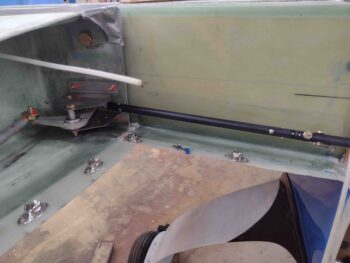
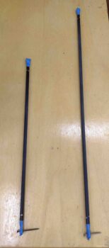
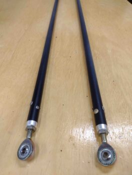
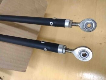
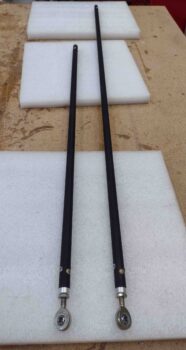
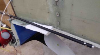
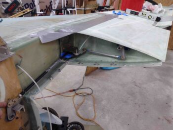
Here are my aileron control tubes —CS 125 & CS126— painted black with the rod end inserts riveted into place as per my hybrid method.  I’ll note that these are way longer than required and will be trimmed to length at final install, and the quick disconnect components installed to allow for EZ wing removal.

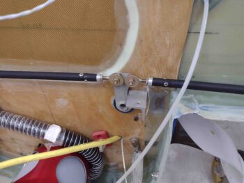
The firewall side ends have XM-3s installed since the CS124 pivot tab has holes drilled for AN3 bolts.

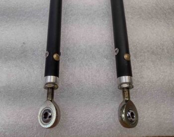
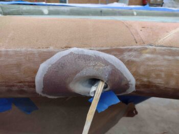
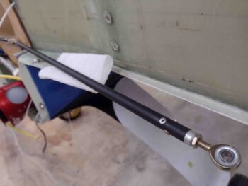
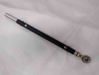
Here we have a side shot of the rivets securing the rod end insert.  Note the solid aluminum rivet facing the camera, perpendicular/90° to the stainless steel pop rivets that, while 180° apart from each other, are also stepped 1/8″ away from each other . . .  as is the aluminum rivet from the SS ones.

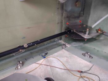
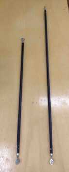
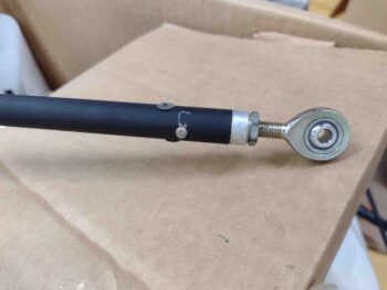
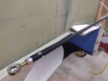
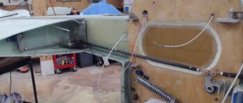
Here’s the longer left SC125 control tube test-fitted in place.

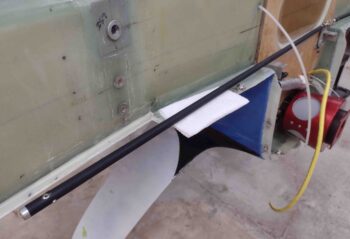
As well as the shorter right CS126 control tube test-fitted in place.

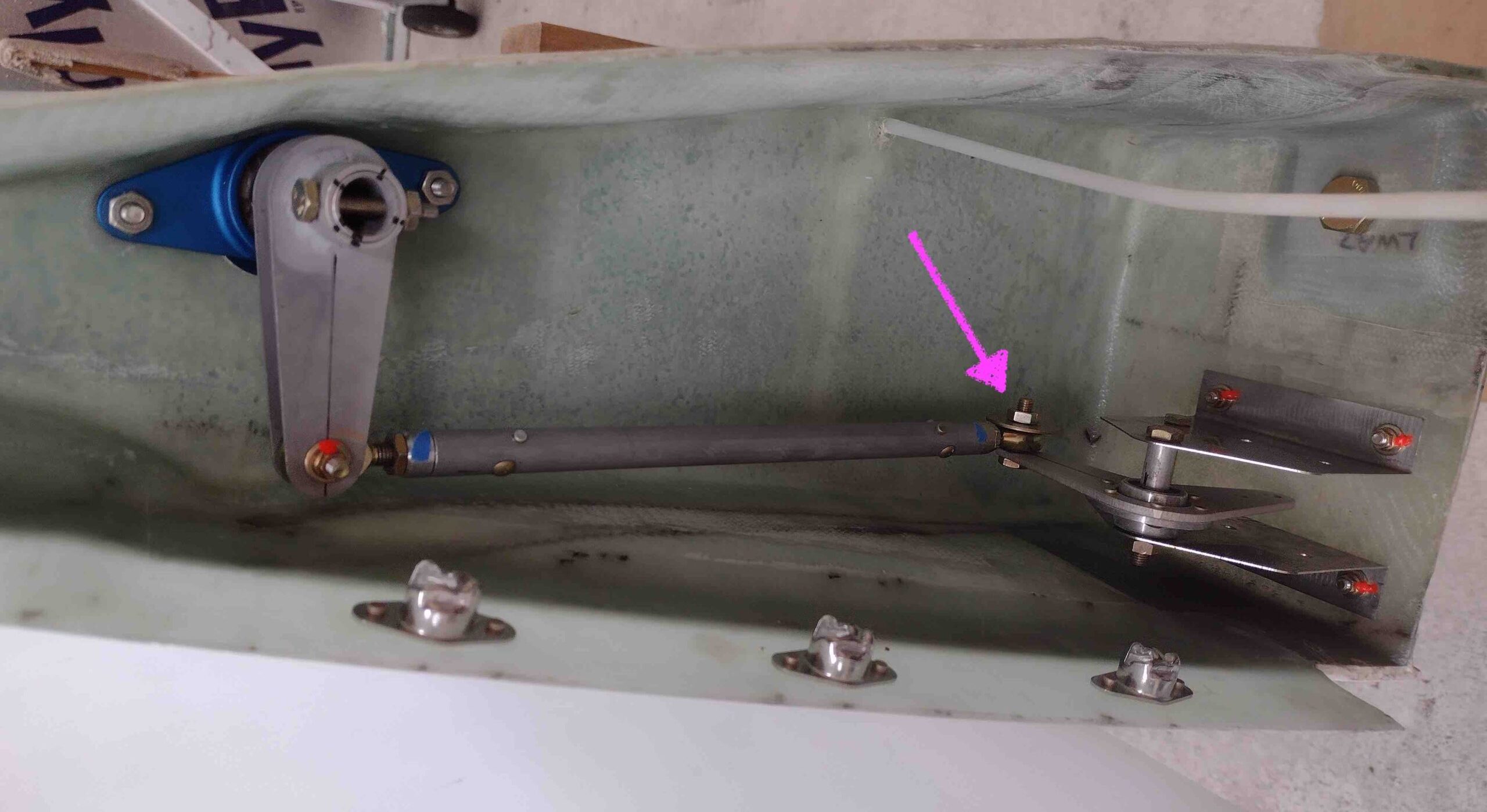
And both control tube rod ends secured to the CS124 pivot tab with AN3 hardware and wide area washers.

Knowing I had a fairly lengthy task of getting all these explanations and examples in this blog, I called it a night!
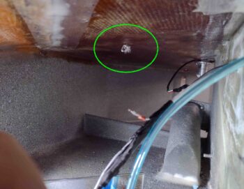
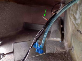
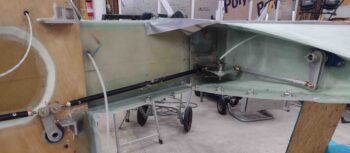