Chapter 16/19/20 – A bit o’ stuff done

I started out today by swapping out the temporary nuts on the bolts securing the CS127 brackets to the aircraft grade nuts to make the install permanent.

I then knocked out a seemingly sideline task of aligning the trailing edge of the ailerons with the trailing edge of the wing… that seem to get askew once the aileron is cut out of the wing and remounted,

Here’s the inboard aileron trailing edge seam with the right wing, before and after I sanded down the wing to bring the edges into alignment.

Here’s a view down the trailing edge of the right wing.

I then did the same on the left wing.

The outboard edges weren’t that bad, and with some minor sanding were back into alignment.

I then rounded up my CS125 and CS126 aileron control tubes that connect the CS128 bell crank to the aileron control tab on the firewall.  There was a tad bit of surface rust on the 4130 steel control tubes after all these years, so I decided to do a bit of corrosion control and prevention.

The first pic on the left is the raw aileron control tubes.  In the middle pic the shorter tube has been sanded and cleaned up, whereas in the last pic on the right both control tubes have been sanded, cleaned up and acetone-wiped for painting.

I started to prime the aileron control tubes with Zinc Chromate, but I guess the paint can had gone bad since after a couple of passes it just wouldn’t fire anymore.  I tried with no avail to get it to shoot but no joy,

So I brought the partially primed control tube back into the shop and cleaned off the Zinc Chromate I had shot onto it.

I then grabbed my trusty can of Rustoleum self-etching primer and hit the tubes with that (left pic).  After a good hour-plus cure I then shot the control tubes with flat black exterior automotive paint…. which cures to full hardness in 48 hours.


My last task of the evening was taking the right lower winglet outside and sanding it in prep for further glassing and micro finishing.

Tomorrow will be a light build day since I’m leaving mid-day for Raleigh to attend an overnight Halloween party with Jess.  Upon returning I intend to upgrade my CS spar wing bolt brackets and get the wings installed in prep for shaping and glassing the strake tops.


Chapter 19 – Wings officially complete!

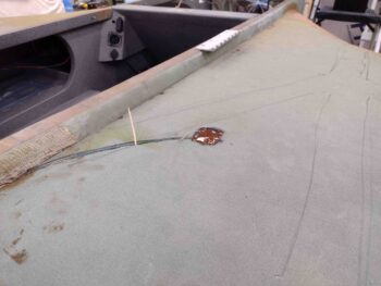
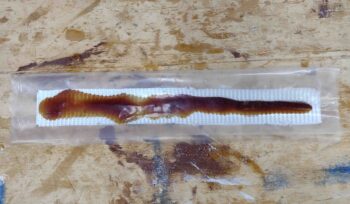
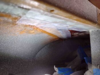
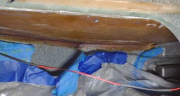
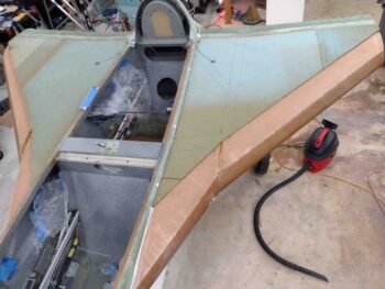
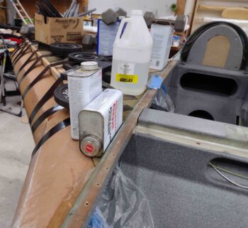
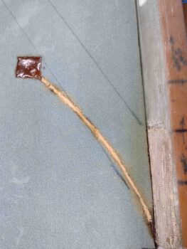
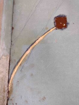
I started out today by whipping up some dry micro using EZ-Poxy and filling in the remaining gaps in the fuel probe wire channels on the tops of the strakes.

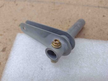
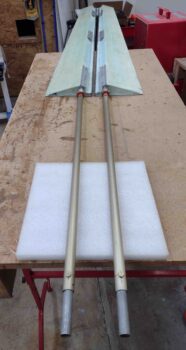
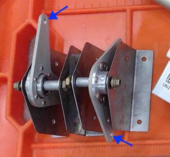
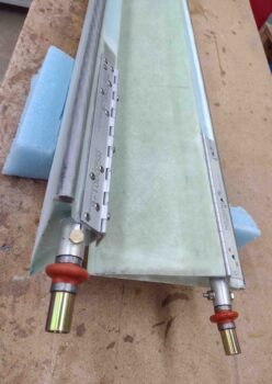
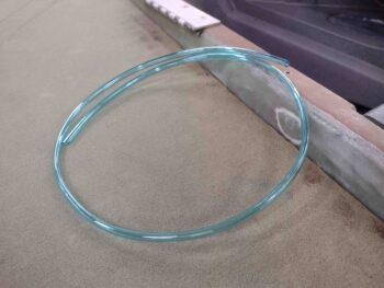
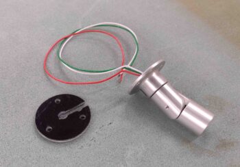
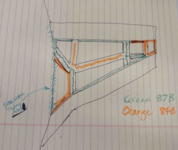
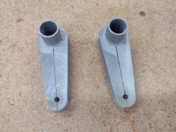
I then grabbed my CS132 weldments and marked the center line on each part.

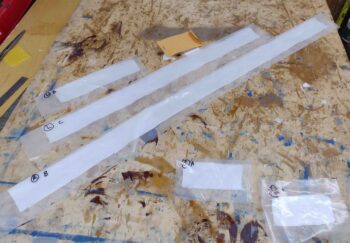
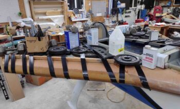
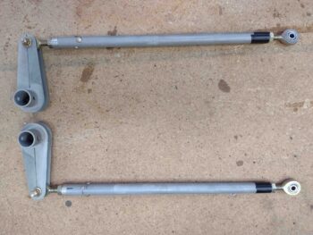
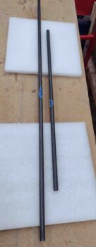
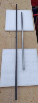
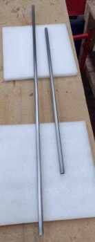
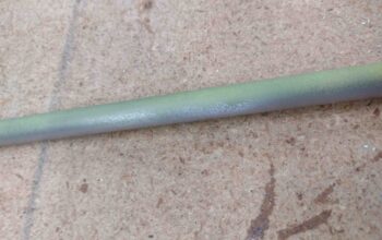
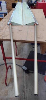
I spent a good little bit of time riveting up one side of the CS129 control tube, for both wings, and then taped the other rod end insert into place since I wanted some wiggle room on determine the final length of the CS129 tubes.

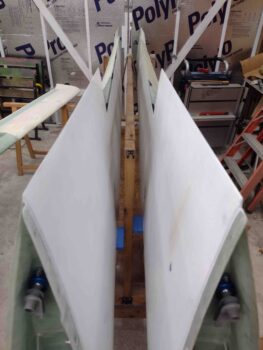
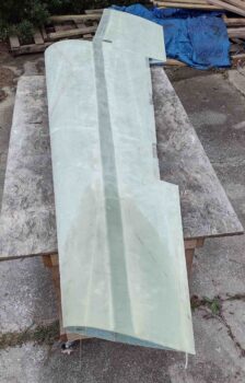
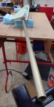
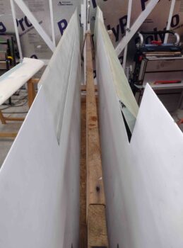
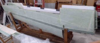
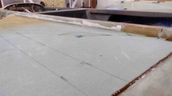
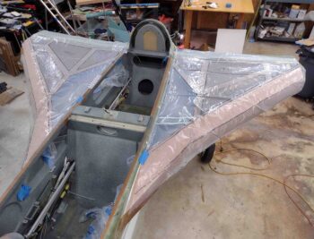
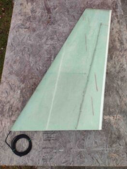
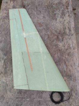
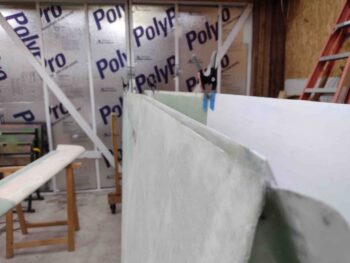
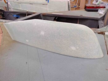
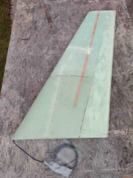
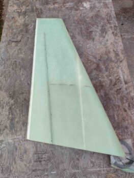
I had to run out and get some errands knocked out, and I returned later in the afternoon.  While it was still light out I sanded the left winglet (about an hour) to prep it for install, subsequent glassing and micro finishing.  Next up on the sanding docket will be the lower winglets.

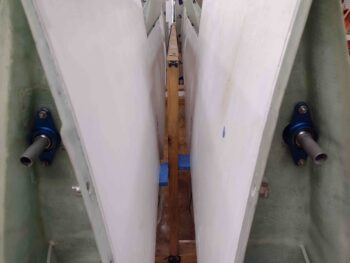
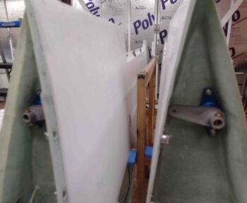
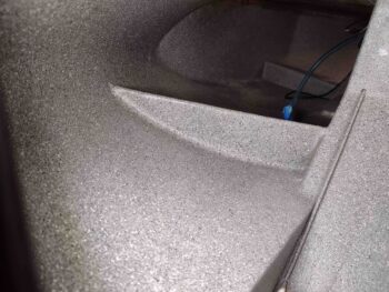
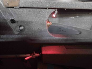
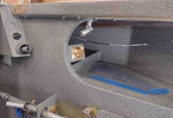
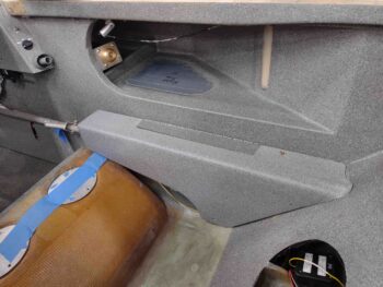
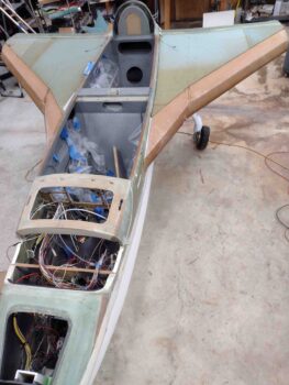
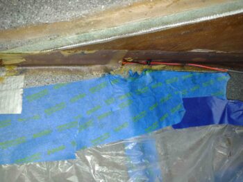
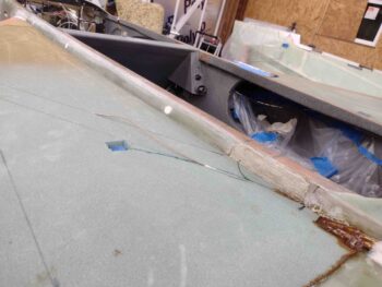
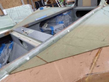
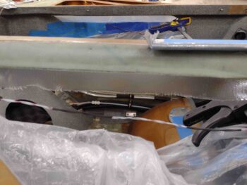
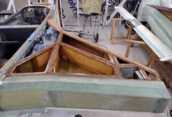
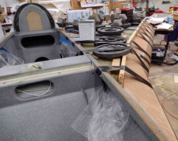
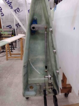
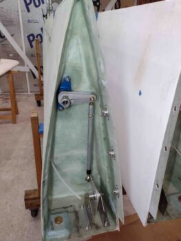
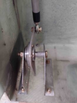
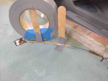
I then got busy installing the wing aileron control system components.  As I was working the initial task of determining the 90° angle between the CS132 weldment and CS129 control tube, I set the CS128 bell crank and brackets in place (bottom of pic).

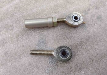
On the recommendation of Wayne Hicks in his write-up, I had also left my CS129 at 9.3″ vs the plans 9.1″ to ensure I had enough length if required.

Well, I could tell that my CS129 was way longer than it needed to be… something didn’t seam right.  I did a little looking in the plans and realized that the original rod end inserts did NOT have the 0.2″ tall end caps that the new ones do.  So with 0.2″ extra on each end plus my 0.2″ inches for some wiggle room on length, I was sitting at a minimum of 0.6″ too long on the CS129.  Even with the rod ends bottomed out I was too long to have any semblance of getting the required 90° between the CS132 & CS129, or the next 90° between CS129 and the CS128 bell crank.

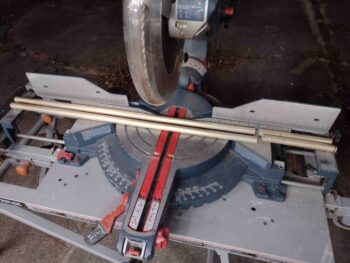
I trimmed my CS129 control tubes down to 8,5″ each and pressed forward.  Although the rod ends are still threaded in more than what I would think is “normal,” I could at least dial in the required angles with these components in the wing root.

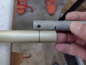
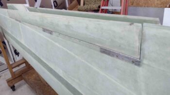
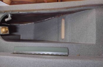
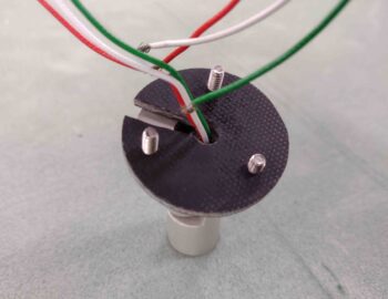
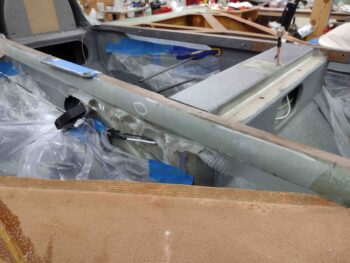
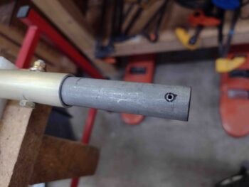
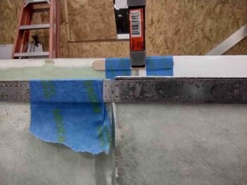
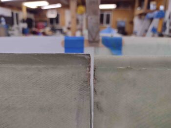
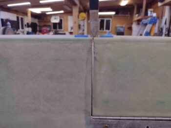
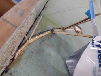
[Note the hash marks on the end of the CS152 tube aligning it to CS132]

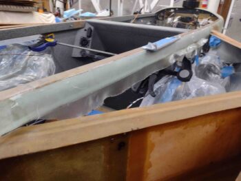
Again, although I was focused initially on the 90° angle between CS132 and CS129, I worked the angles as a system to keep the CS129 tube distance off the rib wall consistent and the angle of CS129 with the lower inside wing root surface consistent as well.  And before finalizing the CS132 to CS129 right angle, I also made sure the CS129 to CS128 90° angle was fairly close to final.

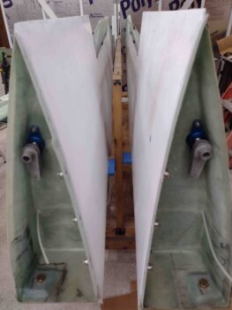
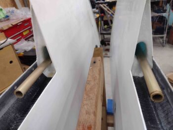
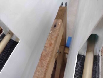
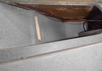
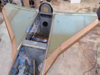
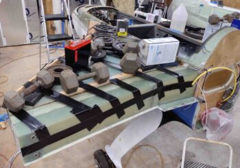
I’ll note that keeping these 90° angles on track resulted in pushing my CS128/CS127 bracket assembly more inboard and further down than I saw in plans or other builders’ installs.  I worked it for a good bit to make sure I wasn’t screwing anything up, but given the components I had on hand while maintaining those two 90° angles drove the placement of CS127 brackets to where they are in these pics.

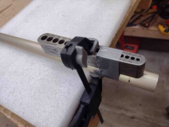
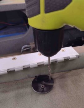
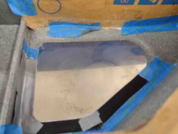
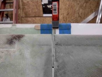
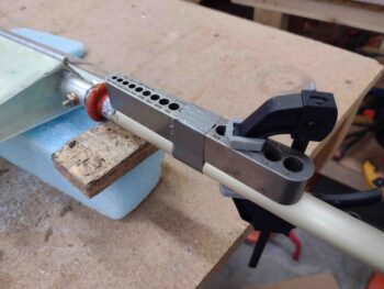
After ascertaining the right wing’s CS132 right angle with the CS129 control tube, I removed the aileron assembly and then subsequently removed the CS151/CS152 combo off the aileron.  I hand drilled the top marked bolt hole into CS152 that would be used to attach CS132 to it.

The hole through CS132 was not straight, and being offset a hair required me to hand drill the holes on each side separately… and when I say “hand drill” I mean without the use of my tube alignment block that I normally tape and clamp to a tube to get a near-perfect straight and centered hole.

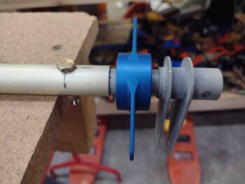
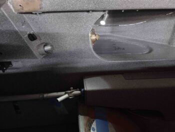
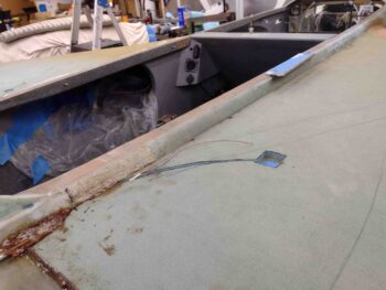
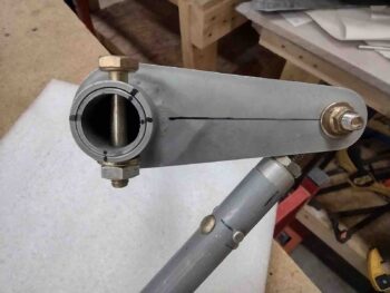
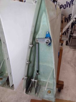
Here we have the right wing CS132 bolted to the CS152 tube, thus connecting the CS132/CS129 components to the aileron…  another significant segment added to the linkage (yes, here my clocking marks are off by about 0.015″ and while not perfect, were a good bit closer when the bolt was fully seated and tightened).

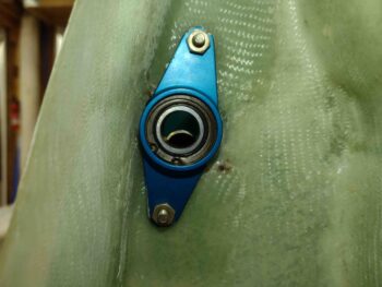
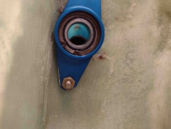
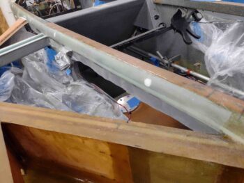
I reattached CS151/CS152 to the aileron and then reinstalled it into the right wing.  I then bolted the CS132/CS129 combo to CS152 that enters into the wing root area through the root bearing.

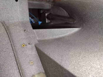
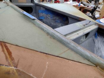
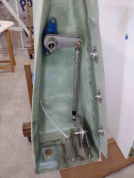
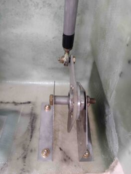
My next task was dialing in the 90° between CS129 and CS128.  While doing this, I slowly started securing the CS127 brackets into place by drilling out the bolt holes and securing the CS127 brackets in place as I kept verifying the 90° angles were good.  I will note that the third bolt that went in knocked my CS132-to-CS129 right angle off a degree or two, but in assessing this setup I just chalked it up as the cost of doing business… I don’t think I’m going to get much closer than that.

Now, I’ve blathered on about focusing on my two plans-required 90° angles inside the wing root… and as any military planner knows all plans may be perfect up until first contact with the enemy.  A primary goal in this setup is to have 20° up-travel on the aileron that is noticeably ensured when the CS128 bell crank hits a hard stop bolt across the CS127 brackets.  I was getting that until I secured my last couple of mounting bolts on the CS127 brackets —even though they were clamped tightly in place while I set the component configurations.

It took me a good 45 minutes of slowly dialing in the rod end in/out threaded length and thus negating my oh-so-conscientious focus of nailing the CS129/CS128 90° angle.

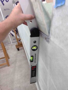
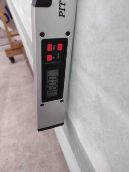
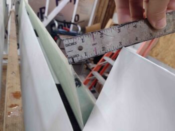
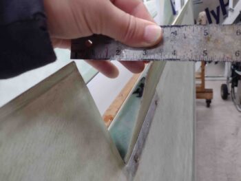
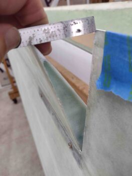
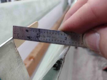
To get my 20° aileron up travel (above… 180-160 = 20) —which equates to a hair over 2″ swing/gap between aileron trailing edge vs wing trailing edge— I had to come off my CS129/CS128 90° angle by an estimated 2-3°.  Again, the cost of doing business IMO.  If anybody out there has any insights or a better technique, please let me know.

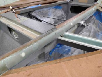
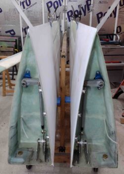
I then repeated the whole affair on the left wing.  Being better mentally prepared and knowing how to initially set everything up fairly close to my final configurations not surprisingly made this exercise go much quicker and smoother on the left wing.

After all the aileron control components were installed on the left wing, and with again needing to sacrifice a degree or two off my near perfect CS129/CS128 90° angle, I was seeing almost 21° on my aileron up-travel and 2.1″ gap between aileron and wing trailing edges.

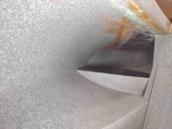
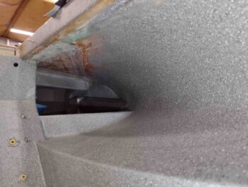
I’ll note that the last half inch up travel on my left aileron is marked with the inside bolt squishing into the interior wing foam… so I still have a bit of house cleaning on the inside of that channel to accomplish.

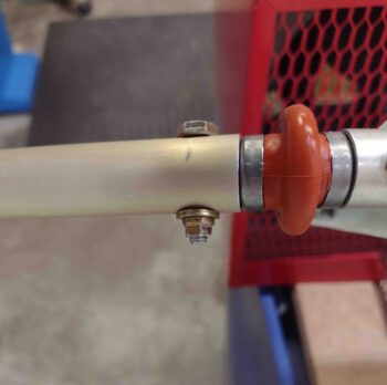
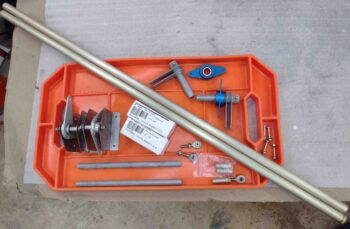
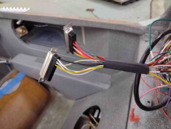
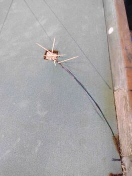
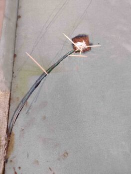
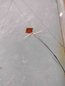
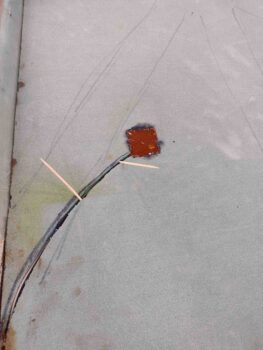
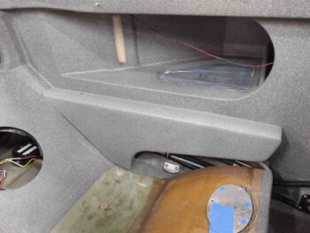
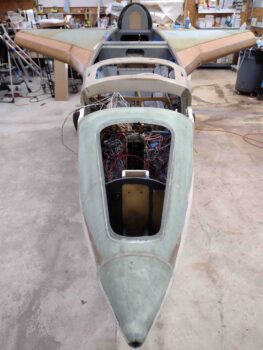
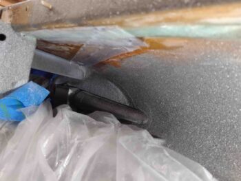
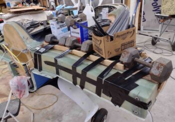
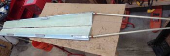
Early next week I’ll receive, mount and dial-in the MM-4 rod ends at the CS129/CS128 connections, where the black electrical tape is currently and temporarily securing the rod end adapters in the pics below.

It was quite late, but excellent progress on the day.  Although I do have a couple minor tasks to complete, I can finally say that I’ve finished Chapter 19!

As par usual, I headed in for a late dinner and to check over my notes.

Chapter 16/19 – Rigging Aileron Controls

I started out this morning by whipping up some EZ-Poxy dry micro with E-Z 87B hardener and laying it into the fuel probe wire channel on each strake top.  I have taped-up stir sticks and toothpicks in place to secure the wires at the bottom of each channel to keep them as far away from the surface as possible… for when I eventually sand the foam tops of the strakes, pre-glassing.

I then got busy drilling out the outboard ends of each CS151 aileron torque tube to allow me to bolt it to the aileron Universal Joint.

I got both CS151 aileron torque tubes drilled and bolted onto the aileron U-joints using the plans called-for AN3-11A bolts… more on those below.

A wide angle shot of the CS151 aileron torque tubes bolted to the ailerons.

I then took a “break,” grabbed my right winglet and sanded it outside in front of my shop. It cleaned up nicely and is now ready for install, subsequent glassing and micro finish.  I plan on sanding the left winglet tomorrow.

I

I’ll first digress for a bit in saying that while I was in the Air Force I was part of a number of multi-month/year long deployments, exercises, etc.  An odd feature that us deployed bubbas recognized was that things were bearable up until the last few weeks of the deployment.  When you know that you’re rotating back stateside in just a mere few weeks, things that you dealt with for a year suddenly became irritating as all get-out. The closeness of normality just out of reach caused all the idiosyncrasies of the current crappy situation to magnify all the crappiness of each little thing.

So just maybe I am getting really close to finishing this bird, because my irritation level for seemingly unwarranted BS is pinging rather high.

Now, I’m not trying to make this ‘Bash Cozy Girrrls’ week or anybody else, but another issue that Ary pointed out on his blog was that the CS152 through-root-bearing-tube      —that attaches the CS132 weldment inside the wing root to the CS151 aileron torque tube inside the inboard wing channel— comes pre-drilled and set inside the CS132.

The issue is that per plans the CS132 must be set at 90° to the CS129 control tube WHILE the aileron is at 0°.  If the aileron/CS151 combo is installed and the aileron secured at 0°, then setting the CS132 weldment at 90° to the CS129 needs to all occur inside the wing root… in other words, the variable being manipulated needs to be the CS132 placement (clocking) onto the CS152 tube.

With the CS152 pre-drilled and attached to the CS132 weldment, this variable is now moved BEHIND (read: out of sight) the wing root bearing at the CS152 attachment point to CS151.  Clearly this infuses a level of complexity that could very easily result in aileron control system components being misaligned… Ary solved this issue by simply using another piece of tubing for the CS152 tubing and eliminated the pre-drilled issue that way.

Having more time to ponder on it, I simply decided to reverse the CS152 tube and pre-mount it to the CS151 aileron torque tube.  This moves the CS132/CS129 90° angle finding exercise back into the wing root and puts the CS152-to-CS151 as a known quantity (aka ‘constant’).

[As a point of note and to be fair, I wasn’t sure if I was missing something so I talked to Chrissi about this exact issue a couple months back… with no real resolution.  We had a long conversation about a multitude of other things and I am truly extremely fond of both her and Randi… but these build issues still need to be dealt with and addressed, IMO].

I measured the width of the wing root bearing, the attach tube portion of CS132, the 1/4″ spacing on each side of the wing root bearing, and the remaining portion of the CS152 tube that would be left to insert into the inboard end of CS151.  I then marked CS151 for drilling.

And prepped CS151 for drilling to mount CS152.

Once I drilled CS151 and bolted CS152 into place, I test-fitted the wing root bearing and CS132 into place to get a visual on if my measurements were correct.  They were… Bingo!

Here we have the CS152 4130 steel tubes bolted into the inboard ends of the CS151 aileron torque tubes using the plans called-out AN3-11A bolts… again, remember these bolts!

Why remember these AN3-11A bolts?!  Because they are TOO friggin’ long!!!! At least for my set up.  When I finished out the wing aileron cut out shear web I naturally overlapped it into the entrance of the channel where the CS151 runs inboard to the wing root rib.  Well, the AN3-11As are so long that on my right aileron it literally locked the CS151 into this channel and in forcibly removing the aileron I inadvertently dinged one edge.

I hadn’t yet put the left aileron/CS151 combo into the left wing yet, so I immediately swapped out the two AN3-11A bolts for the only two AN3-10A bolts I had on hand… and yep, 2 threads showing!

Even then I had clearance issues with my left aileron inside that channel.  Not nearly as bad as the right side.  When I pulled out the right aileron I lopped off that excess crap with my Dremel Tool.

Now, my wing cores are Feather Light, so I am not entirely sure what is going on… since 1-2 plies of BID inside the entrance to that aileron torque tube channel shouldn’t be causing such hate and discontent with these bolts… but it is/was.  And I can’t imagine I’m the first builder to have this issue.

Regardless, I shoved my Dremel Tool cutoff disk down into the opening of the channel and ground away the interior glass to remove what was the glassed wall of the channel —again, just a few inches into the channel— to allow clearance for these damn bolts!

After this round of playing Johnny F— Around in my naivety of following the plans (I’ll note those bolts just looked way too long when I installed them) and correcting even more needless BS, I then installed the aileron/U-joint/CS151/CS152 assembly into each wing, capped off by then mounting the wing root bearing with CS152 exiting into the wing root as it should.

I then set the CS132 weldments in place.  Tomorrow I plan on getting those, the CS129 control tubes and the remaining wing root aileron control tube components mounted.

I’ll further note that I checked the swing of the ailerons and for each wing the minimum I’m getting from aileron trailing edge to wing trailing edge is about 2.25 inches.

And with that, I closed up shop to have dinner and a well-deserved libation.

Chapter 16/19/25 – Aileron control tubes

In preparation for installing the aileron control components in each wing, I am reviewing and assessing how my fellow builders accomplished this task… mainly Dave Berenholtz and Ary Glantz, both very talented builders in their own right.

In reviewing Ary’s excellent write-up on his blog I came across an issue that was hiding in plain sight.  I’ll start by stating emphatically that I love the Cozy Girrrls, Chrissi and Randi, and all they’ve done for this community.  But I have to say in all honesty that I’m disappointed in the info I just unearthed on Ary’s write-up concerning the aileron control system CS128 Belcrank that they sell.  As innocuous as it may seem, their belcrank comes with 1/4″ holes on each arm for attaching the control tube rod-ends.  On the surface no big deal, but it’s definitely causing me headaches in time, money and effort . . . read on.

Without doubt using 1/4″ holes here is in line with the plans changes in CP 102 and CP 103 to increase the size of the rod ends from 3/16″ to 1/4″, at least on the face of it. And maybe using 1/4″ rod ends is a standard in the Cozy world.  However, after this mod hit the streets and Long-EZ builders, fliers, and/or owners were tasked with converting their rod ends, Rick Girard, Ken Miller and others discovered a little gem sold at Wick’s Aircraft: the XM-3.  In Rick’s words:

“First thing is, do not use HM-4’s. Wick’s has a rod end that has a 3/16″ hole in the ball and is in every other way equivalent to the HM-4. This will save having to drill out all the bell cranks. Wick’s part number is XM-3 (I know it doesn’t make sense unless the dash number spec’s the hole in the ball, but it is a 1/4-28 thread).”  Read here, page 22.

I followed suit and bought 8 of the XM-3 rod ends for the aileron control system.

And now I’m following suit after reading Ary’s blog and buying four Heim HM-4 rod ends in a scramble to get the aileron control system installed.  To be fair, the CS128 listed on the CG site does state it uses MM-4 rod ends, but it would have seriously made life way easier for a number of builders if these were produced with 3/16″ holes to then allow HM-4/MM-4 users to simply take a minute to drill them out to 1/4″.

I’ll know and assess more when I get the 1/4″ rod ends in hand, but looking at Ary’s write-up the kicker isn’t really even the requirement or cost to get these new rod ends: it’s the resulting lack of clearance with them installed.  Ary stated that he had to rewicker the configuration of the Belcrank in the CS127 brackets by trimming down the CS131 spacer and adding washers below the Belcrank to reposition it higher simply to add clearance for the bigger AN4 bolt heads.  Now we’re getting into make-work on a supposed off-the-shelf part… which is quite frustrating to a project manager like myself.

I thus fired off an order to Aircraft Spruce for these new rod ends and a few other parts.

Moving on.

I’d say I took my frustration out by sanding the top of the left wing in prep for micro finishing it, but let’s be honest: sanding sucks.  As on the right wing, I spent about 2 hours getting a good dull finish on the top surface of the left wing.  The good news is that I plan to follow Wayne Hick’s lead and peel ply the top strakes when I glass them, which only leaves the winglets as any major area to sand remaining… as far as fiberglass.  Obviously lots of micro-sanding left in my future!

After a bit more research, confirming task sequences, etc. I dove into the initial steps of installing the aileron control system components.  Again, pulling from other builders (a shout out again to both Ary and Dave), my overall plan falls in line with Wayne Hicks specific suggestion to start from the aileron itself and install inward towards the firewall (which is fairly in line with the plans method as well).

I first positioned, drilled and bolted a MS20271 B10 Universal Joint into the A10 tube on each aileron.

Over on the actual wings I mounted the wing root bearings then slid the CS152 tube with the CS132 weldment bolted to it into each bearing.

I then took the CS151 aileron torque tubes and slid them into place over the CS152 tube and pressed up against the internal face of the wing root bearing.

I then made a mark on each CS151 even with the inboard edge of the wing aileron pocket.

With that, I subtracted the distance of the aileron A10 nub and (now) added U-joint, which is 1.9″.  I also needed to remove another 1/4″ for the space identified in the plans that needs to be between the end of the CS151 tube and the wing root bearing face.  With my measurements calculated and marked, I then trimmed both CS151 aileron torque tubes to length.

And then temporarily mounted the CS151 torque tubes to the inboard nub of the Universal Joint using electrical tape.

I then carefully mounted the ailerons onto the wings with the CS151 torque tubes temporarily attached.

I removed the CS152/CS132 setups out of the wing root bearings to allow me to see the end of the CS151 aileron torque tube inside the bearing center hole.

Here we have a view of the CS151 aileron torque tube inside the hot wired inboard wing channel.

I measured the gap between the inboard edge of the CS151 aileron torque tube and outboard face of the wing root bearing on each wing.  On the right side I’m right about at a 1/4″ gap, while on the left it’s a little shy at 0.214″… so I’ll shave just hair more off the left CS151.

I also noted another issue when remounting the ailerons for the first time after having laid down primer and paint on the bottom surface of the wings: my gaps between the inboard aileron edge and wing aileron notch is essentially AWOL on the forward side of the aileron.

On the right wing you can see it needs some cleaning up to regain the nice gap I had… at this point the aileron is pretty much locked into place as far as any movement.

Over on the left wing I removed the aileron and trimmed the inboard edge to allow freedom of movement, although it started out looking pretty much like the right aileron did above. It was getting quite late so with the left good I decided I’ll fix the right aileron tomorrow.

I will note that I’m happy with the initial aileron swing of 3″ each direction, showing that even with the CS151 torque tube installed that the opening of the inboard aileron pocket is plenty large enough to allow for freedom of movement.  How this plays out once all the components are connected up remains to be seen!

And with a long day under my belt I called it good and headed in for a late dinner.

Chapter 21/22/25 – Strake glass prep

Now the prerequisite tasks are all focused on glassing the strake top skins.  Although that being said, I have some personal preferences in what I’m calling prerequisite tasks and the order in which they are completed.

The bottom line is that the wings need to be mounted in order to finalize the shape of the strakes and the interface between the outboard strakes and the wings.

Thus, I started out the first couple hours this morning getting organized and planning for the next steps in this build.  I want to have Chapter 19 – Wings completely closed out as I start on the final glassing of the strake tops.  While I glass the strake tops I’ll also start the process of attaching the winglets.

To finish out Chapter 19 I need to rig the aileron controls between the aileron and the wing root rib area.  I gathered up all my aileron control components and got them ready for install.

I then took the right wing outside and spent about 2 hours sanding down the top of the wing in prep for finishing.  I plan on doing the left wing top tomorrow.  Then the winglets probably the day after that.

After taking a break from the seemingly endless sanding on the right wing top, I then opened my package from Mountain High Oxygen: 3 foot length of blue oxygen tubing.

The routing was of course a bit more involved than anything should be, but after about half an hour I finally got the new Mountain High blue oxygen tubing ran from the left to the right strake, via the pilot’s seat back cap… ready to be connected up to the O2 bottle’s regulator and the Y-splitter for the pilot and GIB cannulas.

I then spent another half hour swapping out the wires from the old GRT EIS-4000 engine management system D-Sub connector to a new one.

Again, the old one had a socket position that simply wasn’t securing one of the sockets in place.  So far I don’t see any issues with the new 25-socket D-Sub connector.  This task is done and off the list!

Again, tomorrow I plan on sanding the other wing top in prep for both mounting them to prep and shape the top strake skins, but also to add the winglets to and be ready to finish at any time.

Chapter 21/22 – Fuel Probes Installed

I started off this morning checking the mode my fuel probe electronic control modules are running in… to do so you need to hold down the button and look at the 3-LED bank to ascertain what mode it’s in.  The 3 constantly lit LEDs tell me that these modules are operating in the 5S (set point) mode, which means it will be expecting me to program EMPTY, 1/4, HALF, 3/4 and FULL fuel level set points.

When I queried Nick Ugolini on which mode is best for my Grand Rapids EFIS/Engine Management system, he told me that 2S is the best for GRT.  The 2S mode is looking for basic EMPTY and FULL fuel level set points, and then the other fuel levels can simply be programmed in the GRT EFIS software.

To swap from the default 5S mode to 2S mode, the yellow data wire out of each fuel probe electronics module must be grounded before the sequence to switch the set point mode can begin.  And although my fuel probe electronics modules are just inside the GIB back seat access hole, they are wired up all the way to the GRT EIS-4000 25-pin D-Sub connector residing in the GIB headrest.

I pulled the cover off the headrest to reveal somewhat of a rat’s nest of wires, but found my 2 wires in a matter of seconds.  As an aside: I actually discovered that my current 25-pin D-Sub connector was unable to hold one of these data wire D-Sub sockets securely in place, and the entire connector will need to be swapped out.

With the data wires grounded, I proceeded to follow the steps to swap the fuel probe electronics module into the 2S mode.  This is denoted by the outboard LED lights constantly on, while the middle one flashes red.  I grabbed a few pics to get one showing the middle LED light “blinking” … step one complete: now in 2S mode!

I had gone to the airport earlier today to grab a gallon of 100LL.  The weather today was light rain which was perfect since the airport was very slow and I was able to get right in to get my AVGAS.  I then stopped by my local convenience store to pick up some Corona Lights to use as my requisite fuel container <wink>.

I pre-calibrated my fuel probes one side at a time by starting with just enough fuel in the bottle to have the tip of the probe just barely into the 100LL.  Note that I’m using a wooden disk to secure the probe so as not to have anything conductive touching the probe and potentially throwing off the reading.

The initial EMPTY fuel level set point takes about 16 seconds to process, whereas the FULL fuel level set point is finalized in just a couple of seconds.

With the fuel level set points programmed into the electronics modules, I then got busy physically wiring up the fuel probes.  I had pre-terminated the included ground ring terminals on lengths of wires to connect to the wires exiting out of the CS spar… in my rushing around to get the probes installed, I had mixed up these wire leads on the left and right probes, so just the wires coming off the probes are actually the color of the opposite side.  No big deal, especially since these will get buried in the foam and no one will know except you and me… shhhhh!

I had meant to switch the wires back to the correct side, but didn’t realize the wire color swap again until after I had cut this wire to length to splice and solder it in place.  Oh well… again, it will all get buried and works.

Here’s the left fuel probe ground wire spliced and soldered.

And the left data wire cut to length and soldered to the center sensor probe.  The left fuel probe here is ready to be floxed into the strake skin, as is the the right fuel probe in the second pic below.

Using somewhat dry flox, I placed it around the perimeter of each notch in the strake top foam… the goals here are to keep the flox from squeezing through the hole and clogging up the vent holes at the inside top of the probe, to seal the edge of the probe base plate to keep the later wet potting flox from seeping into the tank and thus potentially clogging those vent holes, and of course securing the fuel probe in place.

I kept the probes down in their respective notched holes with toothpicks and left them to cure for a few hours.

While the fuel probe flox was curing, I fired up the fuel site gage LED lights and turned off all the lights to see what they would look like in near total darkness.  Pretty cool… I love ’em!

I then wanted to see how they looked in more ambient lighting, so I flipped on a far light. Again, they look great.  I’ll note that in the original install instructions, Vance noted that the LED lights were red… thank God he decided to go with this color! Much better than red! (IMO)

Speaking of red LED lights, I then wired up the GIB map light and fired it up as well.  The default light color I have set when this comes on is red… of course to save night vision.

Here’s the GIB map light on its white setting.

Again, nearly 4 hours later I pulled the toothpicks, whipped up some wetter flox (all EZ Poxy on these fuel probes is with 87B hardener) and finalized the potting of the fuel probes in the strake skins.

I left a couple toothpicks in place to keep the wires down and secure, and thus the center probe nice and snug against the base of the fuel probe body.

I then left the freshly flox-installed fuel probes to cure overnight.


Chapter 21/22 – GIB map light install

Today was a short build day in that pretty much all I got accomplished was the installation of the GIB map light.

I determined the final location of the GIB map light inside the right strake baggage compartment before drilling the first 2 of 3 holes from the inside.  With the GIB fresh air vent in the way I couldn’t drill the 3rd hole from the inside, so I set up the mounting base on the top of the strake skin and drilled it from the outside.

I created 2 threaded nubs to secure 2 of the 3 screws by cutting a #6 RivNut in half. Really these are just to snug up the base to the underside strake skin to allow the securing flox to cure.  Clearly they do add some securing strength, but it just made it easier to flox the darn thing in place by using these (after I sanded the underside strake skin at the mounting site, of course).

Of course I had to keep these threaded nubs from spinning while I threaded the screws in place, and for that job I used forceps.

Here we have the GIB map light installed in the right strake baggage area with flox.

I actually did do just a bit of touch-up painting with the gray granite paint to cover up some of the ugly dark brown/brick red EZ Poxy layups in the upper corners at the aft opening of the baggage compartment.

As I mentioned in my last post, here are pics of the internal strake baggage layups.  First, the aft right strake baggage area.

And here’s the aft left side.


I also temporarily mounted the aft left and right armrests.

I then grabbed a shot of each side forward baggage opening underside layups.  First the right side.

And then the right side.

With this, I called it an afternoon and headed to New Bern for dinner with my girl.


Chapter 21 – Final internal BID tapes

I started out today knocking out the most difficult layup left that faced me to finish out the interior strake BID tapes.  This BID tape is the last in the baggage area that seals the seams between the rib/bulkhead T-hats and the floxed-in-place upper strake skin.

Specifically, this is the right side layup between the top of the BL23 rib T-hat and the underside strake skin.

That being said, I did do a few more layups inside the strakes, although I didn’t get pictures of those.  I guess I really wasn’t in a picture taking mood today but I’ll grab some pics and detail those tomorrow.

I did get the base mount for the GIB map light figured out and constructed.

I simply used a 1-1/2″ hole saw to cut a disk out of 1/8″ thick phenolic.  The reason for this disk is that I need a spacer to allow for a channel for the wires to run through… which I cut in the disk with the Dremel tool.

I then drilled the 3x #6 mounting holes in the base.

Here we have the #6 screws securing the map light to the 1/8″ thick phenolic mounting base.

And another shot of the map light secured to its mounting base.

I had planned on floxing in and installing the GIB map light later this evening, but when I wetted out the prepregged ply of BID for the right longeron-bare fuselage side foam-strake skin layup at the GIB strake baggage opening, I had a brain fart and used half slow and half fast hardener.  This added hours to the cure time so I’ll have to wait until tomorrow to install the GIB map light.

With some epoxy left over in the cup from this layup, I quickly prepregged about a 2″ x 2″ ply of BID and laid it up in the right front corner between the original fuselage sidewall
—just off the front seat face— and the underside of the top strake skin.  I then peel plied that layup.  This finalized all the internal strake BID tapes except the left side longeron-bare fuselage side foam-strake skin layup… which I’ll do after the final exterior top strake skin layups.

Chapter 21 – Inside strake BID tapes

I started out this morning by removing the weights, tape and boards from the tops of the strakes.

From what I can tell so far, all looks good as far as the strakes floxed in place.

I pulled the weights, tape etc. in the mid morning, which put the flox cure time under weight at right about 36 hours.

I then cut some BID for the front strake baggage opening, where the there’s an underside bare strip of foam… which is the original fuselage sidewall just outboard of the longeron. This is the top 2 tapes in the pic below, which are about 7″ long.

The bottom BID tapes are the ones I precut before I closed out the strakes.  These are for the inside seams between the installed top skin core and the leading edge flange.

After removing a few flox globs and a good bit of sanding, I then filled some of the irregular spots with flox while I applied wet micro to the bare foam.  I then laid up al the prepregged BID tapes show above.  I then peel plied the BID tapes.

I’ll note that these weren’t the easiest layups, but they weren’t too bad . . .

as compared to this next round…  Whew!

These layups rank up there as some of the most difficult layups I’ve done on this bird. Mainly because I’m laying across the back side of the strake/longeron, hanging my head down inside the strake opening and trying to add a decently long, wet BID tape to a very small corner target.  Admittedly it may have been easier to use aluminum foil here, but probably not much better.

Regardless, I got the 2 aft sides of the interior left strake upper corner seams completed… again, this is a BID tape that overlaps the seam between the T-hat and the underside top strake skin, with a bead of flox along the seam to ensure A) no fuel leakage (thus, EZ Poxy) and B) added physical strength to the strake skin attachment.

I only did the very aft layup on the right side since the front BID tape, above, was still curing and was peel plied.  The left side has a natural gap between front and side BID tapes with the Oil heat RAM air duct/bridge, so there’s not overlap or contact between front and middle BID tape.

Here’s the aft left inside corner along the segment just above the fuel site gage.

This is still some of the aft segment (BAB bulkhead) on the left half of the pic below, along with the segment of the BL23 rib.  Although further in, the BL23 rib was a little easier to layup since it was a shorter segment and also a straight view in… whereas the BAB segment was angled and harder to see and judge distance.

Also remember: EZ Poxy is messy.  It likes to stain everything it touches… so I was trying my best to keep the painted sidewalls clean and unblemished from this rust colored stuff.

On the right side, the focal point in the pic below is all along the top.  This is the EZ Poxy BID tape along the corner intersection of the BAB bulkhead T-hat and the underside strake skin.  I’ll note that I peel plied all these corner BID tape layups.

After I finished the first round of the “layups from hell,” I got busy pulling the peel ply from the 1-ply BID layup that comes off the outboard longeron face and wraps under the long inboard/underside edge of the top strake skin.  Here we have the left side.

Once the peel ply was removed I cleaned up the layup and also sanded the aft 5-inch ply of BID on the longeron.

Here’s another shot of the left side longeron peel ply pulled and aft BID sanded.

I then did the same on the right side… here’s a couple shots of that.

I also pulled out the clamped blocks on the forward side of the aft baggage openings.  I had peel plied the tops of those blocks, so I removed the peel ply from the inside corners as well.

Tomorrow I’ll continue pressing forward with the inside baggage area top strake skins layups.

Chapter 21 – Strakes closed out!

Today was a huge milestone for my Long-EZ build in that I got the top strake skins floxed on and the strakes closed out.

My first task of the day was just annoying, to be honest.  I found yet another epoxy bead from a tape seam as the light hit the left GIB strake window just at the right angle as I was looking through it. Ugh!  I wet sanded it with 600, 1000, 1500 and 2000 grit before buffing it out with my kit.

Done.  It better be the last time (ok, except for the outside… I know that’s coming!)

Not shown here, but I first taped the GIB windows and fuel site gages back up before sanding down the longerons in prep for layups.  I then vacuumed out the dust (both inside the baggage areas and the fuel tanks) before taping in plastic sheeting to protect the just-painted baggage areas from any epoxy or flox gunk that may ensue from closing out the strakes.

I then took a page out of Dave Berenholtz strake build and covered my open strakes with clear plastic to create a rib/T-hat/LE map for reference later on if I need it.  A 20 minute task that may prove very useful in the future.  Thanks Dave!

I then did a final fitting and prep of the strake top skins.  I also transferred and marked up the T-hat positions actually on the strake skin foam cores themselves.  I wanted to have a quick reference as to where to put the weights once these things were floxed on.

I then removed the strake top skins, vacuumed out the entire fuel tank each side, then removed all the protective tape pieces —fuel vents, drain screens, site gage holes— and then vacuumed again before doing a visual check for any bits of dust or lint.

Unabashedly copying yet another builder, I then took a page from Ary Glantz’s strake build and made up single ply BID tapes that will be laid up on the longerons first, then overlapped onto the inboard underside edge of the strake skins when they’re put into position.  Much easier than the plans method of leaving an inch of glass overhanging down the inboard edge of the strake skin un-wetted-out to then be overlapped upward onto the longeron… as Ary essentially noted on his blog: use gravity as your friend.

I then prepregged these BID tapes.

The smaller ~5″ wide BID tapes in the lower right corner of the pic are the ply of BID that goes from the inboard underside edge of the strake skin and overlaps onto the longeron, only in the very aft where it is sitting on top of the T-hat/flange… so these are separate layups that I used EZ Poxy to layup.  I laid these up on the aft edge of each top strake skin.

I then laid up the forward, longer BID tapes on the longerons using MGS 335 epoxy with a 50/50 mix of fast and slow hardener…. here’s the right longeron with the BID tape in place.

Ahem! I got a little cocky here and should have gone slow hardener all the way because these BID tapes were getting pretty dry by the time I got the actual flox on all the T-hats and strake top skins set in place.  I made it though… just barely.

Here’s the left longeron BID tapes.

I will note that I set the left strake in place first and then moved onto the right side.  At some point I had a bit too much weight in the area above the GIB strake baggage opening. The weight caused this layup to pull back/away a bit as the surface it was attached to moved further down/away.  As I rebalanced the weight on the left strake top a bit later, I wasn’t thinking about that layup.  So once the top skin came back up to its proper position, and with the BID tape well into curing, it simply pulled it upward in its now “elongated” state…. in short, I have a decent bit of bunching right along the longeron bottom/inboard skin seam on the left underside baggage opening.

I clamped the top skin and the longeron to bring the position to the correct height as it fully cured.  I’ll wait to fix this until after I glass the outside tops of the strake so it’s stronger and has support to secure this segment of the top skin edge into place.  Thankfully the right strake is fine.

Since I had just a half of a squeeze bottle left of E-Z Poxy 87B hardener left and a bunch more 84B on hand, I prioritized my hardener usage so that I would ensure the actual perimeter of the fuel tank was secured with E-Z 87B hardener (the best stuff according to Gary Hunter) and then the middle/inside rib tops/T-hats got the E-Z 84B hardener.

Here’s my chicken scratch drawing of my plan:

And here it is in application.  Actually the left strake got pretty much exactly what you see above, while I was able to use the 87B on a few more areas on the right strake since I knew I was in the clear.

Although I do have probably just enough 87B for the initial floxing in of the fuel probes.

I would call the above the “before pic” while this one below is the “after pic”… with the right strake top skin floxed in place and tons of gym weights and other items weighing it down in place . . .

as well as ACS shipping dunnage wood strips taped in place to really get a good compression on the front edge of the foam where it overlaps the leading edge flange.

Here is the front side of the right strake closeout.

The left strake was actually the first side I closed out.  Here’s a shot of that.

You can see I used a lot more standard gym weights on the left side, which is why I had to get more creative on the right side and use other heavy items to weigh it down.

Finally, here’s a shot of the aft side of the left strake top skin closeout.

It was quite late and a VERY long day… time to have a glass of red and celebrate this milestone before jumping back into the fray!