Chapter 21/22 – Fuel Probe Initializing

The goal today was to get the fuel probes tested out as per the instructions provided by Nick Ugolini.

I wired up the fuel probes . . .

and connected them to battery power.

Here are the fuel probe control heads, just inside the GIB back seat access hole.

I then removed the covers to start the initialization test.  The key components on the board involved with any testing is 3 LED lights and a push button.

To start the initialization, you push the button in while applying power to the control heads. Luckily, I was able to push both buttons while powering up the fuel probe control heads.

The first indicator that all is going well is the left red LED blinks… I didn’t want to spend time making a video, so I grabbed a few shots to show the left red LED “blinking” (aka on).

I then kicked off the initialization process, which then goes to the next step with the left and center LED light blinking… clearly the system is working correctly.  After this step I simply pulled the power and called it good.

I’ll note that in corroborating with Nick Ugolini on these fuel probes, he provided an extra information sheet showing how to set up the probes before they get installed into the tanks.

I then spent a good little bit of time wiring up the GIB map light and also the fuel site gages’ LED lights.

This pretty much finishes off all the prerequisite tasks need to close out the strake tops.  In an overview of all my prerequisite tasks prior to closing out the strake tops, I shot this video:

Of course I have a bunch of prep work to knock out before I close out the strakes, but I am going to work my tail off to get this done ASAP.

Chapter 21 – Strake compartments

Today was all about getting the outboard strake storage compartment hinges into place.

Yes, this is just another mod of many.  I know mods move the timeline to the right a fair amount, but I can’t pass up an opportunity to add some fairly significant and handy storage that will prove —IMO— to be very beneficial and make life easier in the long run.

I started out by grabbing my 1/16″ thick stock of G10 phenolic to create a reinforcement plate for each side, as called out for in the included instructions to these hidden hinges.

I took the G10 out in front of my shop and cut it with my saber saw.  I then cleaned them up on the sanding boards and 100 grit sandpaper.

I measured the thickness of the hinge and the reinforcement plate together which came out right around 0.113″.  I set my calipers at 0.105 inches and marked a line for cutout on each “OD” rib.  I then notched the “OD” rib on each side (see below) and dialed in the depth with a bit of judicious sanding.

I then prepped 2x #10 RivNuts for each hinge.  I taped the bottom of the hinge to protect against any gunk and then mounted the prepped RivNuts.

I then prepped the holes in each “OD” rib to ensure the RivNuts could be mounted even with the top of the rib if required.

I then floxed the RivNuts into the rib holes and set a clamp on the plate/hinge.  Here’s the left side . . .

And the right.

A few hours later I pulled the clamps off the hinge/plate assemblies.

And then took the screws out to reveal floxed-in-place RivNuts in the “OD” ribs.

After counter-sinking the reinforcing plates, I then assembled the reinforcement plate/hinge assemblies with countersunk screws in place..

I then used a good bit of flox and micro to install the reinforcing plate/hinge assemblies in place.  Again, here’s the left side . . .

And the right side.

As a point of note, here’s what the right side hidden hinge assembly looks like in the down position.

I set a clamp on each hinge assembly just to make sure nothing crazy happened overnight, and then called it a night myself.

Chapter 21 – Strake/baggage paint done

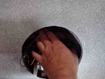
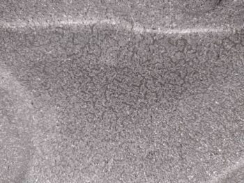
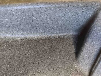
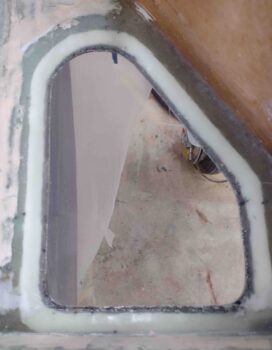
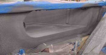
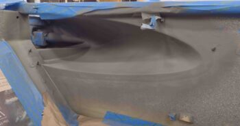
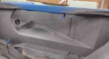
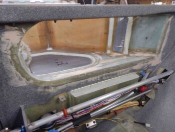
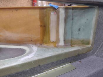
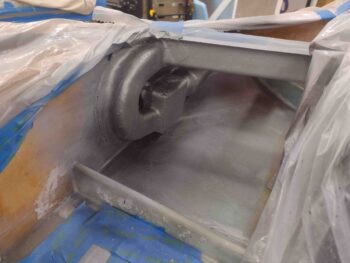
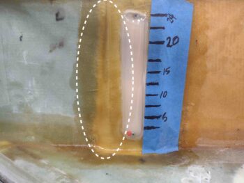
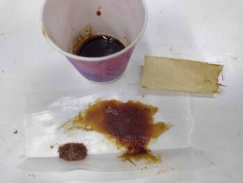
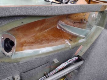
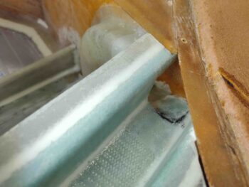
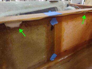
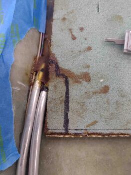
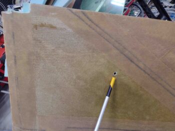
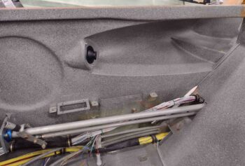
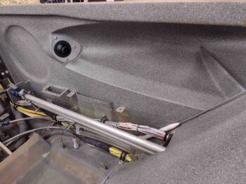
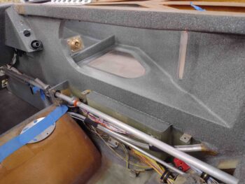
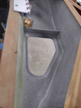
I started out this morning clear-coating the gray granite paint and quickly noticed that in a few areas the previously near-perfect looking paint surface started mottling up.  At first I noticed it in the area under the right fuel site gage (first pic).

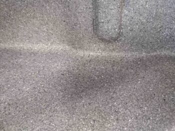
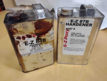
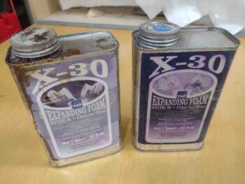
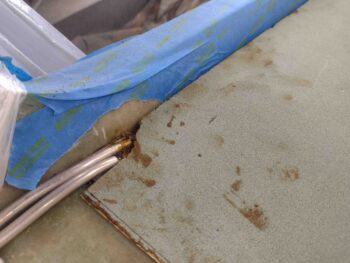
Then, when I looked around at the rest of the paint, I found another mottled area in front of the right front baggage dam.  I’m thinking it was areas of thicker paint that may not have been fully cured (although I let the paint cure overnight) and thus reacted to the clear coat. I’ll note that both the paint and the clear coat are Rustoleum.

I figured the best way to deal with the mottled paint was to “seal” it in clear coat, let the mottle reaction play out, then wait until the clear coat thoroughly cured before hitting the blotched areas with another shot of the gray granite paint… which then required another 5 hour cure cycle before final clear coat.

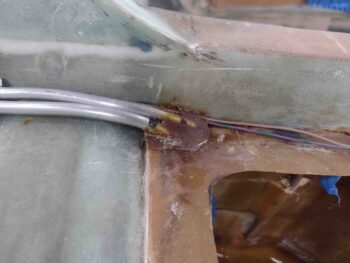
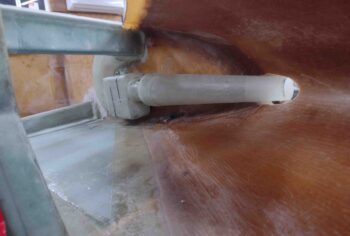
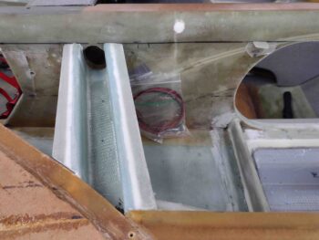
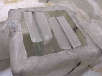
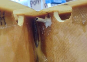
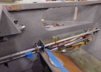
While the latest fresh coat of paint cured, I started working on notching the aft inboard right strake top core to allow it to fit around the exiting fuel vent lines.

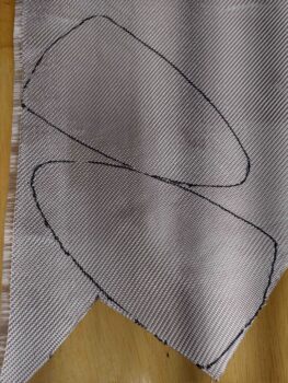
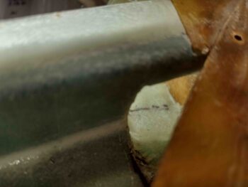
I marked up the strake top core as best possible.

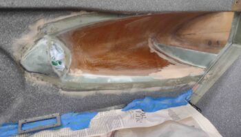
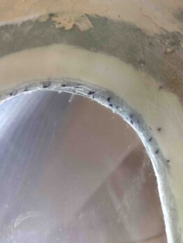
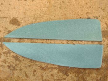
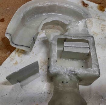
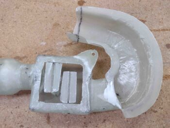
Then after a few iterations I got the notch cut and the right strake top fitted.

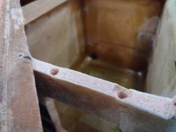
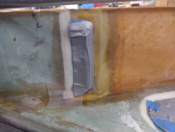
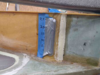
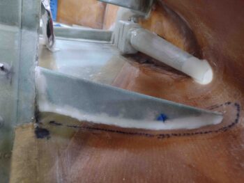
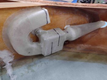
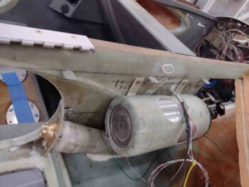
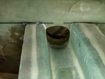
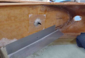
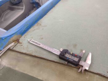
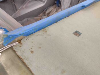
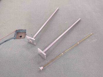
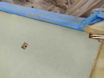
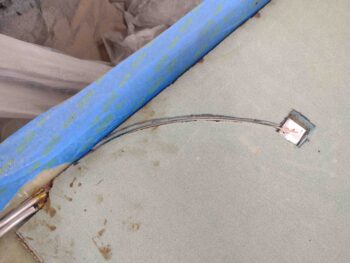
I then measured and marked the position for the fuel tank probe and after drilling it with a small diameter bit from the exterior side, I then drilled it out from the inside out.

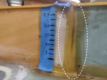
I then marked and cut out a notch for the top flange of the fuel probe.  My measurements for the fuel probe positioning is 5.5″ out from the longeron and 16.5″ from the aft edge of the CS spar forward.

This puts the fuel probe no more than 2-3″ from the fuel site gage, so I should be getting fairly close matching fuel levels on both of those (if I don’t screw anything up!).

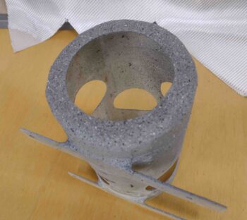
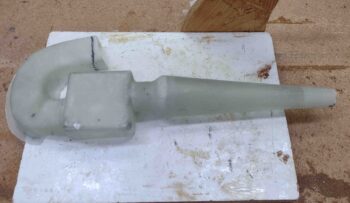
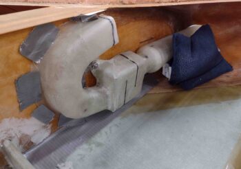
I had planned on floxing in the fuel probe body first (there’s 2 parts: the outer body/sleeve, and the inner probe), before I mount the strake top skin and then merely slide the inner electrically-connected probe into place after the strakes were closed out.

This would allow me to get the probe installed and ensure no flox got into the vent holes near top of the tube. However, the length of wire I have and then running it essentially from Point A (aft strake corner) to Point B (fuel probe) through a channel would require the wires to be long enough to not have the inner probe cant at an angle that could bend the small inner probe tube.  However, since my wires are hard set from the corner forward, if they are long enough to allow me to easily slide in the inner probe, then I would have excess wire on hand and no where to put it… a chicken vs. egg conundrum.

[Note: I thought about a long curved channel to give me more wire, in theory.  But it doesn’t really matter since I have just enough wire on the right side coming from the control box, and just a hair more on the left… so this discussion is merely explanatory)

Thus, I decided to simply —and carefully— flox in the probes after the skins are in place.

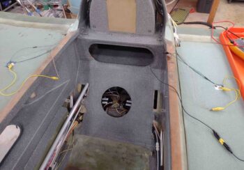
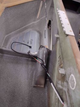
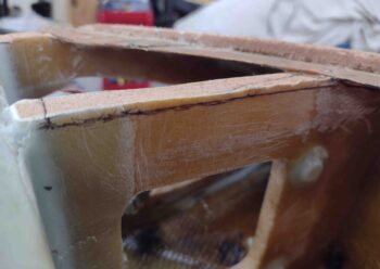
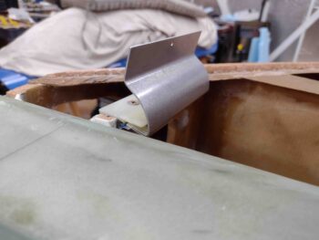
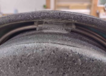
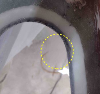
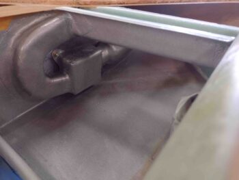
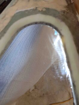
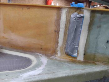
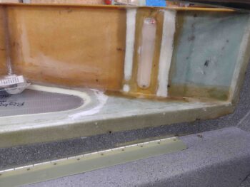
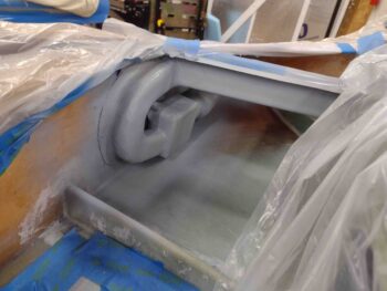
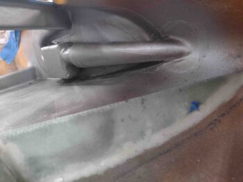
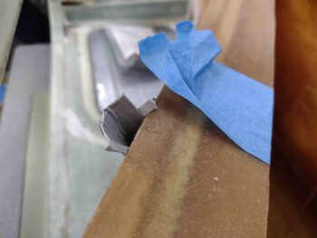
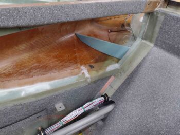
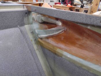
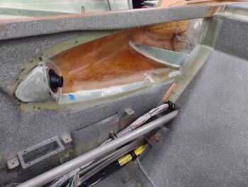
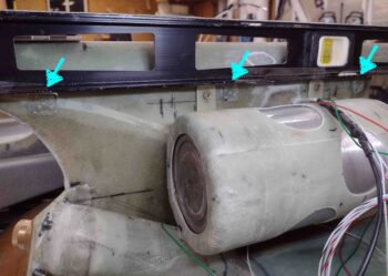
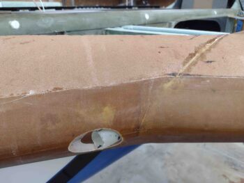
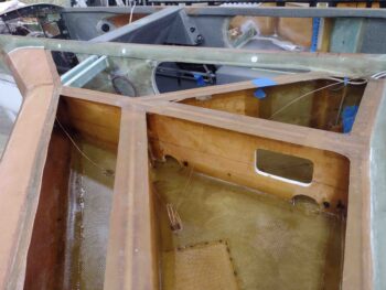
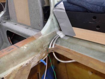
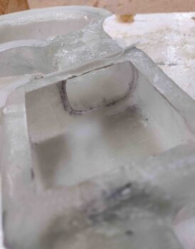
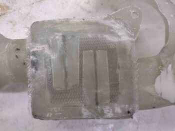
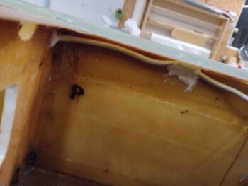
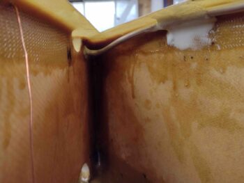
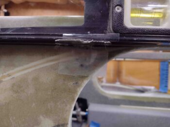
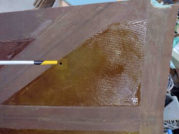
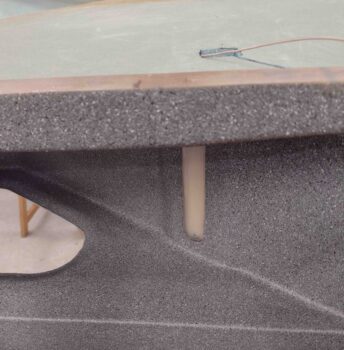
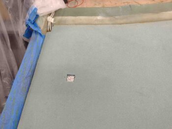
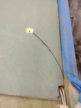
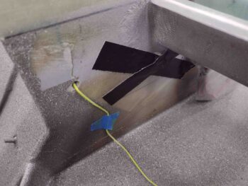
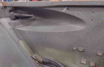
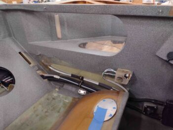
I threw a light inside the fuel tank and reset the top strake skin in place… note in the upper corner the edge of the T-hat can be seen.

I then notched the left strake top skin core in the aft inboard corner for the fuel vents, and also measured and marked out the position of the left fuel probe.

As I did on the right strake top skin, I drilled the fuel probe access hole from the inside out for a cleaner hole.

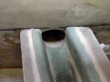
I then marked and notched the left strake top foam to allow inserting the fuel probe flange.

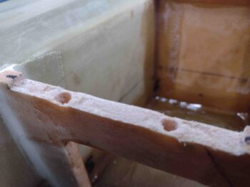
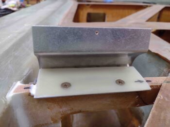
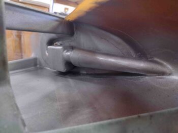
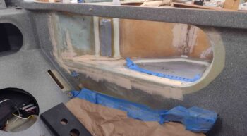
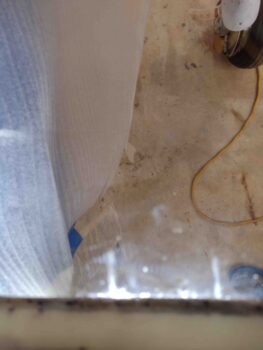
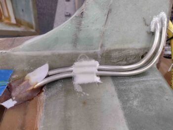
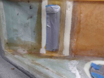
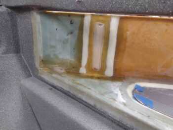
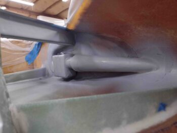
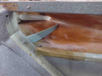
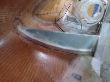
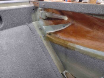
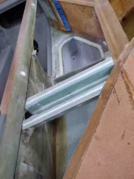
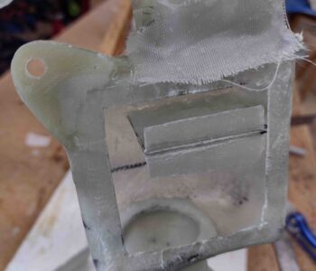
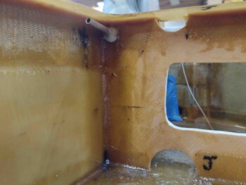
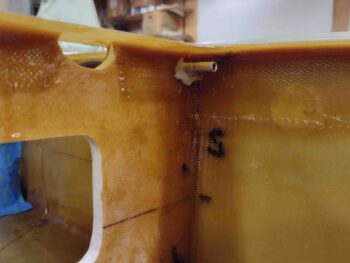
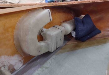
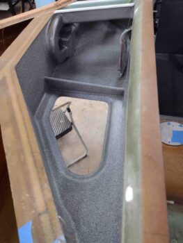
Here we have a shot from the front of the strake looking aft of the left fuel probe being test fitted into the notched strake top.

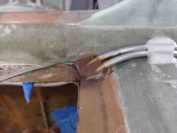
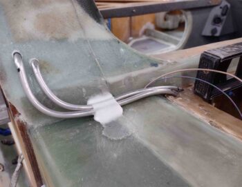
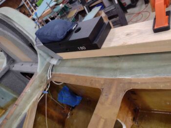
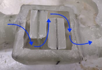
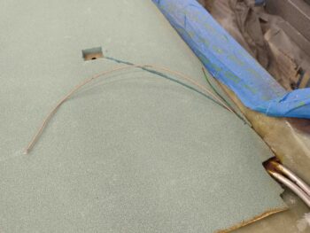
I then marked and cut a channel for the fuel probe wires (data + ground) on the right side.

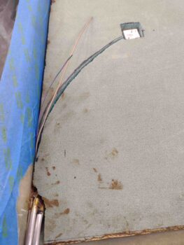
I then test ran the wires… looking good.

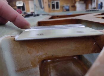
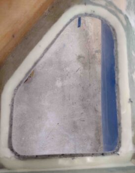
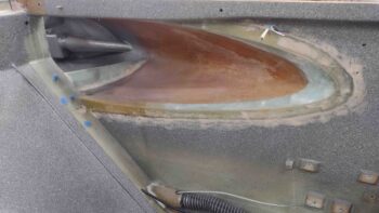
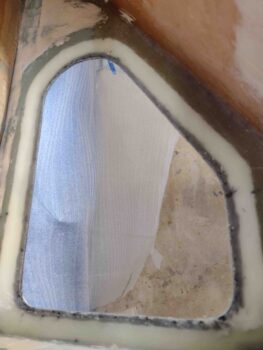
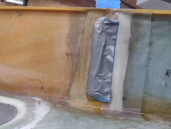
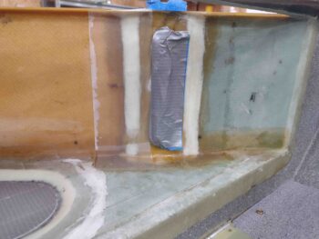
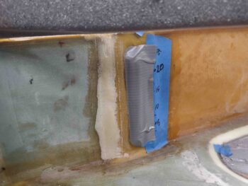
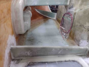
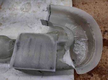
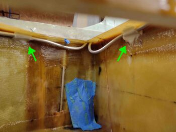
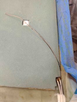
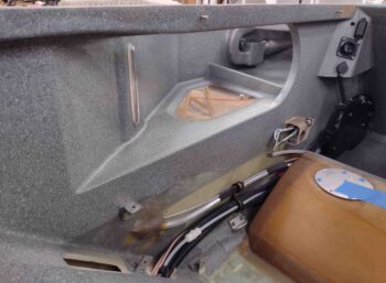
Here I again have a light inside the left fuel tank to backlight the fuel probe notch.  I’ll note that the right side fuel probe was about as close as I wanted to comfortably get to the T-hat, so I used 5.5″ x 16″ on the left side.  Moving the probe about 5/8″ farther from the T-hat than on the right side.

As I also did on the right, I assessed the wire path and marked the wire channel run.

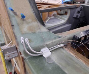
I then cut the channel for the left fuel probe wires.

And test ran those wires.  Again, so far so good.

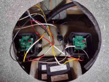
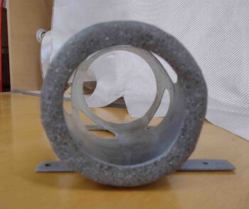
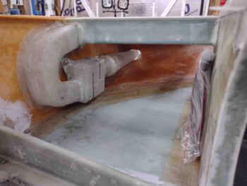
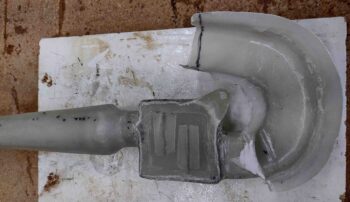
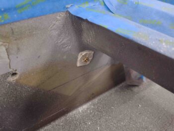
I then focused on installing yet another tidbit while I still have unfettered access into the strake baggage areas: a small #6 RivNut hardpoint that will allow me to secure the O2 system’s oxygen tube Y-splitter.  This splitter allows for one feed tube off the regulator on the Obottle in the right strake to then run through about a 30″ line to the left strake where it splits to feed both pilot and GIB cannulas.

[Side note: I called Mountain High to order a longer feed tube to facilitate my configuration above and they simply sent me a 36″ length of tubing free of charge… great customer service!]


I had planned on using a #6 nutplate/phenolic assembly mounted on a 3/8″ thick base of foam, not realizing I had any #6 RivNuts on hand.  Moreover, I can’t find my bag of small rivets and in looking for it found the RivNuts… one problem solved, but I’ll of course need to find my bag of rivets (which I know I have since I used them on the GIB eyeball vent mounting flange!).

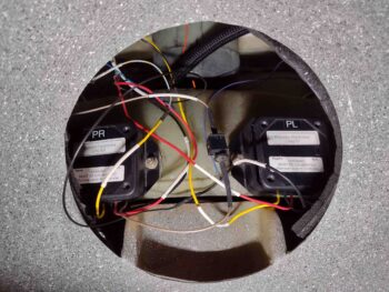
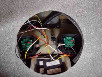
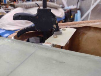
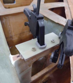
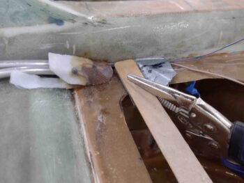
Here I have the Y-splitter test-mounted to the #6 RivNut.

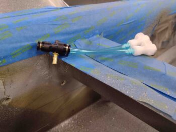
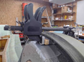
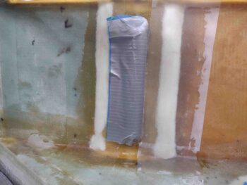
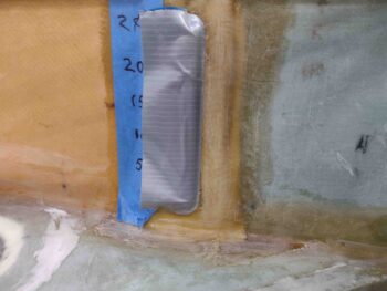
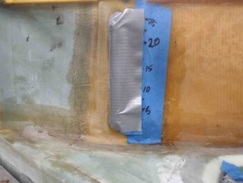
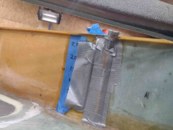
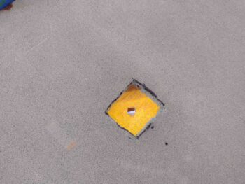
I then floxed in the #6 RivNut . . .

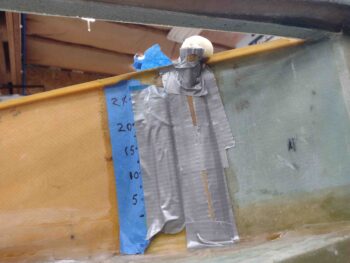
and secured it in place to cure with Gorilla duct tape.

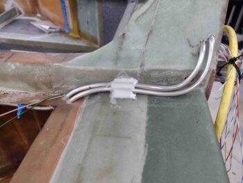
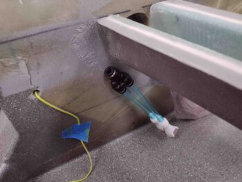
I also ran a yellow pull string to allow for pulling the O2 feed tubing from the right baggage compartment to the left.

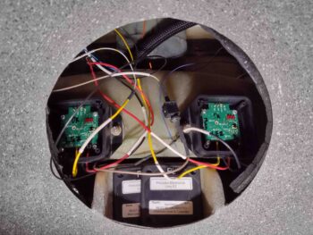
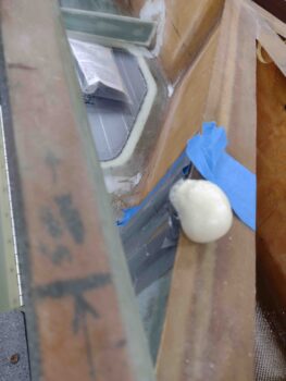
A few hours later I pulled off the tape and tape-covered-washer and then test-mounted the Y-splitter… works a treat!

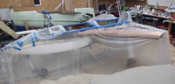
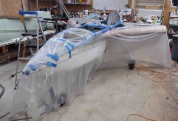
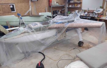
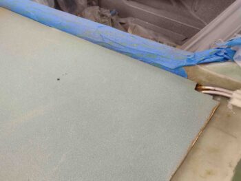
With my clear coat well into the cured state, I then spent a good hour removing all the plastic sheeting and tape to reveal the new FINISHED cockpit and strake baggage compartment paint job.  With the mottled paint issue remedied, I have to say I’m very pleased with the outcome.

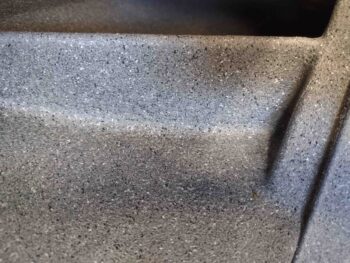
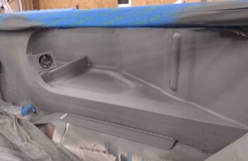
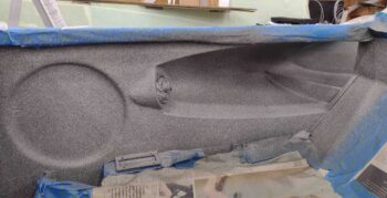
Here we have the front right side.

And another angle… with the pilot eyeball vent reinstalled.

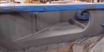
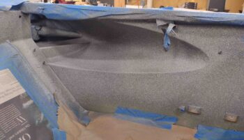
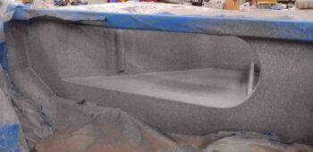
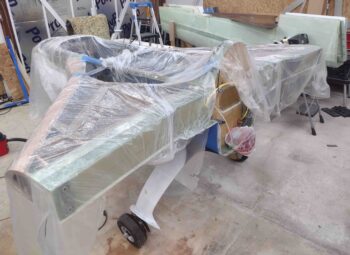
Then the left side front… note the slightly different metallic color of the RAM air scoop setup.

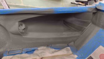
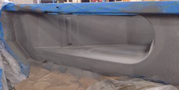
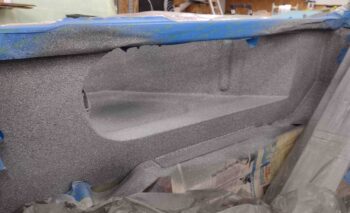
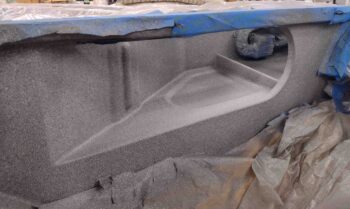
And here we have the right backseat area.  As you can see I removed the tape from both the GIB windows and the fuel site gage bubbles.

And the left side GIB area.

Finally, the baggage compartments with the GIB windows.

It was a fairly long build day and now very late in the evening (ahem, morning)… time to knock off for a few hours!

Chapter 21 – Baggage areas painted

I started off this morning by removing the clamps and the spacers to reveal my flox and glass gatekeeper to keep the fuel vents wrangled in the Turtledeck.  While the glass and flox certainly did the job, it’s interesting to note that the pressure I put on the layup squeezed a good bit of epoxy out of the glass layup and made it fairly dry.

I also grabbed shots of the E-Z Poxy floxed fuel vent lines exiting the aft corners of the fuel tanks via the flange.  I peel plied them since there will be more added to these flox bits when the strake tops get floxed into place.

I then gathered up some 600, 1200 and 1500 grit sandpaper and wet sanded the scratch on the aft end of the left GIB strake window.  If you focus on the electrical cord on the ground you can see how it disappears into a haze… that haze is the wet-sanded scratch.

I then buffed out both the right and the left GIB strake windows… and with the windows pretty much scratch free on the inside, it was time to tape them up for paint.

I also taped up a whole bunch of other things as well in prep for paint.

And covered a bunch of areas with plastic to ensure anything that was not supposed to get paint, didn’t.

I then broke out the primer and hit the pilot right baggage opening.

As well as the GIB right baggage opening…

then the left side in the back.

And finally, the left pilot baggage opening.  I have to say, I really like this gray… too bad it doesn’t cover as well as the gray granite paint.

After a good 30 minutes plus, I then painted the inside of the baggage areas and fuselage with the Rustoleum gray granite paint.

I was a bit concerned with how well it would blend with the previous paint, but thankfully it looked like it came out of the same can!  As I always say: better to be lucky than good. Ha!

And the last couple of shots.  All these pics were taken after I shot the second and final coat of paint.

I’m extremely pleased with how the paint looks.  Moreover, I’m glad I took the time to micro up the various spots of the baggage areas to smooth out the rough stuff.

Tomorrow I’ll shoot a couple rounds of clear coat before moving on to the outboard strake storage compartments and preinstall on the fuel probes.

Chapter 21 – Baggage area paint prep

Today I got up fairly early and hit the aft edge of O2 bottle mounting sleeve with a couple rounds of matte clear coat.  I know this picture isn’t that great for the paint, but the structure in the background is a pretty good shot… so I left it in the lineup.

I wanted satin clear for the oil heat RAM scoop components, so I departed for Lowe’s and got there just shortly after they opened.  I then returned and hit the RAM air scoop, vapor box and ducts with 2-3 shots of satin clear coat.

I then got to work on the inside fuselage and baggage areas for final sanding and hole filling, etc. in prep for final paint.  In my mind there is a bit of a priority in how nice you make these areas in order of visibility eh? <wink>  With the front right pilot baggage area getting the most love since it’s the most visible when the plane is opened up.  #2 would be the back seat right baggage area.  #3 would be the front seat left side, with the back seat left side being #4.

Here we have the front seat pilot strake/baggage openings.  I sanded a good bit inside, as well as the new baggage dams, and quite a bit around the perimeter where the glass overlaps into the main cabin onto the fuselage sidewalls.  As you can see, after some rigorous sanding I then hit these areas with a bit of micro/West 410 mix.

I then moved aft to the back right side.  Again, the main culprit is the overlapping glass into the cabin on the sidewalls.  After a fair bit more sanding I employed micro/West 410 again to help smooth things out.

As I did on the back left side.  I have to say, this was quite the workout leaning into the cockpit and sanding all this stuff.

I also whipped up some flox and a couple of plies of prepregged BID, about 3/4″ x 1″, and first floxed up the fuel vent tubes in the center top area of Turtledeck.  I then used a taped up rectangular foam wedge (with the 2-plies of BID and a top layer of peel ply) followed by a taped up 1/2″ thick wood piece to force the fuel vents as far aft into the groove between the GIB headrest and the outer Turtledeck frame.

Hopefully this will keep those fuel vent lines wrangled inside of there until I can figure out exactly what I want to do with all that.

I then whipped up some flox using E-Z Poxy 84B hardener for the right side aft internal corner for the fuel vents exiting out of the top fuel tank flange (again, sorry, no pic).

I then pulled down the Scratch Off plexiglass cleaner and scratch removal kit.  I cleaned up the pads in the house since I haven’t used this in a couple of years.

I then got ready to hit the left GIB strake window since I have some pretty decent scratches/epoxy residue from the epoxy wicking up under the tape seams (big sigh).

These are before shots of the scratches…

As is this.

There’s a chart in the Scratch Off instructions on where you should start depending on the type of scratch you have, with it noting that you can always start over with more extreme measures if need be.

Well, I was 3 pads into the sequence when I really noticed one of the big scratches I was going for wasn’t buffing out.  I had skipped Step 1 which starts with 600 grit wet sanding, and went straight to the pads…

Well, tomorrow I’ll go back to it starting with the 600 grit wet sanding.

I will note there is definitely a very noticeable improvement in the overall clearness and cleanliness of the window.  I’ll hit the outsides of these windows at a later point.

After a VERY long day in the shop, I’m calling it a night.

Chapter 21 – Fuel site gages complete

With my plies of BID —one for each side— already cut, I went ahead and sanded and micro’d the added foam before laying up the glass.  I then peel plied both sides.

While the layups on the inboard edge of the fuel site gages cured, I whipped up a batch of EZ Poxy flox using my just tested (and passed) E-Z 84B hardener.

I then applied a nice good bit to the top and inside of the aft corner flange of the left fuel tank around the exiting fuel vent lines (sorry, no pic right now of the inside flox).  I then peel plied the external flox since it will get more stuff added to it when the strake tops are closed out.

Note that I also used the last little bit of micro in the cup from the fuel site gage layups to seal/secure the fuel vent lines going into the turtledeck.

I then did the same thing to the aft corner of the right fuel tank, except with the stir stick being held in place that in turn is holding the fuel tank probe wires in place, I didn’t have access to slather up the underside of the fuel vent lines exiting through the flange.  I’ll get that in the next day or so.

I then took a hard look at the required angles and possible configurations for the outboard strake storage compartments.  I jotted down some ideas before turning back to the task at hand: cleaning up the fuel site gages edges.

Once again, I used MGS 335 with fast hardener, so after a little over an hour the layups were cured to the point of being dry to the touch.  I pulled the protective tape off the site glass bubble on each side and reversed it to focus on the outboard/forward side of each site gage.

I then thoroughly sanded and cleaned the the outboard/forward edge of each site gage.

I then built a couple more taped cardboard forms and poured in some foam.  I got greedy and tried to do both from the same cup of pour foam, which resulted in only the top half of the right side getting foam.  I had to cut another hole half way down, reset my funnel in place and do another pour.  Sorry… no pics.

I then sanded down the set foam on the outboard/forward side of each site gage.

And then as I did on the inboard/aft sides, I micro’d the foam and laid up a prepregged ply of BID on each side.  I then peel plied the layups.

A few hours later I pulled the peel ply and Voila!  The fuel site gages are looking WAY better and much less lopsided top-to-bottom on the edges than they did before.  Although not perfect, this is significantly better than what I had before!

With yet another significant prerequisite task completed, I wasn’t in the mood to start on another in-depth task this evening.  So I decided to knock out some painting.

First up, I shot some primer before some interior gray granite paint on the very aft ring of the O2 bottle mounting sleeve.  This is pretty much all that will be visible when it’s installed in the strake baggage compartment.

I then spent a good little bit of time covering up the fuselage, strakes, sides, etc. with some protective plastic for a specific part I wanted to paint that will not be the standard gray granite interior paint scheme.

I decided to spice things up just a bit and have some fun by highlighting the RAM air scoop/vapor box/ducts by painting them a metallic silver.  First up I hit the components with some primer.

Before shooting some medium dark metallic silver paint onto the RAM air scoop components.

I’ll let all the painted stuff cure overnight before clear coating them in the morning.  And with that, I called it a night.

Chapter 21 – Fuel site gage cosmetics

Today was a light build day since I enjoyed the beautiful day and spent some time with my girl in New Bern, NC.

Upon returning home I started the process of reconditioning my E-Z Poxy hardeners on hand, both the E-Z 84B and 87B, to ensure they are ready for action.  This involved boiling up some water and keeping these hardeners at a temp between 160-190° F for a couple of hours.  Occasionally I would shake the containers around and ensure they were mixed as best possible before putting them back in the hot water.

I then grabbed a couple of shots of my current fuel site gages and what I consider to be a non-negotiable cosmetic issue… one that would continuously bother me if I didn’t remedy it: since I used wet micro in glassing them during install (arguable too wet maybe), as the layups cured gravity took over and the micro naturally sagged a bit towards the bottom. It’s not horrible, but it is also clearly not uniform on the edges of the fuel site gages.

It simply needs to be fixed solely for cosmetic reasons.

I started by taping off the site gage windows to protect them as I then thoroughly sanded the inboard edge of each site gage.

I then rounded up my trusty X-30 pour foam parts.

Made some taped-up cardboard dams, this one for the right fuel site gage.

Added a little cardboard/tape funnel . . .

Whipped up some foam and poured it in.

Here we have the foam expanding out of the funnel of the mold.

And about an hour later I pulled both taped molds off the side walls to reveal what will be the edge filler to smooth out each inboard side of the fuel site gages.  I’ll of course micro and glass these after they’re shaped, and then do the same process on the outboard edges.

Jess was making dinner, so in my quest to not make her a complete “Long-EZ build widow,” I simply cut the BID pieces for these two respective site gage layups and called it good for the evening since I didn’t want to be rushed on my sanding & shaping of the added foam edges.

I did however take a few minutes to whip up some E-Z Poxy using the 84B hardener to test it out.  I used this E-Z Poxy to layup 3 plies of scrap BID, peel plying most of the layup.  I also whipped up a decent dollop of flox to test that out as well.

Now, I’ll note that I use fast MGS hardener on 80-90% of my layups, which is workably cured in about an hour… and practically cured in 3-4 hours.  So the 3-day cure time for EZ Poxy with E-Z 84B is definitely an adjustment for me . . .

And with that, I called it a night.

NOTE: I’m cheating here a bit on this blog by traveling into the future 12 hours (as I go to post this actually the next morning) to show that the E-Z 84B epoxy is looking good for having spent the night in about a 65° F shop and again, taking into account a 3-day required cure time.  The BID layup is dry, but quite flexible still.  On the flox dollop I was able to cut into it a good bit with a razor knife.  I’ll check this out in another 12-24 hours and report back on it.

I’ll further note that since I plan on being ready to paint the interior strake baggage areas and cabin in less than 3 days, I’ll be sticking with MGS epoxy for much faster cure times to ensure all epoxy is cured when I shoot the paint.

Chapter 21 – Strake front baggage dams

Although I listed out all my remaining prerequisite tasks required before closing out the strake tops, I actually focused today on a task that was NOT on that list: strake baggage front dams.

I started out spending over a half hour with my Sharpie and cardboard dialing in the shape and position I wanted for the front strake baggage dams.  I know some guys put small lips right at the strake opening, but I want to be able to rest my arms in the strakes without them going numb.  I also wanted some elbow room so I set them back just a hair.

Last night I ripped some 3/8″ thick PVC foam down to 1/4″ thick to use for these baggage dams.  Here’s the final prepped foam cores for the strake front baggage dams.

I then set the foam cores above tightly together and added about an inch to make up a paper pattern to use to mark my BID for cutting.  Each dam gets 1 ply of BID.

I used thick micro with about 5 thick dabs of 5-minute glue to set the front baggage dams in place.  I then added a micro fillet to each side of each baggage dam before laying up a ply of BID on each one.

I also snagged the unused prepregged 2-ply BID I set up for the Vapor Box Clickbond and laid it up around the nose of the RAM air scoop exiting the strake leading edge.

I then peel plied all the layups.

A few hours later I pulled the peel ply and cleaned up the layups.

Here are a couple more shots of the front baggage dams from wider angles.

Finally, here we have the left strake baggage dam from the aft side.

With this task out of the way, tomorrow I’ll press forward to knock out more strake closeout prerequisite tasks.

Chapter 21/22 – RAM air scoop done!

I started out today checking over my just-floxed-in-place duct/vapor box/RAM air scoop. All looked good so I proceeded to add a dollop of micro at the widest point of the RAM air scoop on top and then laid up a 1″ wide ply of BID —essentially a strap— to secure the RAM air scoop to the BL23 rib.  I then peel plied the layup.

I also checked out my other dollop of micro with a ply of scrap UNI over it to hold the right fuel vent lines in place in the corner of the longeron and CS spar.  I laid this up last night to cure overnight.

Remember, this area will all get covered with the upper cowling sloping shoulders.

This AM I had a bit of micro left over in the cup from my RAM air scoop securing layup, so I pushed it in and around each of the vent lines going into the turtledeck.

Last night I had just a smidgen of flox left in the cup so I quickly drilled holes into 3 of the 90° 3-ply brackets and floxed them up under the taped level, that was of course sitting on the cross line of where the underside edge of the strake top will sit.

This morning I removed the tape securing the tabs to the underside of the level and then removed the level… Voila! Tabs to hold up the inside edge of the right strake top during install.

I then got busy with what turned out to be quite the layup.  Also a significant feat in that this puts to bed a 6-YEAR project on this oil heat system Scoop & ductwork!

My final piece of the puzzle was to micro, install, glass and peel ply the RAM air scoop cross duct/bridge into place.

Here’s a shot of the glassed duct/bridge in place.

And yet another shot from above.  I’m really happy with how the intersection with the BL23 T-hat and strake leading edge flange came out.

I still need to do some work on trimming the nose of the RAM air scoop and shaping the leading edge around it.

I blended the duct/bridge in with the original oil heat duct entrance through-hole on the side of the fuselage, just aft of the upper pilot’s seat.

Here’s another shot from the aft side.  Again, I’m extremely pleased with how this came out.

A couple more closer-in shots of the micro and BID transition from the duct/bridge into the fuselage oil heat duct hole.

On the the other BL23 side is the where the half-circle duct terminates into the cross duct/bridge.  It won’t win any beauty prizes, but its solid, smooth and seemingly air tight!

I grabbed this shot to show how the duct/bridge ties into the rest of the left strake structure.

I then weighed down, micro’d, glassed and peel plied the left fuel vent lines in the corner of the longeron & CS spar like I did on the right side.

Here’s a closer shot of that deal . . .

And a few hours later when I took all the weight off and pulled the peel ply.

I’d like to refer to a couple of different lists now (yes, I’m a lists guy!) …

The first list is from a post I made in late June 2017 when I was working on the oil heat air ducts.  It is a list of the remaining phases of the oil heat system.  I went ahead and updated that list here using colors to denote what’s been completed and what I still have to do (i.e. valve manipulation):

  • Phase II – Heat exchanger glassing
  • Phase III – Ductwork interface holes drilled and valves built
  • Phase IV – Ductwork installed with heat exchanger and valves in place
  • Phase V – Oil pump installed & oil lines run
  • Phase VI – Pilot seat area ductwork constructed and installed
  • Phase VII – Instrument panel forward ductwork constructed and installed
  • Phase VIII – Valve cables terminated and handles installed

The next is the strake closeout prerequisites list that I posted within the last couple weeks … let’s check that one as well to see how I’m progressing:

First, the following tasks that were completed:
O2 bottle mounting in composite sleeve
Installing main fuel tanks drain screens
⇒ Installing/glassing GIB strake/baggage compartment windows
⇒ Installing/glassing right strake GIB NACA vent duct and eyeball vent
⇒ Installing/glassing GIB strake/baggage compartment cross support mini-bulkheads
Installing/terminating main fuel tanks vent lines
Constructing/glassing/installing left strake RAM air scoop/ducts for oil heat system

That leaves these tasks to be done:
⇒ 
Outboard storage compartments on the top strake side initial tasks
Cleaning up fuel site gages edges (cosmetic)
Prepping/priming/painting strake baggage and final cockpit areas
Wiring and install prep main fuel tanks fuel probes

Wiring fuel site gages LED lights
Installing/glassing/wiring GIB map light
Designing/constructing/installing left/right fuel site gages video camera mounts
Wiring/installing fuel site gages video cameras

Note how many tasks on the to-do list are wiring.  I’ll further note that I won’t complete these tasks until after the inside of the baggage compartment area is painted… simply because I don’t want a web of wires in my way as I paint.  Nor do I want to paint all my wires that I have nicely color coded and labeled!

Chapter 21/22 – RAM air duct floxed in

I started out today adding micro & flox to the base of the Vapor Box Clickbond before laying up a ply of BID to secure it.  I had originally planned on 2-3 plies of BID, but the air duct will cross over this glass and I didn’t want to add to the gaps or cause any sealing issue.

Furthermore, I peel plied it thinking I would simply add another ply or two as the duct was getting set in place, but that didn’t work out either…. more on that later.

I then pulled the peel ply on the 3 sided (top, bottom, inboard) layup securing the duct to the aft side of the vapor box.  I then cleaned up the layups.

I also Dremeled the corners and sanded the edges of the vapor box aft internal duct opening.

I added a small bead of flox and then laid up the last ply of BID on the outboard side (facing up below) to finish the duct-to-vapor box attachment.

I then got to work installing the vapor box airflow tabs, securing them in place with small beads of flox.

Here we have the aft, lower airflow tab floxed in place inside the vapor box.

I then installed the forward/upper tab using the same method.  I added arrows to the pic below to show how the air will move through the vapor box, with the airflow tabs pulling most of the moisture out of the air.

And finally, a couple more final shots with both airflow tabs floxed in place inside the vapor box.

I then laid up 2 plies of BID on the outboard side of the vapor box to close it up and seal it for air movement.  Here you can see where those “T-hats” on the airflow tabs really helped in supporting the final layup to seal up the vapor box.

I then peel plied the vapor box’s 2-ply BID closeout layup.

While the vapor box cured, I then got to work on securing my not-so-sexy fuel vent tubes inside the respective fuel tanks.  Here we have spots of micro and a ply of BID in 2 separate spots to secure the right tank’s forward fuel vent line.

And the same thing in one spot for the right tank aft fuel vent line.  I also added a dollop of flox on each fuel vent tube poking through the BL23 rib, both on the front vent and aft… also with a dollop of flox on each side of the BL23 rib.

Here we have the left fuel tank with some micro and BID securing the front and aft fuel vent lines.


As I did on the right tank, here’s the forward left tank fuel vent line with some flox keeping it nice and secure.

And a shot of the forward fuel vent line splotch of micro and BID ply, with dollops of flox on each side of the BL23 rib to secure the aft fuel vent line.  Yeah, working from above trying to get your head down into the tank pockets low enough to see what’s going on leads to some more not so awesome looking glasswork… but they work and the fuel vent lines aren’t going anywhere.

A few hours later I pulled the peel ply and razor trimmed around the perimeter of the 2-ply BID layup on the outboard side of the vapor box.

I then whipped up some flox to finally get this whole RAM air scoop, vapor box and duct assembly mounted into the left strake baggage compartment.  I applied a bead of flox to the flanges on the duct and then mounted the vapor box mounting (and alignment I should say) tab to the Clickbond.

As for the Clickbond, I didn’t add any more plies mainly because the face of the Clickbond had too much flox and glass on it and was keeping the duct flanges off the BL23 sidewall just a hair… so I had to do some judicious sanding on both the Clickbond face and the vapor box mounting tab. Which did the trick. But no more plies of glass for this bad boy…

With a bit of flox leftover, I went ahead and mounted one of the 90° angle 3-ply tabs on the side of the fuselage.  I then added a ply of BID over the tab with some peel ply.

About an hour later (I used fast hardener) I pulled off the tape that was securing the duct to the BL23 inboard sidewall.

I then left the floxed duct to cure overnight. I have to say, so far I’m really digging what I’m seeing on this RAM air scoop setup.