Workshop – External Lights

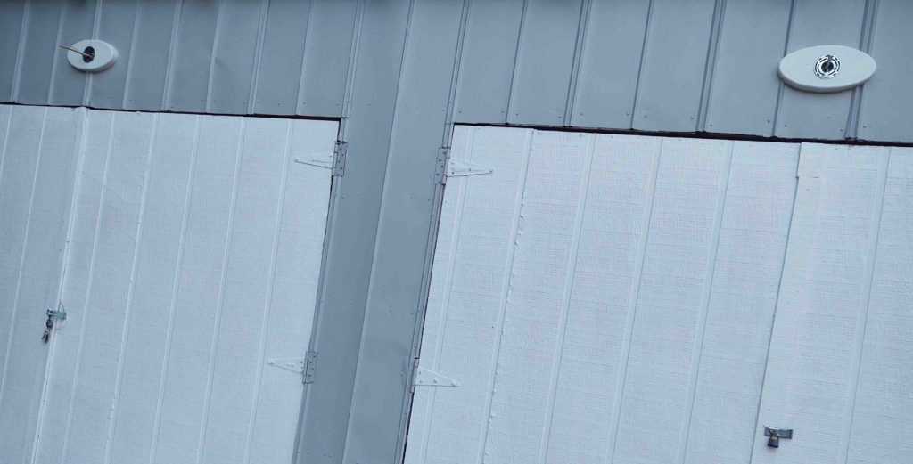
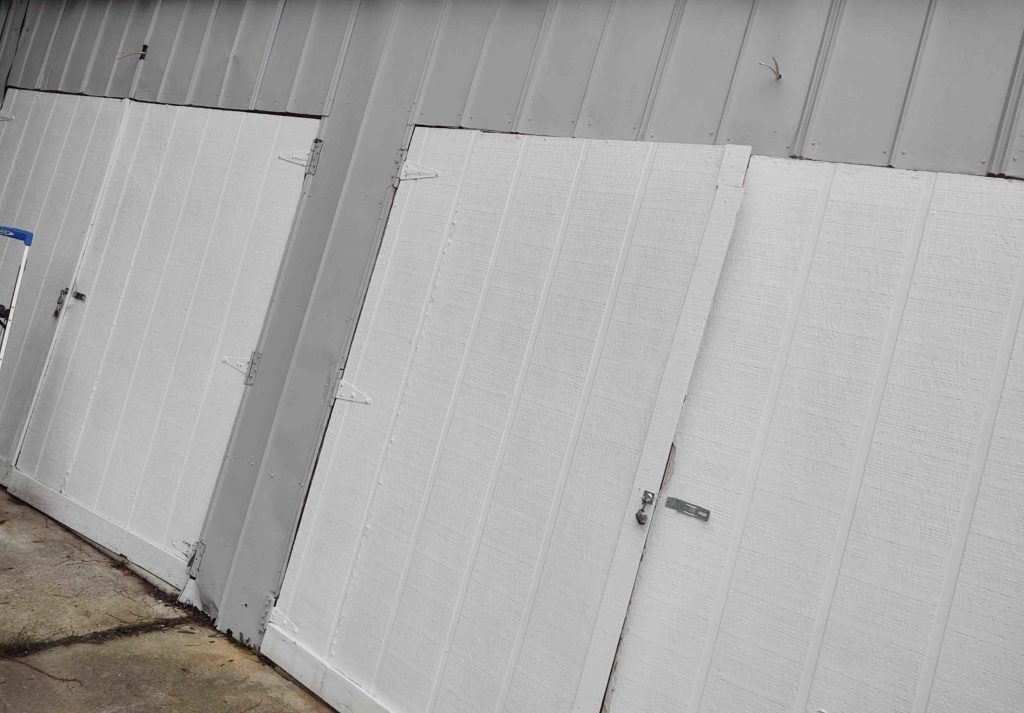
Part of the process of finishing up the insulation and paneling over the last set of big doors was wiring up some over-door lights, one over each set of big doors.

I do a LOT of work outside in front of the shop, whether cutting wood, grinding metal, welding, etc. and often I simply do not have enough light –or run out of light– without having external lights at the middle and far end of the shop (basically the big door areas).

I actually ran the electrical wiring months ago, but finally finished this up tonight.

As for the lights themselves, I wanted a way to cover up the junction boxes that the light bases are secured to. So I decided to cut some ovals from a scrap 2×10, with cutouts in the middle to hide the junction boxes embedded in each oval’s center.

Over the last couple of days, I painted a couple of coats of white paint on the decorative oval discs before mounting them around the J-boxes.

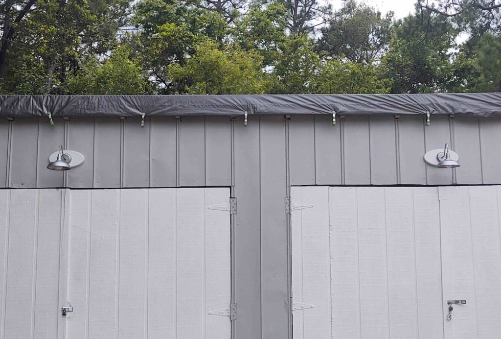
After getting the oval bases mounted and caulked with a final coat of paint, I then mounted the lights.

As an aside, the simple truth is that the original builder of my workshop didn’t build enough pitch into it, so with the rain being so intense as it’s been over the last few weeks it has overwhelmed the grommeted screw fasteners to the point that my ceiling insulation was, over time, soaking up water. I decided that I would have to treat literally each screw with added water-proofing, but in the mean time I simply covered a big section of the roof with a 9 mil thick tarp to keep this onslaught of rain at bay. Since the tarp went up it has eliminated any damp/wet shop ceiling insulation.

With the “tarp story” explained, here is some more pics of the new exterior over-door workshop lights.

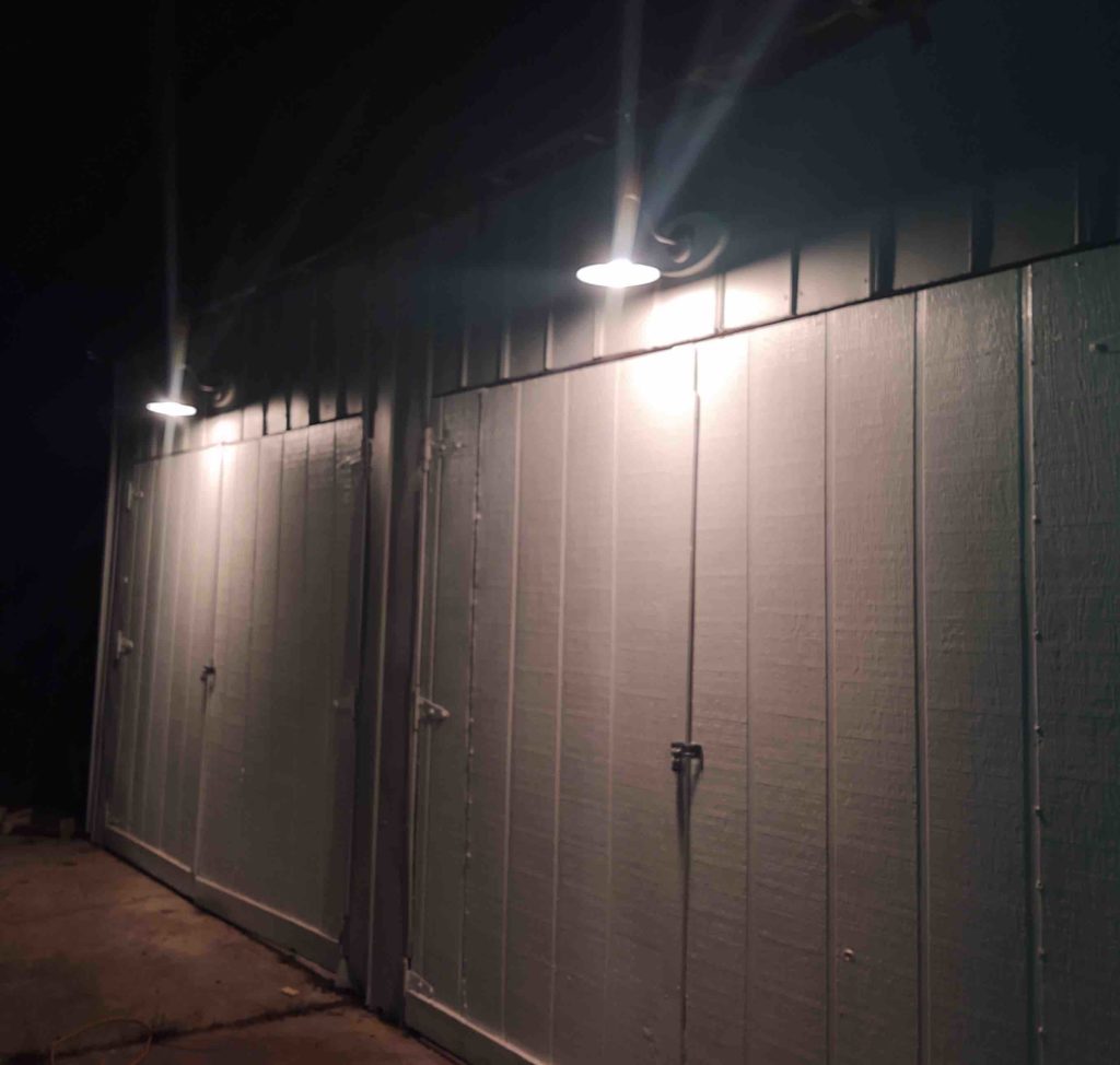
Finally, here is a shot showing the lights in action. I can tell you that these lights will be a huge benefit in providing added visibility –and thus added capability– during a myriad of work tasks.

Again, I’m pressing forward to finish up the shop to get back on the plane, and I’m getting pretty darn close . . .

Workshop – 9th Wall Section Completed

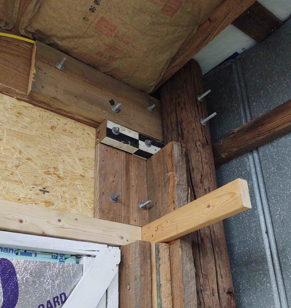
Over the last couple of days, with good weather in hand, I was able to reframe the upper front corner of the shop from damage it had apparently incurred during Hurricane Florence.

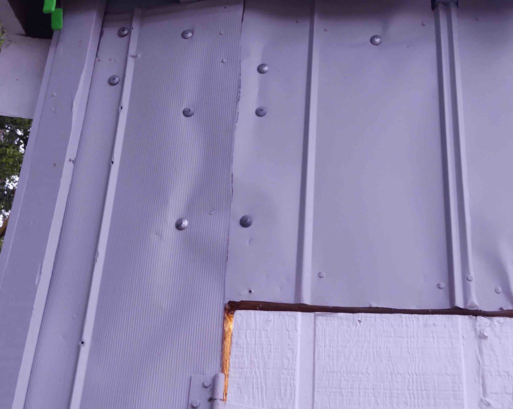
The end portion of the main beam along the top front of the shop had been cracked and needed some TLC. I cut out the cracked portion, spliced in a new custom fit 2×10 piece, then covered that with even another segment of 2×10 to give the beam repair some surface area to bolt to both the existing beam and the corner support pole.

As you can see, there is quite a hodgepodge of 1/2″ galvanized bolts protruding into the upper corner to secure and buttress everything together.

The result of all the lag bolts on the outside corner made it look as if I had taken a shotgun to the workshop. It may not look fancy, but it definitely worked in making the corner secure.

As I worked to secure the end of the front roof support crossbeam, I also filled in the upper portion of the front wall above the big doors (that I reported finished in my last post) with insulation and then covered with OSB.

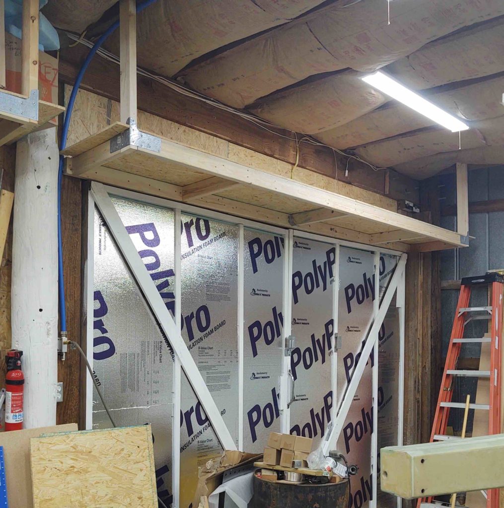
The last major step completed tonight was that of finishing the hanging shelf over the last set of big doors, pretty much as I had done for the middle set of big doors. This completes the front wall of the workshop, leaving only the front side wall (a bit of it shown on the right side below) to be insulated and covered.

Again, the last two (2) major tasks to be completed before I call the shop open for business regarding airplane construction is 1) the remaining wall segment insulated and covered, and 2) the milling machine installed and operational.

Workshop – A big step closer

Today I worked the entire day on insulating the last set of big doors.

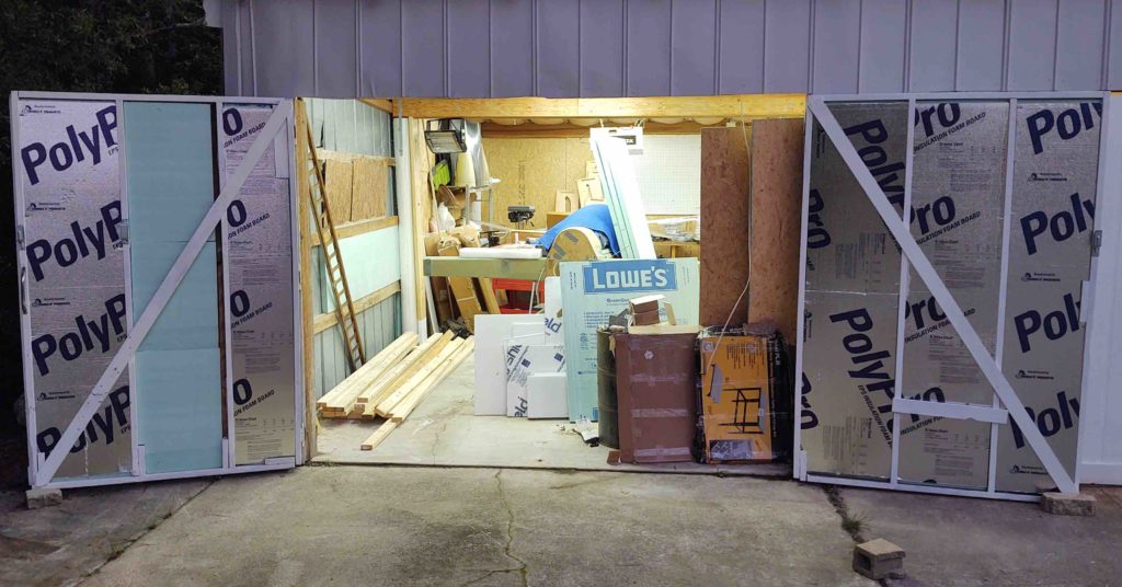
I took this shot below to show that the first layer of insulation to go in is the 2″ thick blue-green foam, then a final top 1″ layer of white foam with a shiny aluminum foil-like surface.

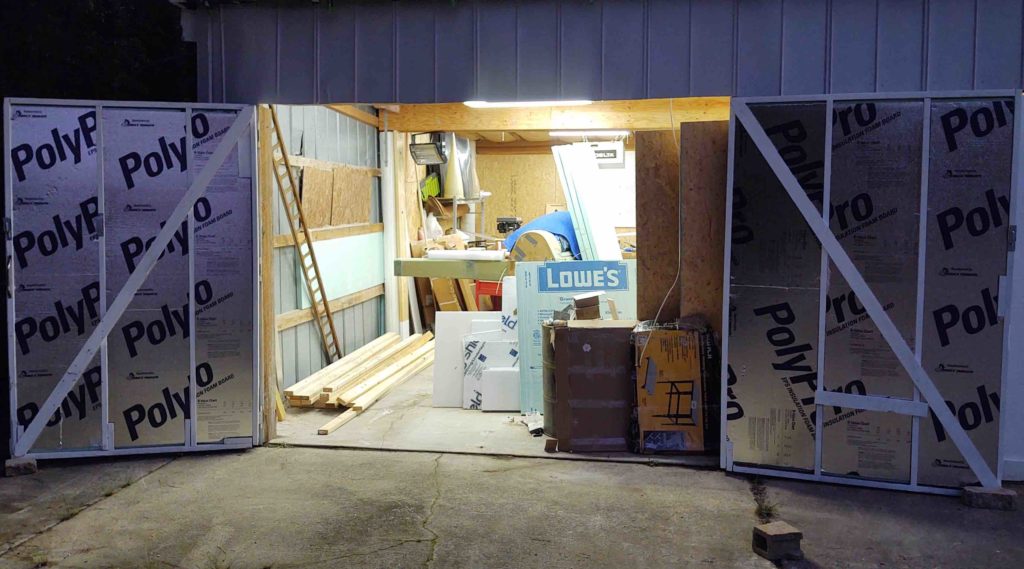
Below is the final shot of the last set of big doors insulated.

I took this pic at more of an angle than above so you can see a bit more of the final wall segment –to the left– that needs to be completed. The foam panels for that wall are leaning up against the fuselage.

There is a another strip that needs to insulated, that I’ve already started, and that’s about 2/3rds of the cross strip immediately above these big doors from opening to ceiling.

Pressing forward.

Tooling Up – Lathed Mill Socket

Today I started out by flipping the engine back upright, reinstalling the desiccant plugs and tying in the desiccant dry air lines to be pumped into the engine. I had flipped the engine upside down last week to let the camshaft soak in oil for a few days.

I then set about to finish creating a unique socket for my Mill’s power draw bar, to allow for quick change outs of the milling machine tools. As I mentioned previously, the mill’s power draw bar uses a 12mm square nut that I mistakenly thought I could use a 12mm 12-point socket on to drive with a 3/8″-drive impact wrench.

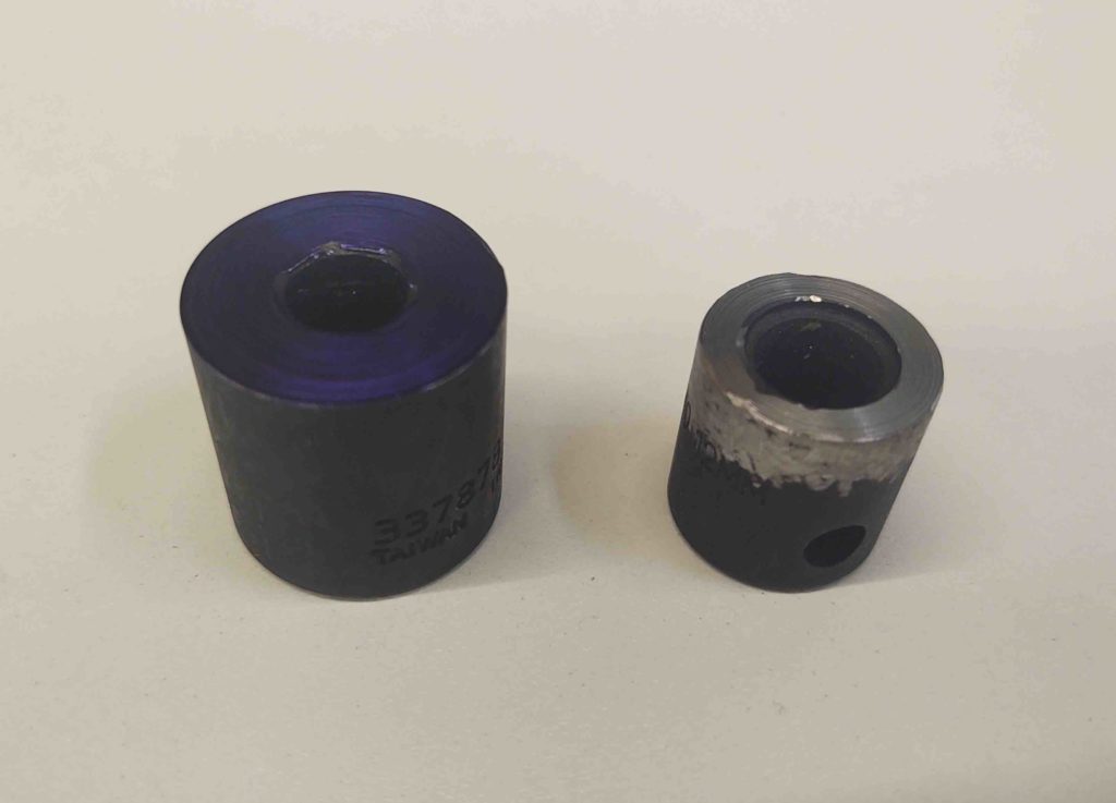
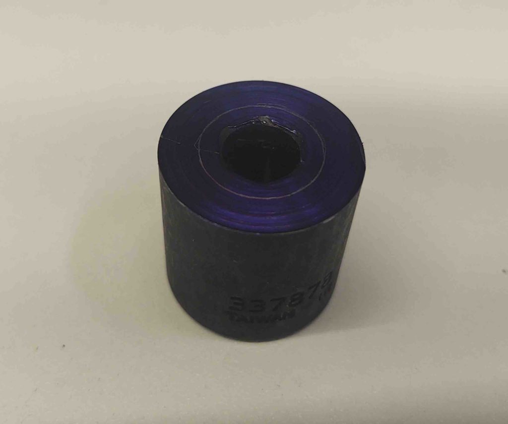
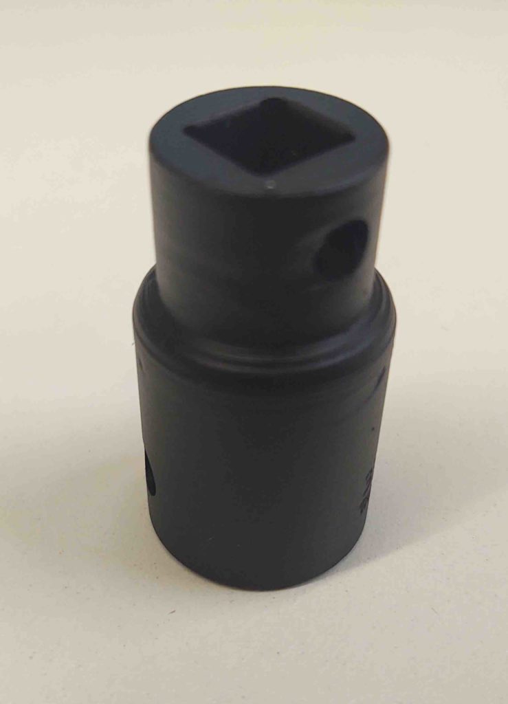
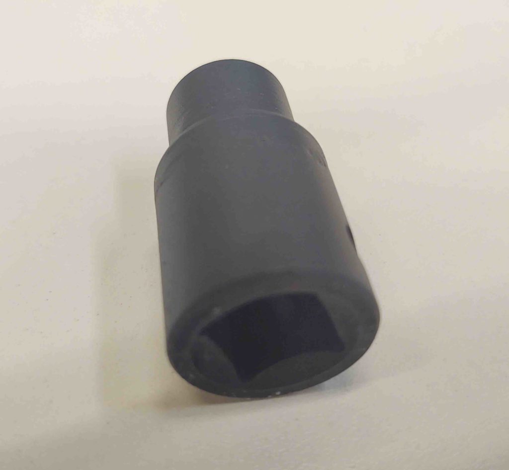
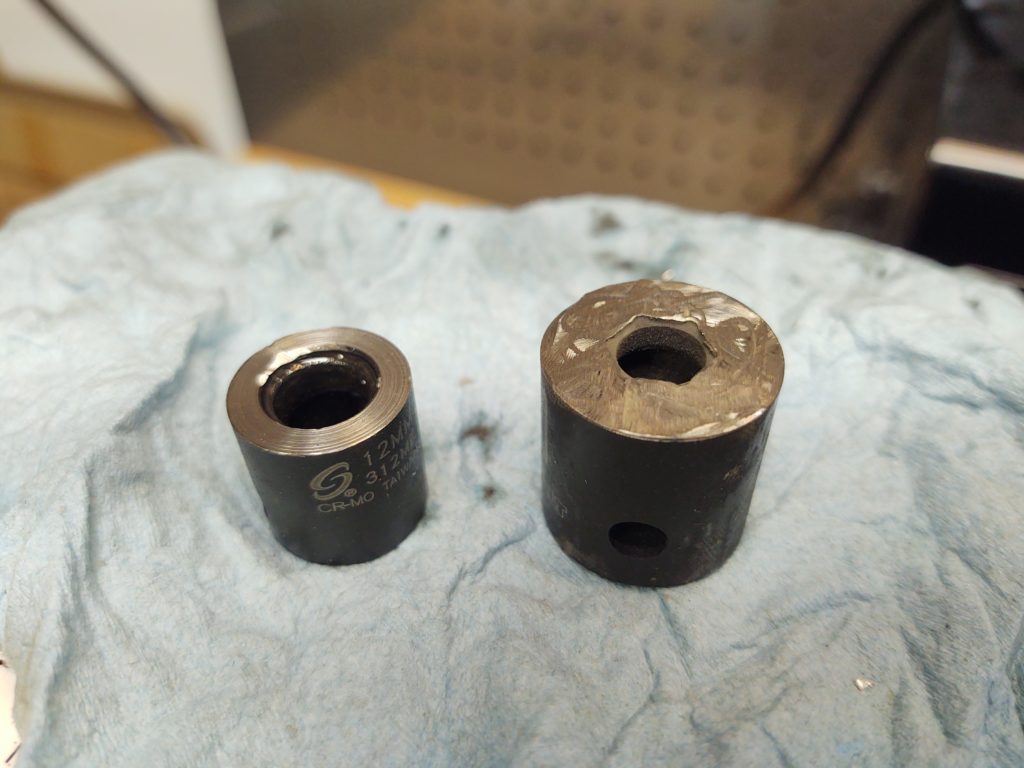
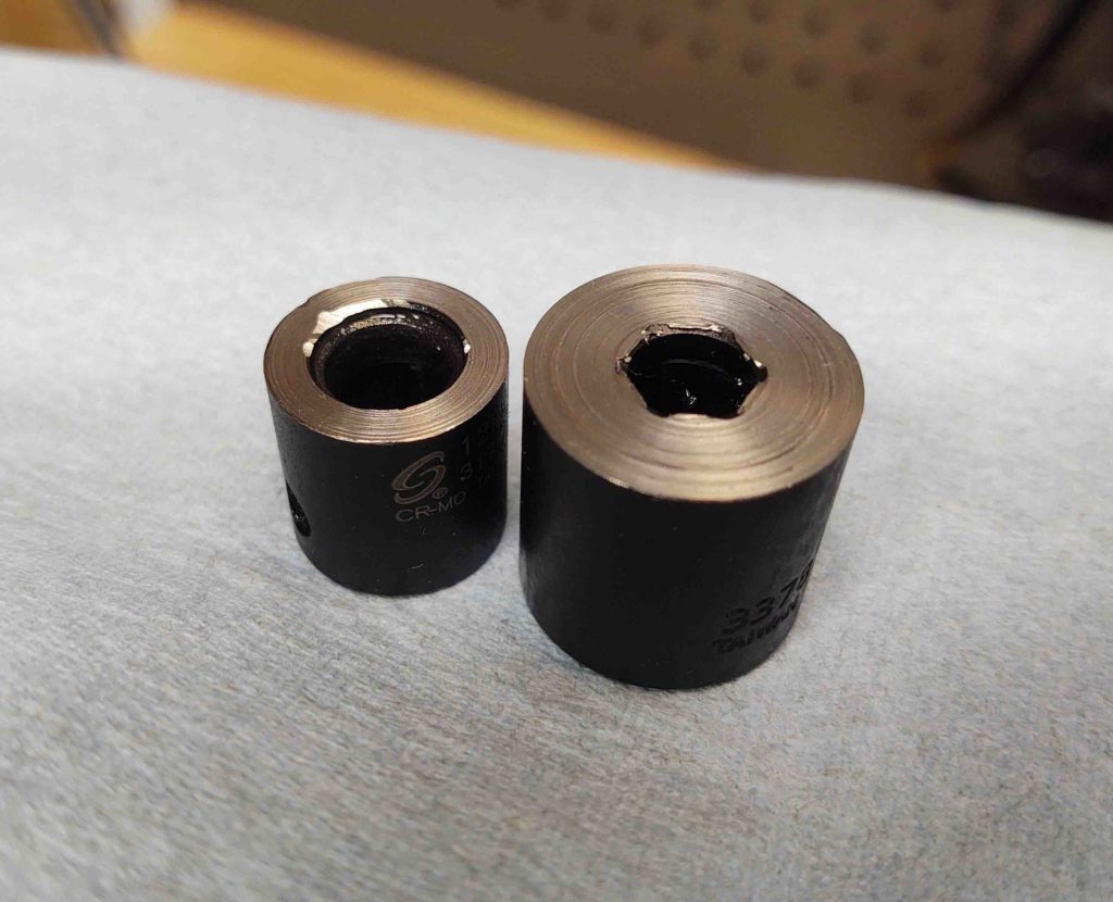
I was wrong. The 12-point 12mm socket simply did NOT fit on the 12mm square draw bar nut. Since I had the 12-point 12mm 3/8″ drive on hand, I simply spent a few bucks more to buy a 1/2″ drive socket, cut the business end of the sockets off which left me with the 3/8″ square drive side on one, and the 1/2″ square drive on the other.

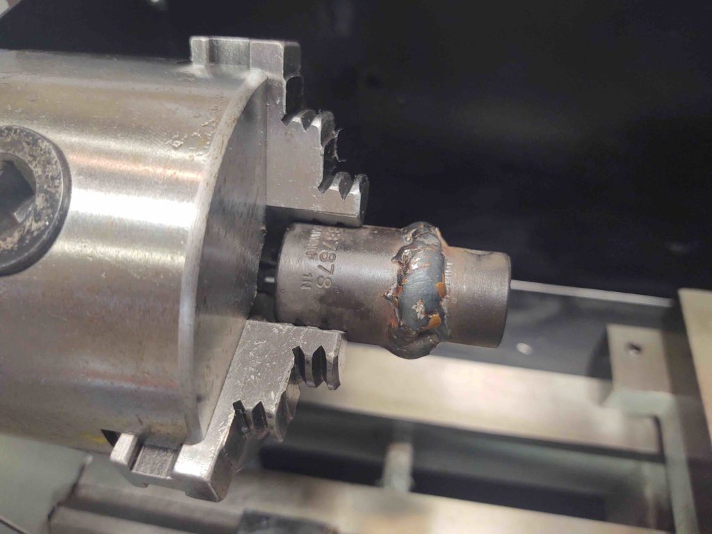
I then just needed to join them together to make one tool. That’s where this pic below comes into play . . .

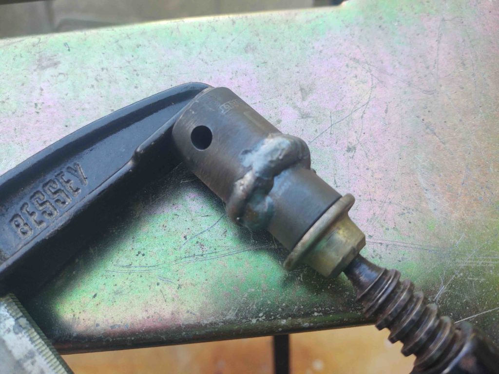
I determined the diameter of the small socket and subtracted it from the bigger socket, I then used the remaining value (halved, not as in my quick first swag below which was not correct) to scribe an alignment mark on the face of the larger socket.

After spending a good little chunk of time aligning the two sockets, I then ensured they were securely clamped together.

And then –with surprisingly even more Argon/CO2 mix left in my MIG welder gas tank– I welded the 2 socket pieces together.

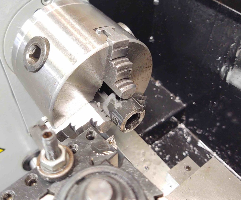
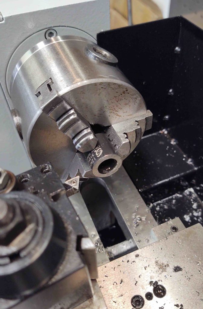
After the new welded oddball socket cooled, I chucked it up in the lathe to clean it up. Being a newb on the lathe, I was curious how much nicer I could actually make this thing look.

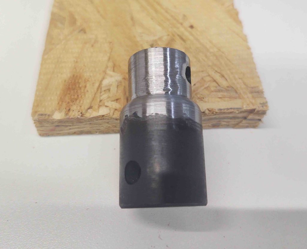
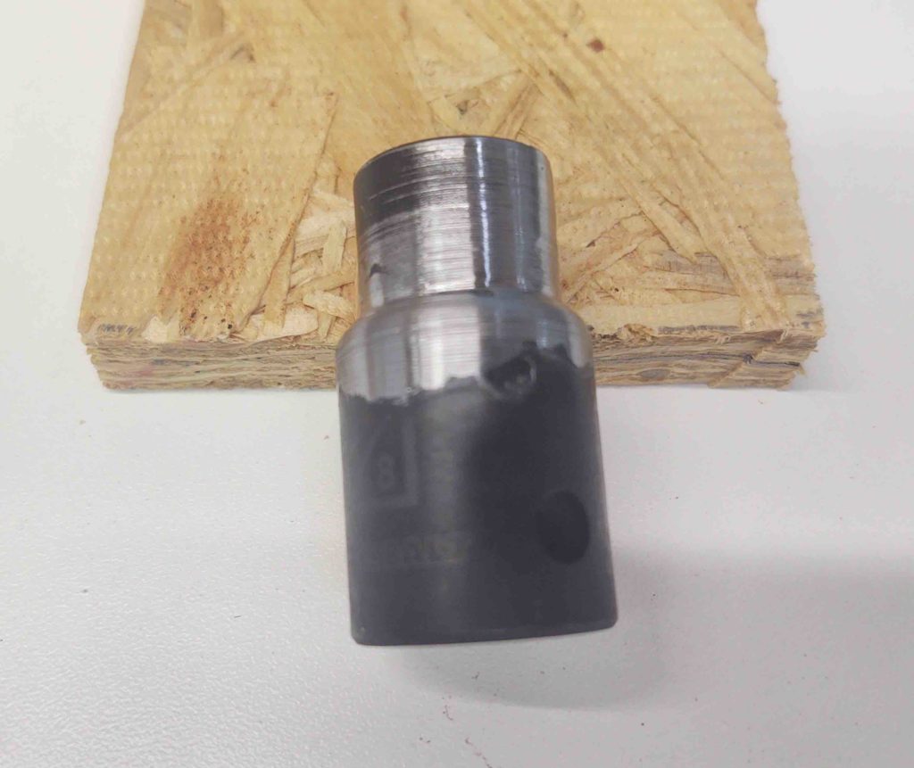
Not too shabby IMO. Not a superior part, but definitely good enough to get the job done and also not look hideous while doing it. I have to say I’m loving this lathe, and can’t believe I’ve gone so long without using it!

The pics show the different sides of the new mill power draw bar socket.

I then painted it black. Here it is a few hours later after the paint was dry.

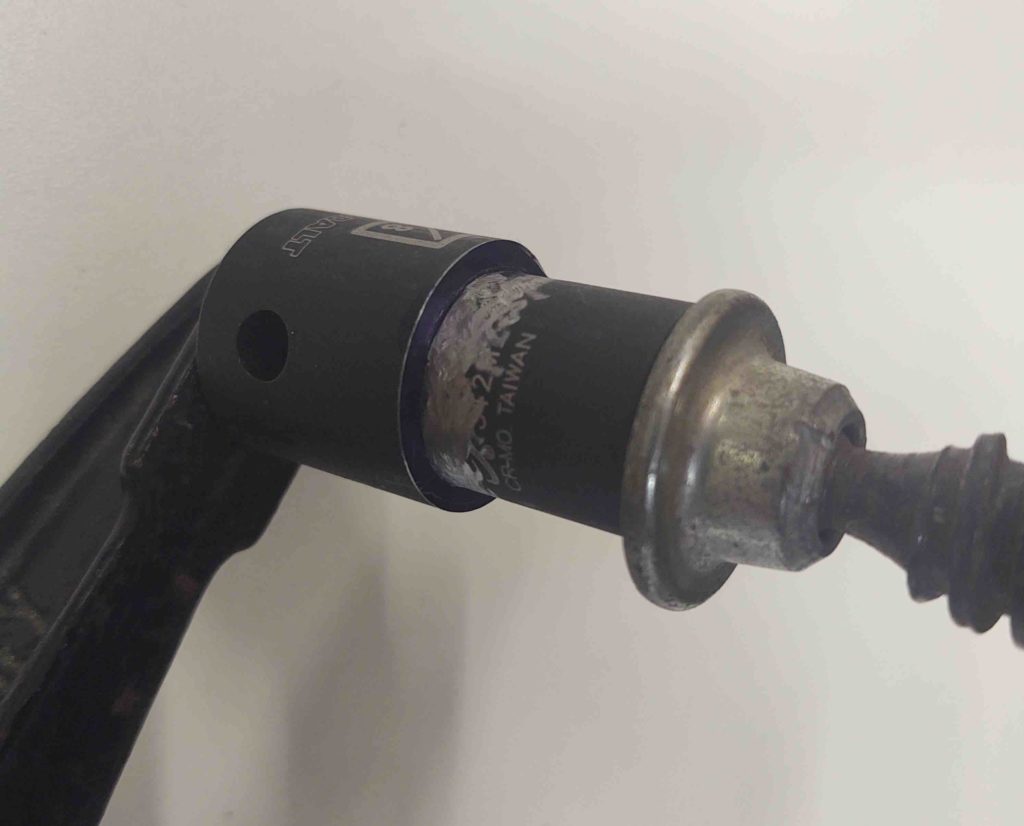
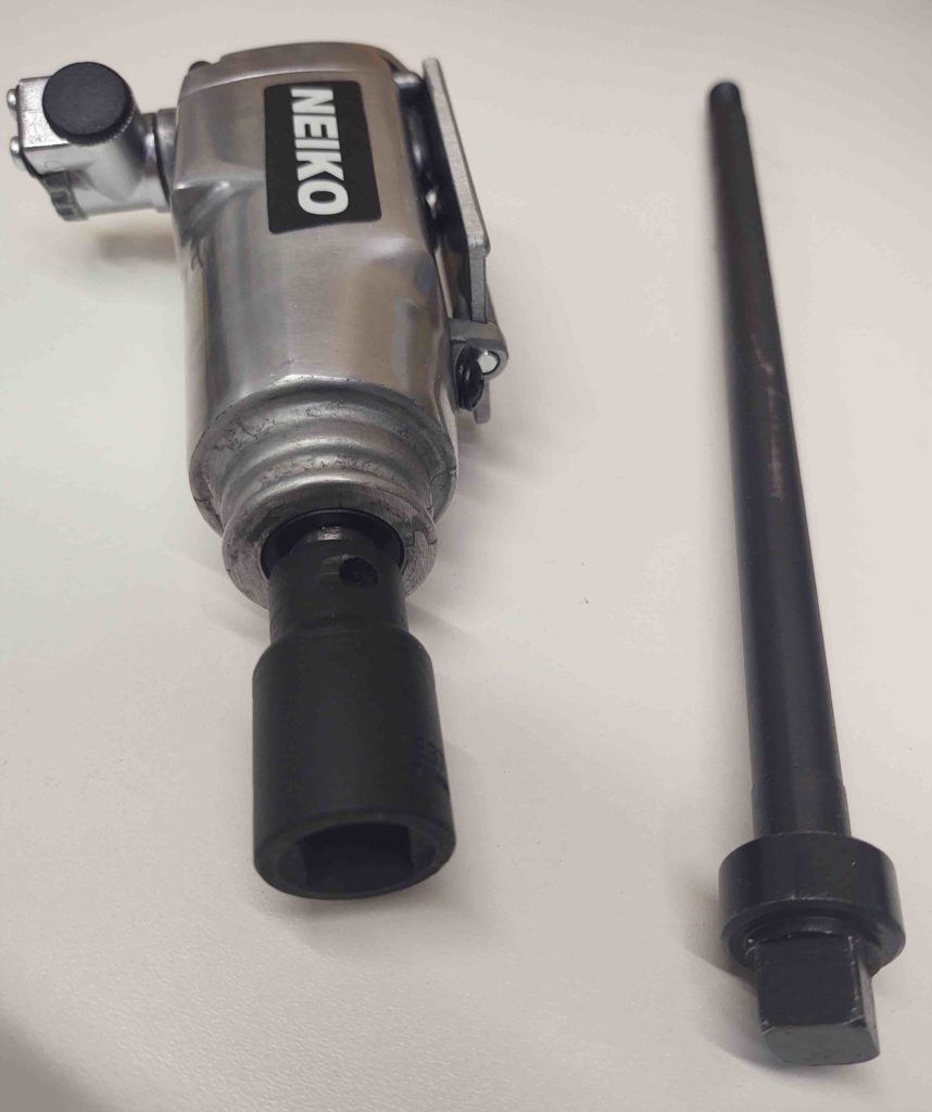
Here’s the new mill power draw bar socket attached to the 3/8″ drive impact wrench that will drive the quick tool change process for my mill. Lying next to the impact wrench is the mill’s draw bar, as you can the square 12mm nut on top.

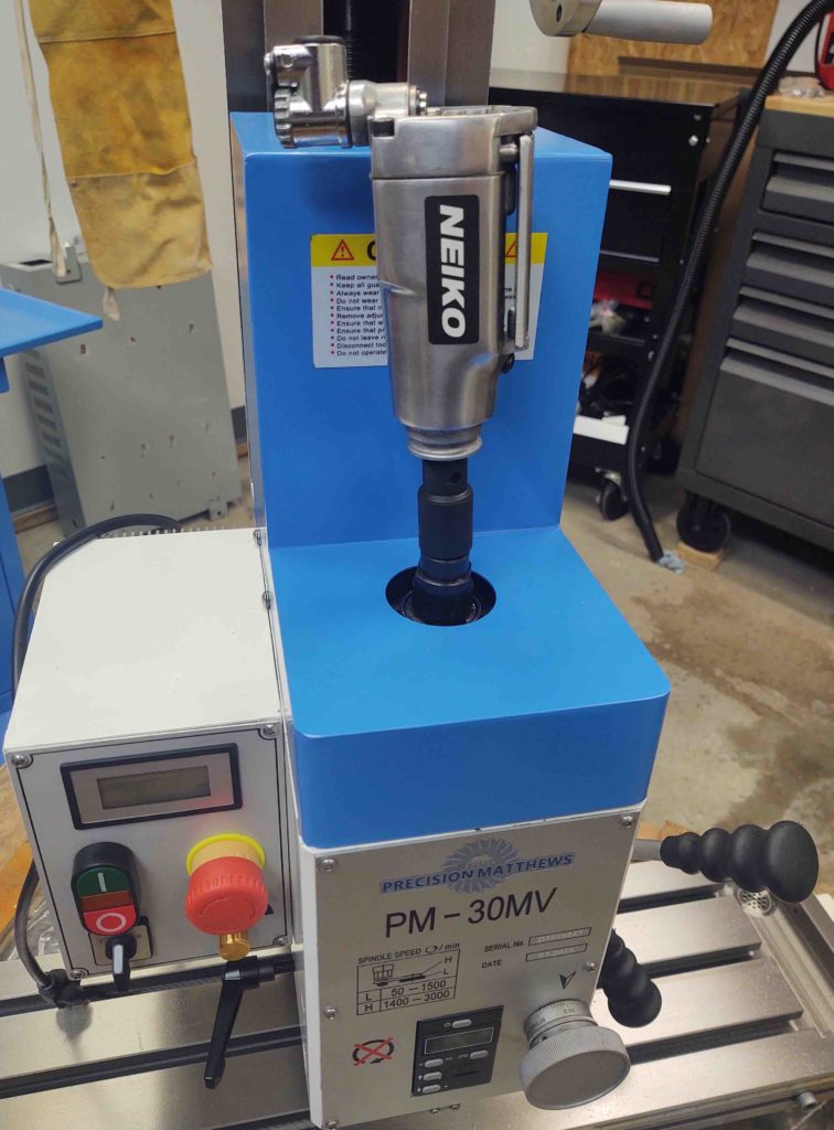
Here we have a quick mock-up of how this new socket will interface on both sides… to allow loosening and tightening the draw bar to release one tool and then tighten up the next tool during the milling process.

I’m very happy with this new lathe capability in the shop, and how this socket came out. With mini-projects like this it will help get me in the saddle quicker to tackle parts for the actual airplane.

As a point of note, as the new power draw bar socket was drying after having been painted, I worked on insulating the last big set of shop doors for a couple of hours. So just another couple of hours more and the insulation on those big doors should be complete.

Tooling Up – Lathe Mods

The weather finally broke and we got a rain free day for the first time in a while…. granted we’ve had some partial days of no rain to be certain, but of course with the ever-present threat and eventual outburst of rain.

I got some work done in the shop before I spent the good portion of the day hanging out with a friend’s daughter —my little buddy— mainly down by, and in, the water. It was nice to take a break, but after I was done I spent the rest of the evening finishing up the final tasks of installing the lathe tachometer mod I had made for the mini-lathe.

So besides actually converting it to CNC —can’t be done until the mill is operational— the lathe is installed, up running and fully operational by my standards.

It was a string of while doing A it’s a great opportunity to get B done steps in this scenario that helped lead me to complete this mod now… perfect while paint was drying:
The bolts that held the lathe to the bench top were too short so needed swapping out…
with the lathe off the bench again I decided to tackle a decent amount of rust and paint peeling off of the right rail support….
-while painting the bottom rail to have a quasi-uniform color I needed to remove the electronics control box….
-with the front electronics control box opened up it was a good time to install the tachometer mount….

The lathe is now virtually rust free (remember, it survived 2 hurricanes and a tornado!) and with no ugly chunks of paint half-peeling off. It now has a new tachometer as well, so I can document in a much more detailed/granular method my feeds and speeds as I dial in the lathe’s cutting of various materials, thicknesses, etc.

Moreover, I am done with mods on the lathe (until I convert it to CNC at some future point) and can simply use it now.

For any of you interested in the lathe tachometer mod (I know, I know… NOT airplane building) I documented the process in the following video:

The last two big tasks to getting the workshop online and airplane-building ready are
A) finishing up the last two sections of wall with insulation and top paneling, and B) getting the milling machine installed.

Back to work!

Tooling Up – Lathe Initial Cuts

The rain continues. And its continuing onslaught is quite out of character for a typical May in NC I’m being told… Moreover, it has now officially crossed into the really annoying stage (again, it’s raining as I’m writing this post).

Moving on . . .

Of course to do initial cuts on the lathe denotes that the lathe has been, in fact, installed. But instead of an attention grabbing post title listing yet another tool install, I figured I would highlight that some work is actually being done with these tools!

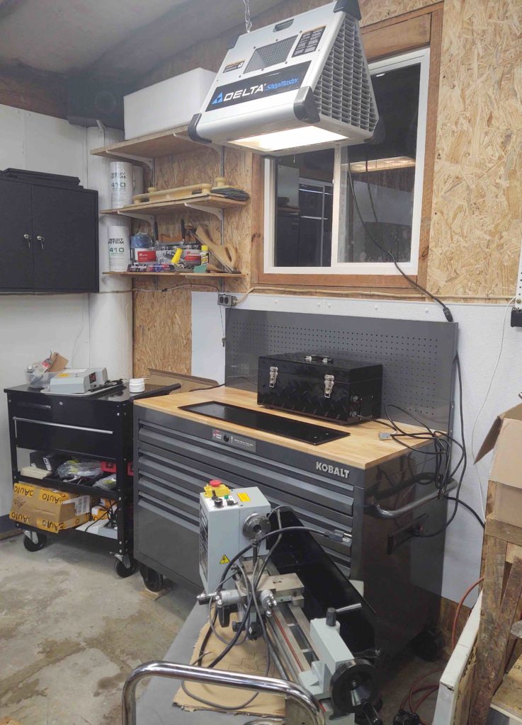
This install detour was in part due to the air filter and light you see hanging above the lathe station. I had cleaned up the big Delta shop air filter (no pic yet) that I pulled out of the garage and installed it on the other side of the shop. Since I had my ladder at the ready and drill set up for drilling the bigger holes in the joists to hang these filters, I pulled this one pictured below out from under the carport and cleaned up the ton of dust, dirt and pollen that it had accumulated.

I wanted to hang the air filter/light before I installed the lathe so the lathe wouldn’t be in the way nor get damaged while hanging the air filter.

After doing some mock lathe ops and figuring out a good front-to-back position that would allow acceptable access to the lathe CNC control box (black tool box), I determined my final lathe position with the chip tray set back 1-3/8″ from the work top edge.

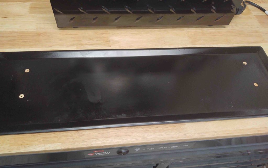
I removed the lathe (pic above) and then marked the 4 bolt mounting points through the holes in the chip tray.

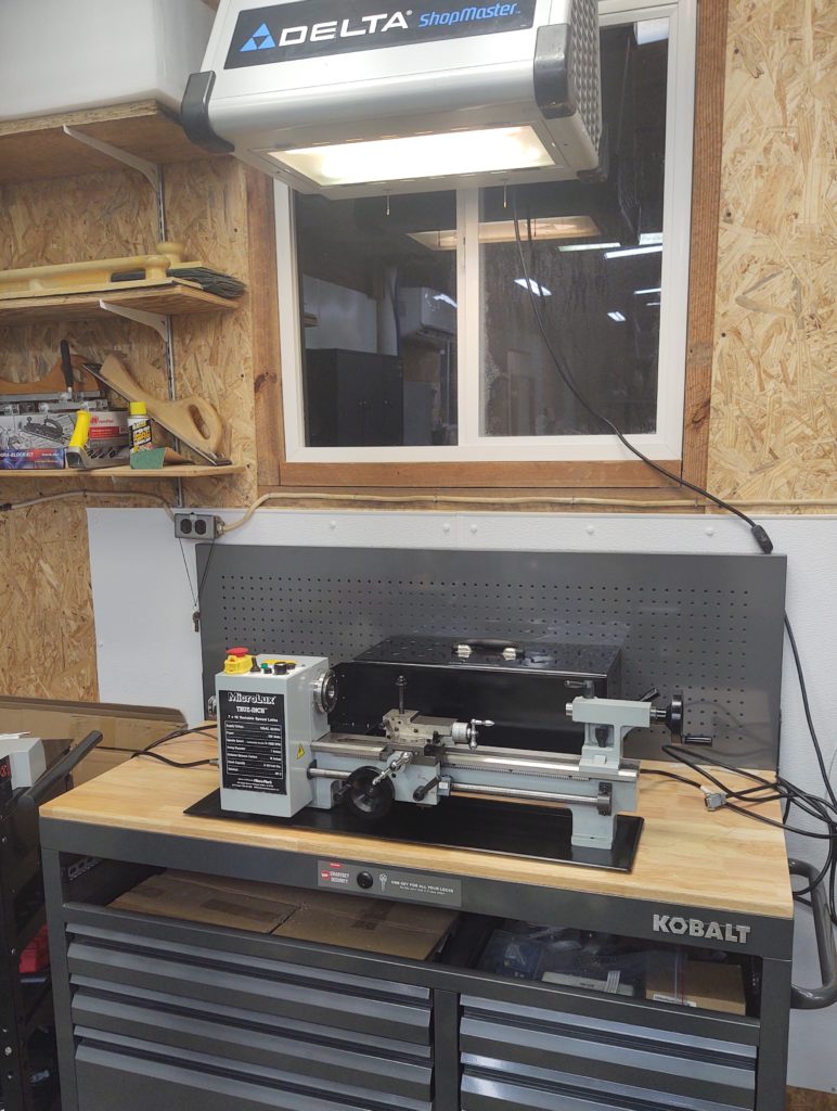
I then drilled out the 4 mounting position holes and mounted the lathe in its new official home atop its own work cabinet.

Now, I would say that I am technically in the midst of my milling machine install (again, these installs occurring now as brought to you by the insane amount of rain we’ve been having…).

As it turns out though, I both wanted to get a quick kill knocked out regarding the lathe install, plus get a part made for the mill…. and get that darn air filter/light from outside and installed where it could do some good.

You see, the mill’s draw bar (that holds the milling tool/collet in place) has a 12mm square nut on the top. I mistakenly assumed that a 12-point 12mm socket could fit on this square nut to then be driven by the small air impact wrench (3/8″ drive) –the heart of my new power drawbar solution.

Well, the 12-point 12mm socket does NOT fit the square 12mm draw bar top nut.

But an inverted 1/2″-drive socket, the square drive part–not the hex socket side, works a treat for driving the 12mm square draw bar nut. However, the glitch is that they don’t make (not that I’ve found anyway) 3/8″-drive-to-1/2″-drive “sockets”.

Well, good thing I have STUFF to make that myself!

I started by using a Dremel tool to cut off the 12-point 12mm socket side on the 3/8″ drive socket. Any 3/8″ drive socket would do, but since this was a single socket that I purchased specifically for this power draw bar, I used it.

With the socket end cut off, leaving me with the 3/8″ drive part of the socket, I then chucked it up in the lathe [in the stock 3″ chuck that was opened and “available”] and faced the ground off end to clean it up and square it for subsequent welding to the 1/2″ drive socket piece.

BTW, this pic was shot after the first of two passes…

Here it is after the second and final facing cut.

I was in a hurry and didn’t get a pic of the before state of the 3/8″ drive socket… but here is the final result for 3/8″ drive socket and a good before of the 1/2″ drive socket.

Actually this shot –although blurry– really gives you a sense of how irregular the ground surface is on 1/2″ drive socket. Of course the 3/8″ looked about like that as well before I put it on the lathe.

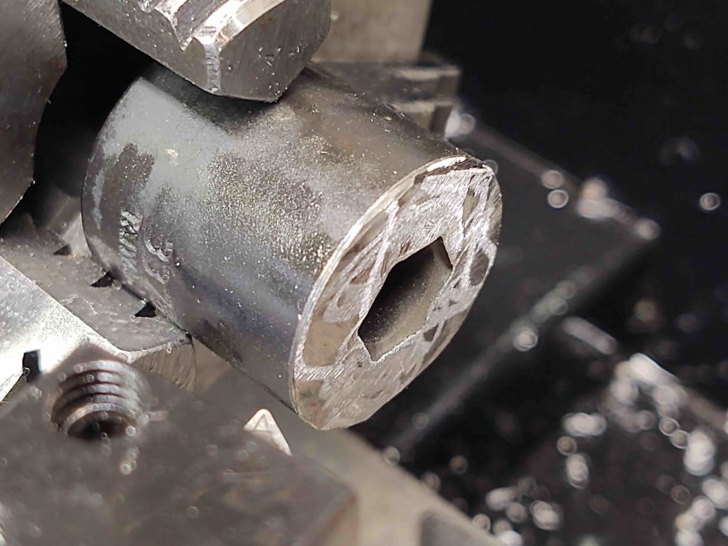
One last before pic, in the lathe chuck, of the 1/2″ drive socket before I faced it.

And after a couple of cut passes, the 1/2″ drive socket came out just as nice as the 3/8″ drive.

I normally like to show the end result of making a part before I post anything on it, just to make sure it went as planned and not waste time posting on a failed effort. But I wanted to show the lathe installation primarily, and I’m optimistic that the welding up of these two parts shouldn’t be too challenging for my Neanderthal skills!

Tooling Up – Big Tools

Over the last few days I’ve been able to make some progress on the shop. Although I did finish painting the frames of the last big set of doors that will get insulating, the rain came once again forcing me to close the doors earlier then planned.

[it’s raining now as I write this blog post]

Since getting the plasma cutting table installed and operational, I have been focusing on the next round of big tools that I’ve had planned for the shop for quite some time (AKA: years).

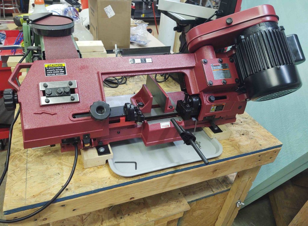
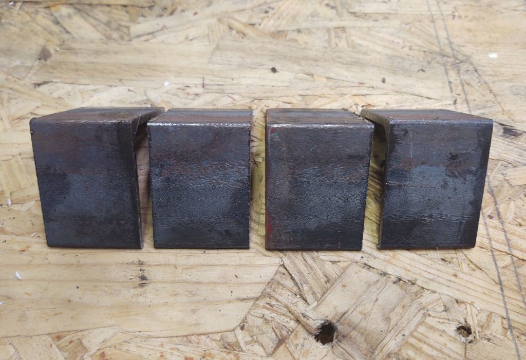
First off, I was able to finish making (and painting) the 4 mounting brackets for the Harbor Freight Horizontal Band Saw which then allowed me to mount it to the top of my mobile work bench.

I mounted the saw on a couple of 2x4s to raise it up higher, and thus allow a few things:

  • The chip tray to be slid into place underneath the saw (and removed to dump)
  • The saw to be rotated into the vertical position for blade changing and use as a traditional band saw
  • Most importantly, to rotate the left side wheel to clamp work into position

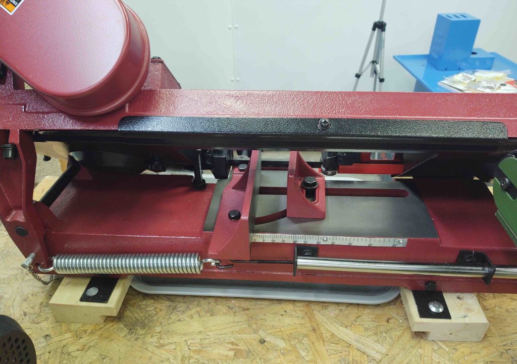
Here we have the back view of the band saw mounting.

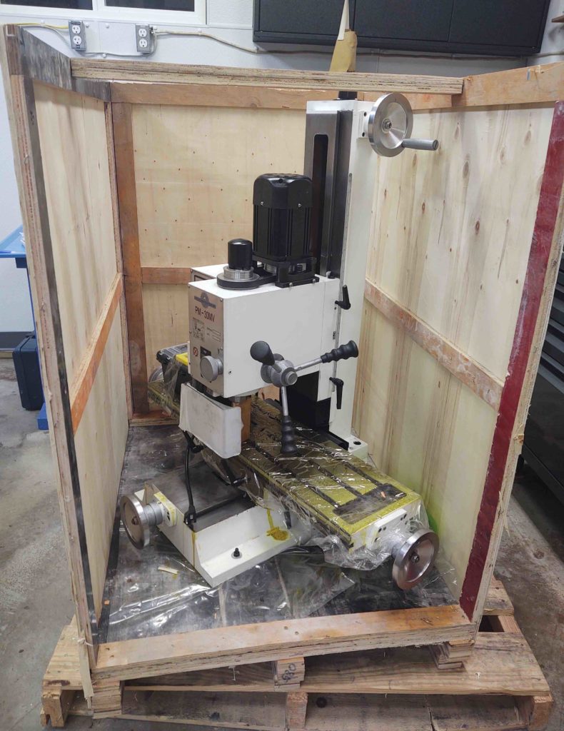
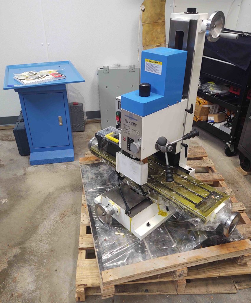
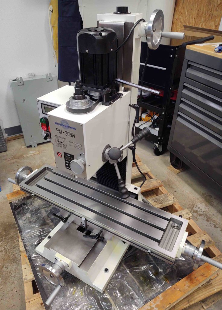
I then got to work un-crating my Precision Matthews PM-30MV Milling Machine.

Here we have the crate sides removed, and a lot of cleaning up to do on the mill!

(for a point of reference, the mill’s table is about 3′ wide . . . btw, not the blue “table” to the left, but the gold-looking surface in the middle area of the mill)

This gold shipping gel was not that bad to remove, except in the following pics you can see where it stained the white paint on whatever mill components it was in contact with.

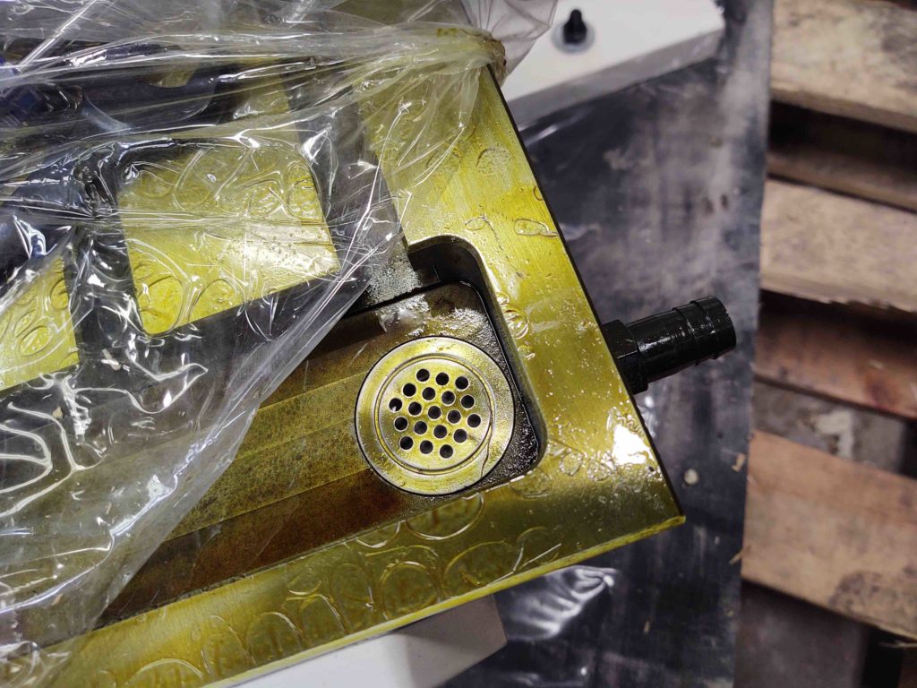
A notable surprise feature on this mill is a drain in the table for flood coolant, if I choose to employ that option in the future.

Analogous to the clear plastic guard on a table saw that rarely get used and is usually the first component dispensed with, my first official mod was to remove the clear plastic safety shield that rotates in front of the spindle before cutting. Unlike a table saw however, this guard is actually wired into the system via a microswitch that must be closed to allow the machine to turn on.

I removed the guard (below left in pic) and spliced the wires together with a butt connector.

I then spent a few hours cleaning the mill, primarily with WD-40. Albeit faint yellow blotches are still visible on some of the painted surfaces from the gold protective gel. I even tried acetone on those spots with seemingly little effect to remove the stains.

Oh, well.

Some of those stained components (hand wheel blocks) will be removed when I convert this machine to CNC, while other areas will be covered up in large part by aluminum angle stock that will make up the homing switch mounts. So I suspect the stains will be minimally noticeable when the machine is up and running. And let’s be honest, clearly it’s a cosmetic thing and doesn’t affect machine functionality in any way.

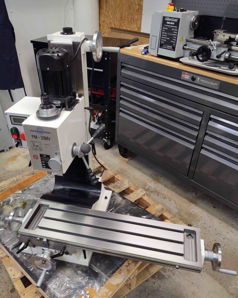
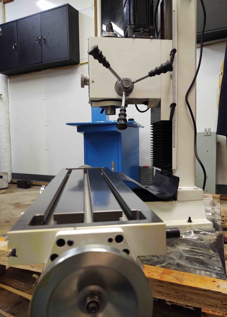
Although not as impressive in the pic vs seeing it in the shop, I was trying to show just how far out the table can extend both to one side on the X axis (here, to the right) and all the way forward on the Y axis.

This provides a sense of the Y axis spindle alignment with the back of the table when the table is full forward.

Finally, I moved the mill head all the way up to get a sense of the height achievable on the Z axis. Not bad…

I will continue to work installing both the mill and the lathe and their respective CNC systems, while also insulating the remaining walls when the weather allows it.

Tooling Up – Horizontal Band Saw

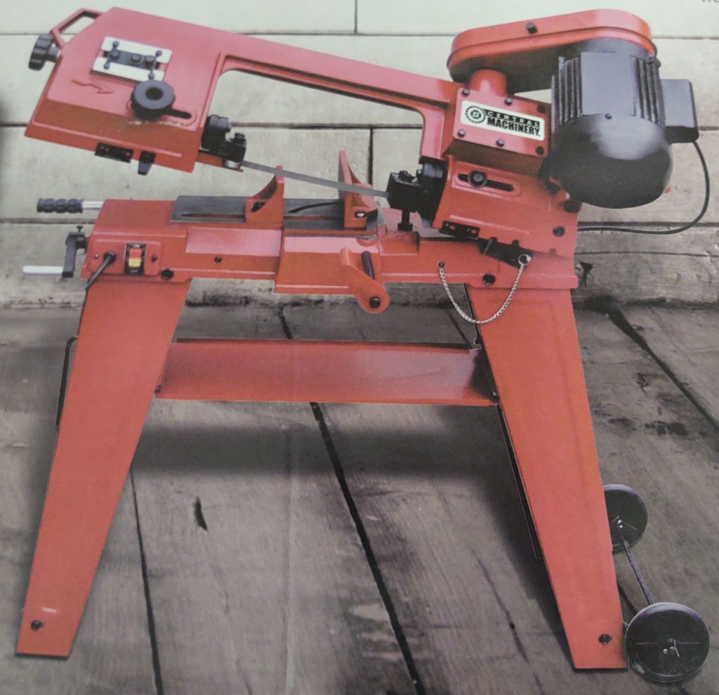
I recently ordered a horizontal/vertical band saw for cutting metal stock to then be either milled or lathed. Buying long stock of metal is typically cheaper and it’s always good to have extra on hand for an unexpected part that needs to be made impromptu.

I was researching which saw to buy, shying away from the cheapest, smallest model that was offered at Harbor Freight –4×6 inch– when I noted there was a $60 sale online. Being cheap, I started investigating the use of this specific saw, which is sold under a myriad of different brand names: WEN, Hobart, Eastwood, etc.

I found it to be quite the prolific little saw that could… with what is akin to a cult following in many respects.

As with many Harbor Freight tools, the mods and upgrades are countless… again, one starts with a baseline Harbor Freight tool that isn’t that great coming out of the box, does a few tweaks and upgrades that typical results in a very capable machine.

Having just visited a Harbor Freight store for other stuff, I knew that this saw was mounted on very short base… which meant two important things to me: A) a lot of bending over to use it and, B) finding a spot to put this thing in my shop.

Nonetheless, having checked the local used market (Ebay, Craigslist, etc.) the price was just too good to pass up (under $200) and I pulled the trigger to have one delivered.

Having had it in the box for a good week while I assembled the plasma cutter and got it online, when it came to unboxing this small but heavy beast I discovered that somewhere along the supply chain it had been obviously dropped… hard. The entire lower end of the motor was crushed.

So after a few calls to local Harbor Freights I found the store in New Bern had one on hand, so I loaded up the smashed-up one and ran up to New Bern to swap it out for one in good condition . . .

You’ll note in the video (below) that I decided to mount it up higher on my mobile work bench in the spot just recently vacated by my lathe. My mounting choice resulted in ZERO added footprint in my shop for this new capability!

Testing out the saw as I had it temporarily clamped to the workbench it made quick work of slicing through 2″ x 2″ x 1/8″ angle iron. Call me impressed! I’m actually using the 4 pieces I cut to make brackets to mount the saw to the top of my mobile work bench.

Moreover, I have to note that this saw was dialed-in pert near dead on right out of the box!

Enough banter. Here it is:

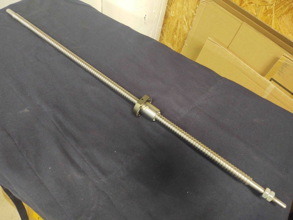
In other news, I received my new Z-axis Ball Screw that I spec’d out and then special ordered for the lathe CNC conversion. This is the last externally supplied component that I’ll need to convert the lathe to CNC as I’ll still need to machine parts for it in house.

So the push continues to get the shop insulated, equipped, outfitted, tooled, up and running to finish this protracted airplane build.

Chapter 26 – Seat Core Check #2

Although certainly one the easiest, least-difficult tasks in building this airplane, the Seat Core Butt Test, or SCBT (I just made that up…ha!) is something that requires a good chunk of time to be allowed for…

Well, I started off this morning with a goal of completing a long-overdue email reply to my buddy Dave Berenholtz. He was discussing his seat cores when it dawned on me that I should finish my email to him while actually sitting in –and testing– the latest Oregon Aero mods to my seat cores.

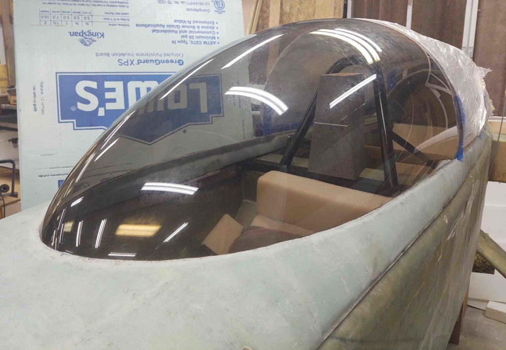
One of many issues Dave is having with his Oregon Aero seat cores is clearance between his head and the canopy while sitting in the front seat with the cores in place. Here I’m showing that I have about 4 inches of clearance above my head while sitting in my front seat (obviously with seat core in place).

One of my issues with the initial version of my seat cores –both front and back– is that the upper seat pad did NOT follow the “curve” of the seat where there was 4″ vertical section on the front seat at the top (and ~6″ vertical section on the back seat).

Well, Oregon Aero corrected this on my latest version 2 seat cores, as can be seen below through the canopy (and in my previous blog post) . . .

With the uppermost portion of the front seat pad now in place, it pushes my shoulders both up and forward in the seat. Lending itself to the first definite reason I needed to check head-to-canopy clearance with the new seat core.

The second verification check was with visibility, which there is a noticeable improvement for the better. Not much, but definitely better vs worse, both to the front and sides. In fact, I can almost see the top line of my nose hatch while sitting in my normal position inside the cockpit on the version 2 seat core pads.

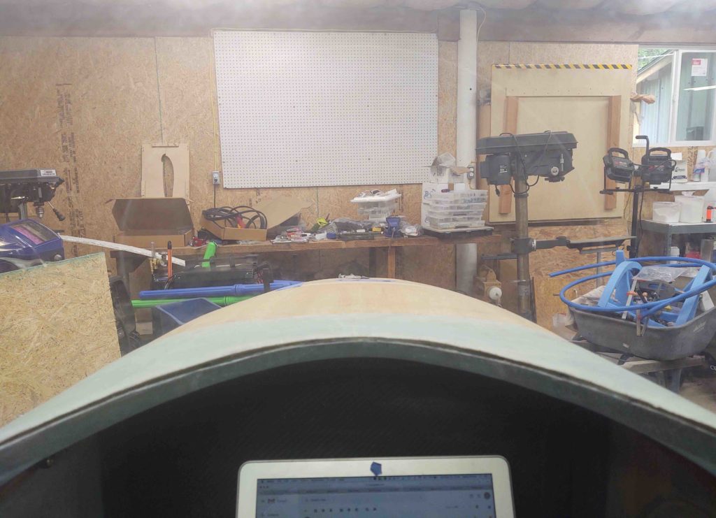
Clearly (as in contrast to my dirty canopy) the visibility is excellent. This is due in part to my having moved my seat almost an inch forward at the very early stages of fuselage construction.

I have a very old MacBook Air that has terrible battery life, but it’s small so I was using that to pen my reply email to Dave for about the first half hour sitting on the front seat core.

Well, as the laptop battery was getting to it’s last breath, my daughter serendipitously called which gave me something to do for another 45 minutes!
Thus, for this “Butt-in-Seat” test I spent over 1 hour and 20 minutes sitting on the version 2 seat cores. Honestly, I could have used a little bit more lumbar support, but upon exiting the plane my hips didn’t feel as they did somewhat after the first seat core check (at least a few hours later).

Speaking of exiting, with the new lower profile front edge of the front seat it was very noticeably easier entering the plane with these modified seat cores. I still caught my right heel on the way out, but I don’t have my seat cores secured/velcro’d to the thigh support as I will when the bird is flying.

Exiting is still not optimum, but it gives me some much-needed thigh support while still much easier to exit than version 1 of the seat cores, so I can definitely live with this setup. And not to be snotty about it, but the majority of my buddies that are telling me to whittle that front seat edge thigh support down to a razor’s edge for easier egressing are notably shorter than I am… and I think their requirement for thigh support is an inherently different configuration than with me and my longer legs.

Bottom line, I would say that I’ll look at a bit more for lumbar support for longer flights, but I consider this seat core version 2 butt test a successful one!
Tooling Up – Dialing in the Plasma Table

This post is really just a string of videos walking any interested viewer through the steps I took to dial in my table and bring it online operationally.

I’d like to point out that it continues to rain here ad nauseam, so this is a good opportunity to bring the plasma cutting table online.

This video covers the water table and a somewhat boring overview of draining and refilling it.

I then show the initial steps breaking the table in, with a specific break-in CNC program provided by Langmuir Systems.

Those that have followed my airplane build progress know that Marco and I used his Crossfire plasma cutting table as a plotter to print out the CAD file of my instrument panel.

A very cool ancillary capability of these plasma cutting tables, and I’d like to repeat that on my own table.

In addition, this initial “plotting test” allowed me to see if the table was implementing the GCode via the CrossFire CNC control program… so a good test all the way around.

The following video is a fairly short one showing the initial manual test fire of the plasma cutter torch via the FireControl software.

Spoiler alert: it was successful!

Finally, the most arguably important video of all these: Initial Cuts on the plasma cutting table.

Not surprisingly, I had a fair number of early-on fails.

But with a little perseverance, a LOT of research and some help from a buddy of mine (betcha can’t guess who!! ha) . . . I got through it and actually started making decent cuts.

Full account here… (I couldn’t get this video to embed here for some reason).

These will probably be the last of the plasma cutting table videos I make for a while, unless I’m cutting a part specific to the Long-EZ build.

I will point out notable highlights of significant increases in workshop capabilities as they occur, such as this, but I certainly don’t want to belabor these points any more than necessary.

I will note that most of these videos also serve as both helpful resources (hopefully) to others as I have been definitely been helped out myself, and –moreover– serve as a historical record so a year from now I can answer the aged old question: “What the heck did I do? And how the heck did I do it??”