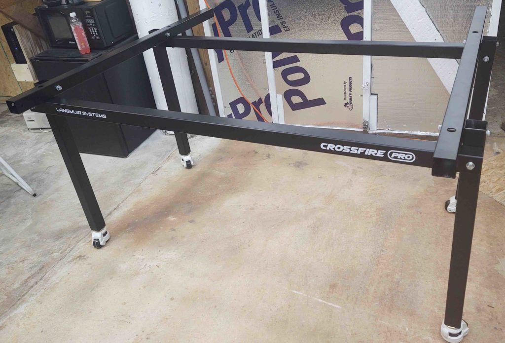
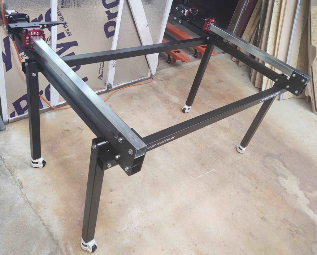
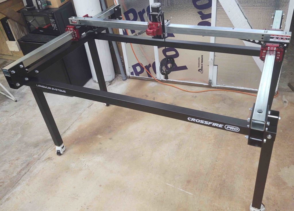
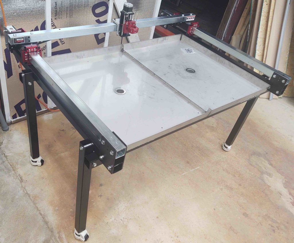
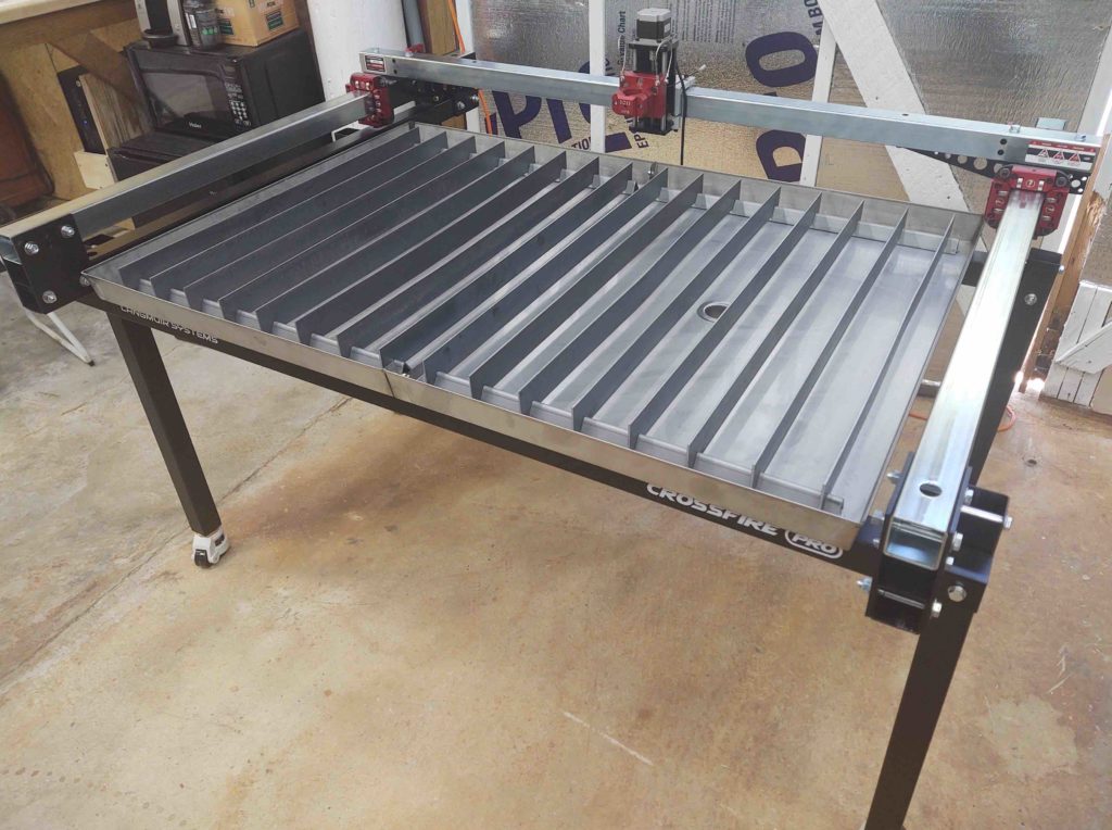
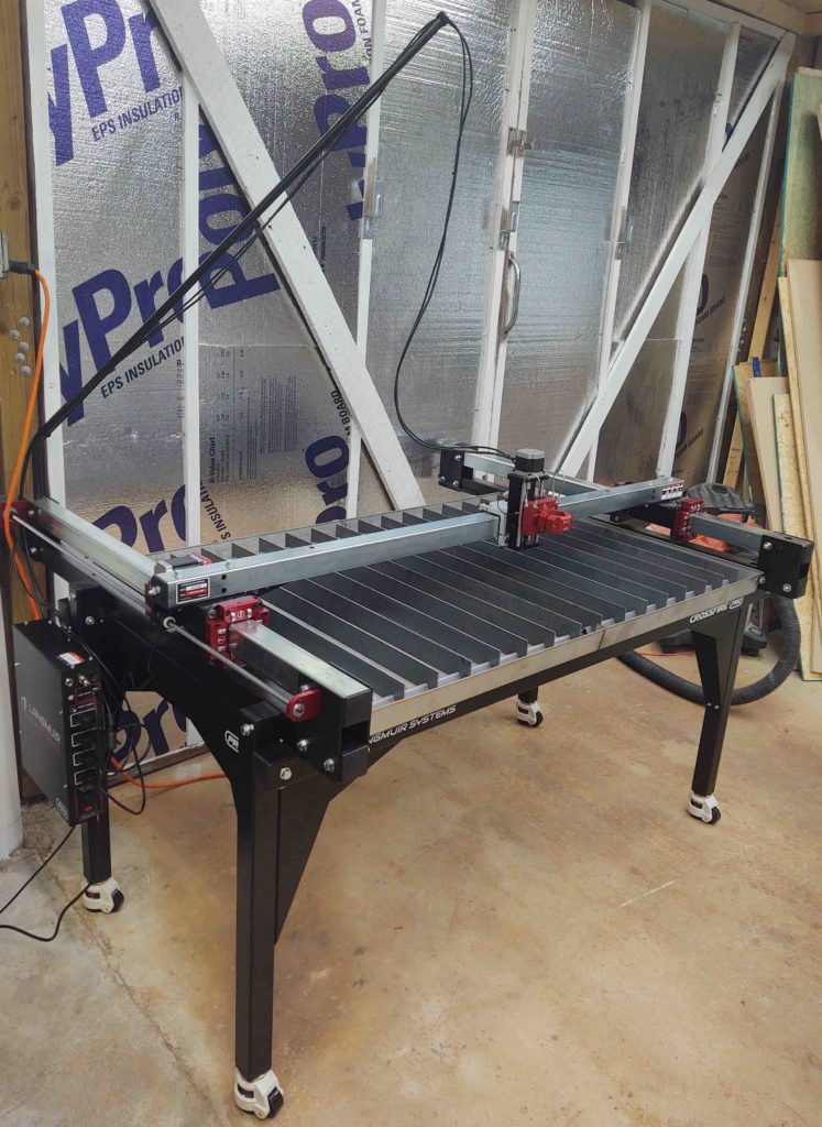
I’m going to start off this post with a video overview of the finished plasma cutting table. Please watch this because I also discuss the status of the workshop and my build.
Over the last few days I’ve finalized the assembly of my plasma cutting table, to include a number of tasks to both break-in and dial in the table.
After the initial assembly of the official table, I got to work on the construction of the bottom shelf. With the metal tubing I ordered [which now had a fair amount of surface rust from the copious amounts of rain we’ve been getting] I began cleaning the weld joints and welding the rectangular tubes together.
I have to say I’m tickled pink to have used the very last remains of the Ar/CO2 gas mixture that was left in the MIG welding tank from –again– over 10 years ago! In addition, I used the same exact wire spool and gun CONSUMABLES from 10 years ago as well.
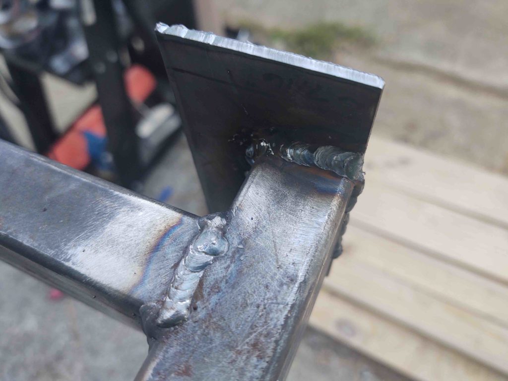
That was the last time I MIG welded, so I’m quite pleased with the outcome. My welds ranged from unspeakable on a few to ok on many and not that bad on a few more. Overall? Definitely strong enough to do the task, and too ugly to win any awards that someone would intentionally want to win!
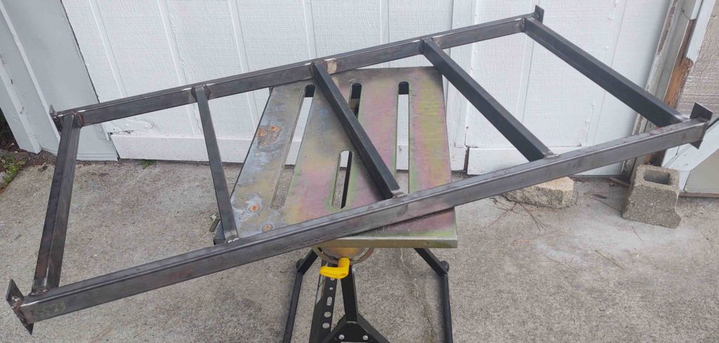
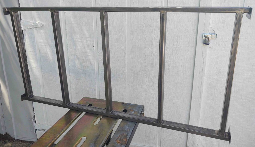
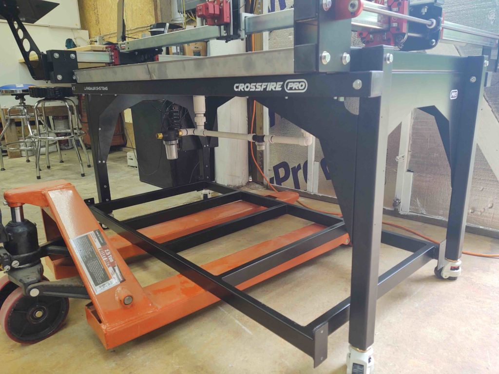
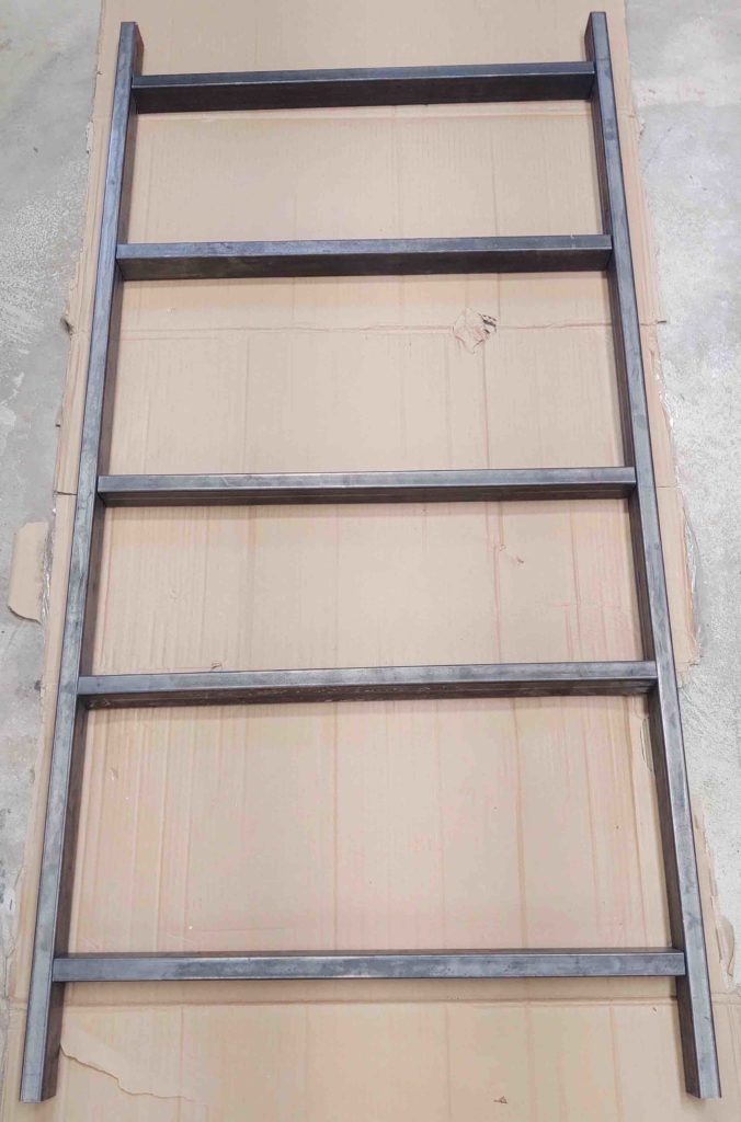
Here we have the completed plasma cutting table bottom shelf frame, all welded up and ready for some serious surface rust removal.
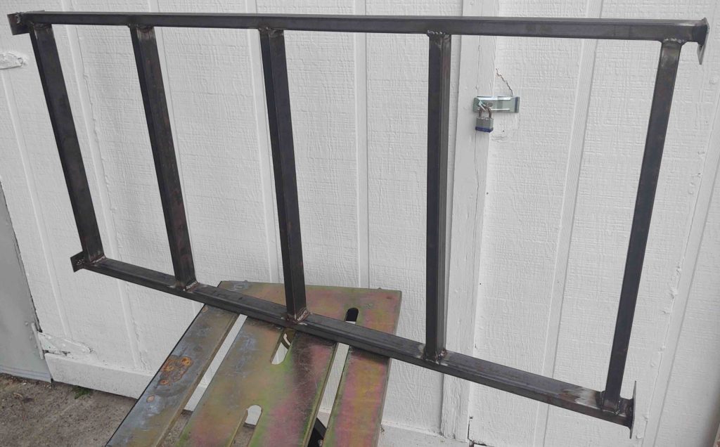
And another shot of the plasma cutting table bottom shelf welded frame:
I then spent a good hour + grinding down all the ugly protruding top and bottom surface welds. My primary concern were the top welds so that the shelf panels could lie flat, and specifically the top welds at the corner tabs that might also prevent the shelf panels from laying nice and flat.
The good news is that the self panels fit really well, and here we have one removed to expose the copious amounts of grinding to make this shelf work… ha!
The next day I started off going ugly early by undertaking the grueling task of removing the surface rust off the entire shelf frame…. this took nearly 1-1/2 hours.
I then cleaned and primed the shelf frame.
I later hit the shelf frame with a few coats of black paint and let it dry overnight before mounting it to the underside of the plasma cutting table.
I used 2 holes total on each shelf frame corner tab, an upper and a lower, as guides to drill the holes in the table legs. I then widened the frame holes out to 1/4″ and the leg holes out to 3/8″.
I then used RivNuts in the legs to “secure” the table frame. I put secure in quotations because the bottom shelf actually “floats” underneath the plasma cutting table as to not put any stress on the table legs, and thus risk misalignment of the upper part of the table.
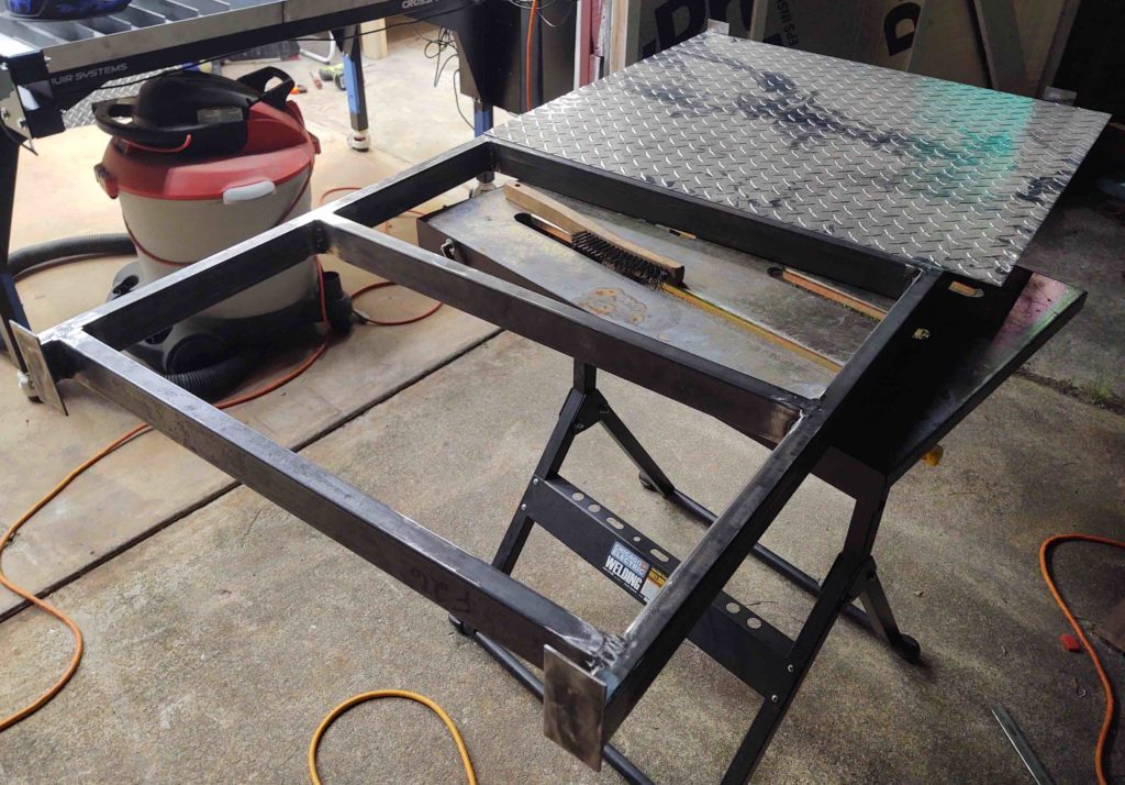
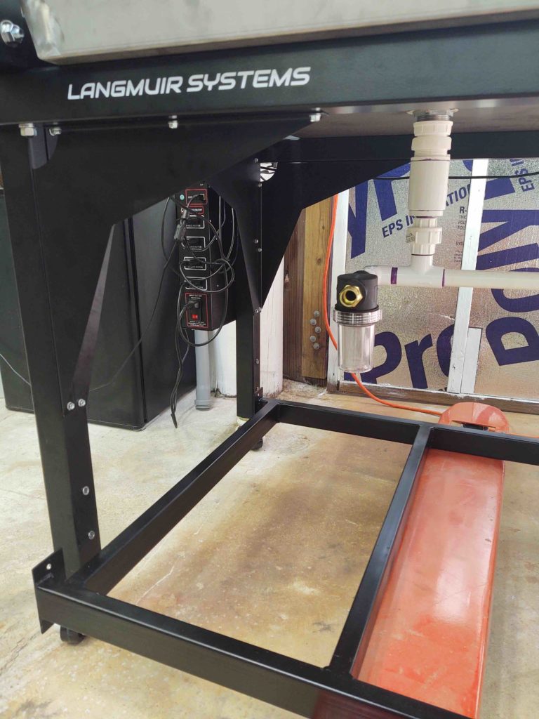
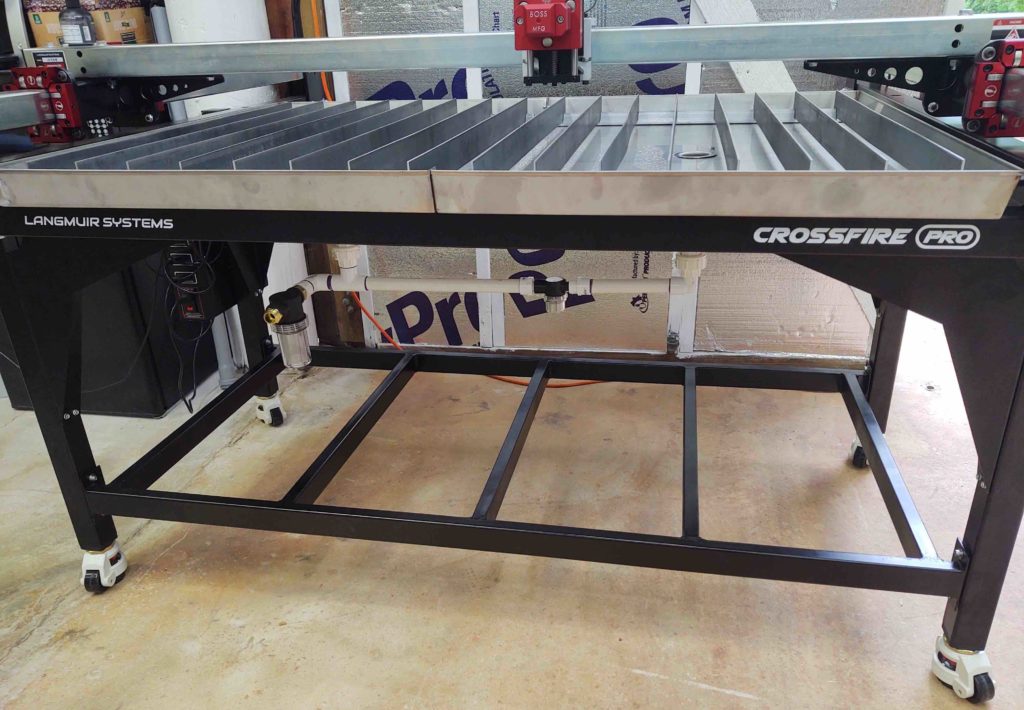
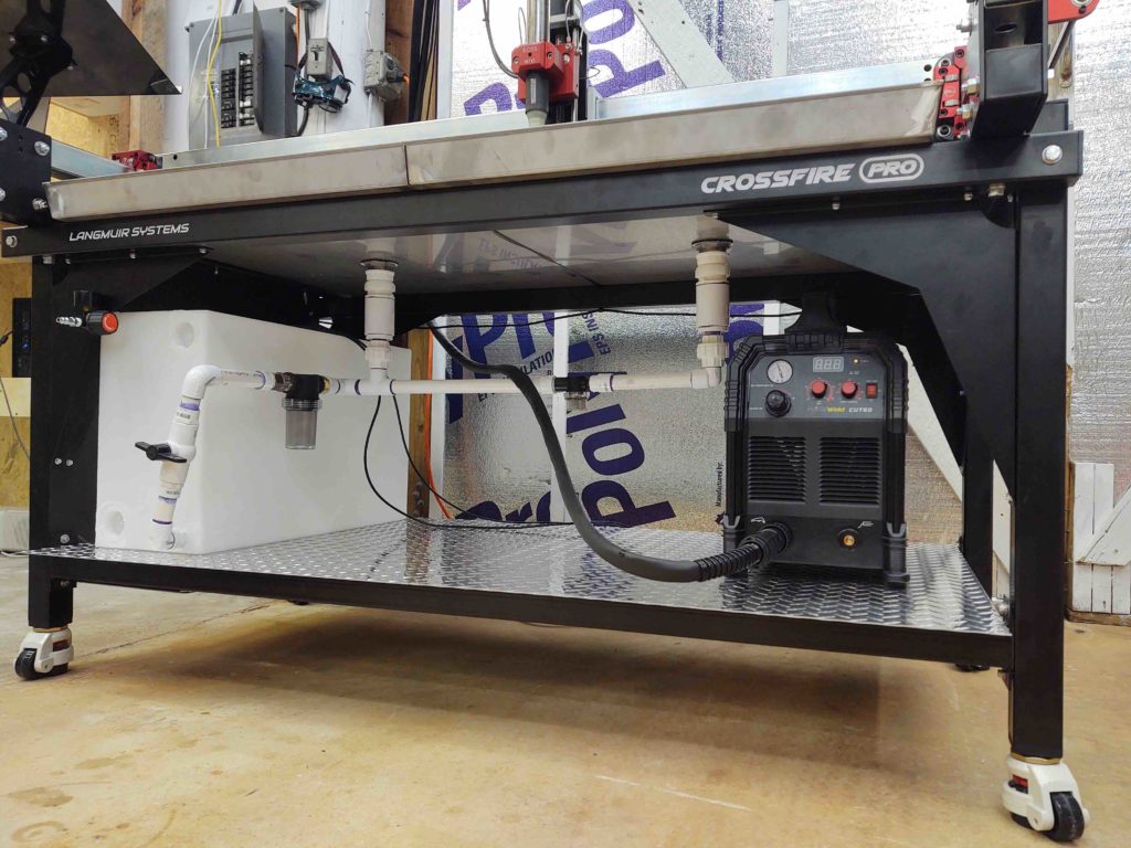
Here we have the lower shelf welded, painted and installed!
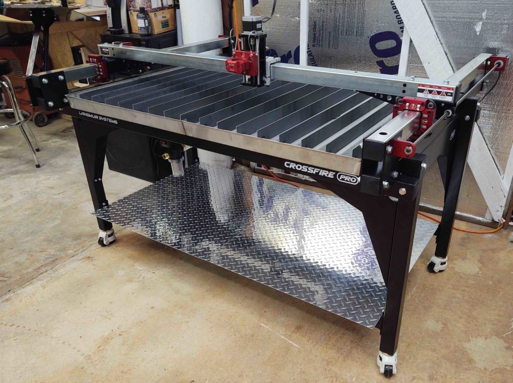
I then set the lower shelf panels in place and drilled and screwed them in place along the back edge. I eventually want to remove the shelf panels and bend the front 1″ down 90º to create a nice radiused front corner edge.
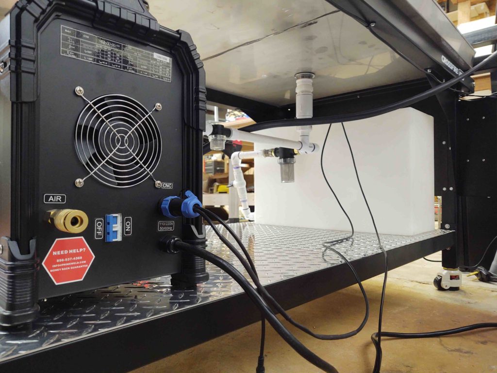
I then set both the plastic water reservoir (tank) in place, finished the underside water table drain/fill plumbing, and ensured the plasma cutter placement was good for the machine torch’s cable length (it was).
I also installed the CNC plug connector in the plasma cutter’s backside CPC port. I then ran the torch fire cable and the Torch Height Control (THC) cable.
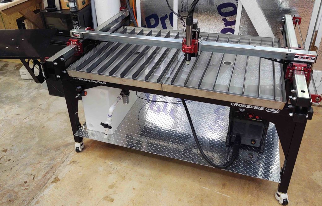
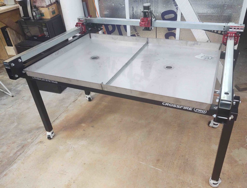
And Voila! The Langmuir Systems Crossfire Pro plasma cutting table is ready for break-in, check-out and dialing-in to get this beast up, running and cutting parts!
With the plasm cutting table complete, I will leave you with yet another video I shot about a month ago when I tested out the PrimeWeld Cut 60 plasma cutter:
Although I’ve put a fair amount of time and effort over the last 6 weeks into this project, I’ve kept it a fairly close-hold secret since I didn’t want a lot of hullabaloo over it until it was pretty much in the bag.
I actually pre-ordered this Langmuir Systems Crossfire Pro plasma cutting table back on November 1st of 2019, at a much reduced cost for ordering early and then be willing to wait 6 months until delivery. Although at the time I certainly wasn’t aware of just how much work was in store for me on the shop, I knew it would be significant so I didn’t mind the wait… and needed time to prep for the table’s arrival anyway.
With a quoted April delivery date, activity started picking up at the end of March. I started getting notifications of impending deliveries and also received some plasma cutting table accessories: the laptop stand and the Torch Height Control (THC) system.
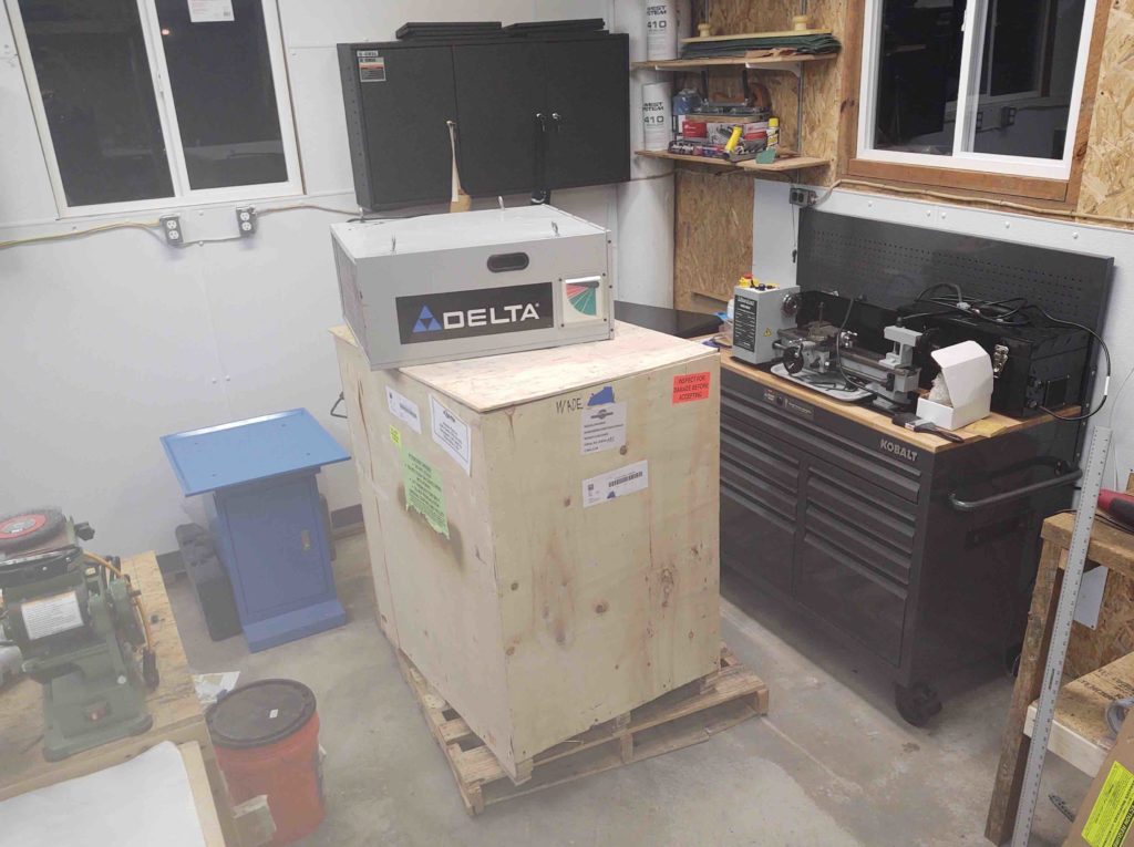
About a week into April I received the first of 3 big boxes that would make up the actual plasma cutting table, and they actually arrived in the exact reverse order of box number.
Box 3 contained the two stainless steel water table halves and the table frame corner gussets and end aprons.
As soon as I started receiving notifications that the plasma cutting table order would in fact be delivered in April, I downloaded the assembly manual and started monitoring the forum to ascertain any quick build tips and also get a heads up for anything I might should have on hand prior to parts arriving.
Not surprisingly, the Langmuir Systems forum was a treasure trove of information, with many members posting truly great ideas on how to mod these tables to really improve their functionality.
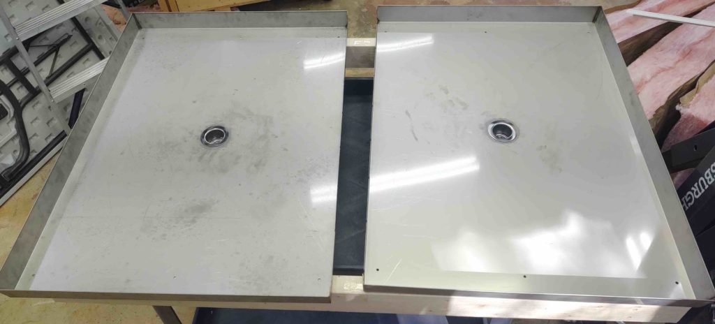
One such mod was to chuck the stock water table drains (there are 2 drains since there are two table halves with a raised lip in the middle where they are bolted together) and use much larger drains. Moreover, after the bigger drains are installed then PVC plumbing could then be used to drain the water solution from the water table to be stored in a large plastic tank… and then pumped from the tank back up into the table when it was needed for use.
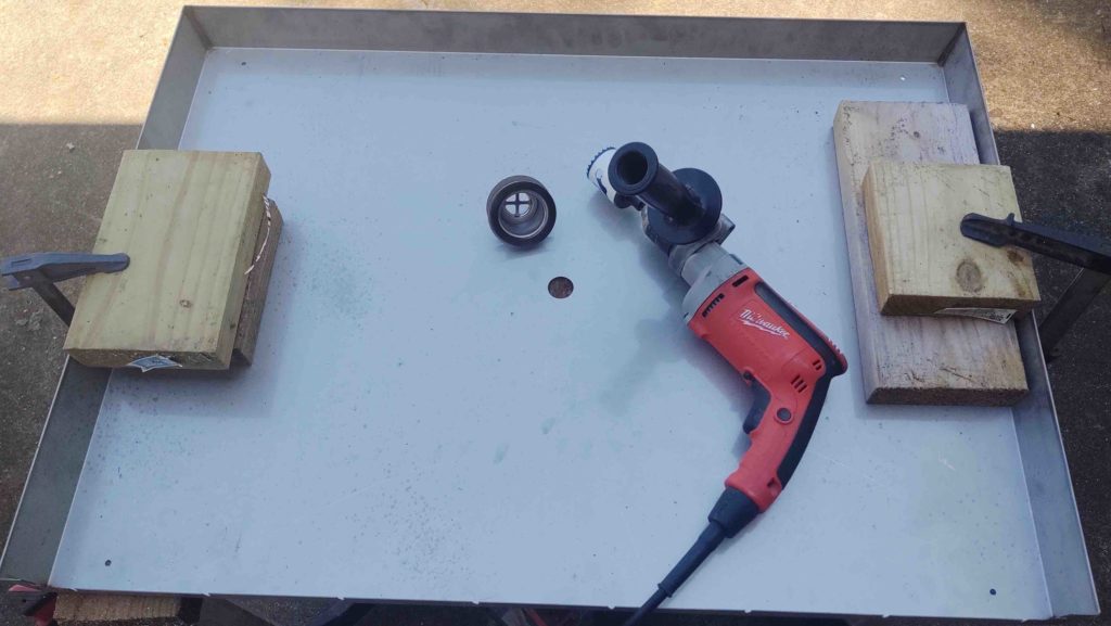
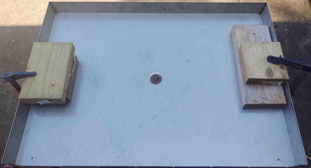
I decided to do what I could as components arrived, so within days of the water table being delivered I drilled the table drains larger to accommodate some bar sink drains I had picked up at Lowe’s.
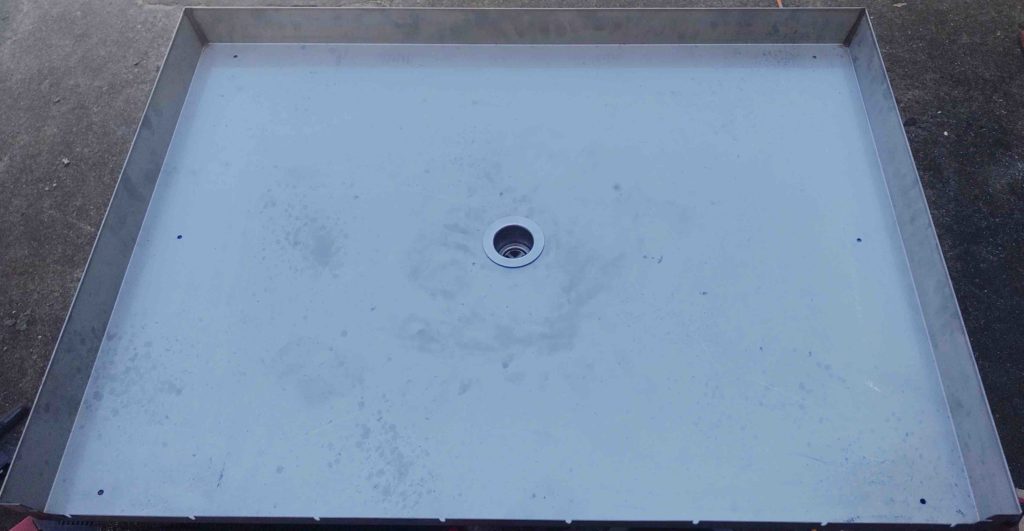
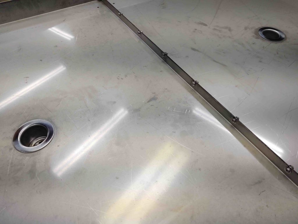
I then mounted the bar sink drains with plumber’s putty and built a 2×4 frame to mimic the frame of the plasma cutting table.
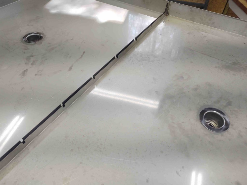
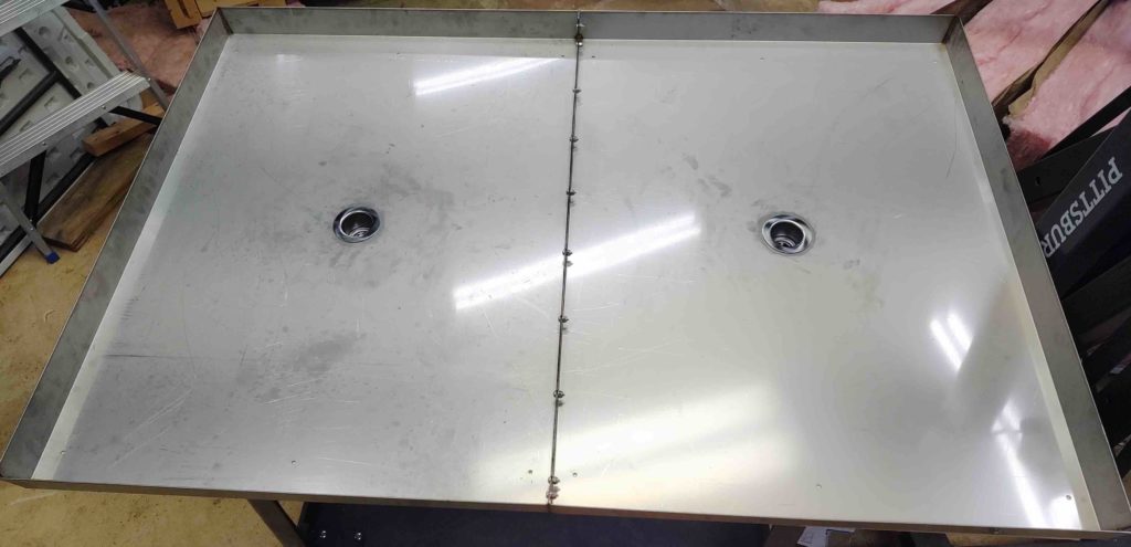
You see, the water table halves were meant to be joined on the plasma cutting table using a tube of supplied silicone, with stainless steel hardware. The problem was that the supplies required to join the water table halves together came in Box 2, which hadn’t arrived yet.
I had already noted that a number of Batch 1 customers (I was/am Batch 2) were not overly happy that in using the supplied silicone were left with leaky water tables. One forum member noted that in his job working on boats he uses 3M 4200 sealant, and that it had worked a treat on his table with no ensuing nor offending leaks.
So although not cheap, I had the 3M 4200 sealant in hand after ordering it from Amazon… and along with about $6 in stainless steel self-bought hardware, I proceeded with joining the water table halves together.
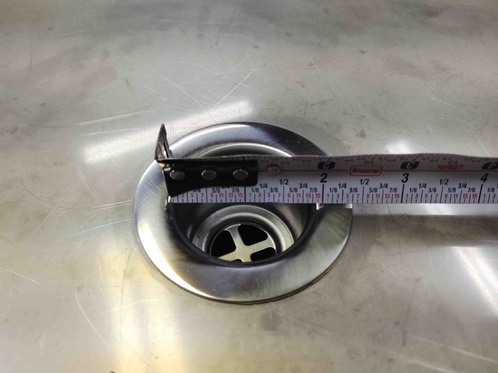
For comparison’s sake, the original drain hole was 1″ in diameter, with the actual drain 3/8″ in diameter. Here you can see my modified drain is just under 2″ in diameter, with a good 1″ diameter for the actual drain…. about as bit as the original total drain mounting hole diameter.
I’ll touch on this here although I discuss it in my videos on plasma cutting and the plasma cutting table…. I had originally decided to buy a Hypertherm 45XP plasma cutter and that decision had been solid since I pulled the trigger on the Crossfire Pro table in November.
However, as I started digging into the forum, I kept seeing the PrimeWeld Cut 60 plasma cutter popping up with rave reviews and glowing feedback from its owners. Ironically, after a lot of research I had already decided I was going to buy the PrimeWeld TIG225X ACDC welder and was merely waiting for them to come back in stock.
So, the more I researched the PrimeWeld Cut 60 plasma cutter, the more convinced I was that at 25% of the price of a Hypertherm 45XP (which is THE flagship for home and small business plasma cutters), I could buy a Cut 60 and have enough in my budget to buy a lot of extra goodies that would simply have to wait a considerable amount of time before purchasing if I went the 45XP route.
So although it might mean a bit more legwork on dialing the machine in for consistent use, I just couldn’t pass up such a seemingly overwhelmingly good cost-benefit ratio… Thus, I pulled the trigger on the PrimeWeld Cut 60.
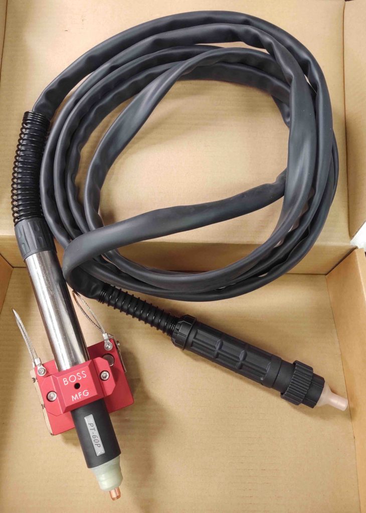
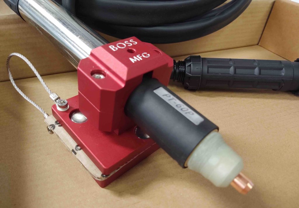
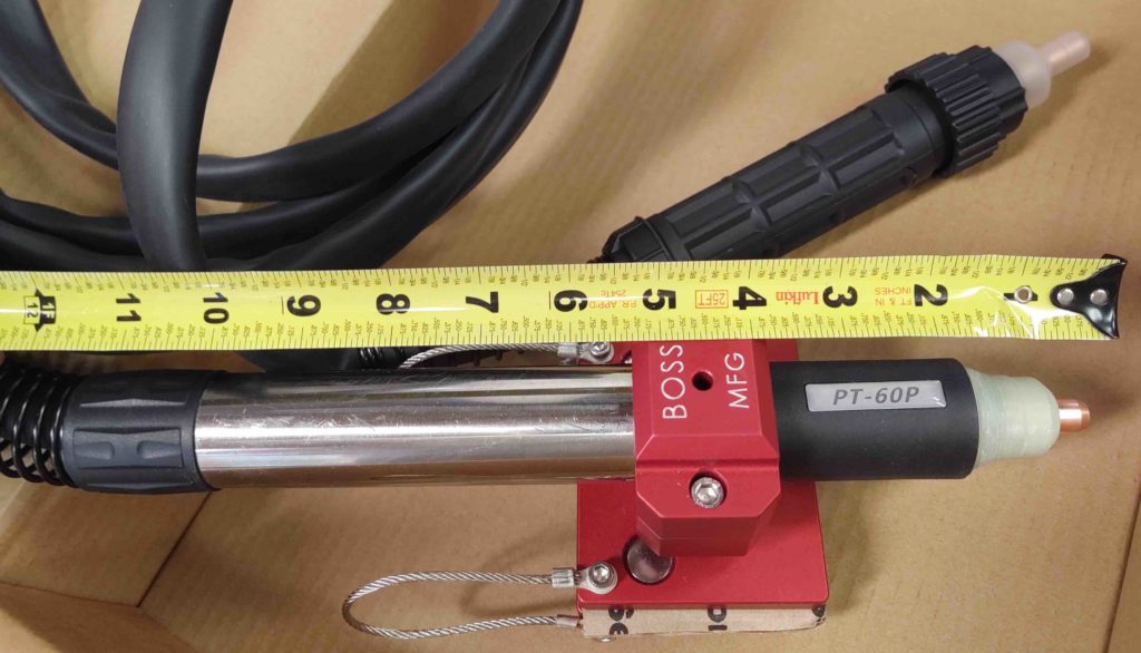
In the ensuing days, with the money saved on my PrimeWeld purchase, I then pulled the trigger on a machine torch (guarantees a much higher quality and infinitely more consistent cut quality) and a magnetic break-away torch mount (which pretty much guarantees NOT breaking your torch if it crashes into a “tip up” or other gnarly metal protrusion during cutting ops).
Another couple shots of the machine torch mounted in the magnetic break-away torch holder [note how tall the machine torch is…]
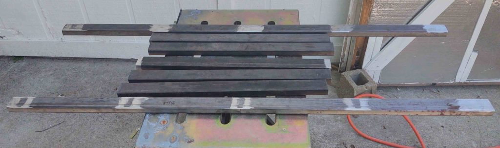
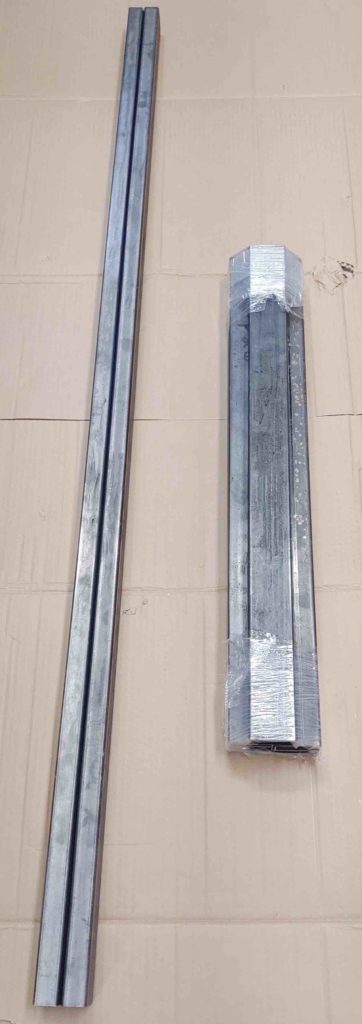
As I mentioned above, I discovered a common modification for the Crossfire Pro table was to add a lower shelf for both the plasma cutter and water table reservoir to be placed. After a bit of research, and copying a BOM placed on the forum, I placed an order for all the metal required for the lower shelf mod.
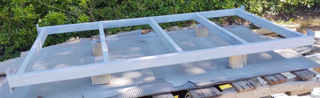
Below left is a general outline of the lower shelf frame. I chose 1″ x 2″ tubing, where I noted most guys opted for 2″ x 2″ tubing.
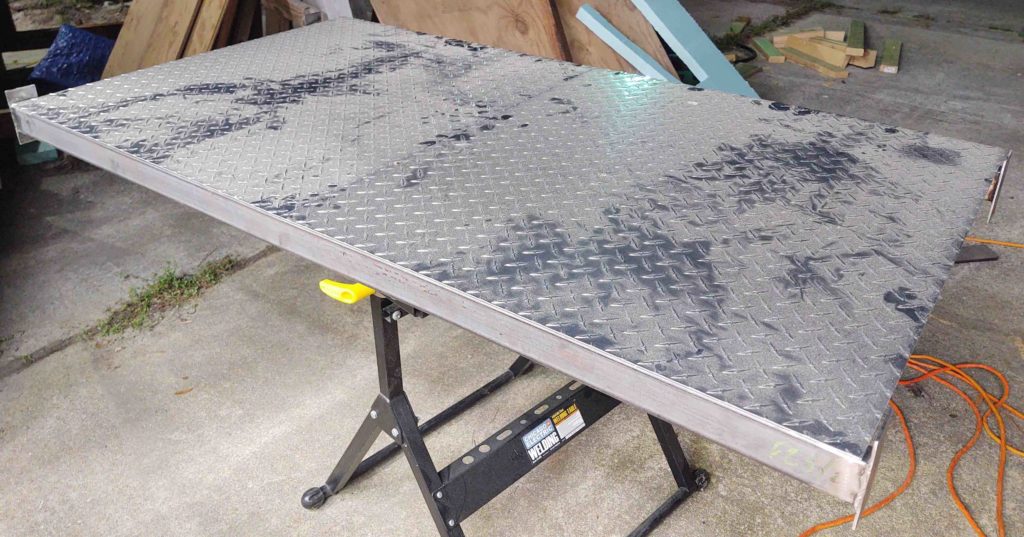
To the right is the aluminum diamond plate panels that I ordered –although a tad more expensive than flat panels– to spice up the top of the shelf a bit.
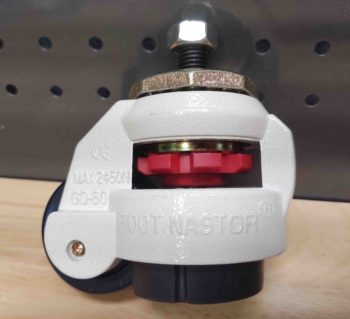
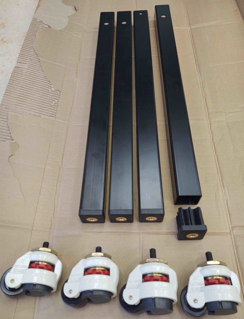
Another great tip I received on the forum was to replace the table’s stock leg foot pads for Foot Master casters, which serve as both solid foot pads and casters by manipulating the red rotating handle.
BTW, these are cheaper knockoffs that I got off of eBay only because the delivery dates on Amazon were all way too long. And that’s after my original order was canceled by Amazon as undeliverable.
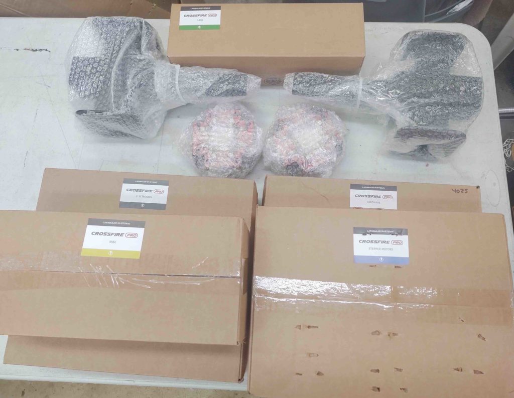
A couple of weeks after Box 3 (water table) arrived, I received Box 2, which is everything else for the entire plasma cutting table sans the frame tubing: hardware, cables, electronics box, gantry assemblies, bearing assemblies, stepper motors, miscellaneous, etc.
About a week after receiving Box 2, I spent a good 2 hours late one evening inventorying it and repackaging all the hardware into bags that matched the assembly steps in the manual. This greatly accelerated the assembly process as soon as Box 1 (frame tubes) arrived.
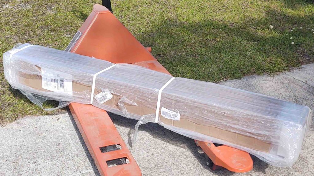
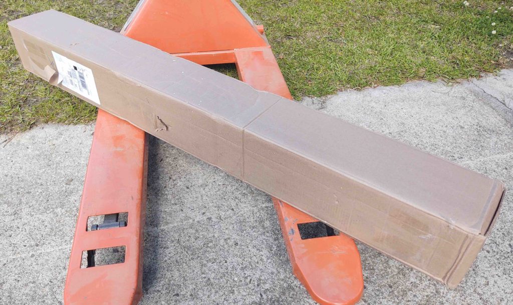
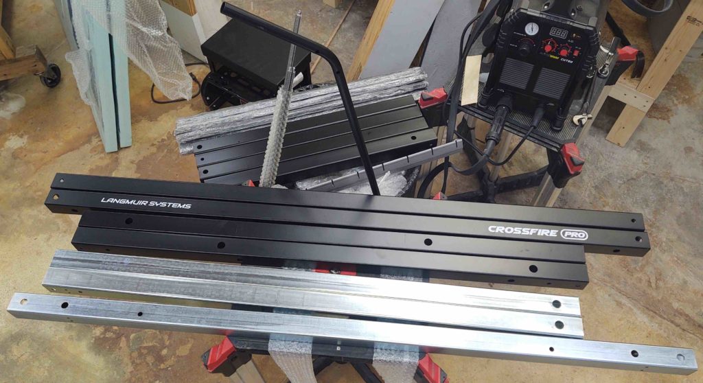
I should note that Box 1 not only contains the frame tubes for the table, but also the lead screws for the 2 Y-axis stepper motors and the X-axis stepper motor. Well, those happened to be the one thing that was delayed in production, so instead of getting all the orders out and delivered in April as had been quoted, all us Batch 2 bubbas received our Box 1’s in mid-May (13 May to be exact).
No big deal as it gave more time to get things prepared (and work on the shop!). Here’s a couple of pics of Box 1 literally moments after the UPS guy and I placed it onto my pallet dolly.
And not an hour later after I unpacked Box 1.
After waiting over 6 months to receive this thing, I then got to work assembling the plasma cutting table!
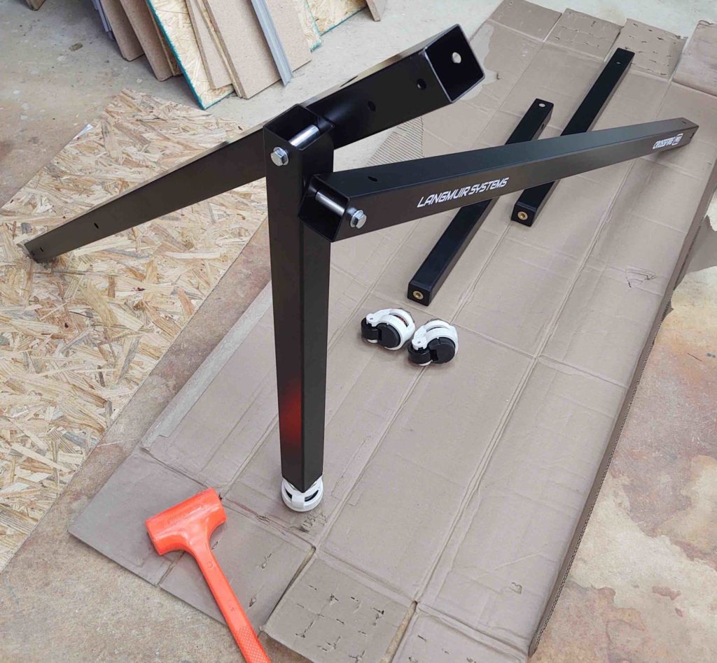
First off was the table leg caster mods. The black leg insert that the Foot Master caster mounts to was yet another component that was ID’d by part number (McMaster-Carr) from yet another forum member [I tell ya, that forum is pure GOLD!].
I then started assembling the table . . .
The assembled table frame shot below left may look innocuous, but it took well over 2 hours to get the table corners square and the 2 respective table end tubes (that the Y-axis gantry tubes attach to) parallel to within 0.030″.
I then attached the Y-axes tubes and the bearing assemblies that mount to the x-axis gantry cross tube.
Here we have both the Y-axes and X-axis gantry installed. Note also that the Z-axis and torch mount are also assembled.
I then set the water table in place and spent another 30 minutes ensuring that it was exactly equidistant to the sides in all directions.
It was late so I left the super noisy job of driving self-drilling screws into the table frame until the next morning.
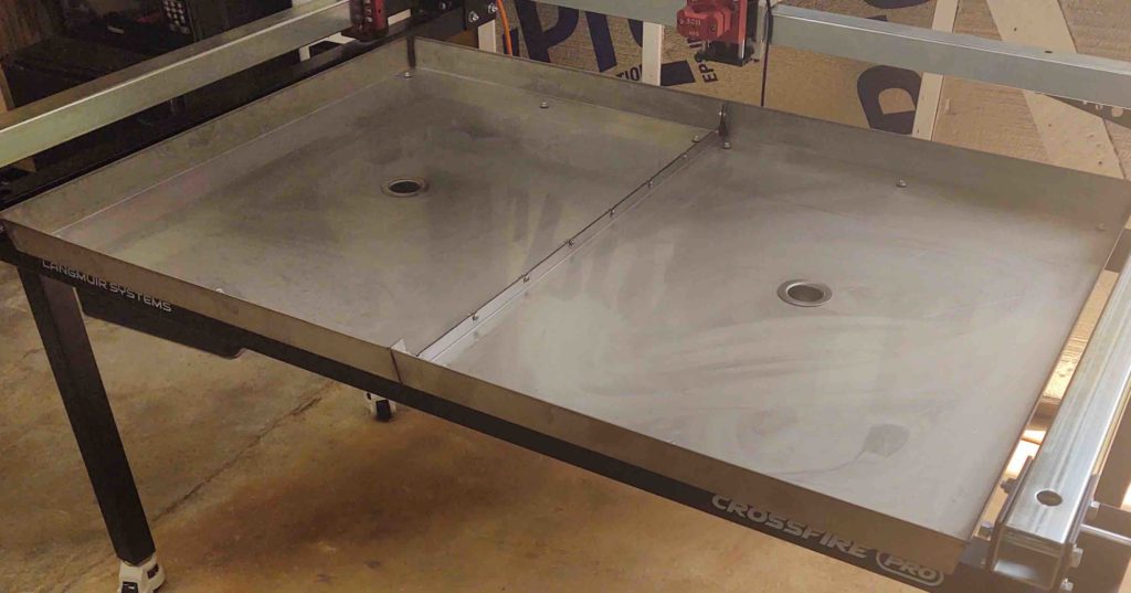
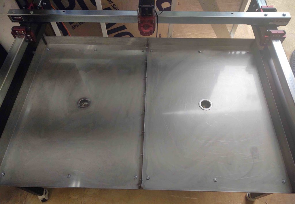
Here’s the water table after it was attached with self-tapping screws into the table frame cross tubes.
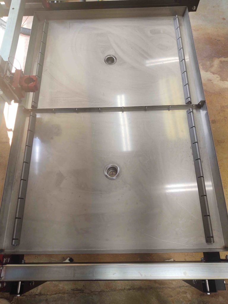
I then set the triangular slat holders in place.
And mounted the water table slats into place.
Next came wiring up both the Z-axis stepper motor cable and the Initial Height Sensing cable, both of which require routing to the electronics control box via the cable (aka “fishing”) pole.
Also note that I installed the lower table frame gussets and end aprons to lock the squareness of the table into place.
Finally, in the lower back left corner you can see the electronics box has been mounted to the table leg.
And with that, the plasma cutting table is officially operational!
But wait! There’s more…. tomorrow I’ll start work in earnest to weld up and paint the lower shelf, which will enable me to actual use this table (since I already swapped out the stock water table drains for the new ones…. which now require a water reservoir and plumbing).
I finally got around to listing the ton of unpacked, broken down boxes I had on hand from moving on Craigslist and a local neighborhood billboard. I hate just recycling those things if someone can make use of them. Well, as it turns out four separate people ended up grabbing what they needed and polished off my stock of moving boxes.
It’s the little things . . .
With the garage a lot less filled I was able to assess its configuration better and had a bit of a mini-epiphany regarding installing a workbench along the back wall. You see, I still had a fair amount of wood left in the pile in the workshop…. again, from having built those temp walls to remove the middle pillar and add a long set of beams.
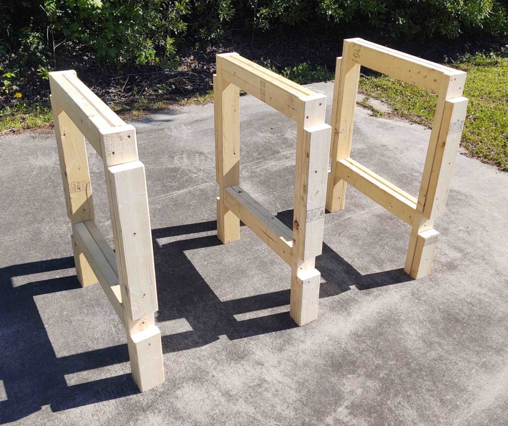
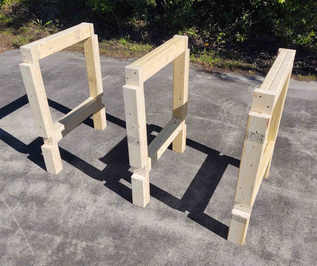
Moreover, I had 4 double-2×4 boards leftover from the beam project. With that many nails holding them together it’s a real pain and time bust to separate the boards. Using them up, as I did below, in creating end and middle uprights for a new table wiped out the stock of doubled-up 2×4 boards. Nice to find a good purpose for those things!
I of course used up even more of the 2x4s on this garage workbench, reducing the number of boards in the workshop even more. A real win-win.
Does this garage workbench relate to building the airplane? In a way it really does support the effort since in my ability to get the garage more organized, and gain access to previous hard to reach areas, I was able to extract a lot of tools, equipment and parts for the the airplane build.
And as I said in a very recent post, I also avoided unnecessary hauling of lumber just to stack it somewhere else to then build from that stash later on.
I cobbled together a couple of long strips of OSB for the bottom shelf . . .
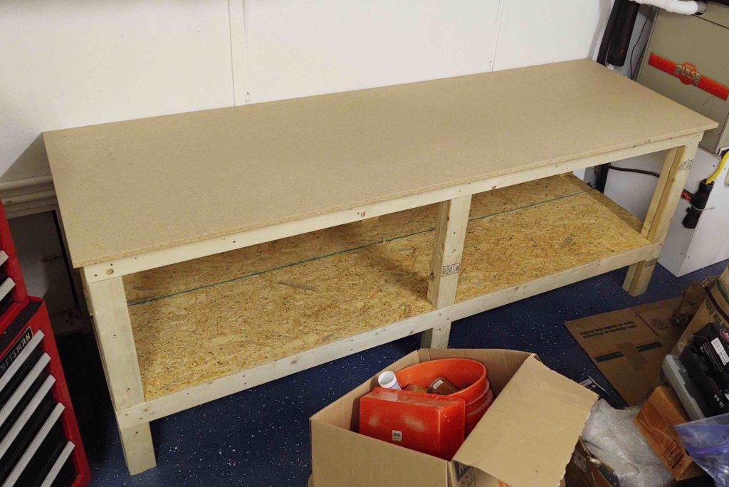
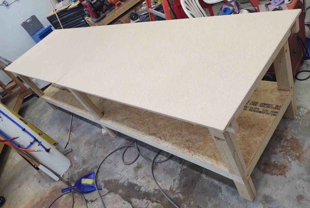
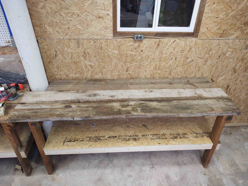
And then went cheap again with a new, fresh piece of particle board for the top. The measurement for this table is 8 ft wide x 31″ deep.
As I alluded to above, after I finished the workbench above I spent well over 3 hours organizing the garage and hauling A LOT of airplane-building related stuff back to the shop.
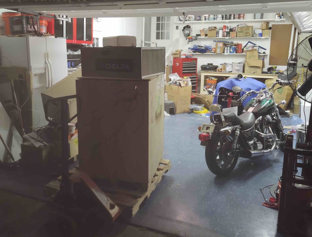
In fact, the biggest haul of the night was the milling machine, which hasn’t moved from it’s spot in the garage since I received it back in Sep 2019. Well, the time had come for it to make it that last 50 yards to it’s final home in the workshop.
Needless to say, this thing is heavy! But after slogging through to get it across over 20 yards of no-man’s land that is the grass and pea-gravel stretch of driveway (almost half of the total travel distance) between the garage and workshop, it was finally in the workshop near it’s final mounting spot.
Over the next few weeks or so, as I’m finalizing the walls and outfitting the workshop, I’ll get the mill tore down, cleaned, modded a bit, reassembled and then ready for action.
I’ve been getting a lot of the tools, equipment and parts moved out to the workshop as I’m finishing up some of the finer details of the shop. And I will be getting back on the walls to finish those up within the next few days.
Yes, it’s been a week since my last post . . . time flies.
We’ve still been getting a good bit of rain showers on and off over the past week. A good day and a half of rain actually didn’t matter at the end of last week since I killed a good 2 and a half days on getting my taxes sorted out and filed.
Although I have one large wall section and the final big door section yet to complete, both located in the front left corner of the shop (viewpoint from looking at shop from outside front), I’m also in a bit of tying-up-loose-ends phase on the shop prep.
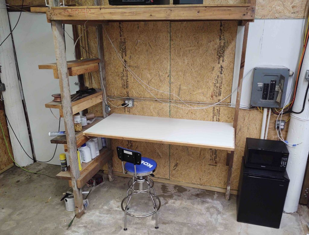
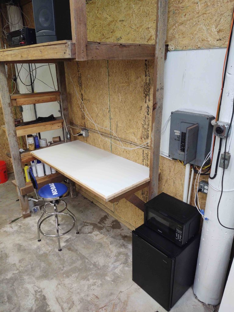
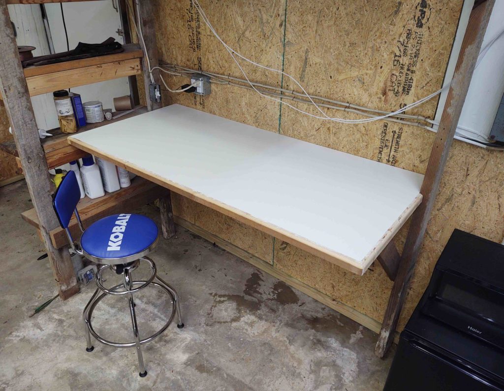
For example, not only did I get the kiosk desktop installed, with edge trim sanded, but also installed a switched light as well. This was part of large effort to finish up the electrical in the workshop. The majority of that just entailed merely reinstalling the electrical lines I took down to finish the walls.
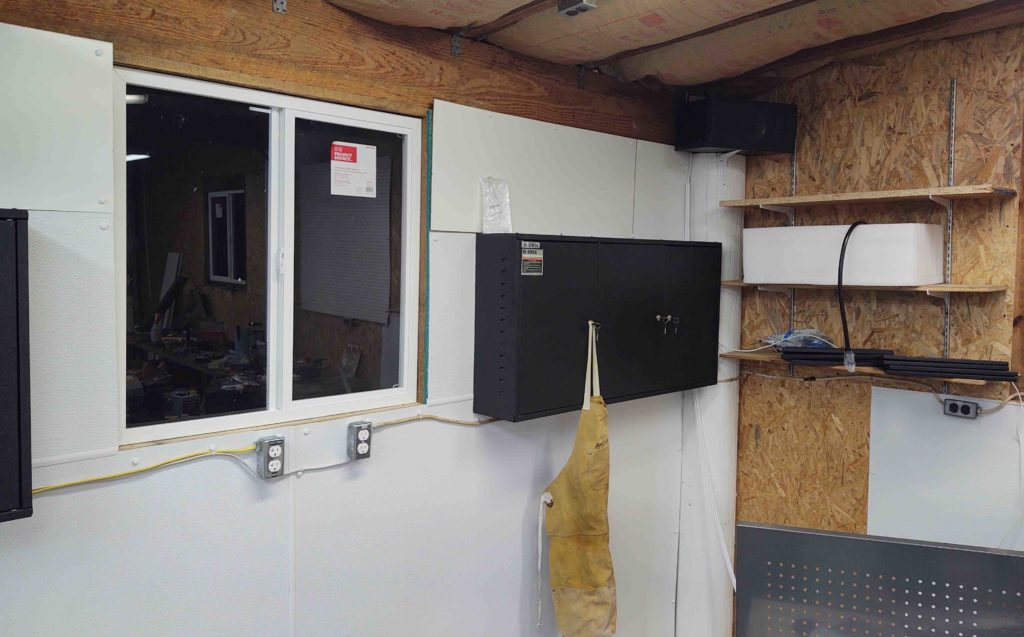
I finished replacing the circuit that starts at the front wall and ends at the back wall. Next to the 120V line (right plug beneath window) is the 240V circuit for the milling machine. [Also note I cut the remaining white 1/4″ paneling I had on hand and mounted above the cabinets].
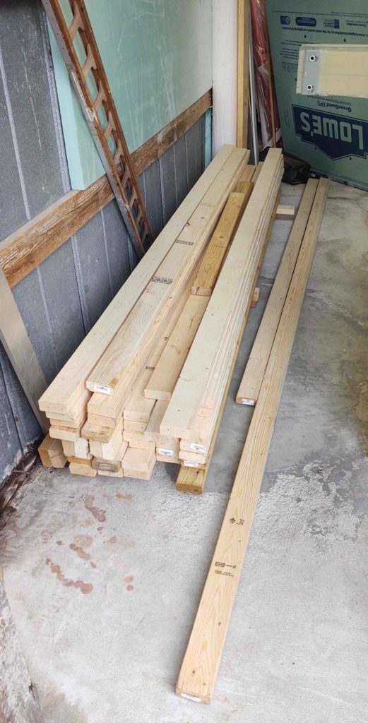
To tackle the remaining big section of wall I first need to move a big pile of 2x4s… that I stacked up after tearing down the temp walls I built to hold the roof up during my big beam install and center roof support post removal.
Although it results in a delay on getting the wall section completed, instead of messing around with the wood twice I will simply use all of it I can before moving the remainder of the pile. Hmmm, efficient or lazy?!
Part of the shop upgrade plan has always been a big worktable ala Chapter 3 of the Long-EZ build plans. So to kill the proverbial two birds with one stone I started the big table build from this pile of 2x4s.
To be even more la… er, efficient, I decided to use plans from a workshop table that I’m quite familiar with: my buddy Marco’s. Knowing that he documented and detailed his table build on his blog, I simply based this work table almost entirely off his design (Thanks Bro!).
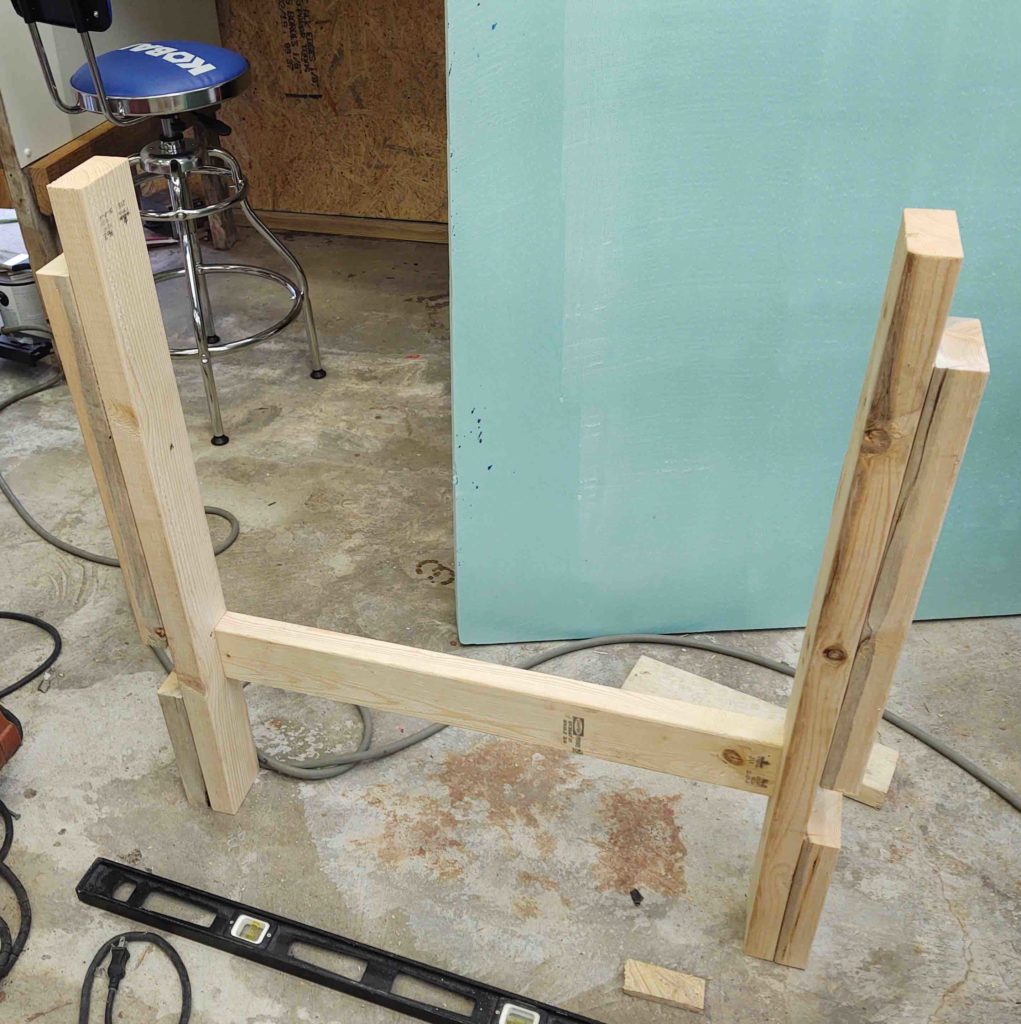
Starting on the big workbench build, I’ll point out that a number of the 2x4s in my pile were actually double boards that I had nailed up and down the length of the boards for strength… again, during the big shop center beam install. Separating these paired-up boards would be quite the pain, so I used those first for the 6 work table legs since they needed doubled up 2x4s anyway.
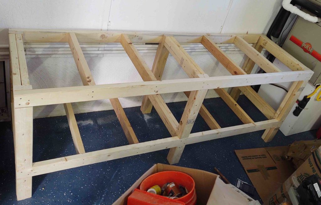
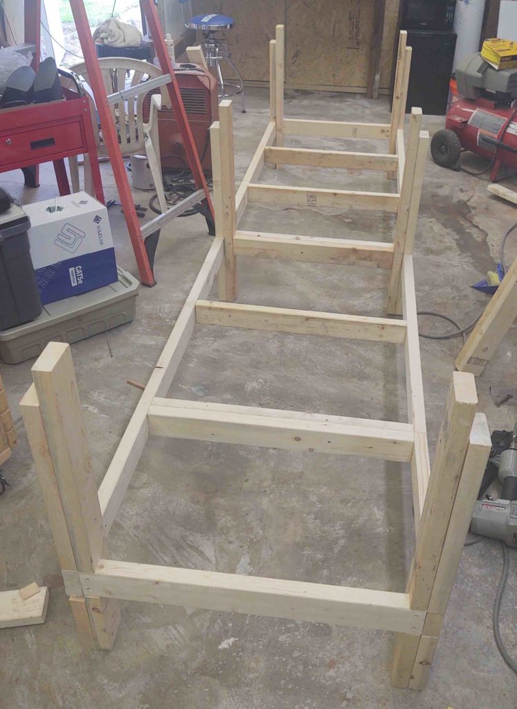
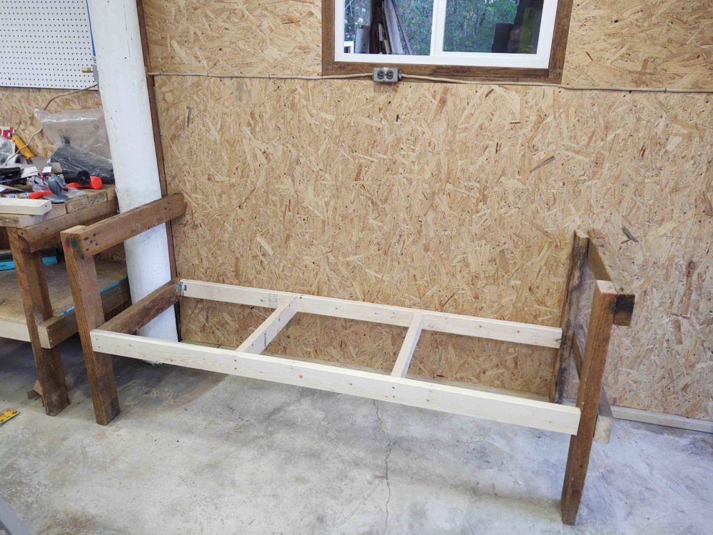
Here’s the basic frame of the 12′ long shop work table. The bottom shelf is 34″ wide while the table top is 39″ wide.
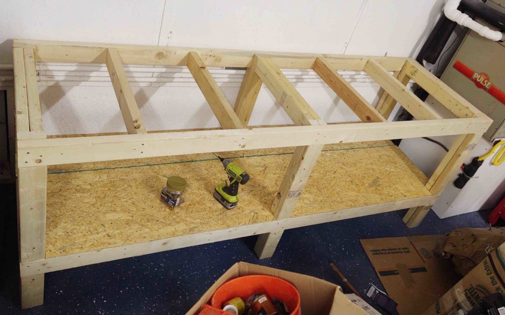
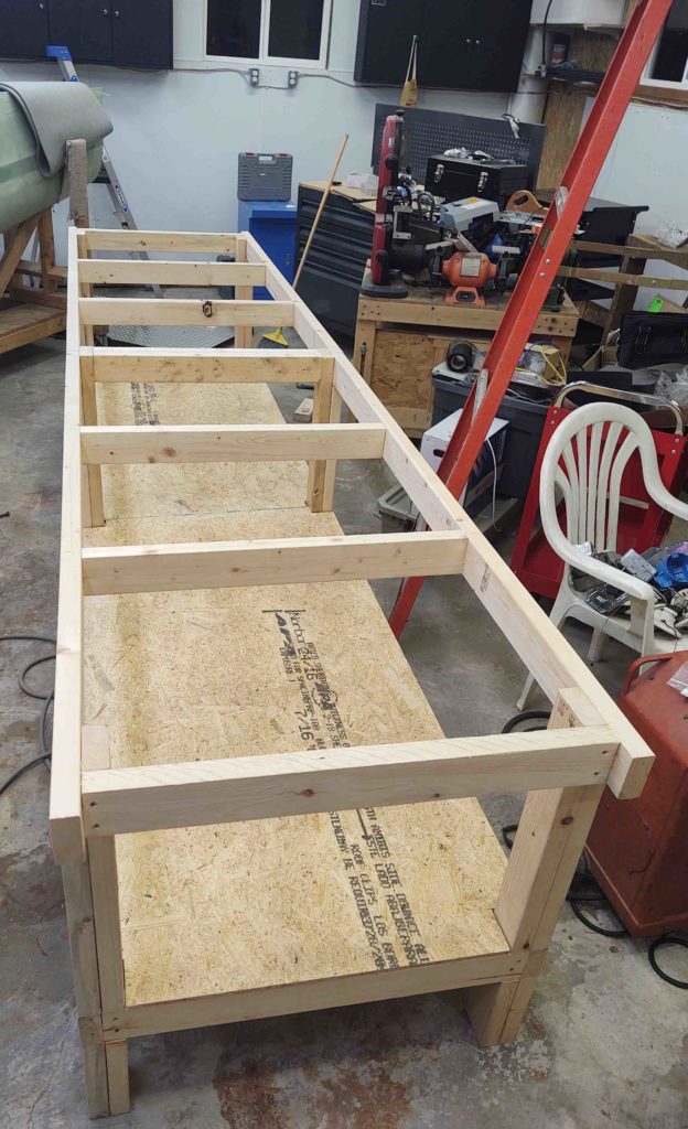
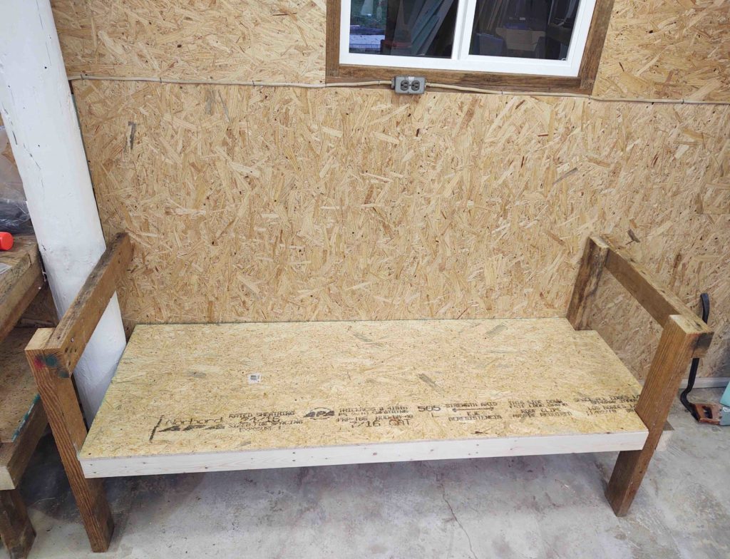
Day 2 of the table build —after a trip to Lowe’s for materials— I cut and installed the lower shelf sheets of 7/16″ OSB.
The entire frame of the shelf was built from the 2x4s I had on hand in that pile, and all I needed from Lowe’s was the bottom shelf material and the table top material: 3/4″ particle board. I had planned on going with plywood for the top, but at twice the cost it just wasn’t worth it since particle board will more than do the job here.
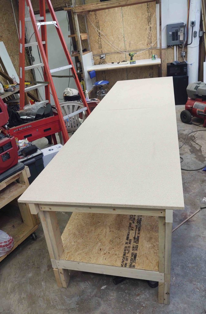
I already had the 2x4s on hand for the beam project (which I had planned on re-using for this table project, specifically) so I didn’t count them in the cost of this table build, which was about $50 total. Add around $25 for the 2x4s for a true total cost.
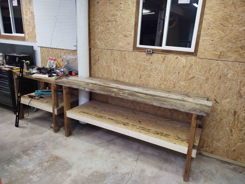
It took me a while to determine the actual length, width and location of the table, but I have to say I’m really pleased with the outcome.
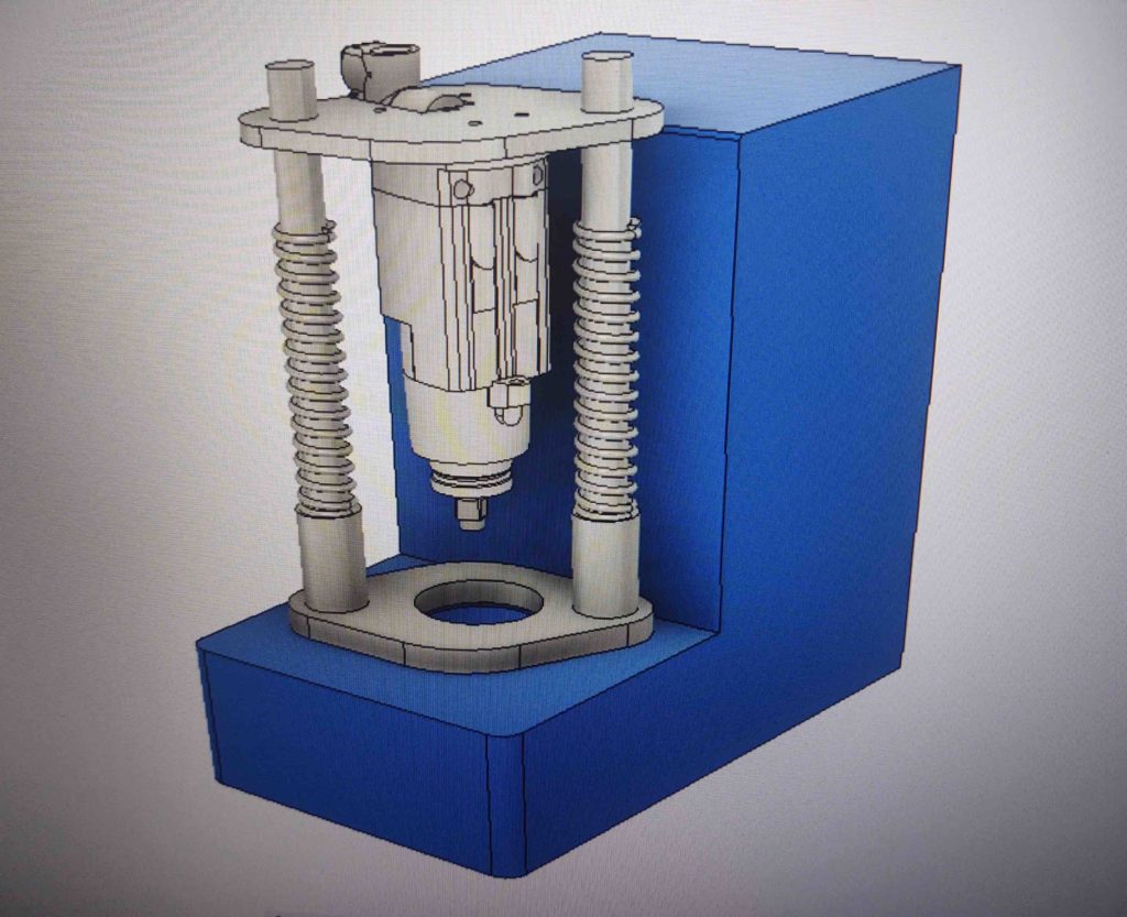
In addition, I thought I’d show you what I’m working on late at night before I hit the rack: this is the new version of my Milling Machine’s power drawbar. The blue box looking thing is the motor housing off the mill, and the light gray contraption is the drawbar assembly that I’ll build to mount the pneumatic wrench, which is in the middle hanging down from the top plate.
My next task will be to finish up insulating the wall and double doors on the front of the shop. Then build the hanging shelf over the double doors to finish up using as much wood from the 2×4 pile as possible before hauling the remainder out to under the carport.
This blog post is a multi-day wrap-up on my Workshop Admin Kiosk desktop build (yes, I make up eccentric names for stuff out of boredom!).
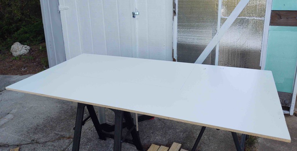
I started off with a quite heavy 4′ x 8′ sheet of Melamine for the desktop. The desktop will measure about 65″ wide by the proverbial 30″ deep. They don’t sell any smaller Melamine pieces large enough to meet these dimensions, and plywood is just as expensive… and softer. So I picked up this beast.
[Note the blue-green foam on the doors. Within the next day or so all that should be covered with the thinner foil looking foam]
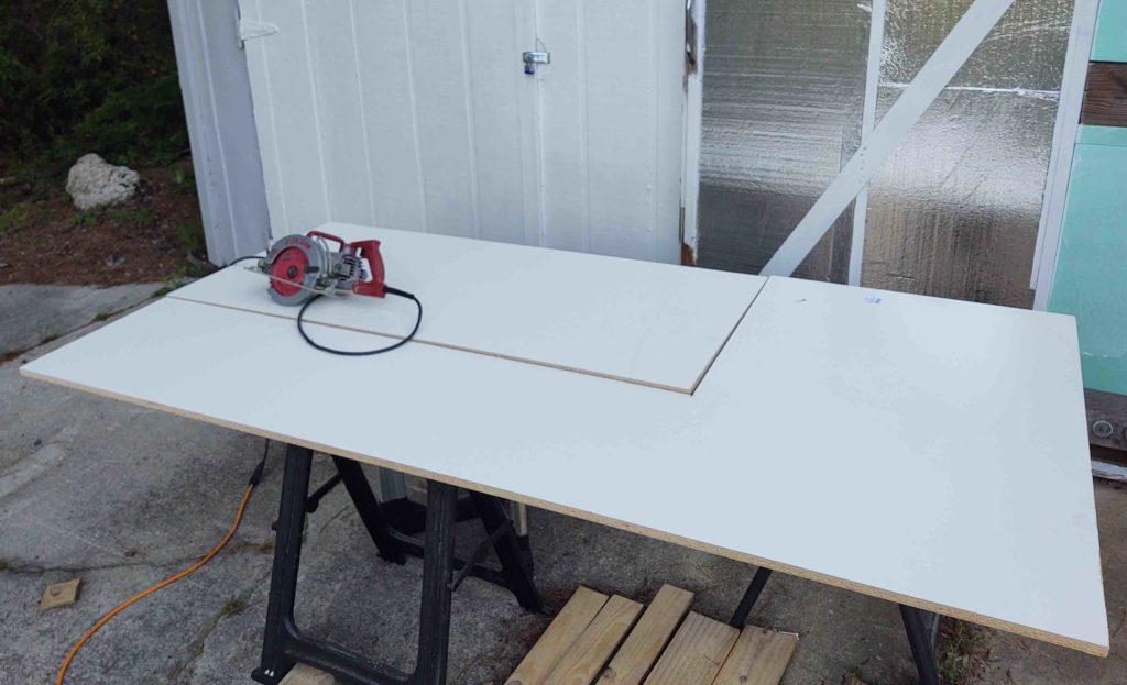
I measured and marked my 65-1/8″ x 30″ and cut away, testing my ability to follow a line… note my 2 cut lines are along the back and side that are not that critical. Mama didn’t raise no dummy. Ha!
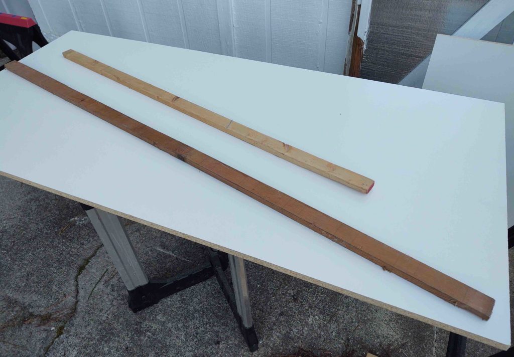
If you saw how much wood I have on hand, the few prospects for decent trim wood is laughable. The darker 1×2 was some misused (I’m sure…) piece that existed in the workshop when I arrived. The lighter piece? Dunnage from an Aircraft Spruce shipment.
Moving on… the ACS piece was narrower than the other, and oh, crowned as well. So a few rounds on the table saw got them both within acceptable close widths. Or actually heights.
I then mitered the corners. Both ends for the long piece since it came up a couple inches short so I borrowed a short cutoff length from the ACS stock.
After a quick –albeit comical– round on the router table I got some acceptable rounded corners [I wanted a smooth rounded edge, but in my haste left a fancy edge with a minute square edge on the first piece… did the second one to match. Ugh.].
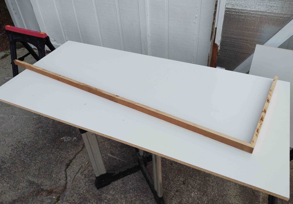
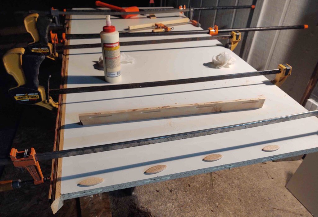
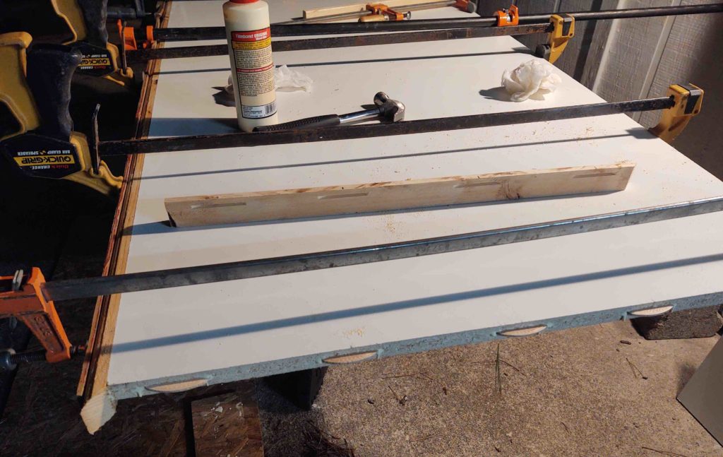
I then grabbed a tube of biscuits and my biscuit joiner and made quick work of getting my football (American!) shaped holes ready for some major gluing action.
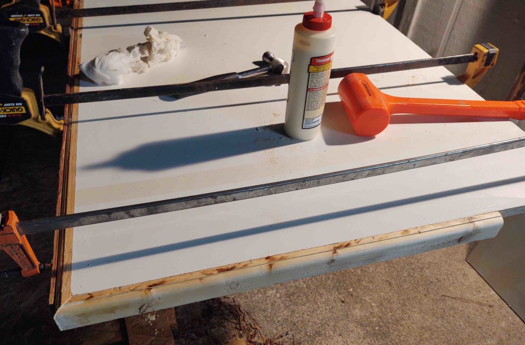
Since I didn’t have long enough clamps to go from one end to the other, I did the short side piece last and then . . .
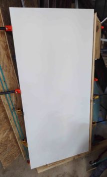
simply set the desktop up on end on top of the biscuit-glued side edge and let it cure overnight.
Since the weather was dryer, I did a good round of painting (in pic below: remaining spots on the left and right showing poles, as well as the area around the breaker panel).
Yes, the area around the circuit panel was cosmetic and took all of 10 min. As a reminder I’m painting the poles to get rid of every last remnant of tar/pitch smell… which was super strong when I first bought the house. Now? You can barely smell it. But leaving areas unpainted definitely lets the odor hang around a bit. Understandably, it’s worse in really hot weather.
I grabbed the blue Kobalt stool (and assembled it) from Lowe’s yesterday so I’d have a good reference for the height I needed to build the desktop support structure, which I completed this evening.
Besides painting, I also did a fair bit of electrical. You can see I swapped out the 1-gang receptacle above the desk to a 2-gang (4 plugs) and also pigtailed power to a light switch that will power a 48″ 1-bar light under the overhang for good lighting in the Admin Kiosk.
In addition, I added a 15A circuit to the power panel (the last available slot) to add a 2-gang box just below the power panel. This powers the mini-fridge and microwave. Coming soon on top of the microwave will be a Kurig for the COFFEE!
I also RE-connected an electrical line extension on the back side of the right wall near the lathe. I had removed an electrical outlet with both plugs filled with what looked like solid mud that was totally inop. I have since replaced that plug and, again, rejoined the line that continues on to the back wall, ending with a 1-gang plug just below the window (behind where the milling machine will be located).
Tomorrow I’ll spend a good hour finishing up the power receptacle mounting at the back of the shop for both 120 and 240 volt power (240 for the mill).
I will then do a quick sanding on the desktop edge before mounting it permanently in place.
I will then turn my sights on finishing up the top foam inserts for the middle double doors before moving on to the last front section of wall left to do on the shop (#9 of 10 wall segment).
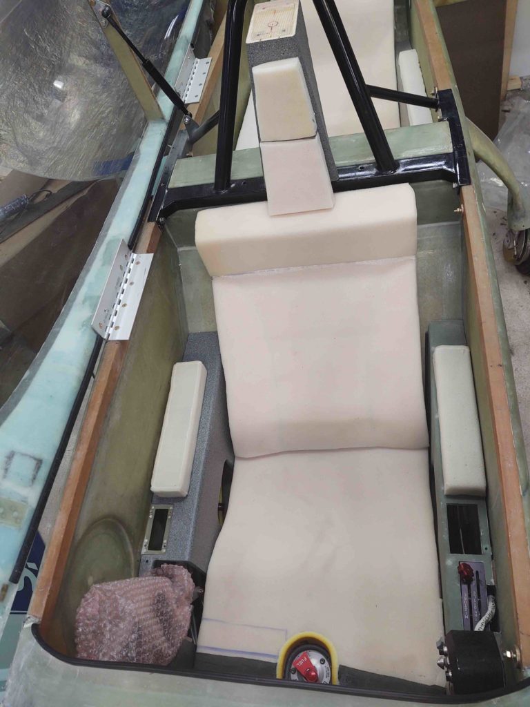
Today I got the seat cores back from Oregon Aero, which was a bit of a surprise since I knew they were on their way, but they arrived a couple days earlier than the tracking originally stated.
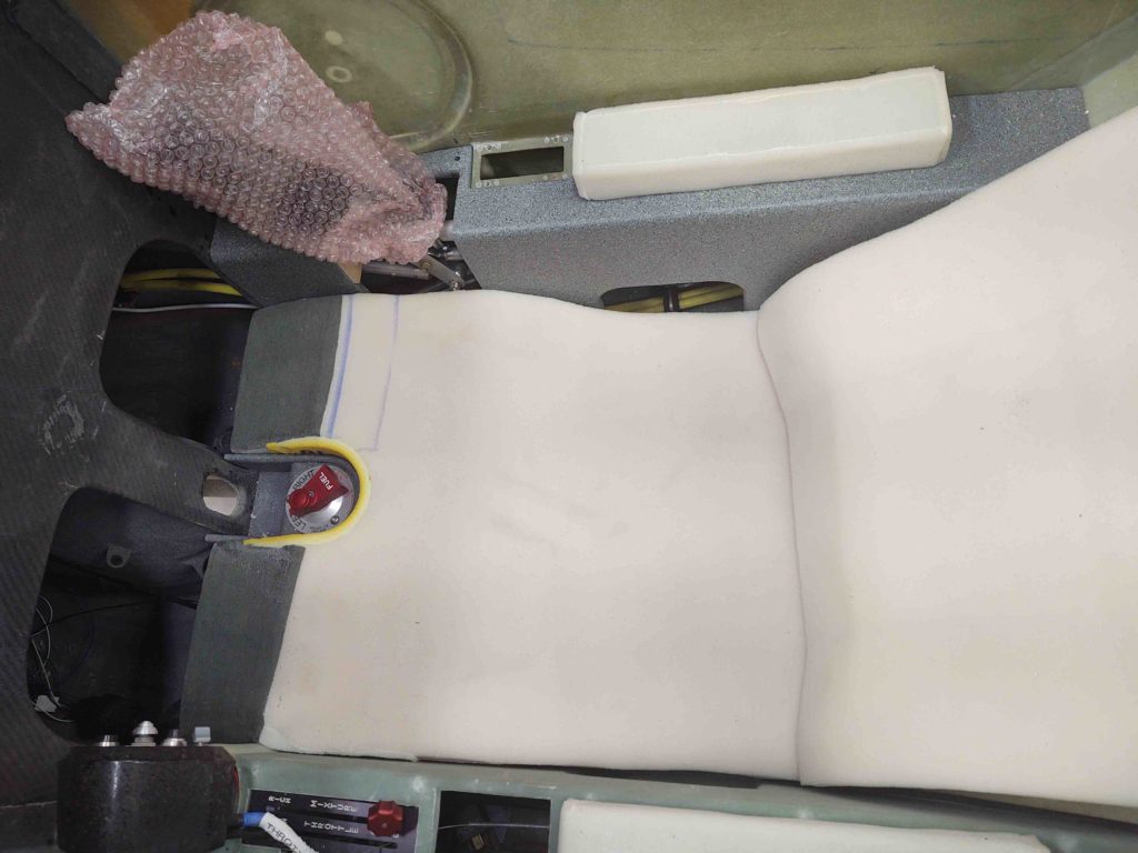
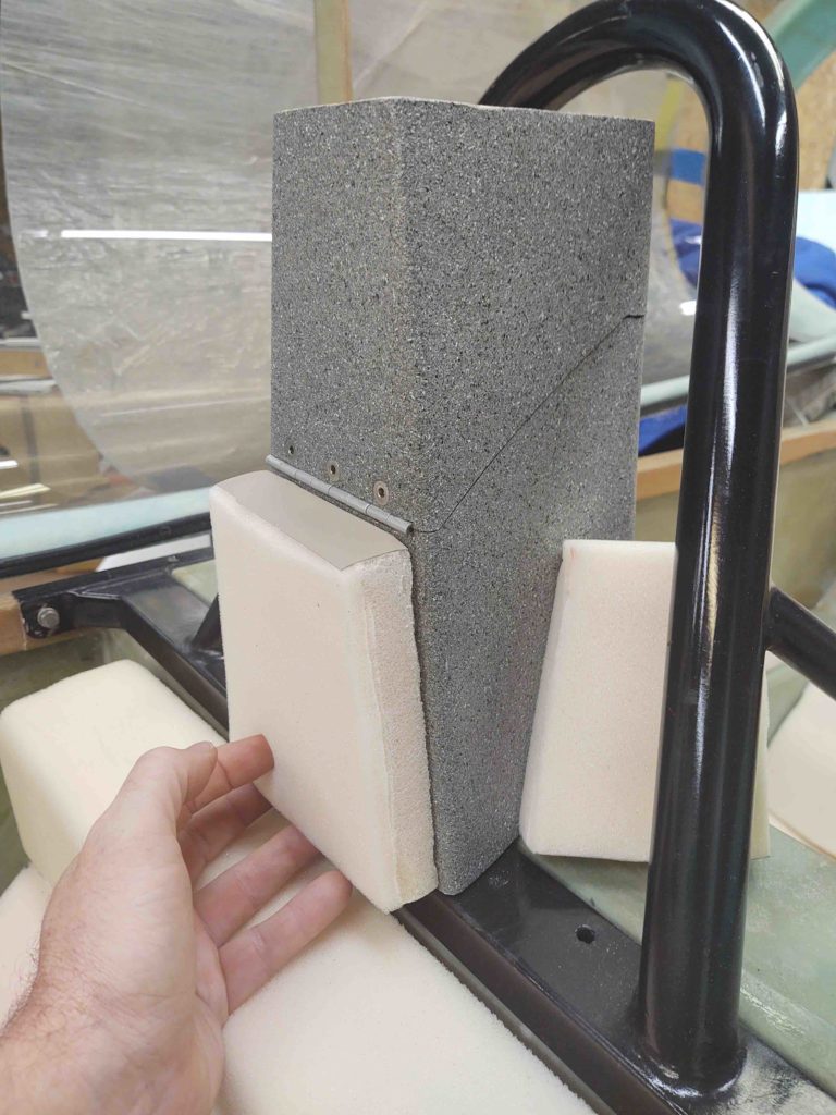
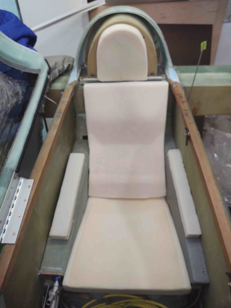
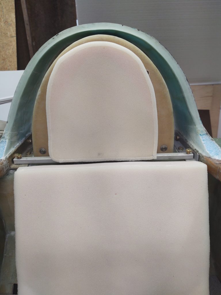
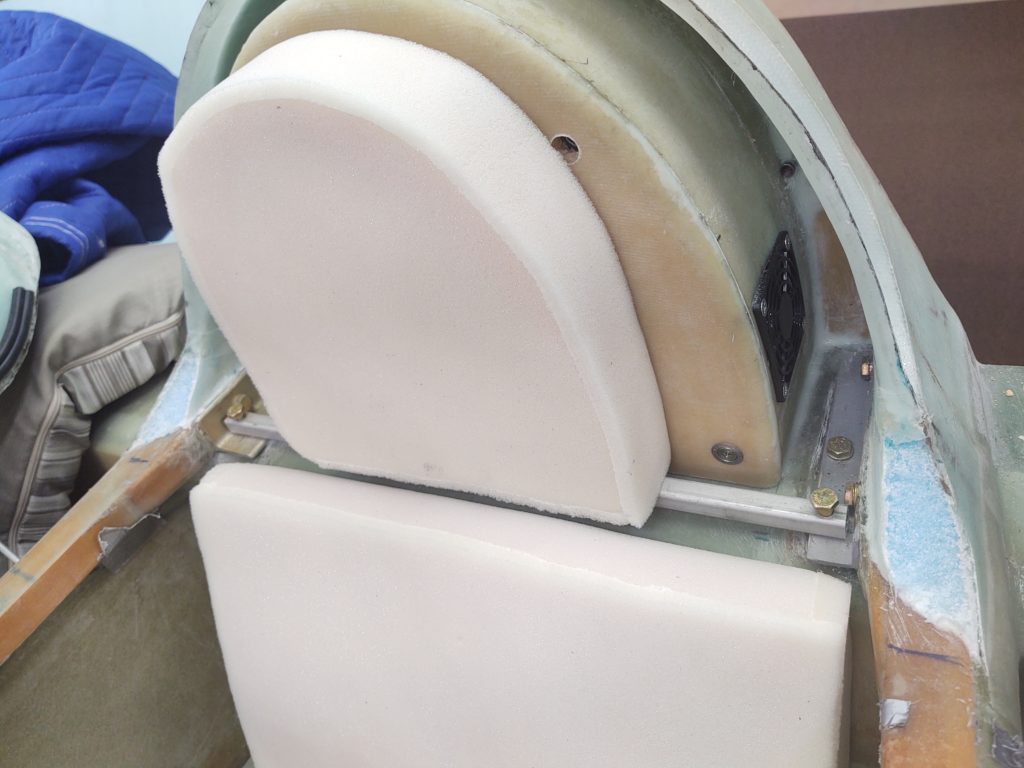
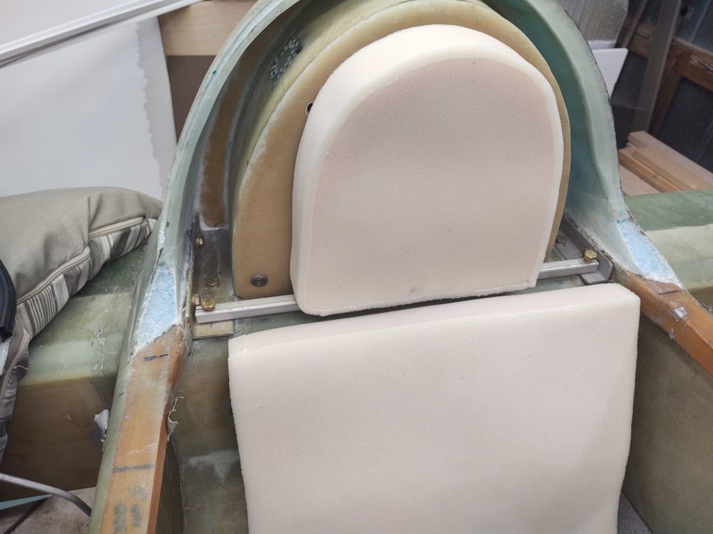
The seat cores 2.0 are a HUGE improvement over the initial versions. All the cushions fit MUCH better —darn near final state— and even the look of them in place is vastly improved.
Alice and Lisa at Oregon Aero worked every tweak I asked them to… here the thinned and “ridgidized” front seat leading edge, the back filled area (yellow) around the fuel selector valve, and simply eliminating the small indentation we were trying to create to allow for the cup holder (not needed).
The front seat upper cushion actually makes visual sense now and looks 10x better as well. It follows the angles of the front seat bulkhead and looks like it belongs. Huge, huge improvement.
Grant it, these are my initial visual observations of course. I will definitely need to do an extended butt-in-seat test again to assess the new mods.
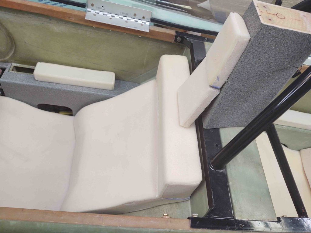
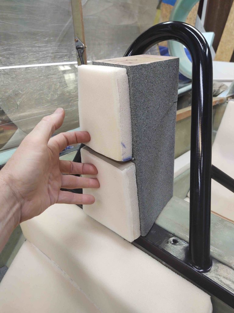
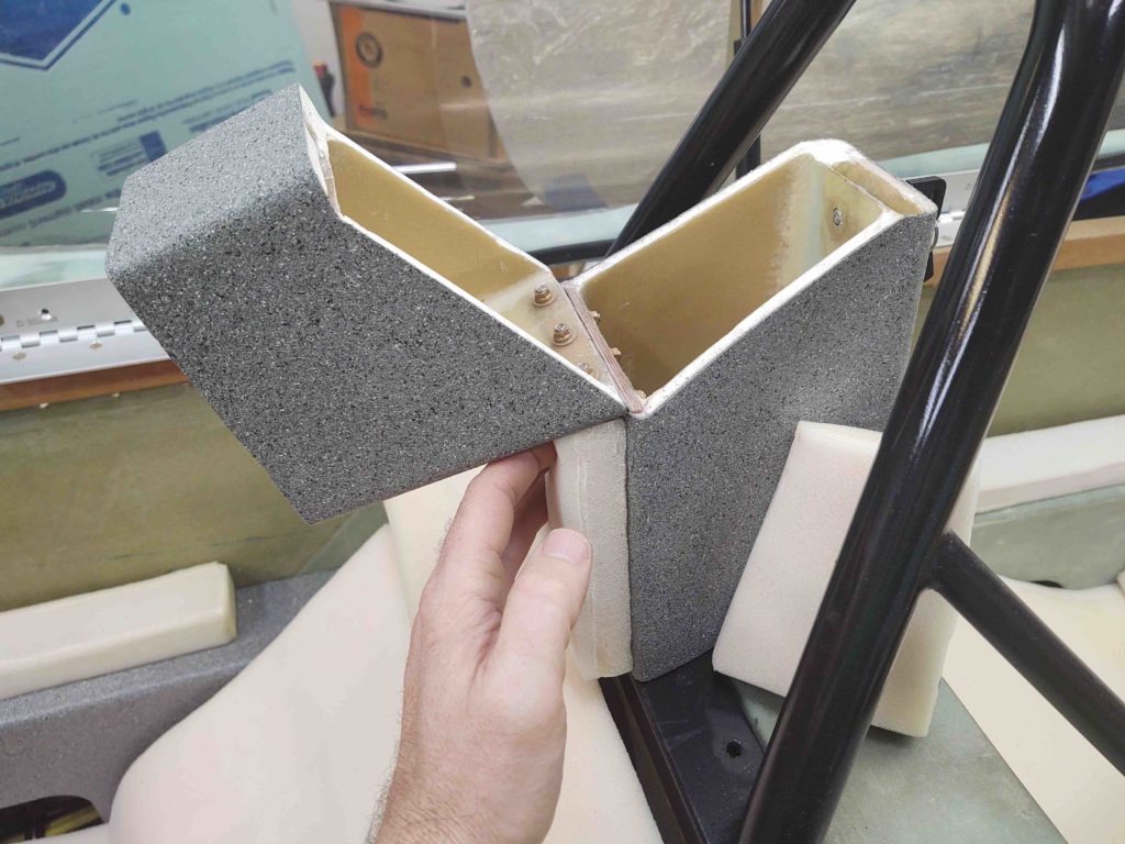
I have to say, my biggest disappointment is the front seat headrest. They thinned it down by a good inch like I asked, and also lopped it in two horizontally at about the midway point, but it’s a mess as far as having any faint semblance of symmetry. It’s just all wonky! Luckily it’s a small piece and should be a quick fix.
Not to be negative, because I am really happy with the results of this last round of tweaks… but I can see that the angle of the uppermost front seat top will have to be tweaked so that the top back edge is reset about 1/2″ aft of where it is now.
That being said, it just all looks SO much better than it did before!
I had them split the pilot’s headrest pad for practical reasons when on the ground. I think this headrest pad will provide me just as much comfort –when I use it– as would one that’s a solid piece.
I plan to mount the lower headrest pad so that it’s fixed in place pretty much permanently. The upper headrest pad will most likely just be velcro’d in place to allow for easy removal.
This configuration will allow me access into the headrest storage without having to remove the entire headrest pad (as before) and, moreover, it gives me a padded stop for the upper part of the headrest to rest on when open.
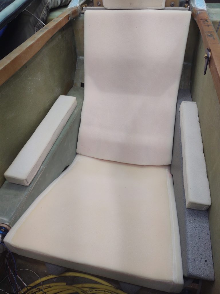
Ok, so where the front seat improvements were definitely significant, the back seat updates are night-n-day from the state these cores were in before.
The lower seat cushion is significantly wider and fills in the area between the two armrests very nicely now sans the huge gaps on each side that were present before. The added padding material is even visible along each edge.
The freshly tweaked back seat upper cushion is a phenomenal improvement over the first one. It’s significantly wider, which hides the spar storage access opening, and the height is perfect now. Previously it was so short on the top side that the cushion simply fell into the spar storage opening.
I’m very pleased with the job Oregon Aero did on both front and back upper seat cushions. They really made these seat cores look like the custom fit cores that they are!
I also had Alice & Lisa tweak the back seat headrest as well from it’s prior distinct flat spots and angles to a simple curved shaped.
BTW, any slight misshapes or minor alignment issues typically get wrangled in when these cores are crammed into their respective upholstered covers.
Here we have another couple shots of the back seat headrest and the top portion of the back seat upper cushion. Note the height of the back seat cushion… they nailed it!
In the next few days I’ll try to get my keister back in the saddle for a good hour to test fit these cores out.
Now I just have to decide the color(s) for my upholstery!
. . . and of course get the shop in shape for building.
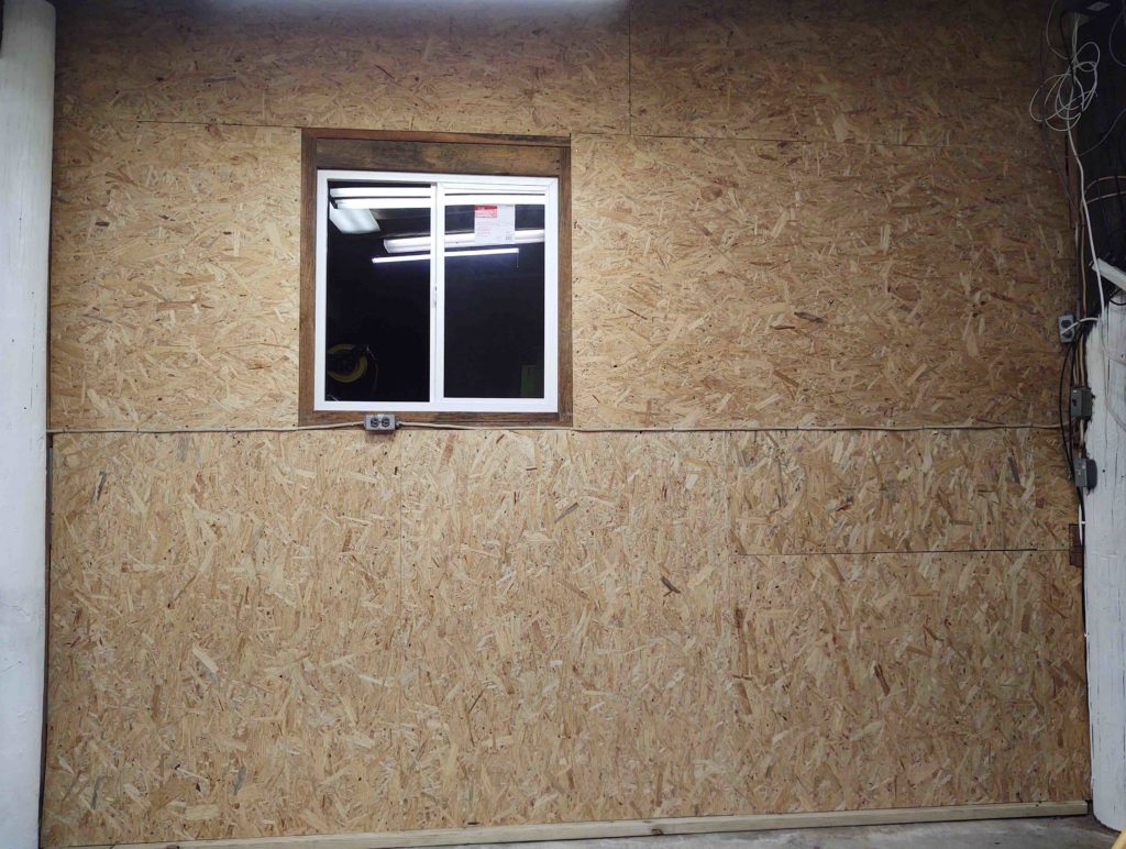
Tonight I finished the 8th wall section out of 10 for the workshop.
I had of course been working on this over the past few days, and finished up the insulating part by midday.
As is quite often the case, I needed more supplies so I made a trip to Lowe’s.
Upon returning I finished paneling the wall with OSB that I just bought.
Tomorrow I’ll work on finish re-securing all the power cables, cutting and building the admin kiosk desktop, and finally finish insulating the middle double doors (to the right of this pic).
The efforts on the shop continue… to borrow a term my Long-EZ building buddy Dave Berenholtz used recently, this pre-plane-building project of getting the shop in shape with the requisite myriad of tasks feels like a form of death by a thousand paper cuts.
But I have turned a corner –literally– and am on the front wall of the shop. Yes, there have been some delays, some self-induced with household/life chores that really needed tending to, but mostly due to spring rainstorms.
Yesterday I insulated nearly the last of the shop ceiling along the finished right hand wall, leaving about a 1 ft x 14 ft strip left to do at the top of the front far left wall.
I wanted to get the shop entry door insulated along with the rest of the walls but couldn’t find the required 1.5″ thick foam. What I did find was 3/4″ thick foam so I ended up doing a double cut for the 3 panels that existed on the door. This added a bit to the time, but I got ‘er done.
I then covered the door insulation with 1/4″ white paneling since I had an extra panel on hand that didn’t get used in the “machining corner.” I also added a handle to aid in closing the door from the inside.
I then moved on to the next section of wall that surrounds the entry door. From the outside this is the front right third of the shop. The only section on the front of the shop that does not have big barn doors.
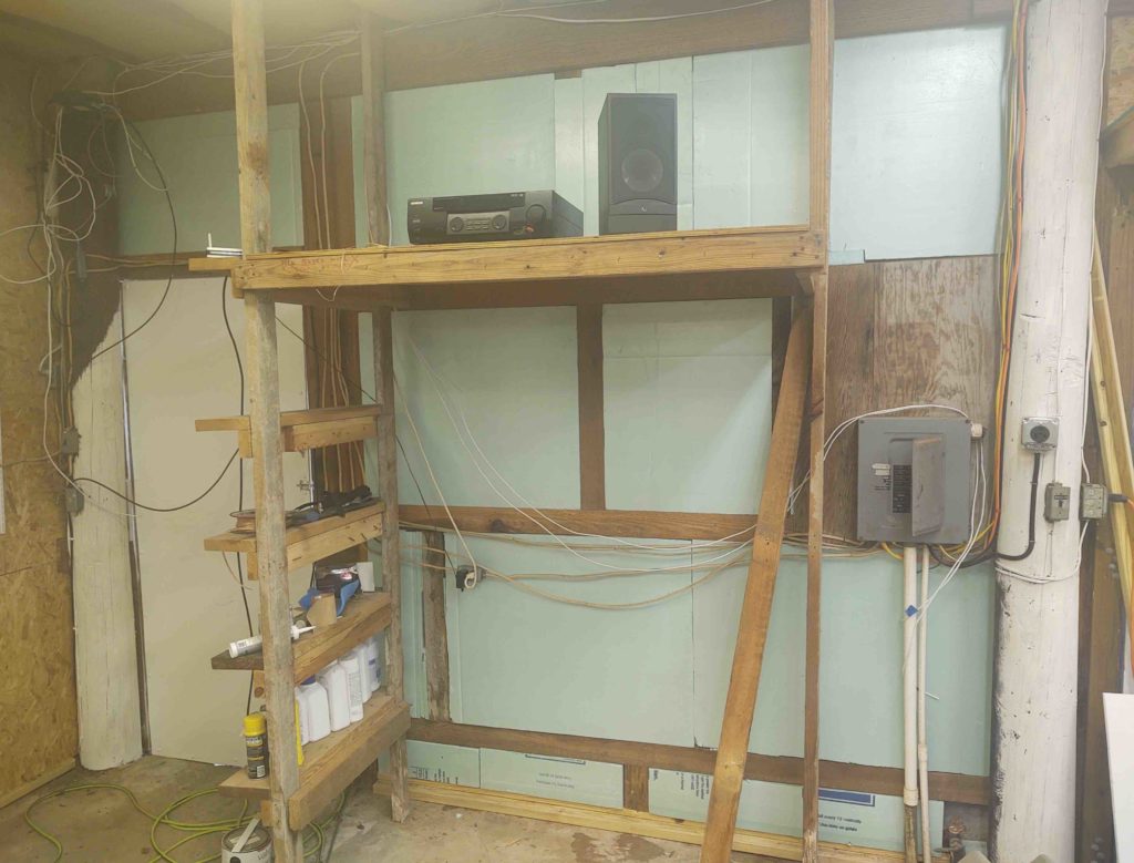
When I bought the house there was a myriad of junk that was left on these ginormous shelves that inhabit this area of the shop. While I do love storage, 3-1/2′ deep shelves x over 5′ wide was just a bit too much space being scarfed up with non-optimized storage.
I had long ago decided that I was going to convert this to a small office nook, or kiosk, which would have a taller built-in computer table, space for a small microwave, Kurig coffee maker and mini-fridge. It will also be where I house my binders, books, papers, etc.
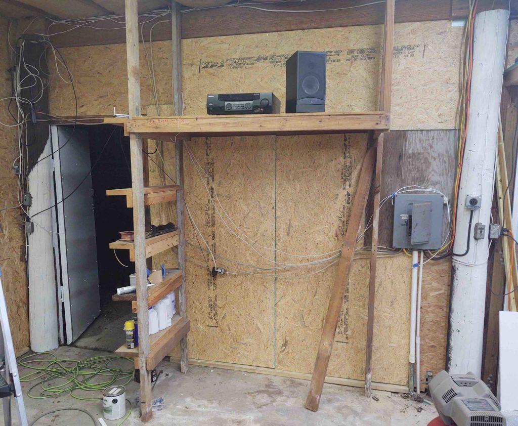
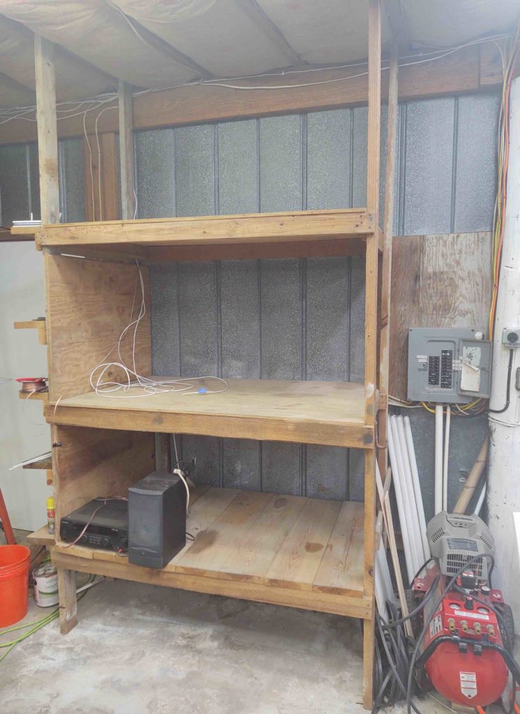
Here’s a shot of the shelves after a major clean up of all the stuff that was populating them.
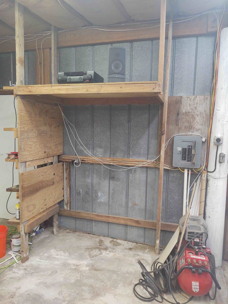
A few hours later it looked like this… not only does this give me access to insulate the walls, but it gives me a spot to build a desktop and put every I listed above in place (Uh, yeah, I forgot the stereo!).
The current top shelf will remain and serve as both a very large storage shelf and also the “ceiling” of the office nook. I’m currently undecided but may end up splitting the large top shelf by adding another shelf midway up to the ceiling.
It was getting a bit late so I called it a night in the shop and went back to a Long-EZ related project I had started messing about with last night and a bit this morning:
“J” hinges.
I have a set of these hinges that I picked up from the Cozy Girrrls and they are very nicely made. The pair I have will work fine for securing the front of the aft nose cover, allowing me to open up the back half of the nose like an MG sports car.
However, I need a pair of these “J” hinges (what I call them for my lack of knowing their true nomenclature!) for the front nose hatch, just a heck of a lot smaller than the ones I currently have on hand.
Having recently re-covered some instructional info on how to import a diagram into Fusion 360 CAD, I decided since it was fresh in my mind to finally get to using the Cozy Girrrl J hinges as a template in creating smaller versions for the front nose hatch.
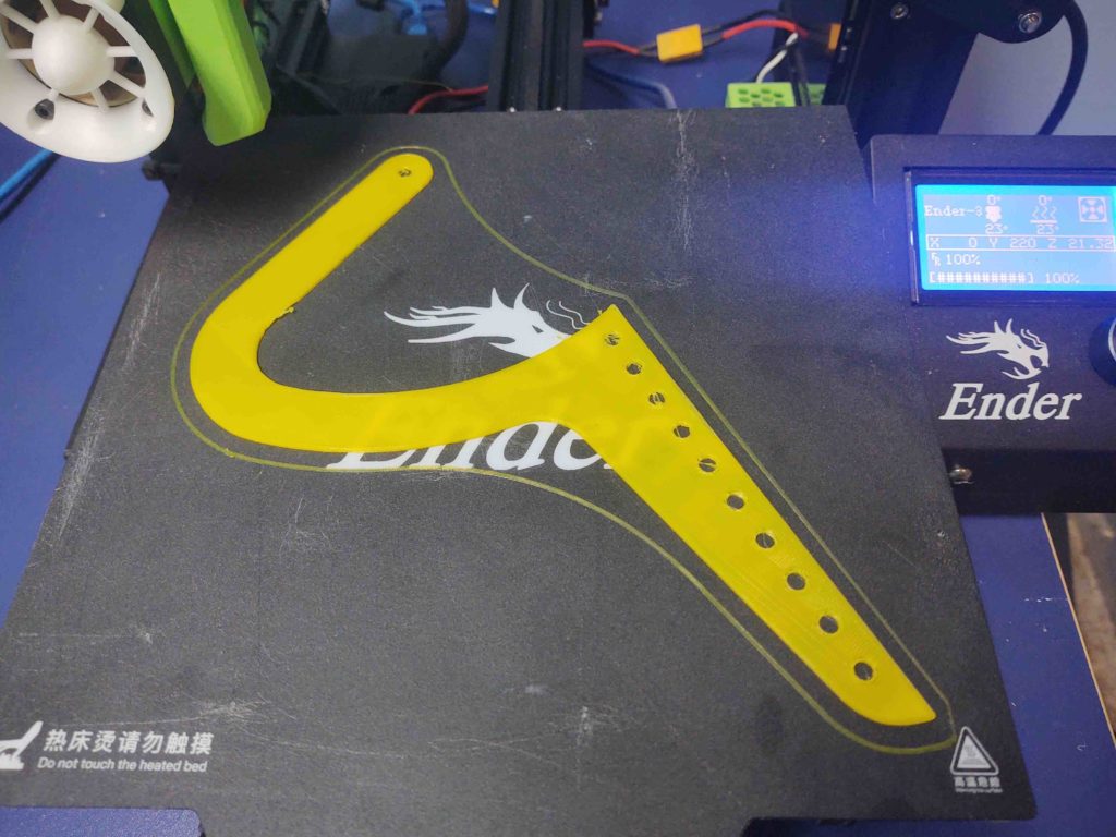
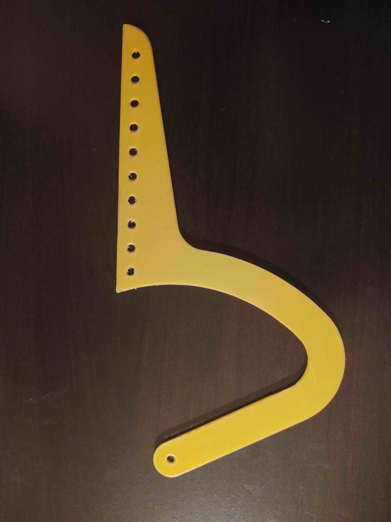
As you can see below, after I modeled up the J hinge I decided to simply print one out on my 3D printer.
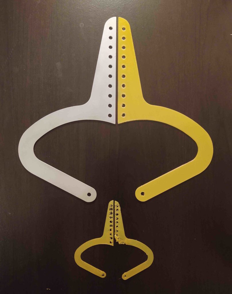
Here’s the new full size 3D printed hinge next to the real aluminum one. Below that are 40% versions of the larger standard sized hinges. I’ll use the small ones as a starting point to find the best size hinges to use on the front nose hatch (the small hinge on the right had some clear issues during the 3D printing process, but it will work fine as a size template).
I took this pic below to show my size comparison between the CAD model hinge and the real one, which is underneath this 3D printed hinge.
Tomorrow I’ll be back to work on the shop.
Cleary I’ve busted my “mid-April” estimated completion timeline, but I will trudge on nonetheless!
Today started out as quite another rainy and blustery day. As was yesterday. I will admit I was able to cobble together enough work sessions to actually finish the right front workshop wall segment yesterday.
Today I finished putting the power back in place on this segment of wall. I still have to run it back to the aft side wall and very aft wall for this circuit.
I also got busy rebuilding the workbench that –although quite strong– was in bad shape both alignment and configuration wise. First of all, just like the narrower workbench I put back into business to the left of this one, I added a lower shelf.
However, once I framed the shelf in –and with a seemingly good break in the weather– I ran to Lowe’s for some more supplies. Mainly 7/16″ thick OSB sheeting so I could cut and install the lower shelf top.
I then pulled all the rusty nails out of the old workbench top boards, trimmed the board ends a bit and installed them back into place. They may not be things of beauty, but these 2″ thick boards are heavy and strong! Since I stole a couple of rows of 2×4 (real ones) from the back of this workbench top to use for framing in the window and the back workbench legs, I replaced them with a section of the original middle roof beam that I took out when I installed the massive middle beams… that allowed me to remove the middle pole.
Since they are bit uneven on top, my plan is to at some point cover all these boards with a nice thick piece of plywood.
Here is the new look of the right end of my shop, with covered walls, new windows, and both freshly refurbished workbenches ready for action!
With this wall segment complete, that leaves the right front wall (where the small entrance door is), the left front wall (the middle is complete), and the front half of the left sidewall to complete: 3 sections total. Of those, the one I’ll be tackling next (tomorrow) will be the most entailed since it involves modifying a large shelf structure that I’ll convert into a work kiosk complete with a desk surface for a computer, binders, papers, etc.
We’ve had stormy weather all along the Atlantic Coast, and even as far inland as Tennessee… where sadly a couple of airports got hit pretty hard. This of course makes it difficult to pull all my saws outside to cut wood and foam, without everything getting drenched. What’s worse is that it’s been a bit sporadic, so I’ve had some false starts where I get set up, a few things cut and then come the downpours! …. ugh.
Part of getting the workshop up to speed is to get all the respective capabilities up to speed as well. I have a fair amount of machining and lathe work to do on a bunch of components to finish up the plane. I’m new to machining, and CNC, so there is a steep learning curve that I’m trying to stay out in front of as best possible to get this stuff up and running as soon as the shop is work ready.
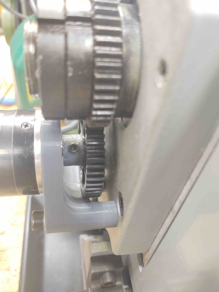
As I noted a few days ago, I 3D-printed some PETG parts for the spindle encoder installation on the lathe. This will be an integral part of allowing the Acorn CNC software to control both the speed (RPMs) and direction of the lathe.
Well, with the weather acting as it is today was perfect to engage in indoor activities. So I dusted off my epoxy skills and mixed a few grams of epoxy to then further whip into some wet flox. I used the flox to mount the 45-tooth gear (bottom gear in pic below) and slathered it on to ensure my stringy (fairly normal) PETG encoder spindle-to-gear attachment nub was as strong as possible.
One common issue with adding these spindle encoders to smaller hobby lathes is that once installed, the left side lathe gear & spindle cover can’t be remounted without some modification.
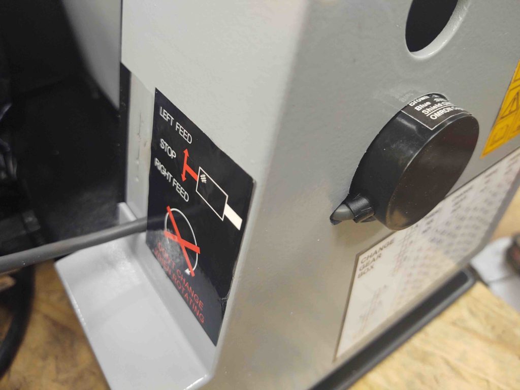
The modification is quite simple actually and only requires drilling a hole a bit bigger than the spindle encoder so it can peek through the cover. Depending on the configuration, the spindle encoder cable exiting the side of the spindle encoder must be contended with… as was the case with my install.
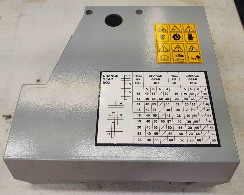
Here is the unmodified left side lathe cover [Note the bottom sticker regarding manual gear switching for threading ops will no longer be needed when CNC is used].
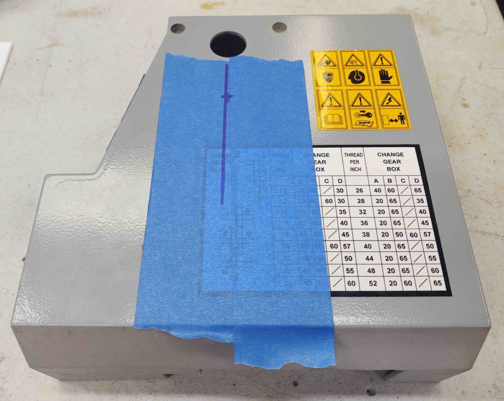
I applied some blue painters’ tape to protect the cover and the hole. I then measured and make my bullseye mark for drilling.
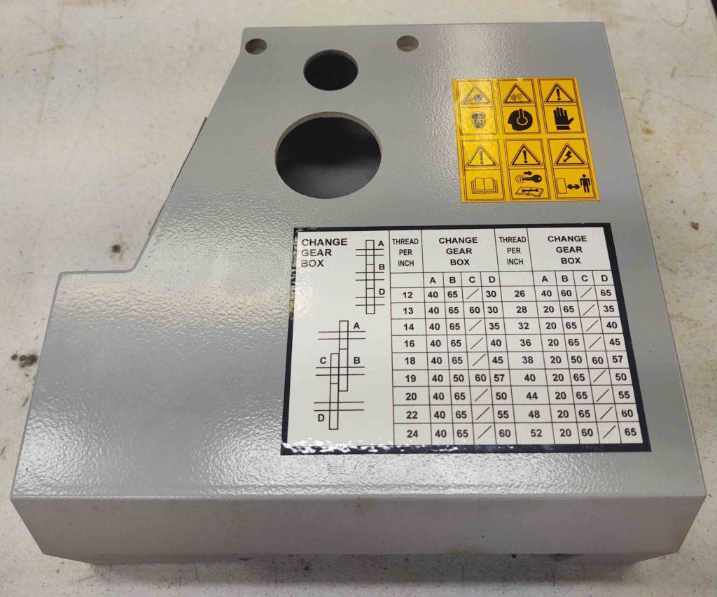
I was very pleased with the way the hole came out, although I was aiming for a certain position to optimize clearance for the cable that I just didn’t quite get.
I wanted the area of the hole closest to the spindle encoder to be around the 2 O’Clock position while the area farthest from the spindle encoder (aka the biggest gap) to be around the 7-8 O’Clock position. Again, to allow the best clearance possible for the cable.
As you can see below, my hole ended up being offset straight up and down: closest at the 12 position and farthest at the 6 position… which is much better than the opposite.
BTW, I used a 1-3/4″ hole saw to make the spindle encoder hole.
Here you can see that I had to make another little notch off the big hole with the Dremel Tool to allow the cover to be reattached without pinching the spindle encoder cable.
One more thing I did that I didn’t get a shot of was trimming the individual wires at the far end of the spindle encoder cable and crimping on D-Sub connector pins.
Overall I’m very happy with this install. It came out nice and clean and the configuration looks like it should work well.