After messing around with planning out the Triparagon top shelf mounted components install, I then got back to work on the air compressor bump out.
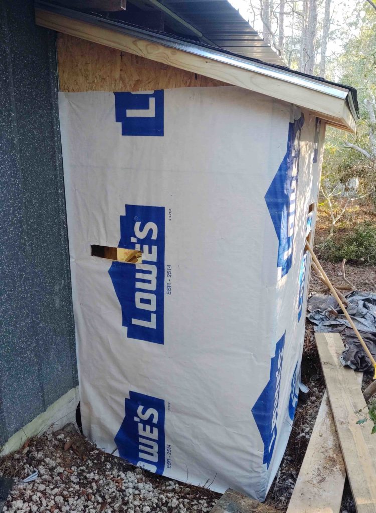
First up, I used the remainder of the new roof underlayment to wrap the exterior of the compressor bump out. The amount remaining after I finished was literally just a few square feet so it worked out perfectly and I used up the entire roll of wrap/underlayment.
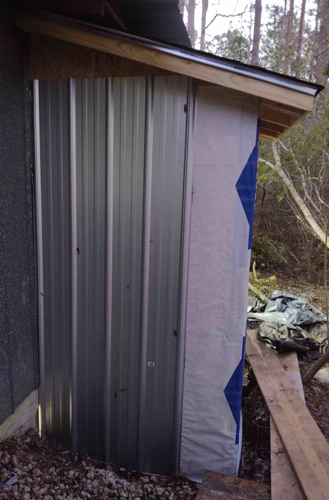
I then set the first panel and tacked it in place with a few screws.
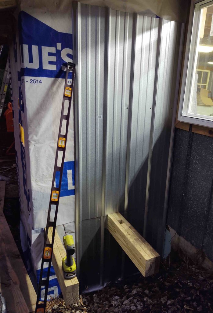
Next came the lengthy process of measuring out, cutting and fitting the lower panel around the inboard support arm for the exterior mini-split HVAC unit. By the time I cut the lower panel, deburred it and then set it in place it was nearly dark. And then after trimming the upper panel to fit and setting it in place with a few screws, it WAS dark.
Tomorrow will be the coldest day yet this year, so I plan on loading up all the old metal roof panels and delivering them to a nearby horse farm that wants them (for some reason). But I’m happy to be rid of them and donate them to someone who can get good use out of them. With my trailer hooked up to the truck, I’ll then grab some more large foam insulation panels for the interior of the workshop.
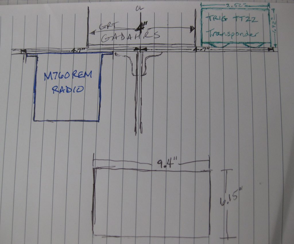
Mount WHAT you ask?? Well, the Trig TY91 remote COM2 radio, the GRT HXr AHARS, and the Trig TT22 Mode-S Transponder.
Since the weather has turned somewhat and it is quite cold during the mornings, I thought I would let the workshop warm up a bit before venturing out and working on it. And not surprisingly, I’m quite tired from the endless days of working on the shop. So I thought I would take the morning off to work on the plane just a bit. It’s been a while!
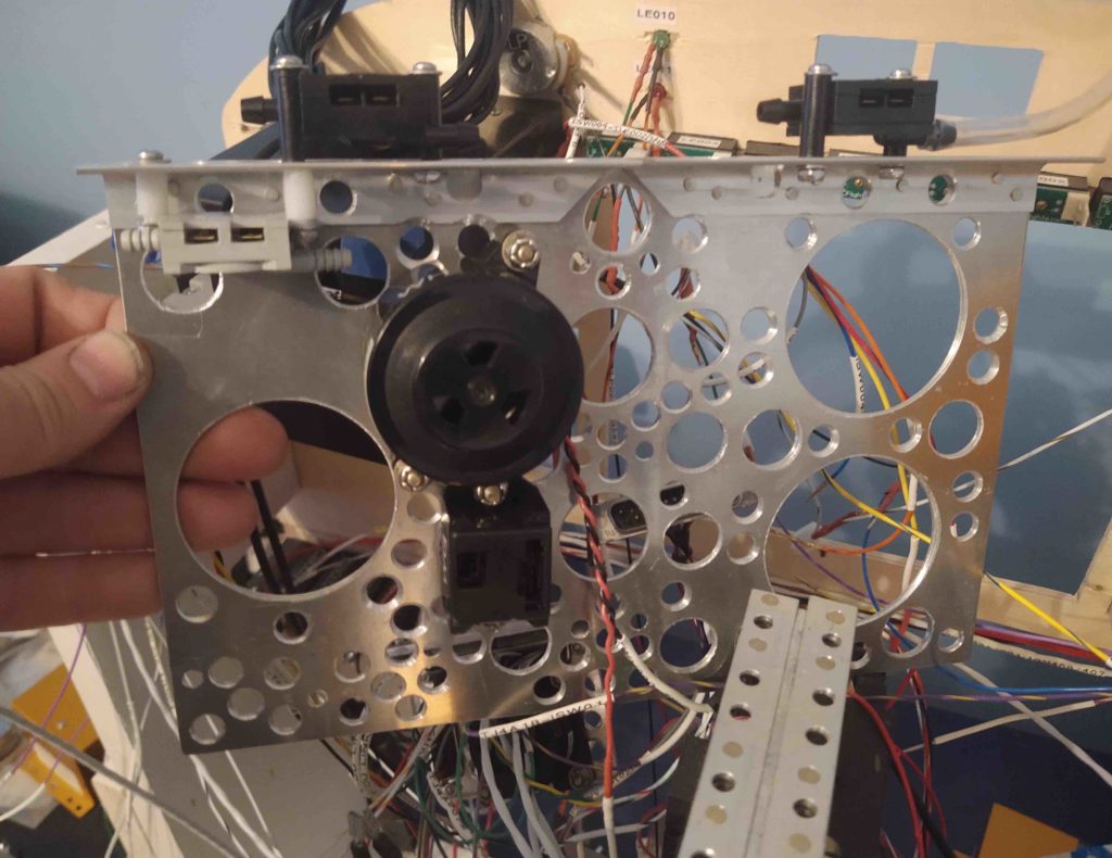
Of course, the easiest way to mount this stuff to the top shelf of the Triparagon is to remove the shelf itself. The physical removal of the top shelf is the easy part… getting it unencumbered even with the scant amount of stuff it currently has mounted on it is a bit more time consuming.
Attached underneath is the gear/canopy warning horn as well as the JBWilco gear/canopy warning system module. The tricky part here is simply keeping track of the small screws, washers and nuts after removing this stuff.
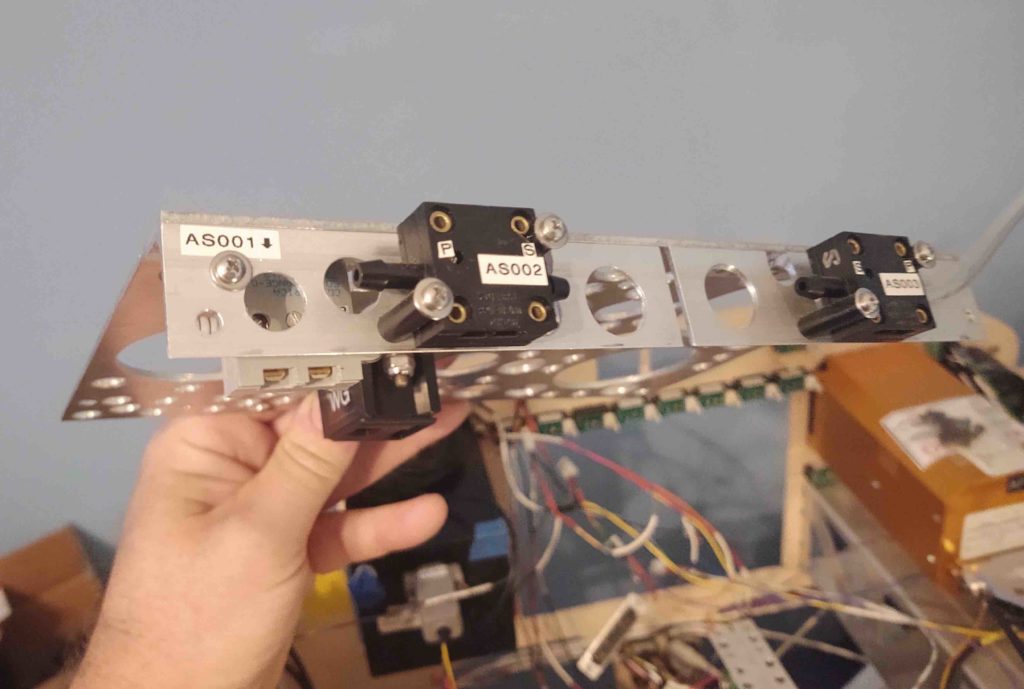
Then came the airspeed switches. Same thing… I want to ensure this all goes back together nicely and easily!
Here’s a shot of the JBWilco gear/canopy warning system module and the 3 airspeed switches.
Once the Triparagon top shelf was free of stuff, I could then get to planning out just how I was going to mount these 3 devices.
You’d think mounting 3 components to this top shelf would be a fairly simple and quick thing to do… but finding all the hardware, after deciding what you’re going to use, after figuring out what will fit, etc, etc, etc. . . . Wow, a couple of hours had already flown by after I rounded up all the hardware I was going to need.
Let alone figure out how to mount the two Trigs.
Why are the Trig components a question? Well, as I mentioned before in previous posts, I had not planned on using the Trig TY91 COM radio —but rather the MicroAir M760REM–when I finalized my design for the Triparagon over 3 years ago. Specifically, the top shelf where the TY91 is going to be mounted since the MicroAir was to be mounted underneath in order to, if you’ll recall, save space and minimize the width of the Triparagon’s top shelf.
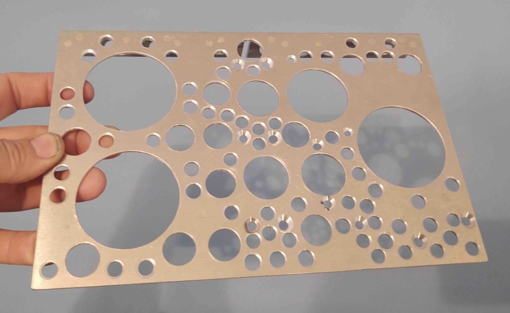
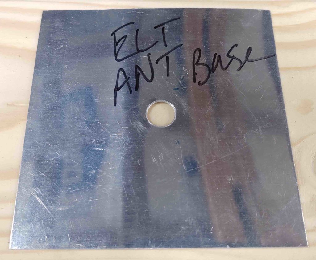
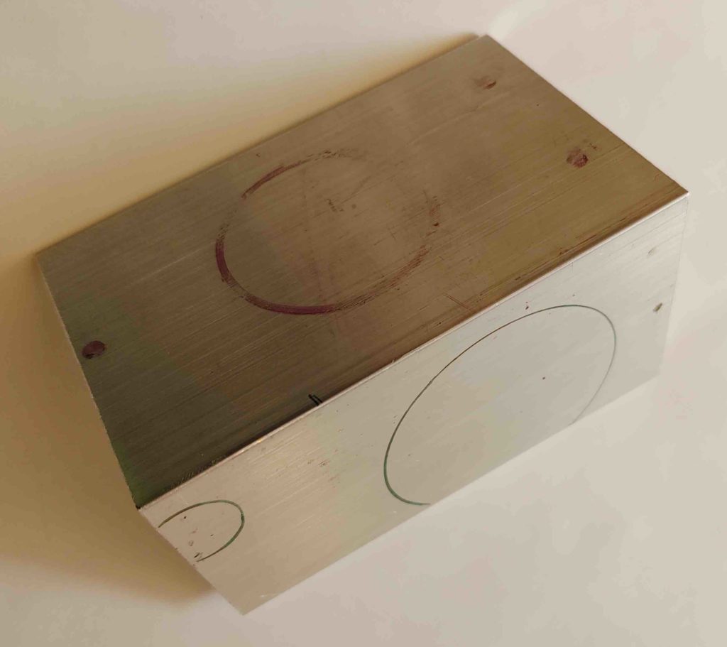
Moreover, since I “Swiss-cheesed” the Triparagon top shelf to save weight, I effectively removed all but one possible mounting point of the 3 required for the Trig TY91’s mounting adapter. Thus, I needed a decent-sized metal plate that will go on the underside of the top shelf to serve as the bottom-half clamp portion opposite of the actual TY91 mount on the upper side of the top shelf. As I was looking for the unused mounting plate for the EFII fuel boost pump since it was the perfect thickness (which I couldn’t locate) I found this old ELT antenna base (or maybe actually for a transponder?) that I constructed back in Germany.
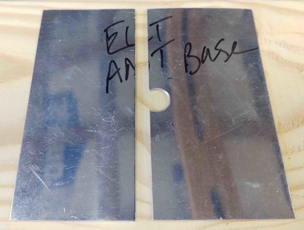
With my L2 transponder antenna in hand and since this is not required for my ELT, I know I’ll never need this antenna base as constructed. It’s a nice thin, yet strong, piece of aluminum so I lopped off the portion I needed and will use it to mount the Trig TY91 remote COM2 radio unit.
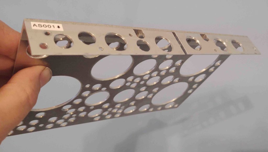
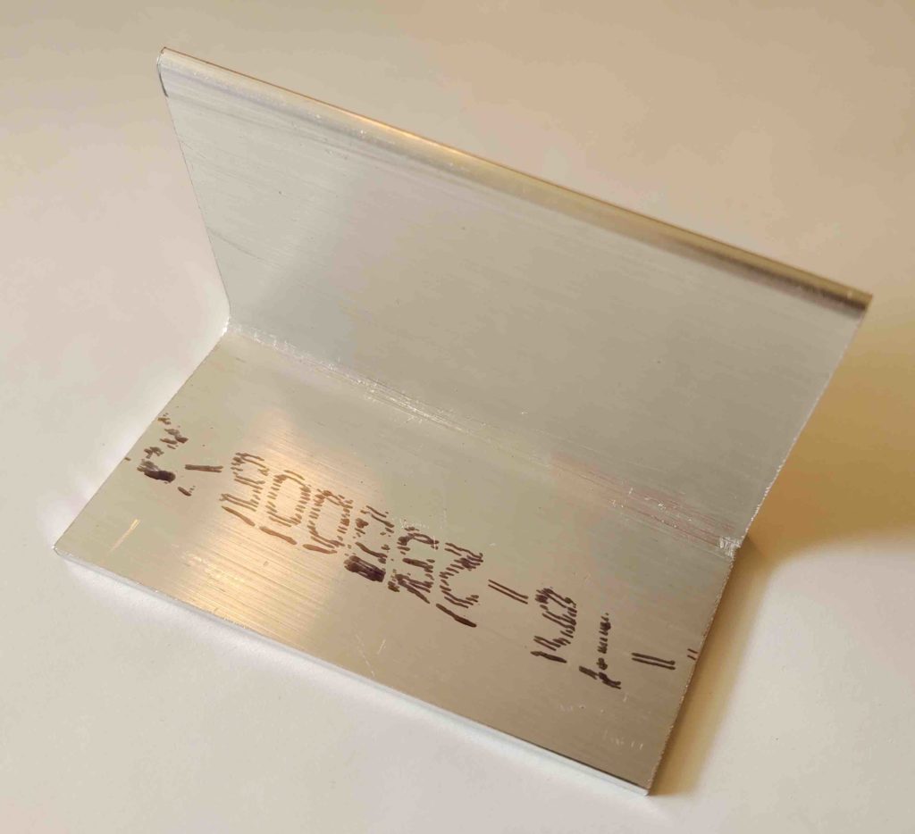
As for the Trig TT22 transponder mount… a few days ago while I had the chop saw out working on the roof I grabbed the stock of 2.5″ x 2.5″ x 1/8″ thick 6061 aluminum angle that I just recently ordered from Aircraft Spruce and cut it at just a hair over 4″ long. I would have preferred 0.063″ or maybe 0.090″ thick over 1/8″, which is a bit more robust than I need. But to get the 2.5″ width required this was all they had. Of course after I add some lightening holes it won’t be overly weighty anyway.
To remove as much unnecessary material as required, I angled the horizontal side that will be mounted to the underside of the Tripargon top shelf. I’ll do the same for the vertical side that the transponder mount will be attached to. Again, I’ll then make some decent sized lightening holes to get this as light as possible.
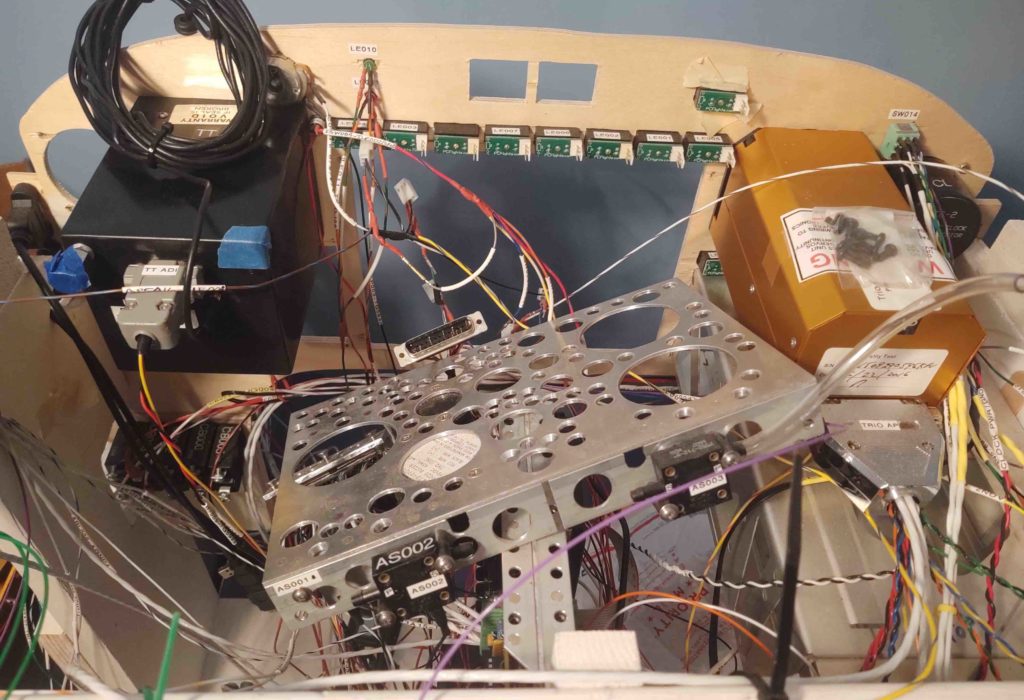
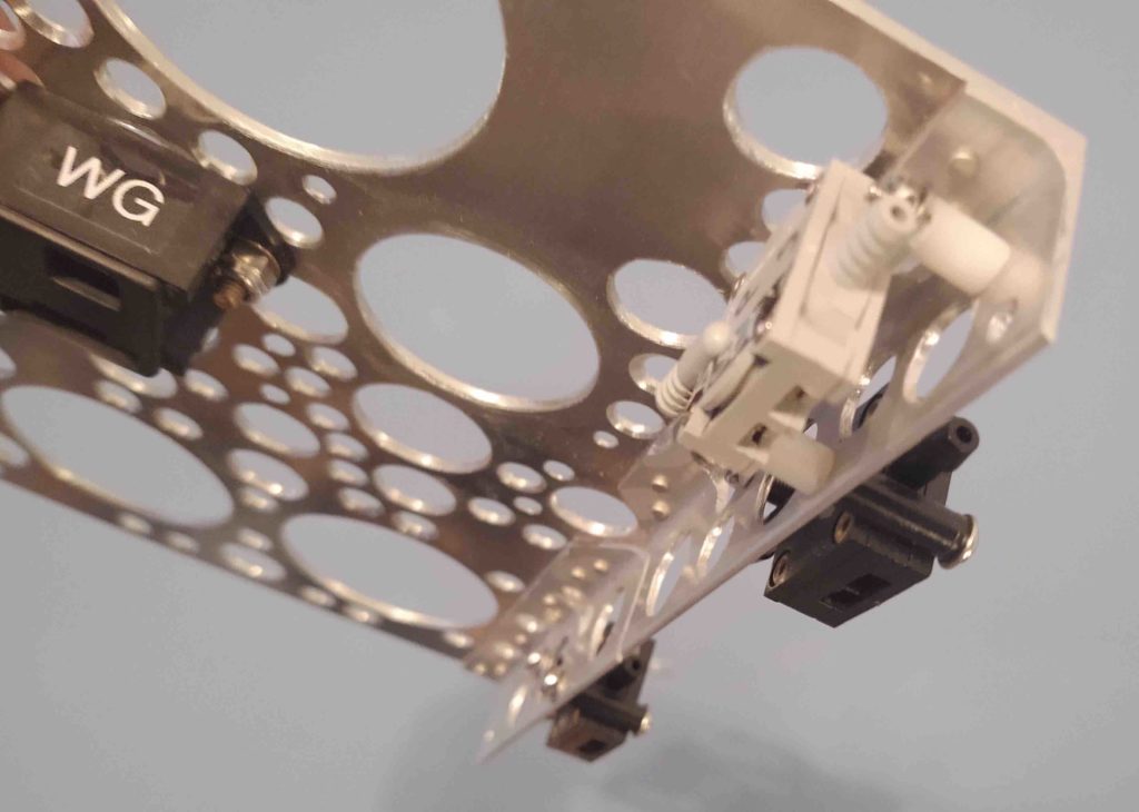
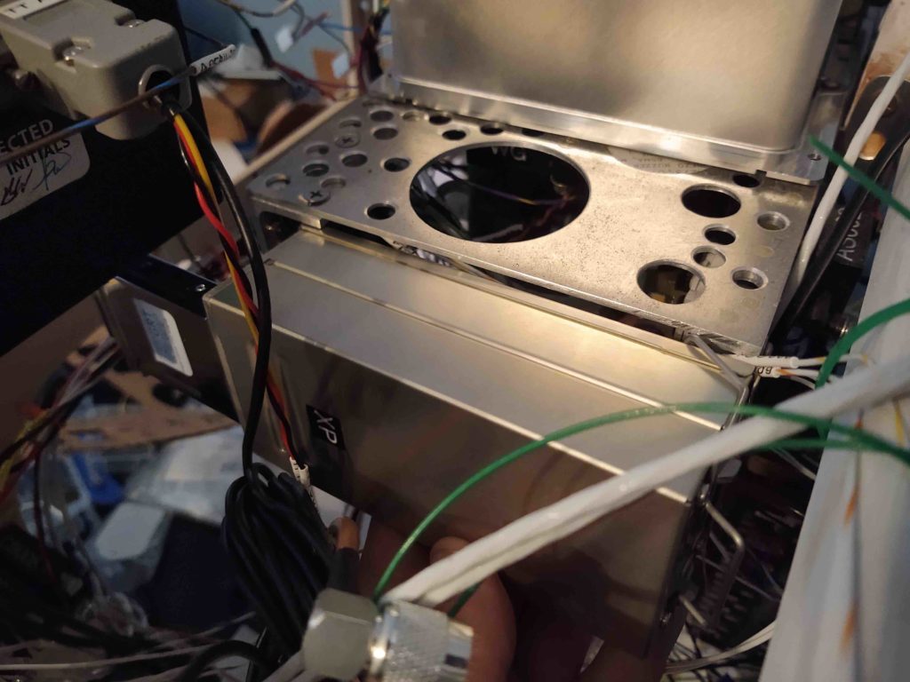
As a reminder, this bracket will allow me to mount the Trig transponder on the right end of the Triparagon top shelf. In the pic below the panel is left and the nose is right. Also, the bottom half of the AHARS is visible in its position at the center of the Triparagon’s top shelf.
I’ll continue to work on mounting these components as time allows. Speaking of available time to do stuff, a few weeks ago I made the decision that I wouldn’t repopulate the panel mockup with avionics until I get these 3 devices mounted on the top shelf.
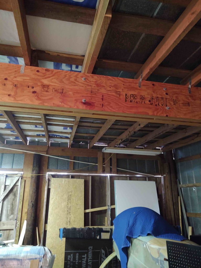
Again, because the days are so short, this is a recap of the last few days… bottom line is that the new workshop roof is installed! That makes the 2 biggest upgrade tasks on the shop complete: 1) the big center beam that allowed removal of the center pole, and 2) a new NON-Leaking roof
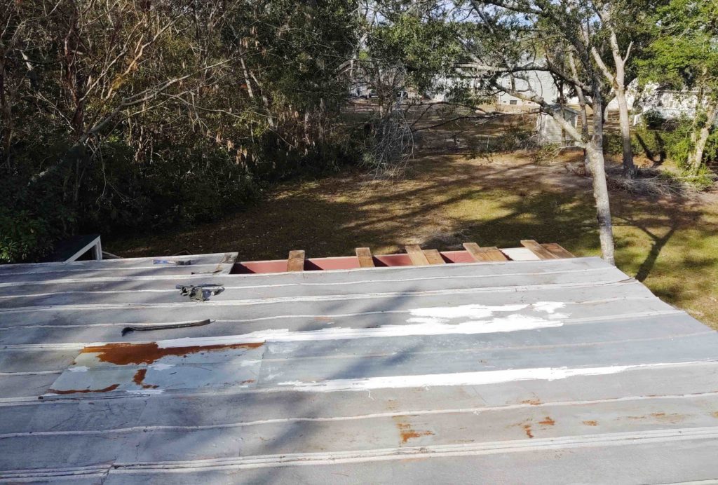
Since the weather was forecasted to be good for a couple of days, my immediate task was to remove 5 rows of old roof panels. At 2 feet wide apiece, this again would provide me a 10′ wide strip to lay in my 9 foot-wide underlayment.
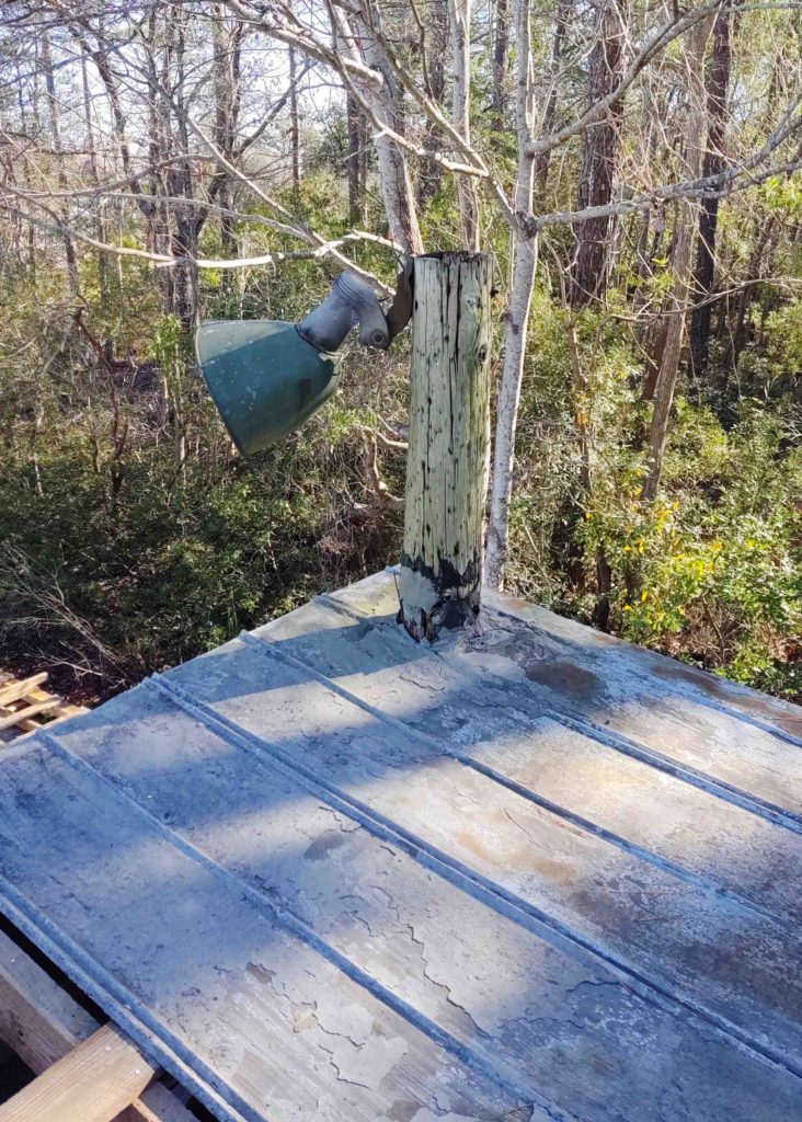
Before I removed all the old roof that was serving as a work platform as well, I set about to dispense with a somewhat iconic feature of the ‘ol workshop: the 1930s era old Soviet surplus (looks like!) light. This thing has cast iron mounts and weighs a ton…. seriously!
Anyway, I removed the light from the corner pole, which, not surprisingly, is a huge leak source at the front corner of the shop.
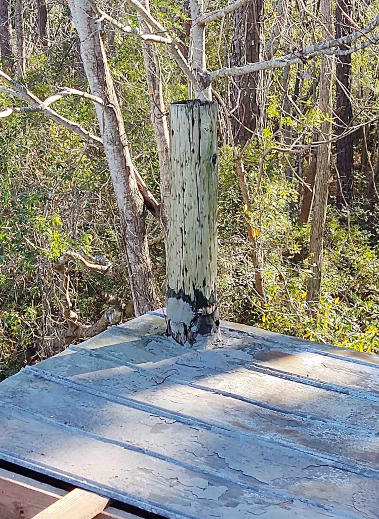
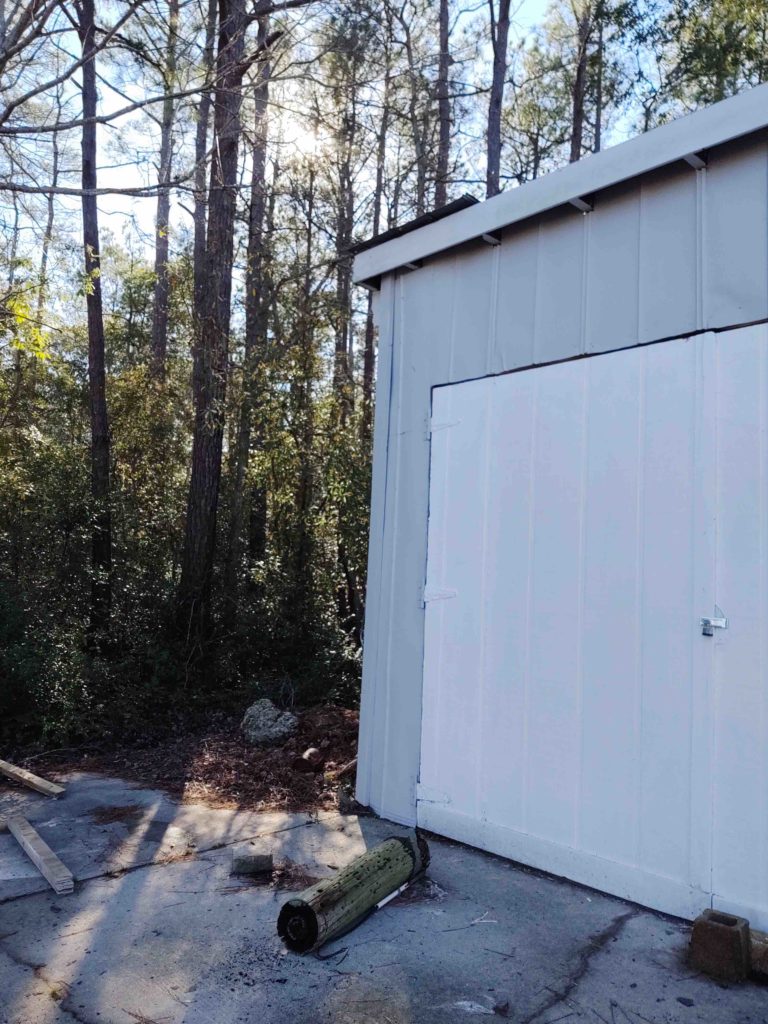
I then grabbed my cheap trusty Harbor Freight chain saw and ridded myself of ye ‘ol corner post.
And down she came with a mighty thud!
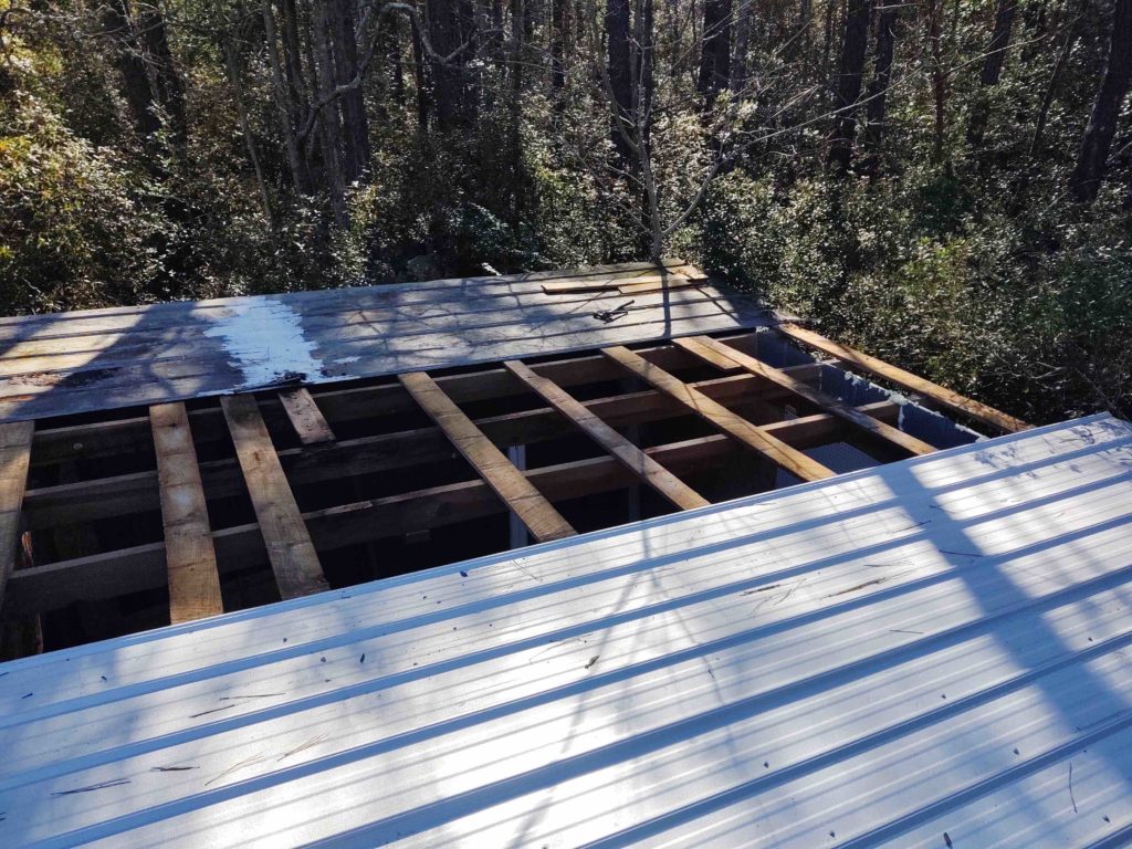
Below left is the last vestige of the old roof and below right is nothing but future opportunities! haha!
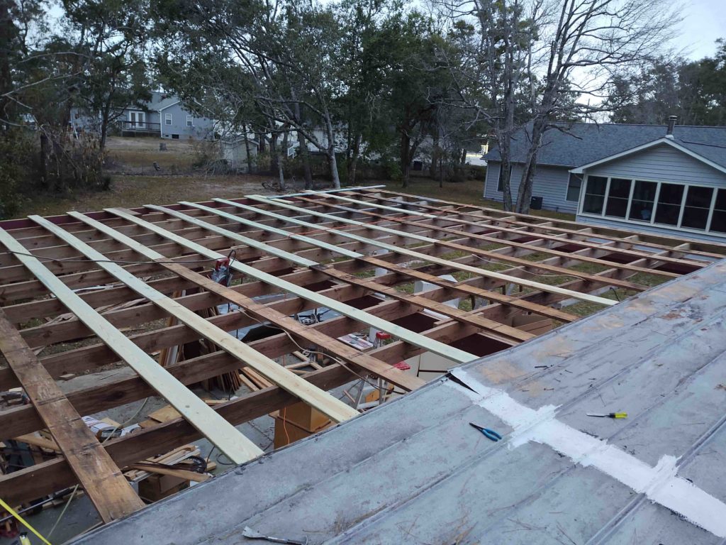
I then set about the multi-hour effort of replacing bad joists and purlins.
Before it got too dark I then tacked in the 9 foot-wide strip of underlayment.
I was able to get the first panel installed before it got way too dark to see. In fact, I was using the flashlight feature to set the screws to the proper height by the time I finished installing the first of the three 3′ wide panels. I then set (not installed) the other 2 panels in their respective places and called it a night.
The next morning I screwed panel #2 into place, then attached the final strip of underlayment in before attaching panel #3.
In then installed panel #4 of this final effort… the last new panel! The new workshop roof is installed!
(minus some trim that is on order will go on the front and carport side…)
Here’s another multi-day wrap-up of my workshop re-roofing project. To reiterate, being a week out from the shortest day of the year is having an impact on getting this thing done. Once dark it’s really hard to determine setting the screws at just the right height: too much and it crushes the rubber washer and allows for eventual leakage; too light and there’s not enough clamping force on the washer, allowing for –yep– leakage.
Anyway, with that being said, I have been making consistent progress and the weather has been proving to be a little better than what was forecasted, which has been a huge help.
Below I’m just finishing up installing the panels that will cover up the front section of the air compressor closet roof. In fact, when I removed the old roof panels I was able to officially finish the compressor bumpout roof by adding the one last row of shingles at the top with some roof felt flashing to ensure no crazy sideways rain makes its way in.
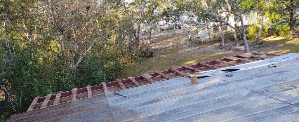
Since good weather was reported for the next day, I opened up more of the roof by removing a few rows of old roof panels. I had meant to remove another couple of rows to expose –again– the requisite 9′ swath that allows me to roll out and add the underlayment across the purlins… but alas, it got dark and I ran out of time.
So here’s the ending progress of the first evening of this post.
The next morning I removed my next couple of rows of old roofing panels . . .
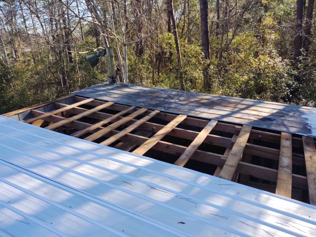
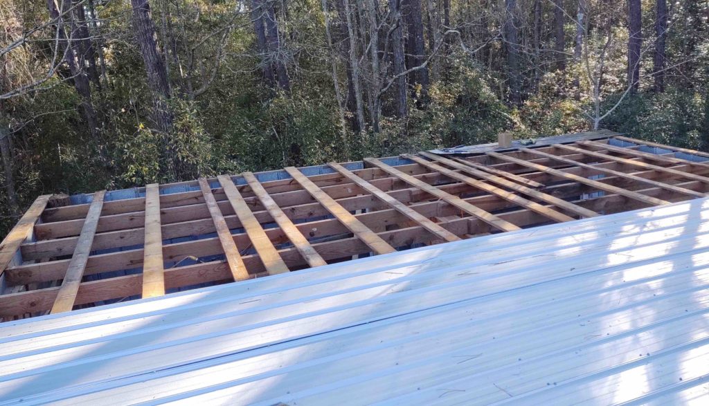
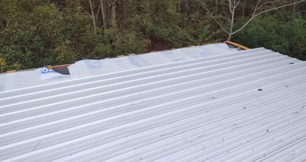
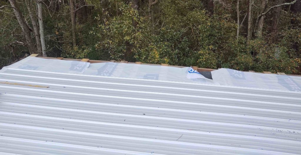
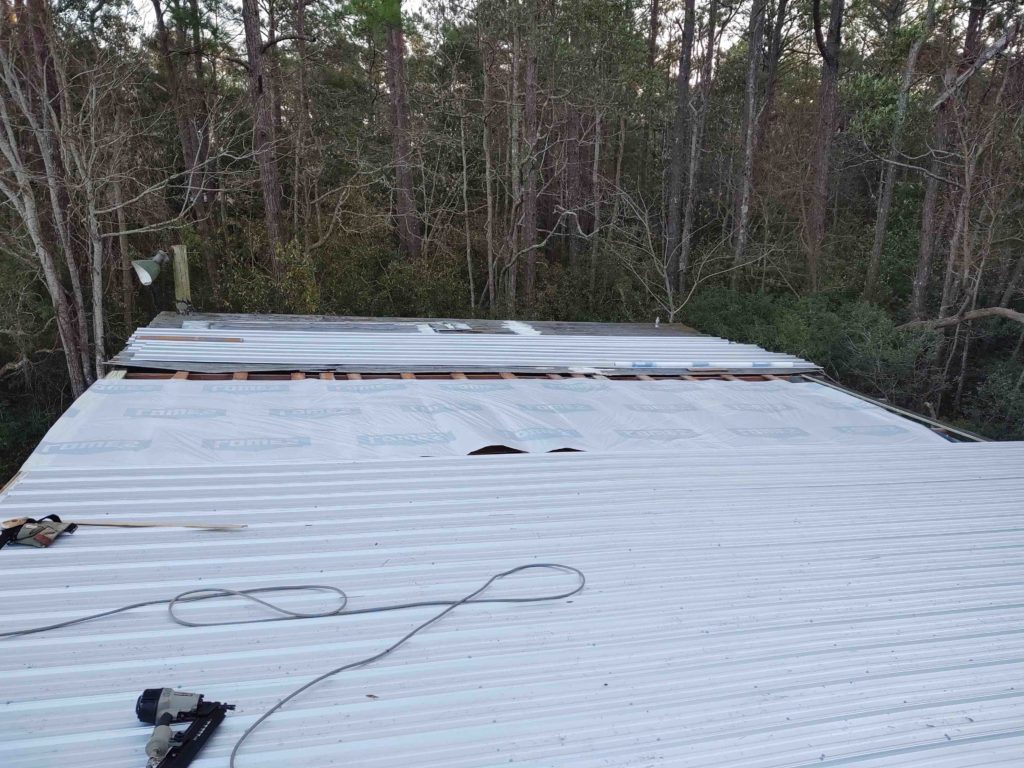
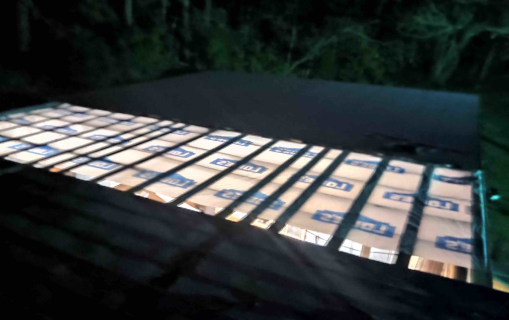
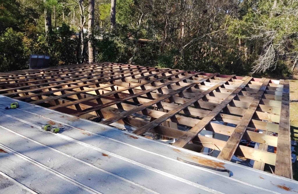
I then rolled out and stapled the underlayment in place…
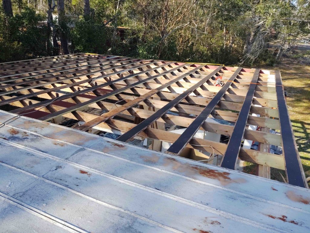
A top view of the underlayment. It was a bit tricky to get the underlayment installed today because it was quite windy.
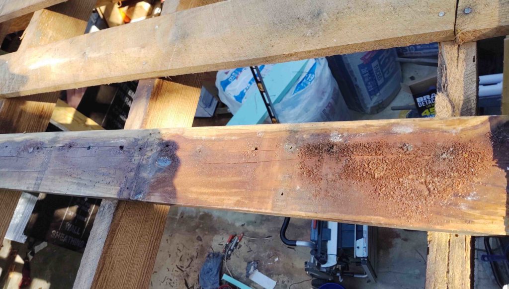
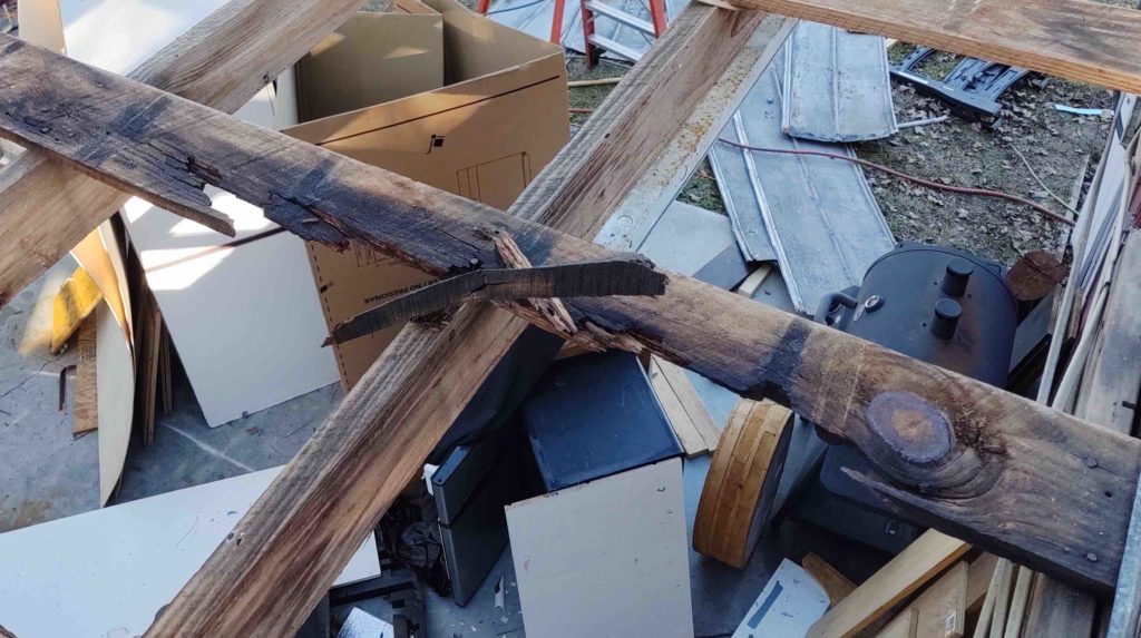
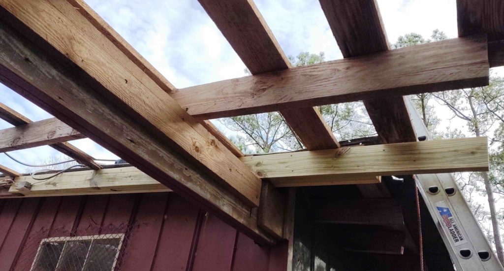
The time buster for this project is not removing the old panels, or installing the new ones. It’s the carpentry involved in cutting out the old rotting purlins, cutting new ones and then installing them.
Believe me when I say that this pic does NOT capture how rotten this piece of wood is, nor does it show the brilliant red of the rusted metal that accumulated over the past 30 years.
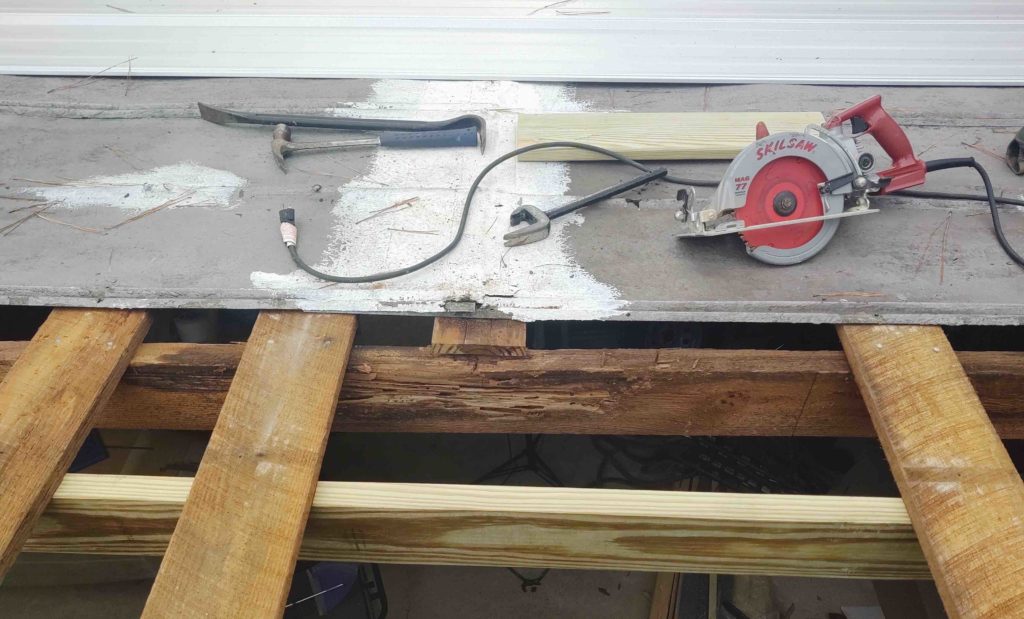
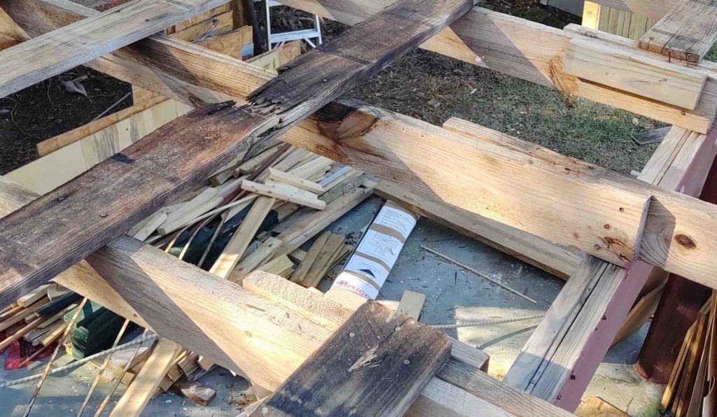
Here we have the rotted purlin above removed, but it was so bad that it really did a number on the joist below it. There was about a 5-foot long 2×6 attached to the face of this joist that I pried off to reveal some pretty bad carnage from a lot of years of water pouring down into the heart of the joist. Continuously wet wood is of course an open invitation to termites and they did a number here, so the bad part of this joist had to be removed. Notice the new pressure treated joist on the scene and ready to be installed.
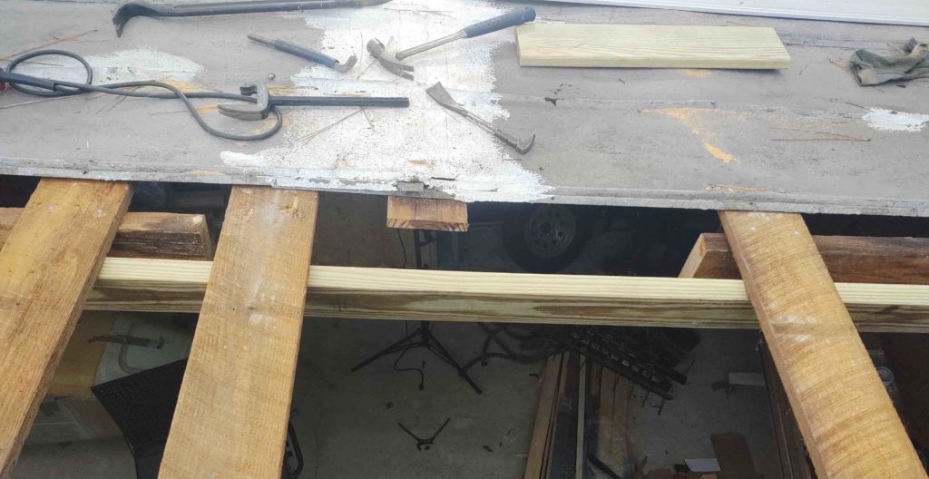
Here I’ve cut out the worst part of the rotten, half-eaten joist and am ready to install the new bridging joist. For added support on the interior I normally use simple untreated wood, but since this problem joist clearly had some type of wood eating insects in it, I want to ensure any new wood won’t be tempting for them if it were to happen to get wet for any reason.
Here’s the new joist nailed in place. Again, this is just one example of some of the structural stuff I’ve had to rebuild before getting to the actual re-roofing tasks.
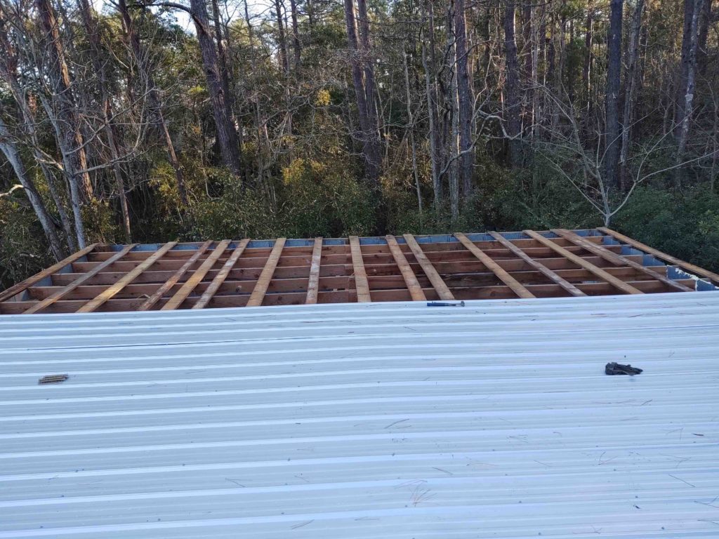
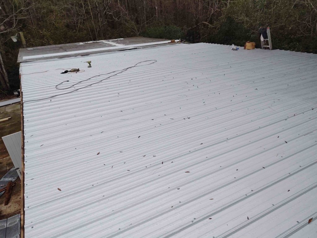
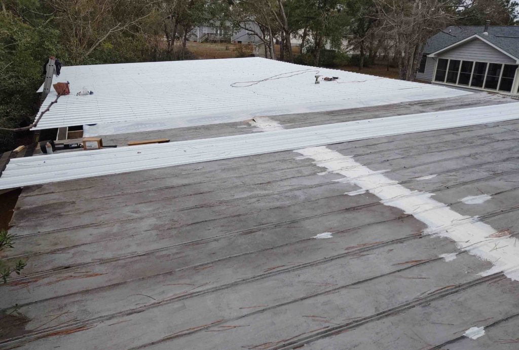
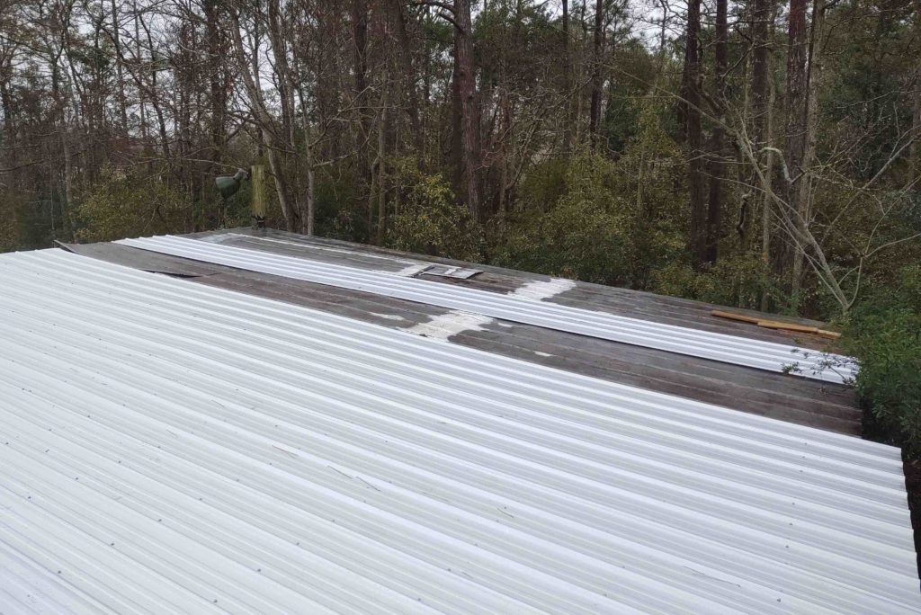
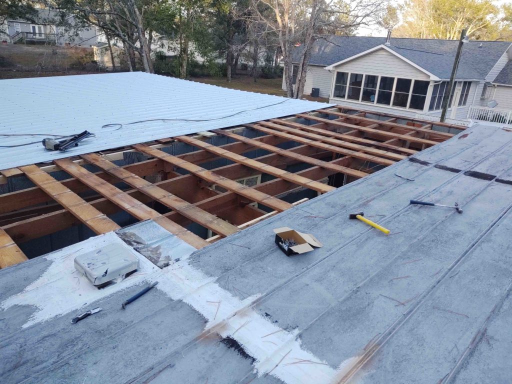
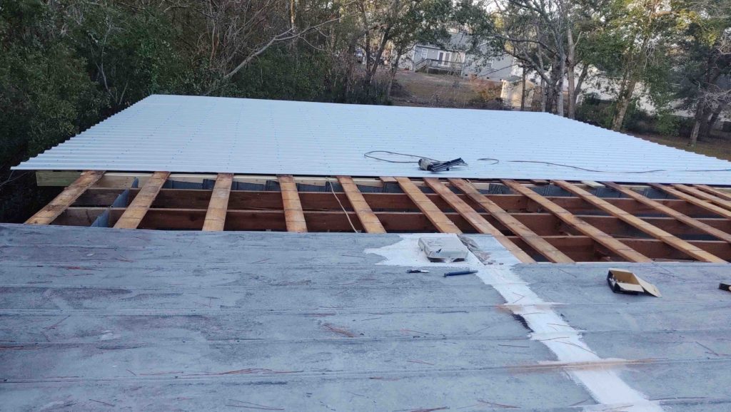
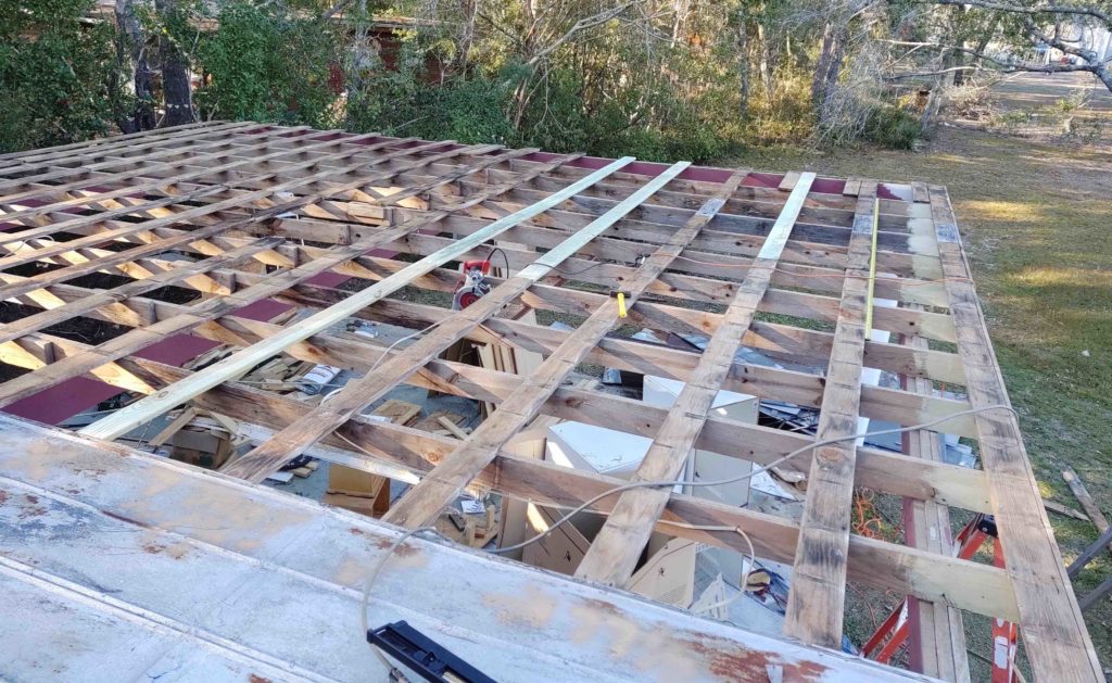
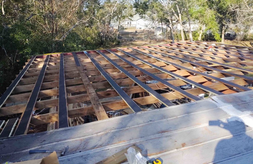
Here are some shots of the latest progress on the new roof panel installation. As you can see, not much left of the old roof panels… 12 feet in width to be exact, or 4 new roof panels left. I have one panel pre-deployed on the roof, obviously meaning that I only have 3 left on the ground that need to be brought up.
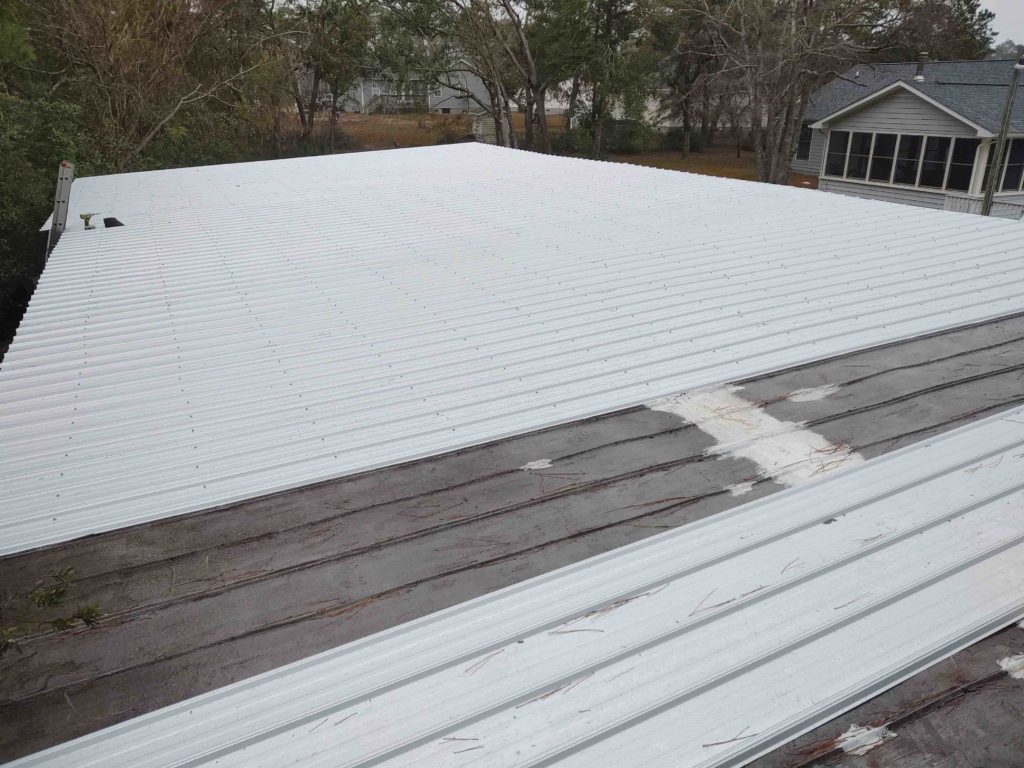
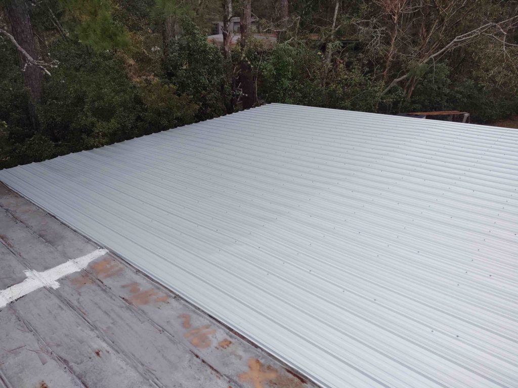
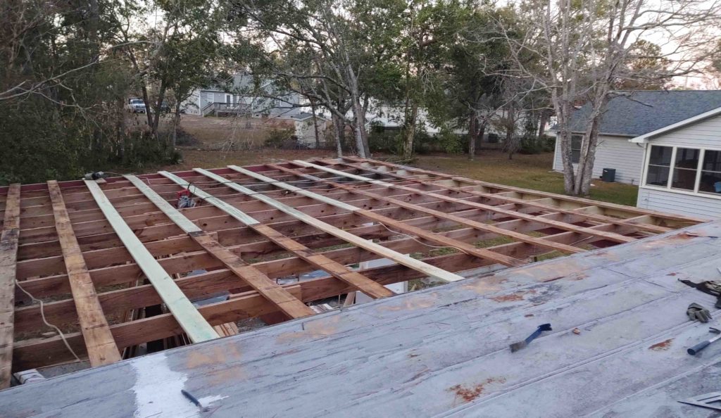
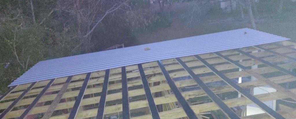
Here’s a long view of the re-roofing progress. Another couple good days of weather and I should have this baby knocked out!
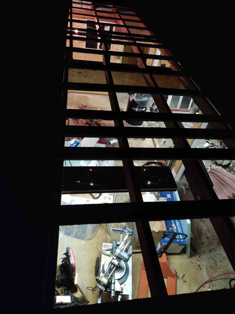
And an interior shot of my progress. I’m clearly into the last working bay of the shop with the new roof panels installed just over/inside the leftmost set of doors.
I had just finished taping and physically installing the last new roof panel for the day when it started drizzling. I then installed all the screws while it rained lightly. I scrambled to get the tools down under cover to keep them dry. And then a few hours later it really started to pour.
The heavy rain is significant because I was working in the shop for quite a few hours as the rain really came down, and it was definitely loud. I was figuring out my ceiling lighting configurations, all the while keeping an eye out for any leaks. I have to say after an hour or so I finally felt confident that the new roof was upholding its end of the bargain and proved (thus far at least) to NOT leak!!!
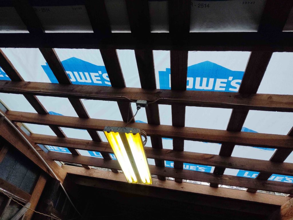
With workshop made up of essentially 3 bays divided down the center by a left-right beam, I basically have 6 areas, or “quadrants,” if you’ll allow me the technical misuse of that term, to plan for lighting-wise. Since I had access to the center aft “quadrant” of the shop (just in front of the compressor closet) to set up my ladder, I decided it would be my initial test area for putting in some fluorescent lights that I brought from my garage in Virginia, and a few new LED light bars that I bought to fill in some of the coverage to eliminate any light gaps.
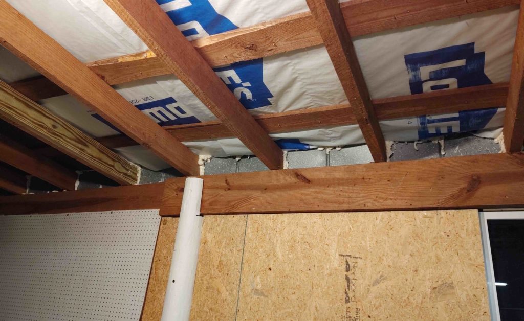
Before any lighting could go up, I needed to insulate the ceiling first. But, I had to back up even a little further and seal the significant gaps between the metal siding and the joists poking out the back of the shop, and through the top of the siding. Before I got serious on working with the lights, I used some expanding foam out of a can to fill in those gaps…
With the upper exterior wall joist gaps filled and the foam cured, I then added a few batts of insulation in between the ceiling joists where I wanted to mount my 4-bulb fluorescent light that I’m transplanting from my Virginia shop.
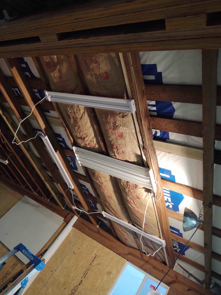
Here’s a shot with just the LED lights on… there’s actually one more in the group that will go on the right side about where the shop light is clamped to the joist. Since the previous owners had all their fluorescent light fixtures –mostly one per bay, or “quadrant”– plugged in to a ceiling mounted power receptacle, I decided that for my LED light bars I would simply circle the wagons and place them around the bigger existing Fluorescent light bars. Since the LED light bars allow a max of 4 per series of lights, this obviously works out to one big fluorescent light bar in the middle with 4 LED bars around it in a square pattern for each of the main work bays, or the 4 left side “quadrants”… main here being the area under the big cross beam where the Long-EZ project will be situated. Over on the right side (2 “quadrants”… fore & aft) where my long work benches and shop equipment (milling machine, lathe, drill press, etc.) will be located, the lighting will be just a tad different than over where the airplane will be located.
Since I opened my first pack of insulation batting, I quickly put one of them up in the air compressor closet before shutting the shop down for the evening.
So clearly still a lot to do on the workshop, but with the roof project winding down I think over the next week to 10 days the shop will transform quite a bit into what I need it to be to get back to work on my plane build.
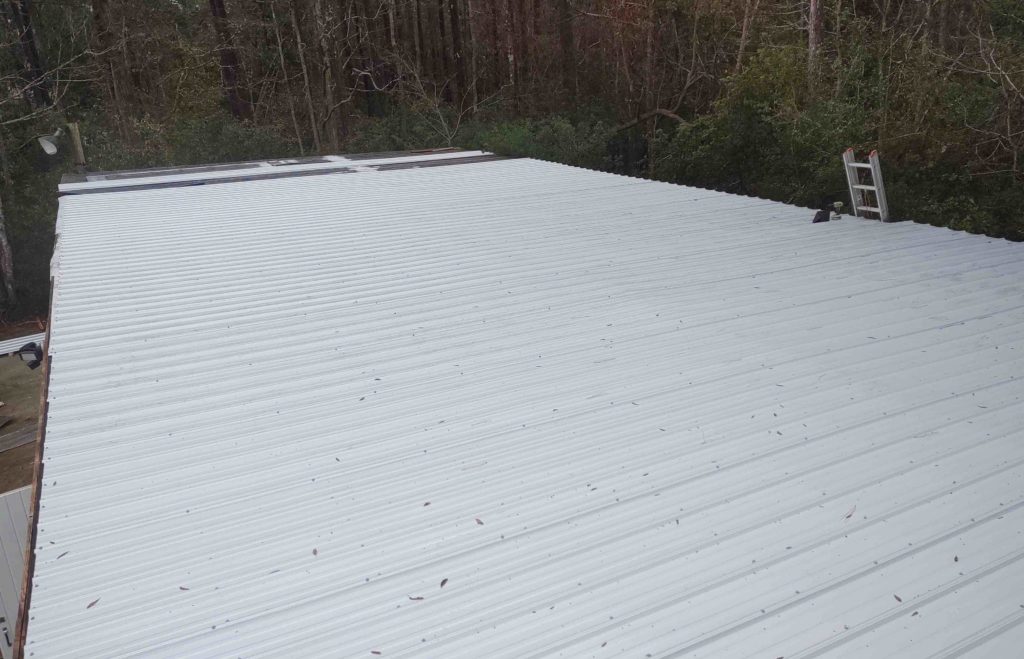
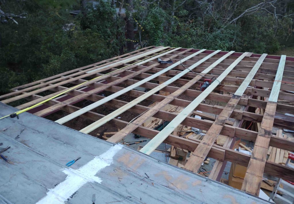
It’s exciting to see the roof come a lot farther along, not so much in the reporting of it. Nonetheless, here’s an overview of my roof replacement efforts over the last couple days.
I removed 5 rows of the old 2′-wide roof panels to give me a minimum 9′ wide clear spot on the top of the roof to allow me to add in the underlayment, which is on a 9′ wide roll. This also gave me clearance to install 3 more 3′ wide panels.
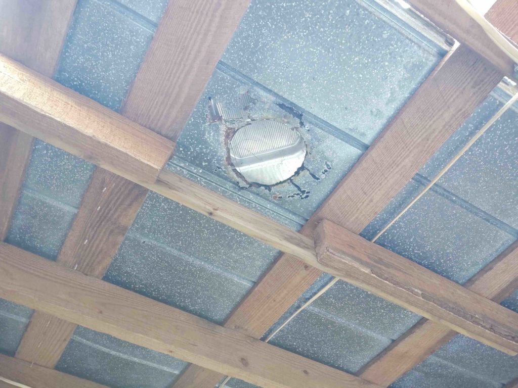
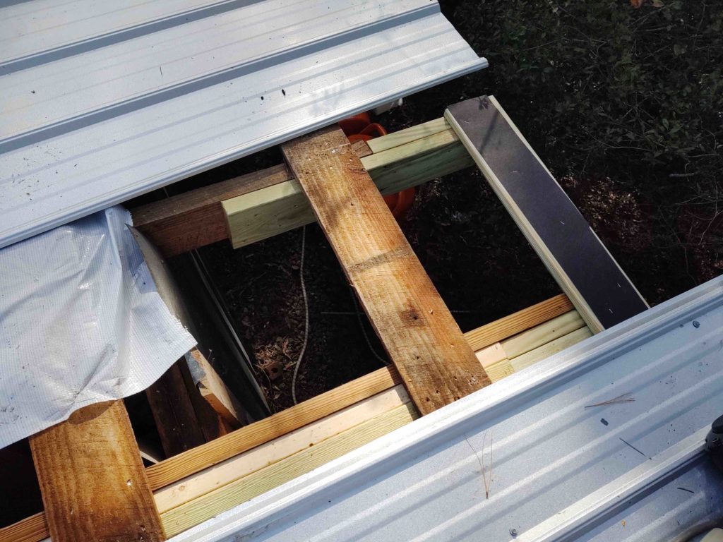
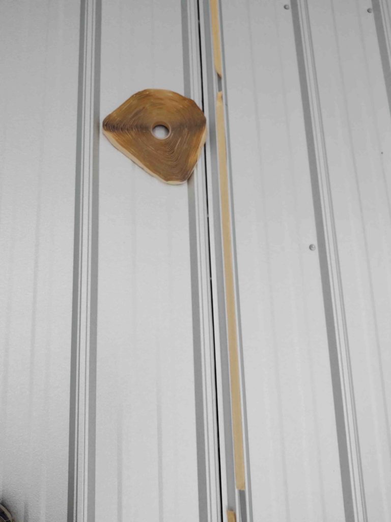
Apparently there had been a wood stove in this workshop at one point, and they covered the hole with a roof vent… quite a few screws to contend with getting that detached from the purlins below it.
There was also a big gap in the joist immediately below the vent that was cross-supported by a 1×4. I grabbed an untreated 2×6 (since this will be an interior heated space) and nailed it alongside the sparsely connected joist segments.
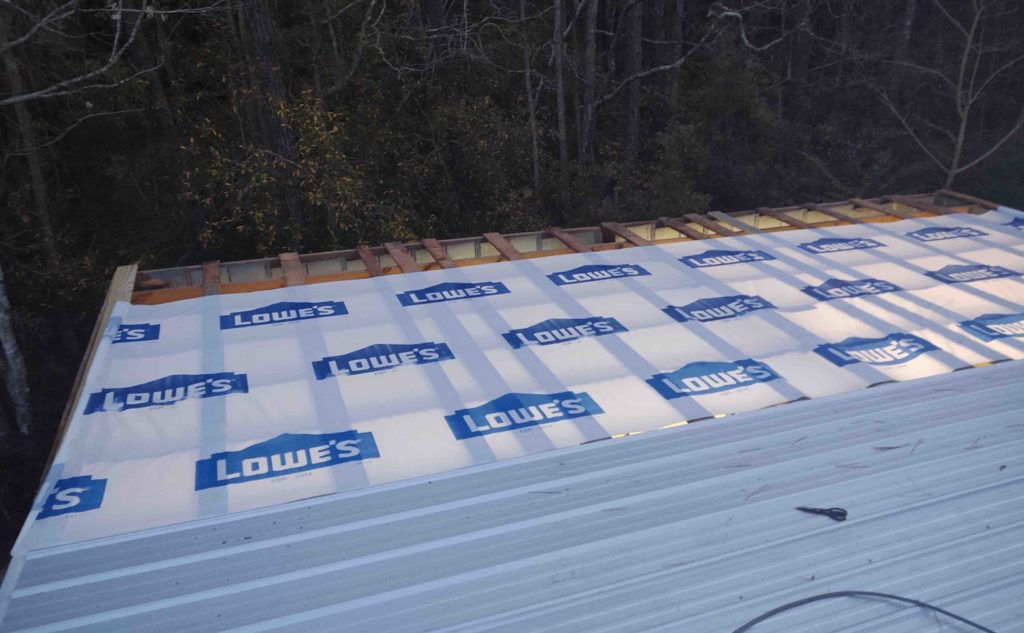
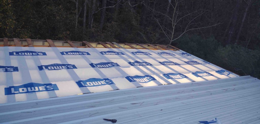
I then added the underlayment (house wrap does fine according to the roof panel manufacturer) across the purlins from front to back.
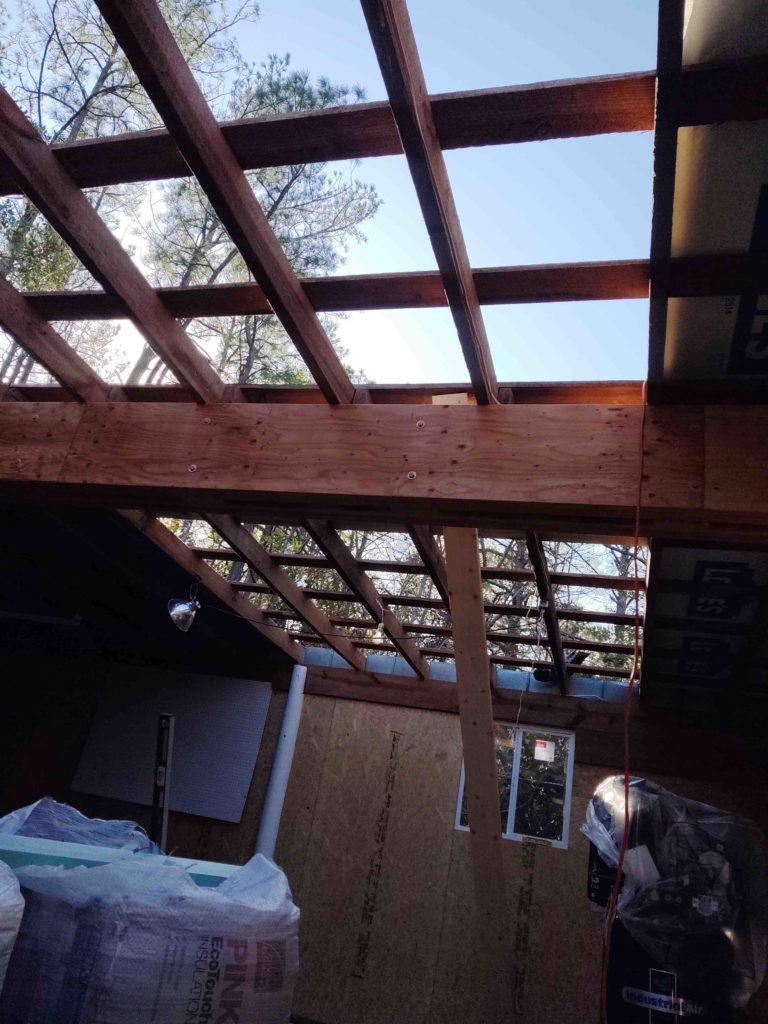
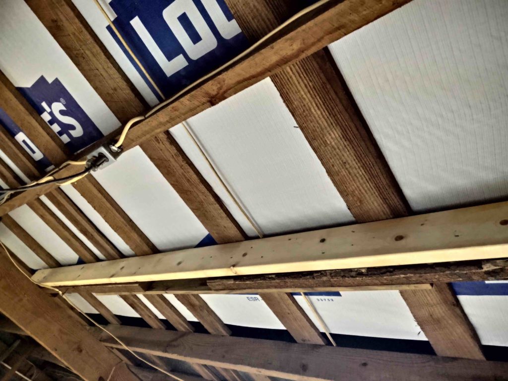
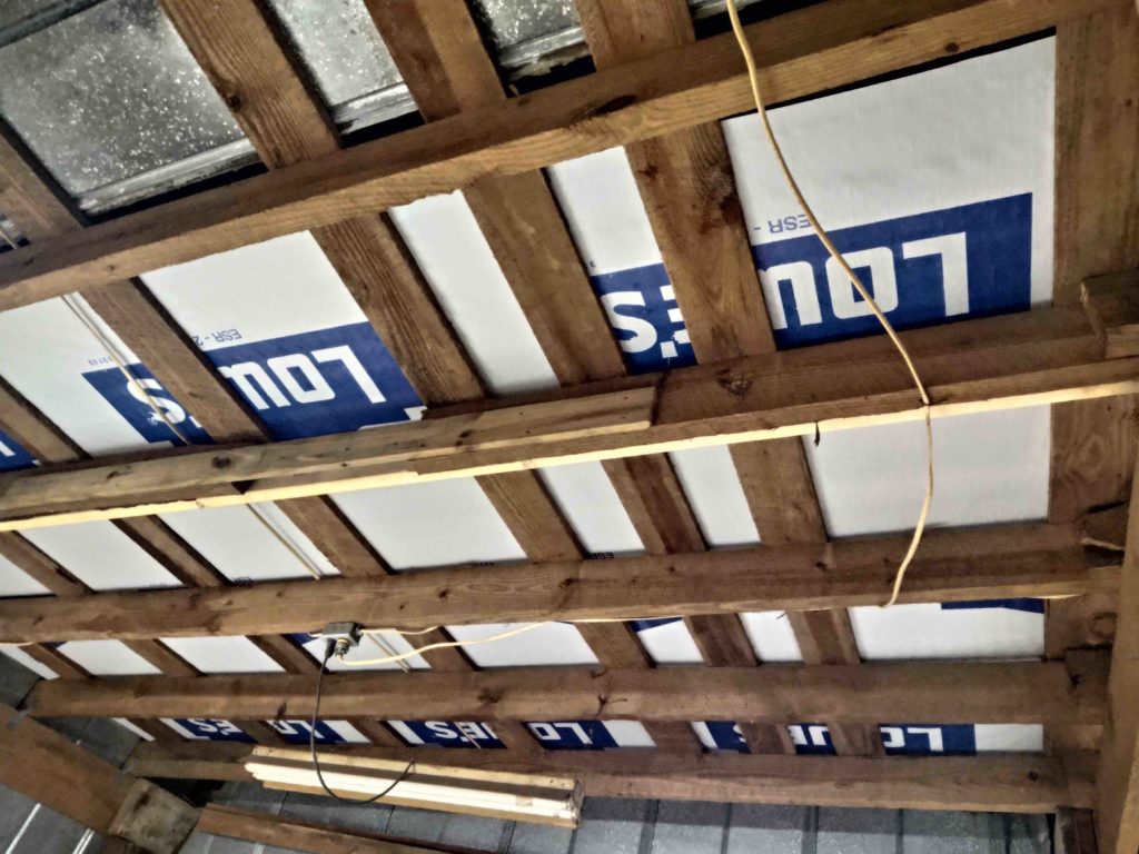
Here’s a couple of shots of both the underlayment and my added joist from the inside.
It was too dark to finish screwing the added 3 panels into place, so I waited until the next morning to do that. But I first had another task to knock out before I could do the final attachment of these new panels.
The difference of the new panel lengths on the back overhang between the carport and main workshop is 1 foot. On the old roof it was more like 2 feet. The best spot to place the ladder was at the back left corner of the shop, just adjacent to the longer panels of the carport. This allowed me to have a spot to side step onto once I got to the top of the ladder.
However, with the roof panel extending past the last purlin a good 8″, over time the weight of the ladder (with me on it as well) started to crush and deform the back edge of the roof panel.
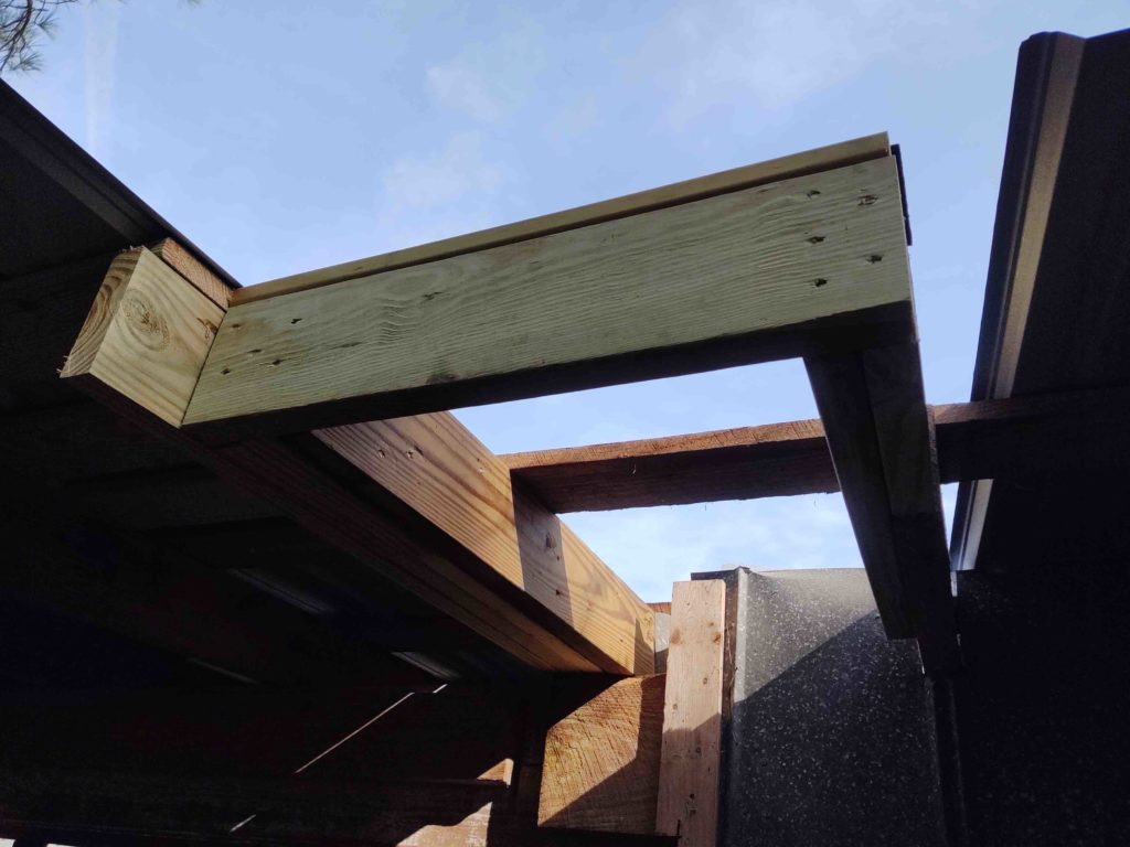
Of course I wasn’t too concerned with the old roof, but with the new roof I don’t want to tear up the panel that I’ll have my ladder leaned up against. So once I figured out the exact placement of the first non-carport panel (covering actual workshop), I extended the joists on each side, framed in a back plate for the ladder to lean against, and also a small top cross purlin for extra support.
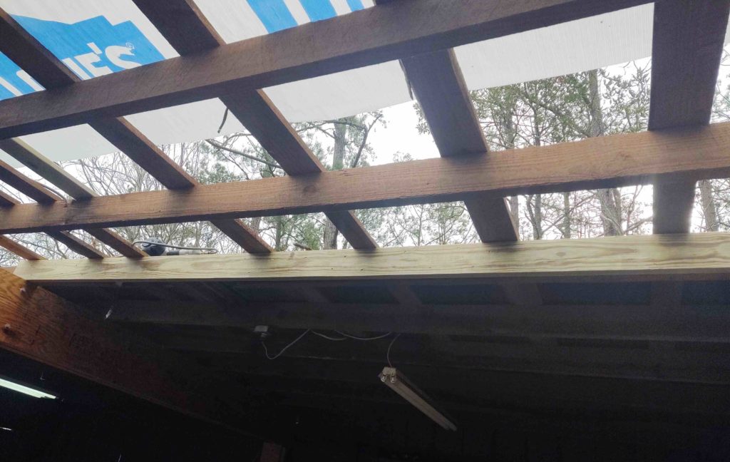
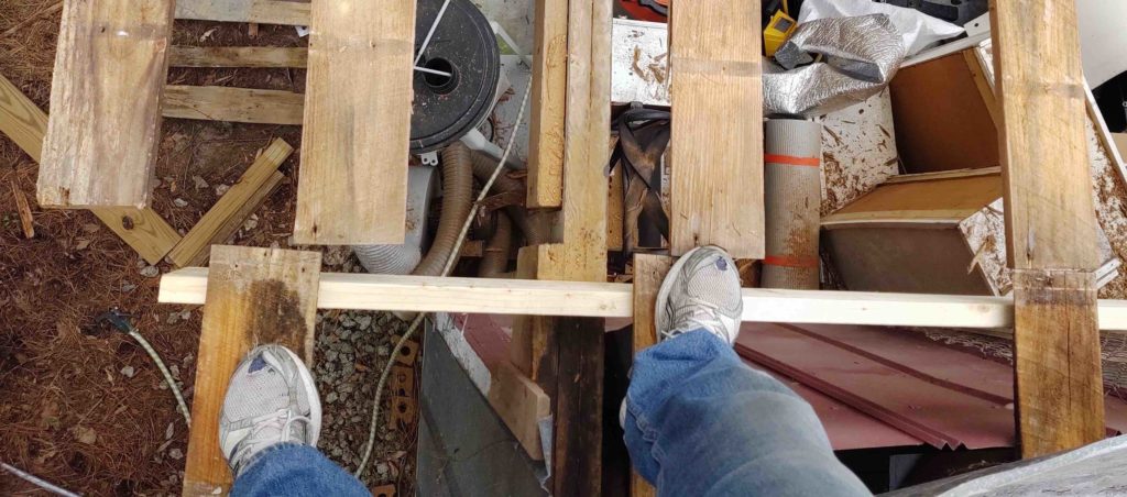
From below, here’s the new ladder leaning spot for roof access.
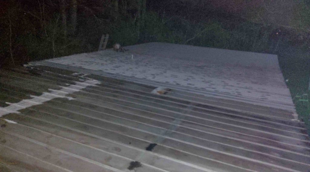
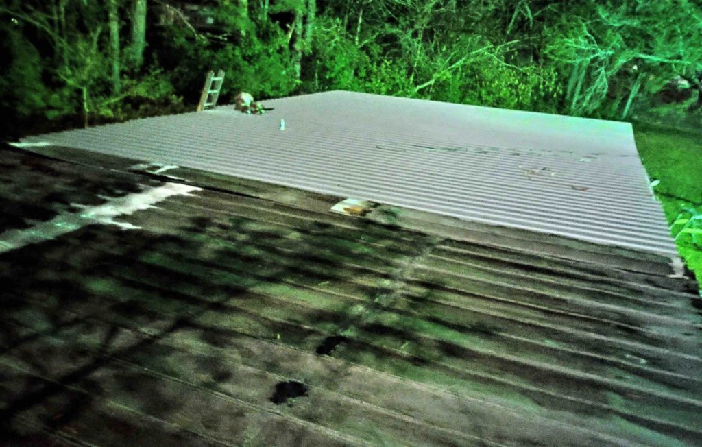
After I attached the 3 new panels I then got to work removing 4 more rows (front to back) of the old roofing, for a total of 9 rows (18′) of old roofing removed between yesterday and today.
Just as yesterday, it was too dark and too late to screw the panels into place, so I set them in place and then covered up the remaining small gap between old and new roof with 3 of the old panels overlapping each other back to front.
Unlike the period between yesterday and today, which saw clear weather, it is supposed to rain in the pre-dawn hours tomorrow up until about 10am. Hopefully the panels set in place will work well enough to keep the rain out of the workshop until I can permanently secure them.
Again, the roof replacement is a long hard slog, but I’m definitely over the hump. And after I get these panels screwed into place will only have 8 more left to install (24′ more in width).
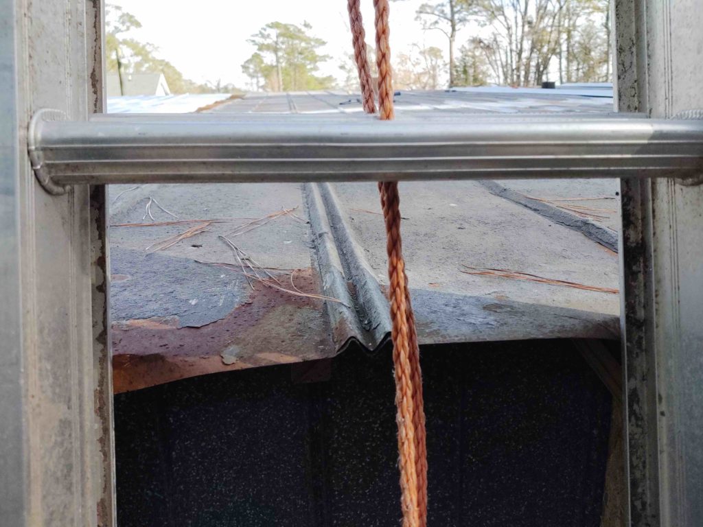
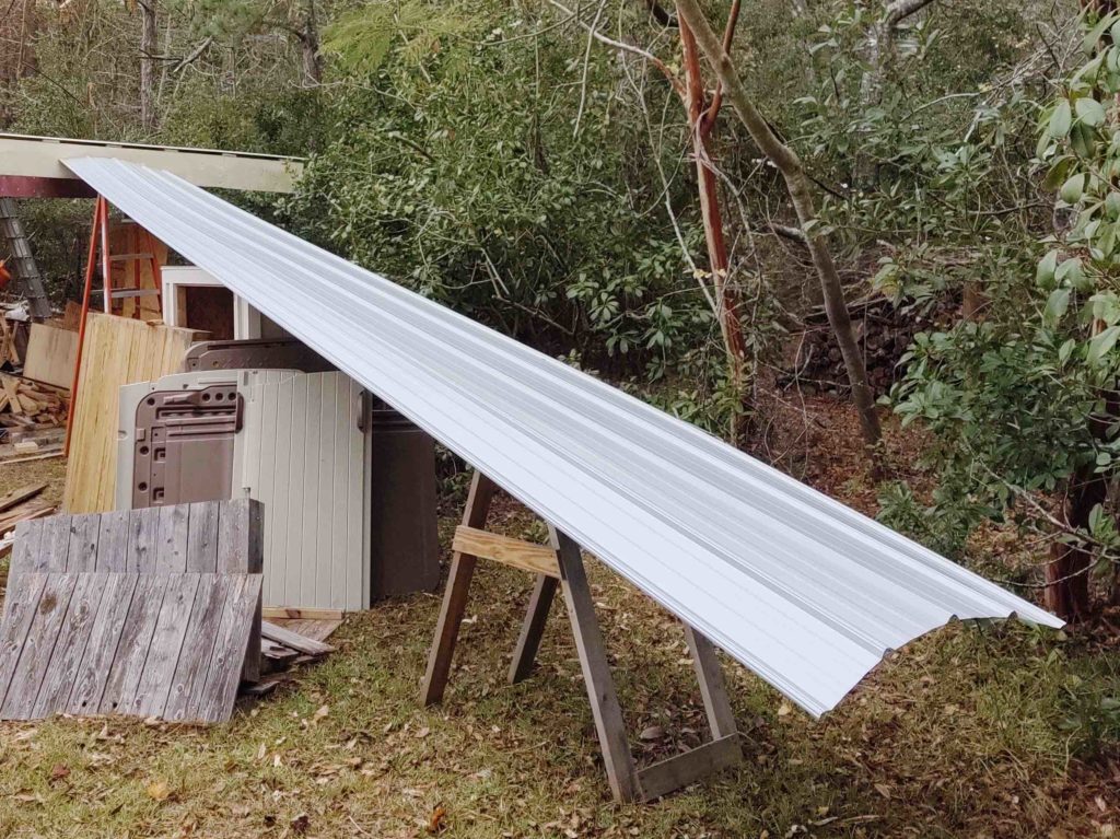
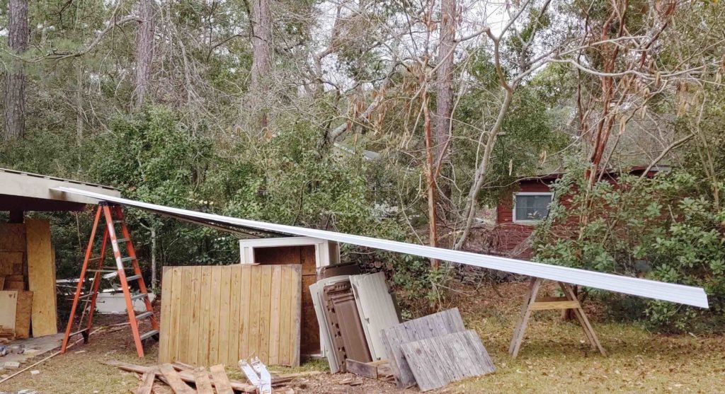
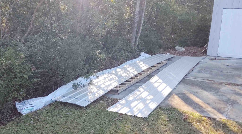
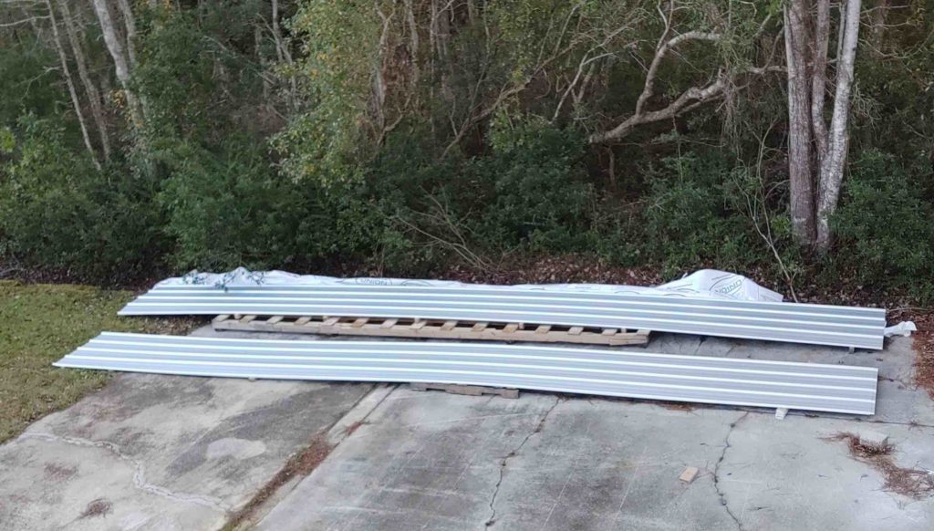
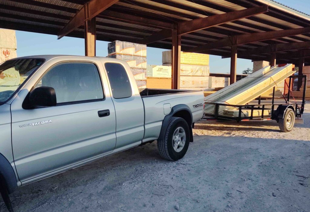
I grabbed a couple shots of my improvised ramp which is the MAGIC of my getting these 30′ long panels up onto the roof without any unwanted crimps in the panel surfaces… by myself!
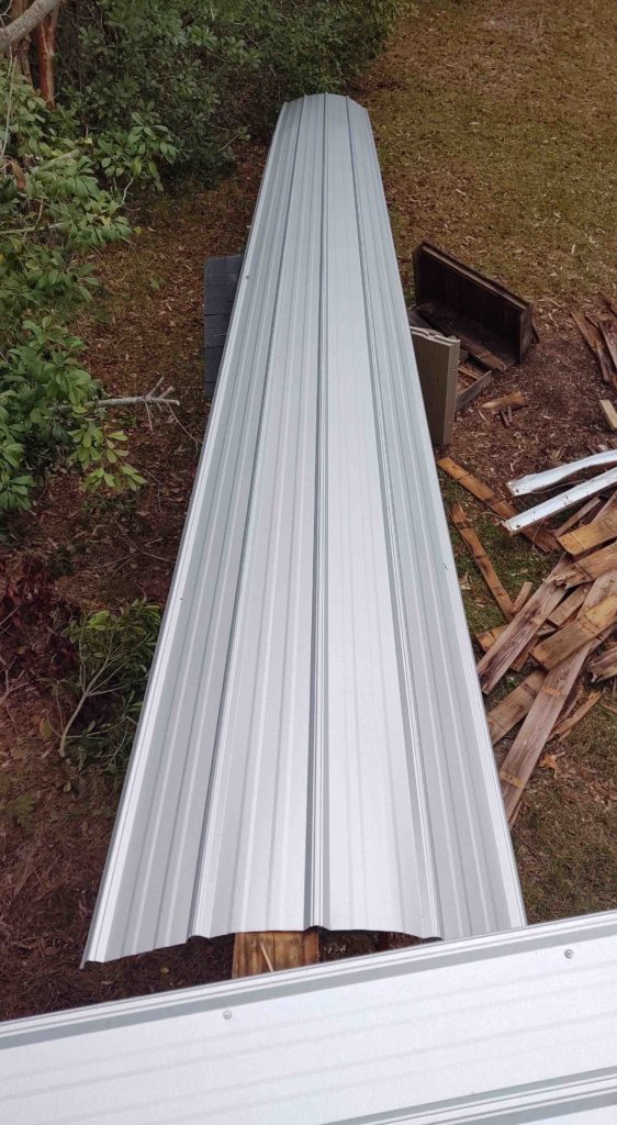
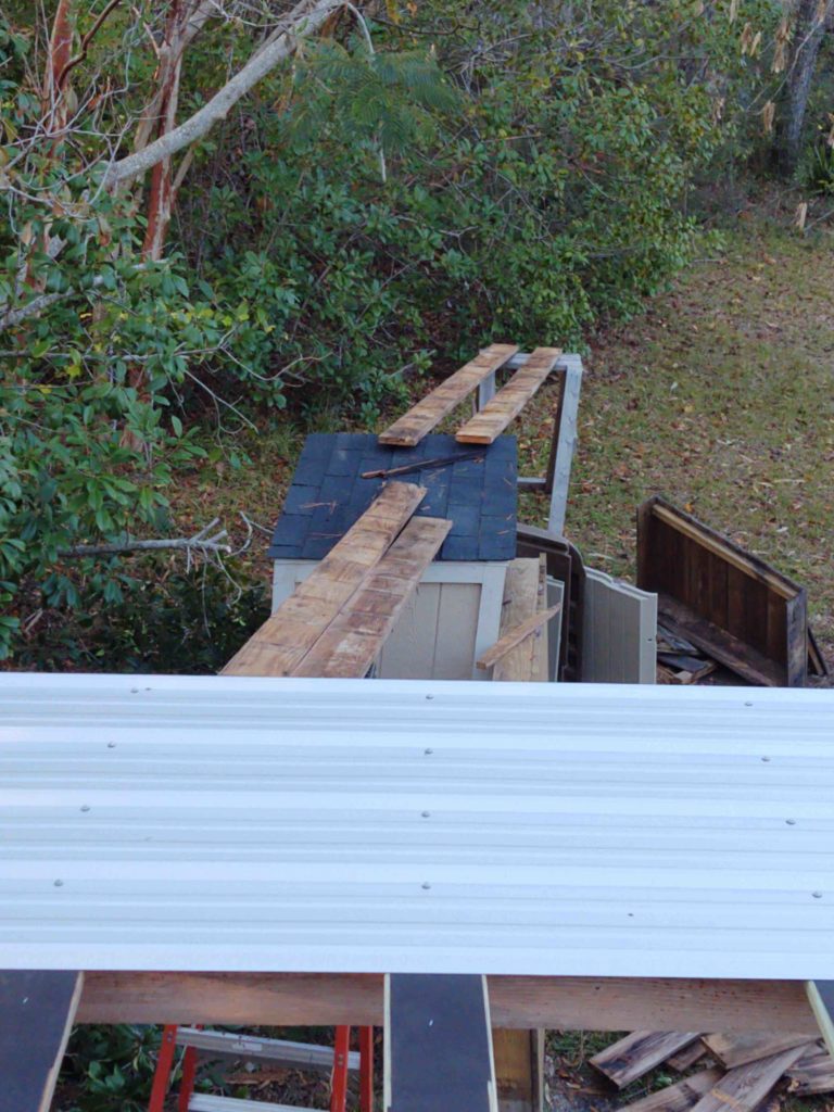
And here we have a shot from the roof, with the panel in position to come aboard! . . .
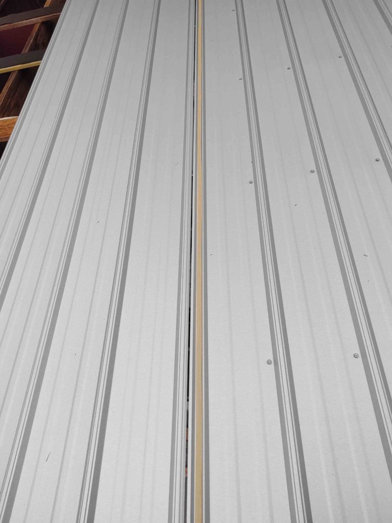
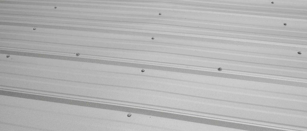
As I explained previously, since my workshop doesn’t have the requisite minimum slope of 3″ on 12″, I’m required to tape the seams with a 3/8″ double-sided butyl rubber tape (super sticky) and then screw the seams to each other.
As an example, the two screws on top of the raised crown of the seam (below) are what’s used to compress the panel edges –and thus butyl rubber tape– together to provide much more watertight seams.
So enough with a pedantic discussion of my metal roof. The big news is that I was able to finish installing the 8 panels that make up the roof of the overhang/carport.
This puts me at over a third of the way done on reroofing the workshop. Actually a little more since I really don’t think I’ll need to replace nearly the number of purlins that I did on the exterior overhang.
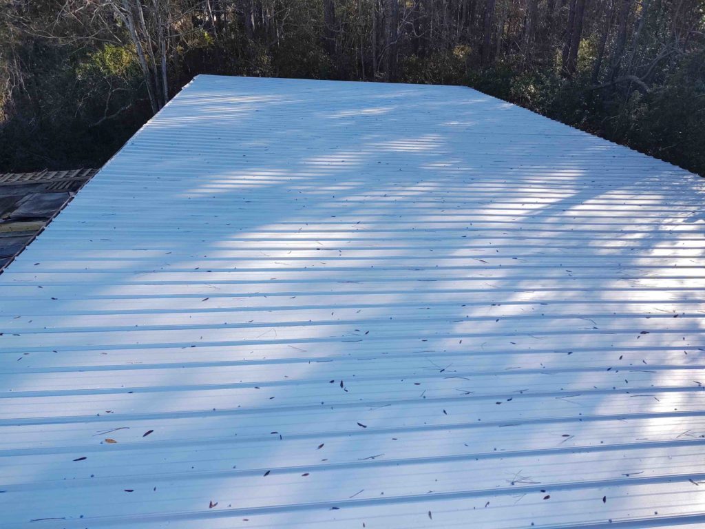
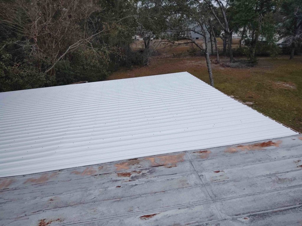
Here we have the aft side of the finished carport roof. You can see in the pics how the new roof compares to the old, rusted nasty one…
Again, the weather forecast for the next week is for a lot of rain. I will try to squeeze in as much as I can on getting the rest of the roof knocked out, but the weather will certainly dictate my progress.
Not surprisingly, folks may think I’m being a bit anal about the roof install and doing too much… at least per the few comments I’ve received from some friends. All non-airplane builders mind you <grin>.
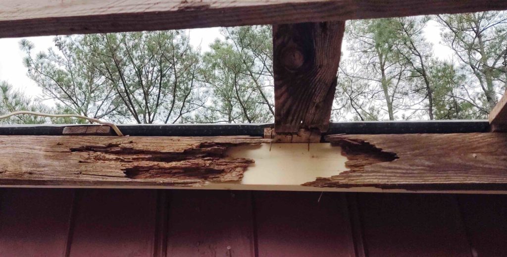
But here are just a couple of examples of the wood rot I was dealing with on the purlins to which the old roof panels were attached. With nothing to hold the roof panels’ attaching screws or nails, then the rubber gaskets had no pressing force to seal out the water. Over time the retaining hardware became nothing more than a conduit for the water to follow down through the panels to simply leak out underneath onto whatever was below (currently, the stuff I had stored in the hangar!).
On the intersecting wall between the exterior right side of the shop and the exterior overhang (“carport”) there was wood rot just as serious. This rotting ledger board was half-heartedly hidden by a 2×4 that was serving as a roof joist, that itself was not doing so well. All had to come out…
Yes, would have preferred to rip out the non-treated board but it ran all the way forward to the carport’s midpoint beam and intersected with the forward joist. Just too difficult to extricate so I reluctantly left it in place and built over it. At least it was in good shape with no evidence of wood rot… or dry rot for that matter.
Here we have the old rotting ledger board and pathetic 2×4 “joist” replaced with pressure treated lumber. I could then move forward since I had something with structural integrity to attach the inboard edges of the top purlins to.
Here’s the purlin replacement progress on the forward half of the roof at the end of day 3 of the roof replacement push.
And the purlin replacement on the back half of the roof, about day 4.
Day 5 (today) I was finally able to get the purlins covered with strips of roofing felt since the Galvalum panels must not be mounted directly to pressure treated lumber. The ensuing reaction between the treated lumber and roof panels would not be pretty and significant corroding with show up at those spots within just a few years, if not sooner.
The 8 roofing panels that get installed on the overhang/carport roof section are a foot longer than the 14 panels that go on the workshop section of the roof. Of course on the pallet of roofing panels they delivered, the shorter sections were on top so I spent a good half hour removing & restacking the shorter panels to gain access to the longer ones.
I did a full frontal assault for the first panel, using way too much energy and consternation to get the first roof panel in place coming in from the front side of the roof, which is significantly higher than the aft side…
Nonetheless, I got the panel up there and then attached that baby… after a good 30 minutes of measuring and minute adjustments to make sure this “cornerstone” panel was set correctly.
For subsequent panels I wanted to reduce the pain and effort to get one of these mammoth panels up on the roof… so I went the Masada route and assembled an extended makeshift ramp.
Still a bit tricky, but panels 2 and 3 went up on the roof MUCH easier than the first one… live and learn, eh?!
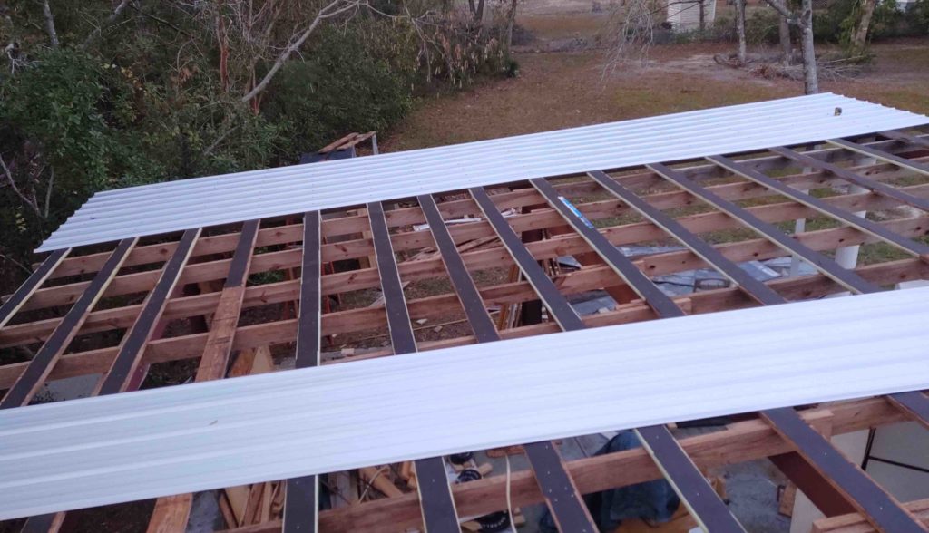
Here’s panel #2 installed with panel #3 awaiting its turn.
It was full-on dark when I took this pic below, and I was actually using my phone’s flashlight to finish up installing the screws on panel #3 . . . but it’s installed!
Tomorrow is Sunday, and Monday there is forecasted rain in the morning. Thus, I will be going all out tomorrow to get the remaining 5 panels installed on the overhang/carport section of the workshop roof. I SHOULD be able to get it done before it gets too dark.
A quick update here on the workshop progress over the last 2 days… still a decently long slog underway.
The weather has been and is forecasted to be cool but sunny for the next few more days. Then single days of forecasted good weather interspersed with rainy days. So I’m trying to get this roof knocked out as quickly as possible. The problem is that the days are SO short, and I run out of daylight at 5pm now.
So, here we go. Here’s the first panel off. The roof currently has 3 overlapping rows of panels, with each panel 2 feet wide. I’m replacing with 30′ long single panels –no overlaps from front to back– and 3 feet wide panels. Clearly fewer seams so less chance of water making it through. Since the pitch is much less than it should be for good rain runoff, I have to use a narrow strip of double-sided Butyl tape and screws every 24″ on the long seams.
Here you can see the 3 rows of panels, and I have the first couple of front-to-back strips (“columns”) removed here
I had planned on removing two of the 2′ front-to-back strips and with the 4′ width exposed then install a 3′ wide section. Remove and add across the roof….
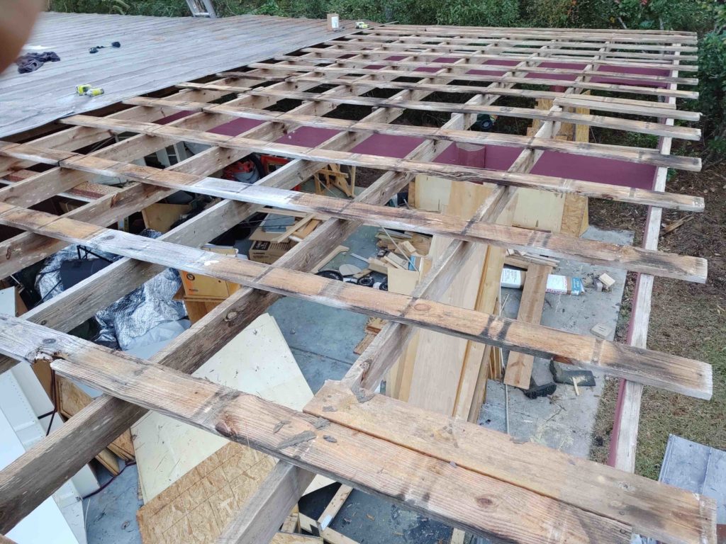
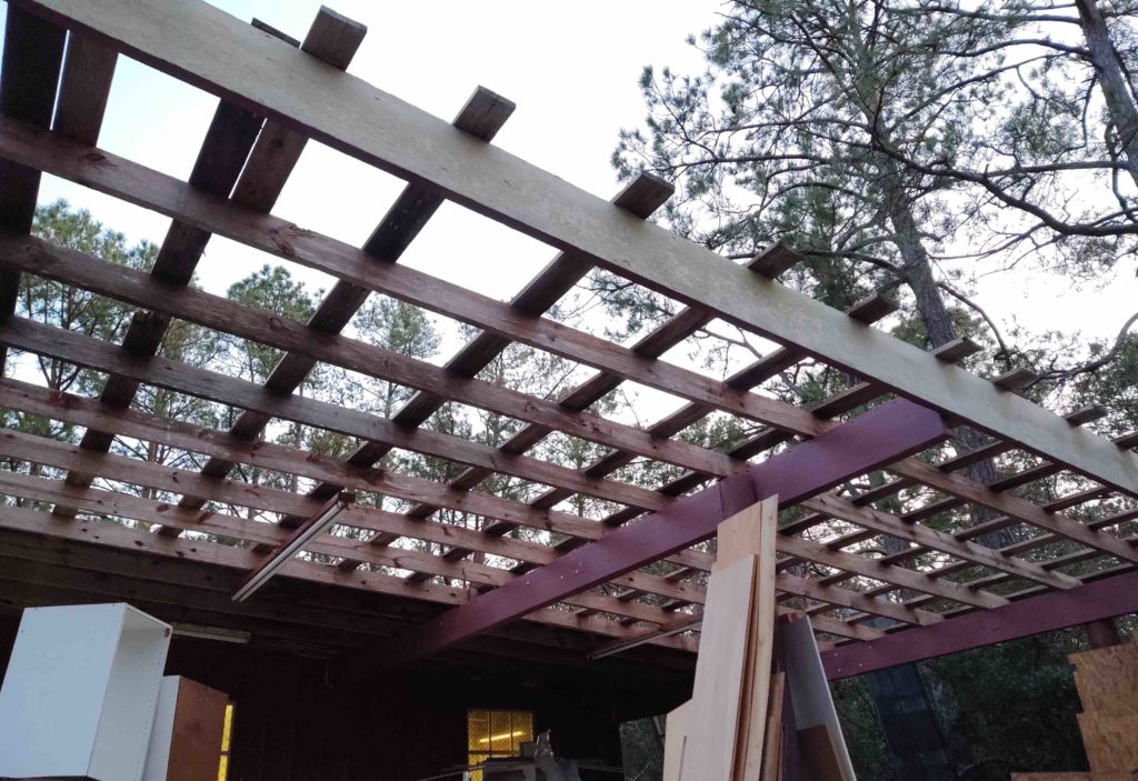
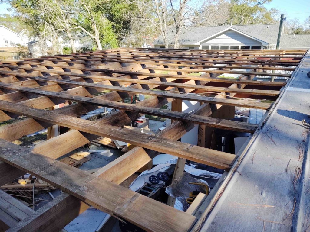
Unfortunately, so many of the cross purlins boards are in such bad shape that I have to replace somewhere around 45-50% of them (still assessing). So I changed my plan and simply ripped off all the panels above the overhang/”carport.”
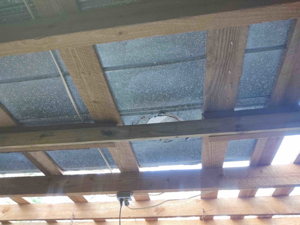
If you look closely at the purlins in the middle area, next to the existing metal panels, you’ll see they’ve almost entirely rotted through.
Here’s a shot from below… btw, those purlins are 1x6s, which gives some perspective on the size of this roof.
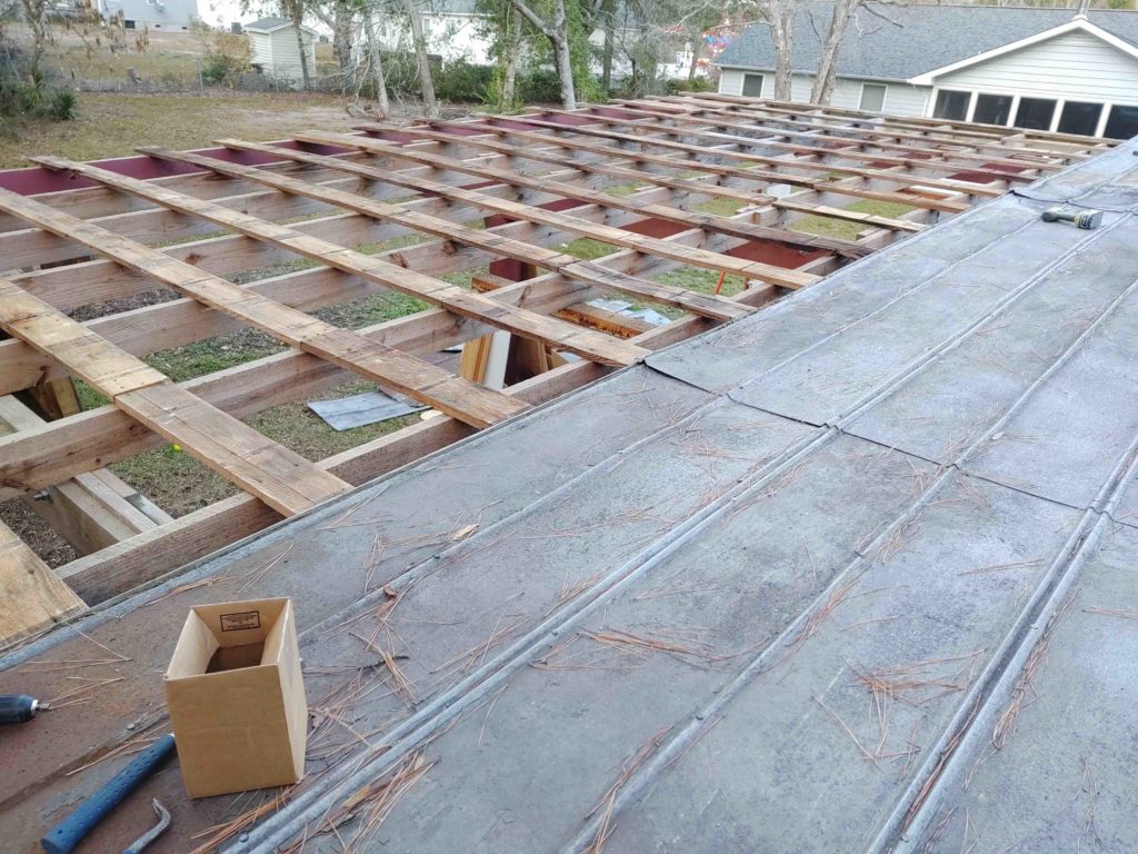
Here we have a couple shots of the entire overhang area, or “carport,” deroofed.
I then had to run down to a local builder supply to pick up a ton more wood than I had expected to for replacing primarily the purlins, and even adding to about 10% of the underlying joists to bolster them for strength. I will say that I’m definitely getting my money’s worth out of this utility trailer!
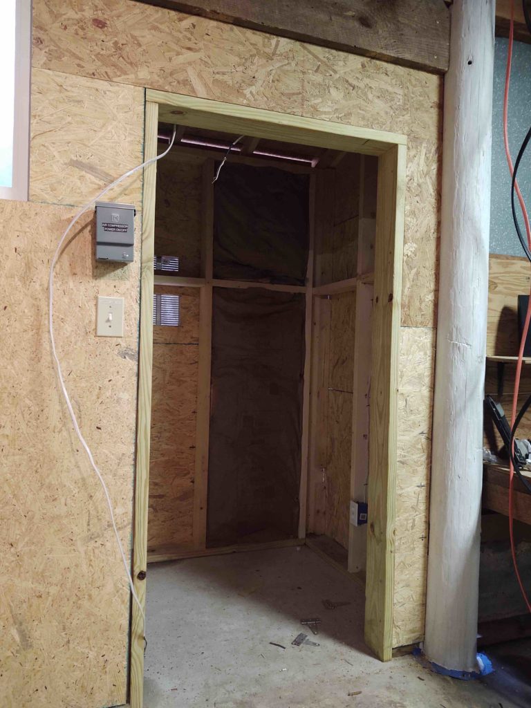
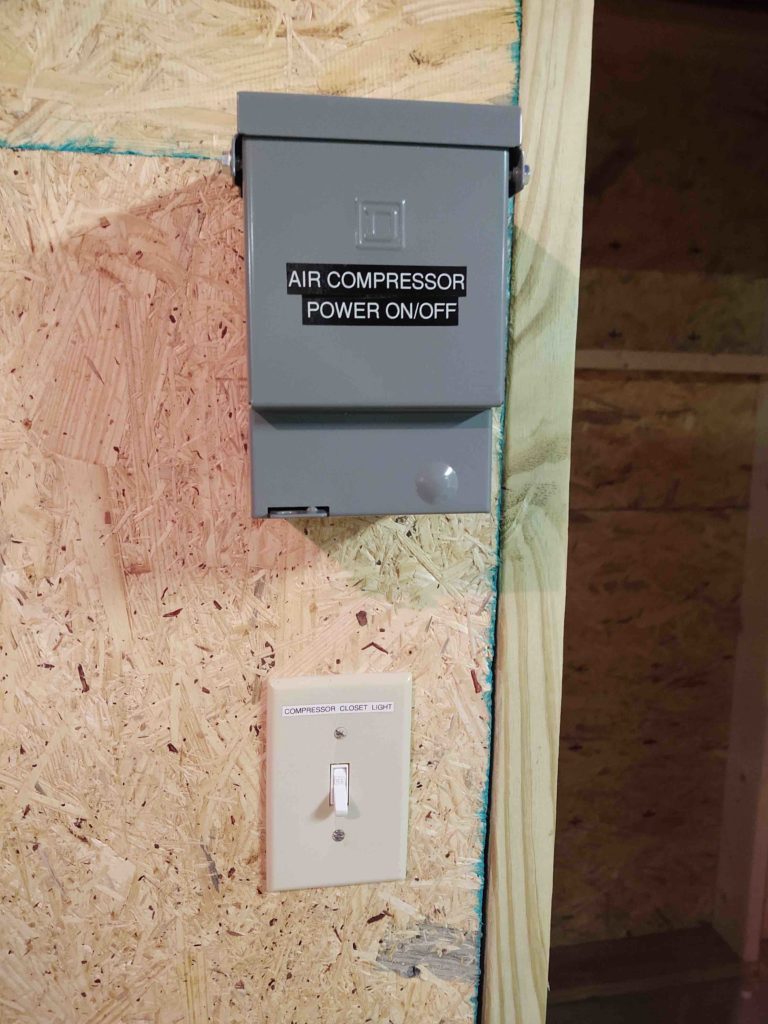
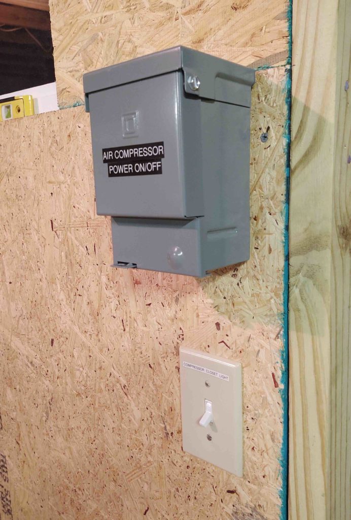
Again, since it gets dark so early and I can no longer work on the roof, I took the opportunity on evening #1 to wire up the 60 amp air compressor on/off switch. This switch will allow me to turn the air compressor off & on without having to open up the heavily insulated compressor closet door and reach into the flip the switch on the actual compressor.
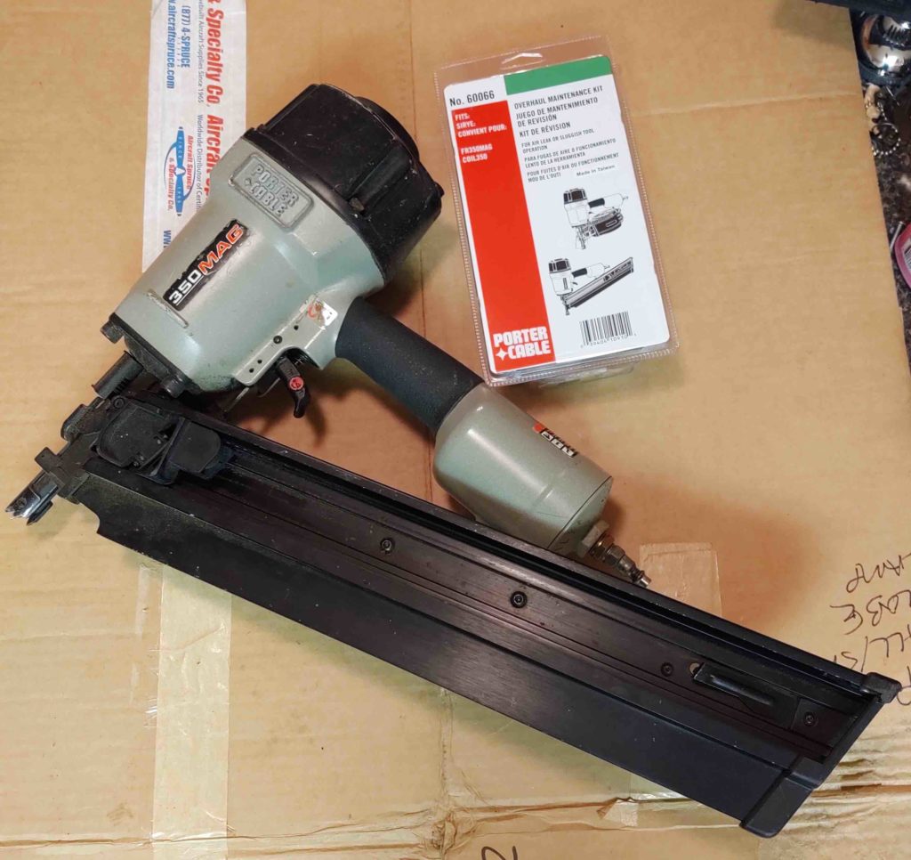
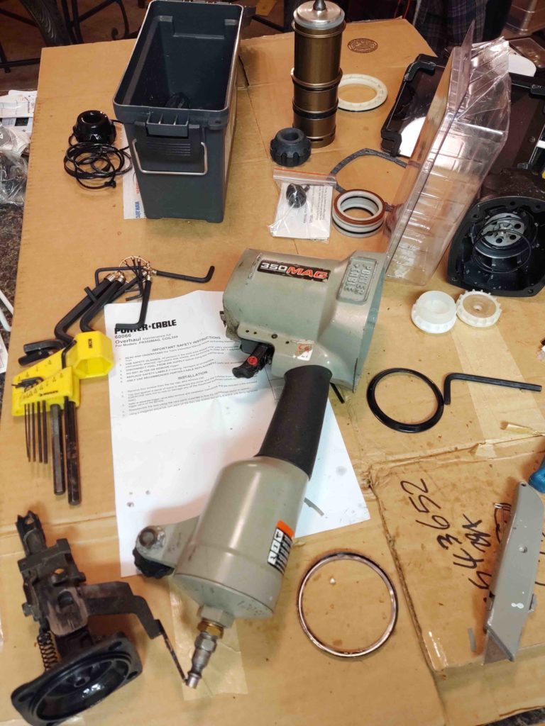
On evening #2 (tonight) I finally got around to opening up my not so cheap (over $100) framing nail gun refurbishment kit since my framer nailer is currently leaking air and inop.
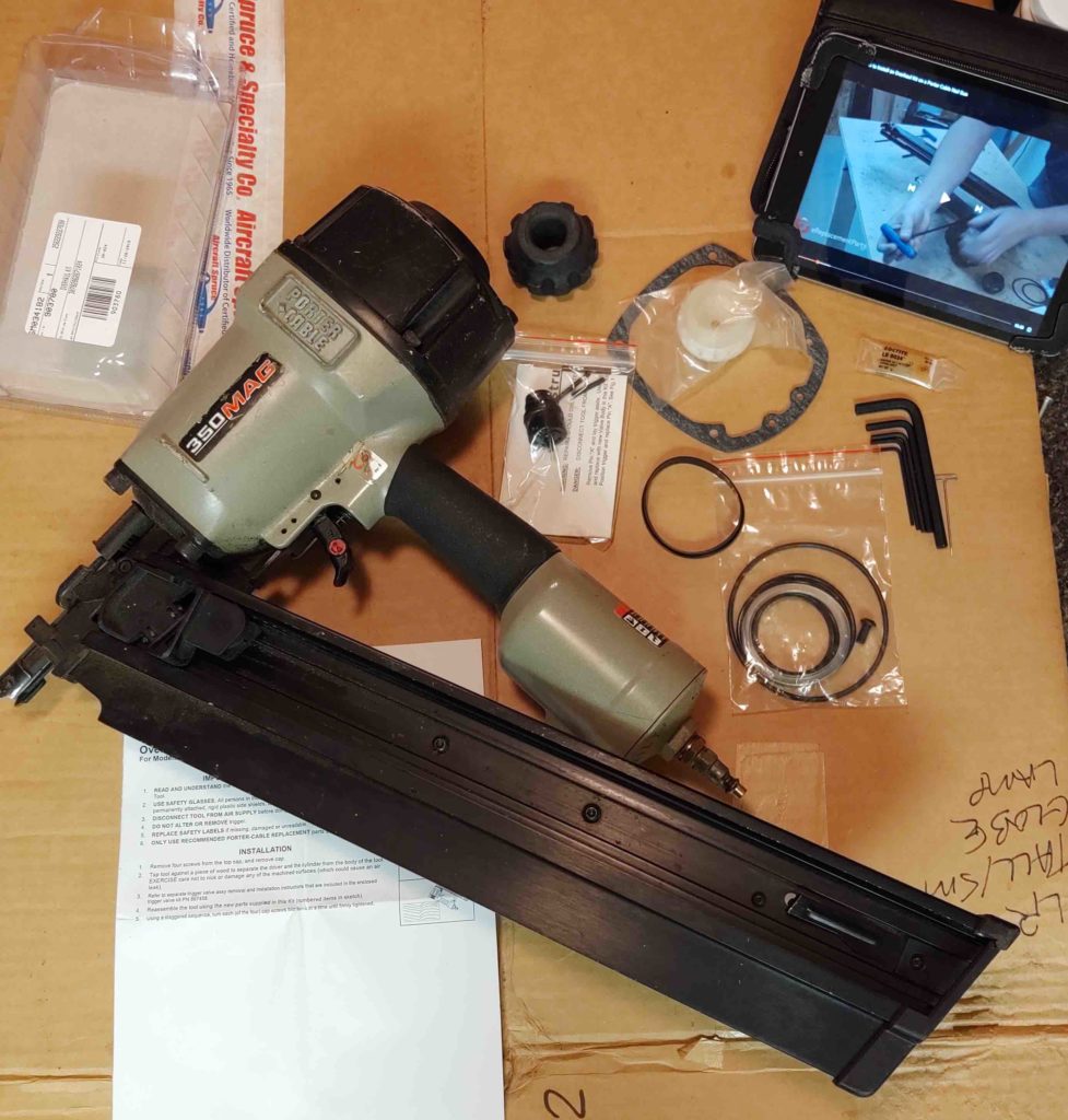
In the left pic below we have the parts from the refurb kit out of the box for inventory. Also included for required tools on hand is my iPad with the requisite how-to video on refurbishing the nail gun. The model the guy covered was a Porter Cable nail gun, just not mine… but definitely close enough to get the job done.
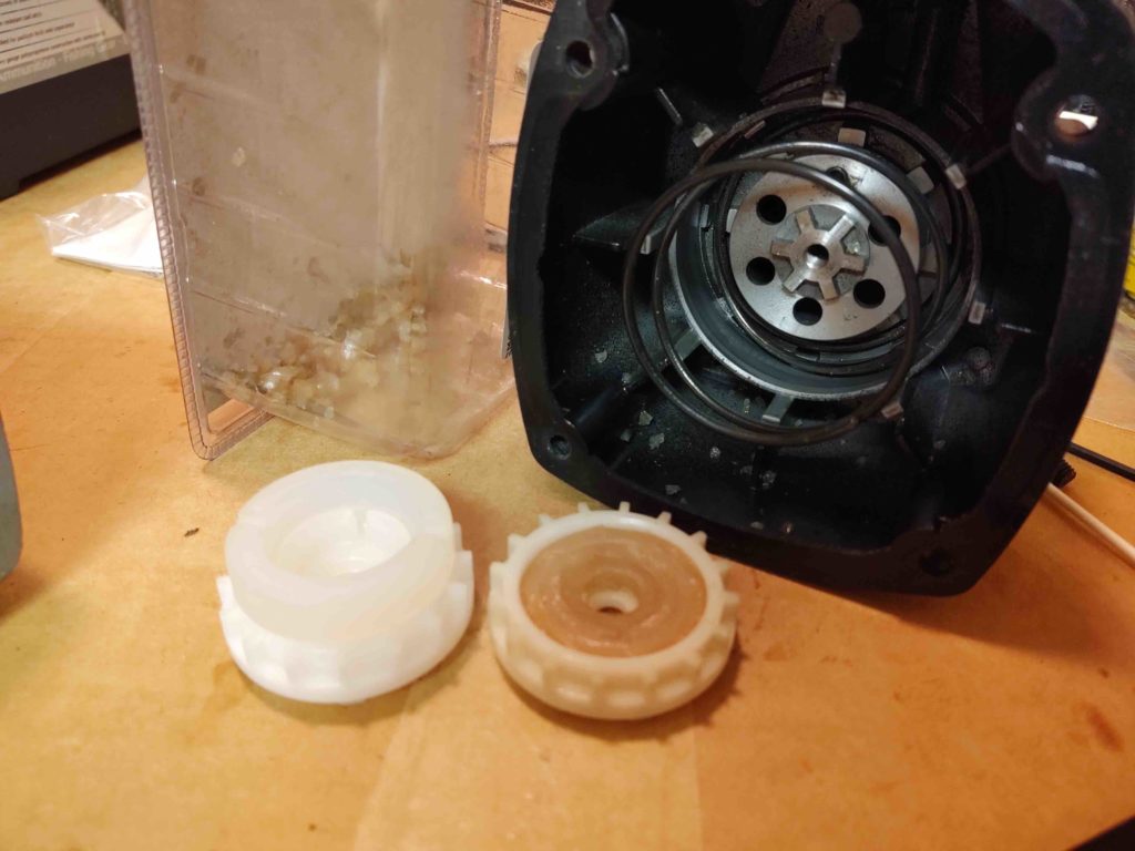
The pic on the right shows what the problem was… besides just being old and worn (I bought the nail gun off of eBay for a good price, and have used the piss out of it since… so not surprising it needed some TLC after all these years) the air valve literally just came apart into a gazillion pieces, and looked like somebody had poured a cup full of rock salt inside my air gun. The old air valve is on the right, but should like the new one on the left. Note in the background all the pieces of the air valve both in the top gun housing and in the refurb kit plastic package where I started collecting these myriad of pieces. Moreover, the inside of the gun is soaked in lubricating oil, so these pieces stick wherever they happened to be…. meaning I had to physically remove every minute piece of plastic.
Here’s my framing nailer broken down to about as far as it can be. I did actually remove the trigger and swap out the trigger valve for a new one as well.
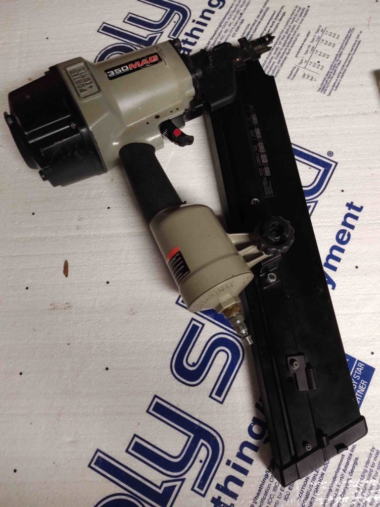
After a couple of hours (mainly cleaning out all the plastic bits) I put ‘er all back together and took it out to the shop for a test fire. It was leaking around the top gasket so I really had to gorilla the top bolts SUPER tight (which they were when I removed them) and that did the trick.
So my framing nailer is back online, and just in time too because I’m gonna need this guy big time for nailing in all the new replacement purlins.
Thought I’d provide an interlude to the myriad of shop upgrade posts I’ve been making to have a discussion on the whole purpose of upgrading the shop in the first place: my Long-EZ build!
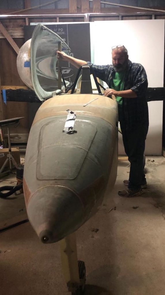
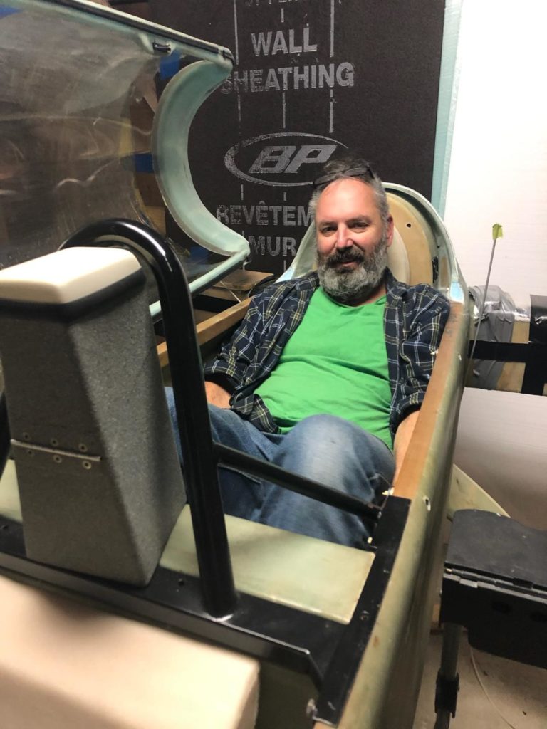
First off, Stacey was here visiting from Greensboro over the Thanksgiving holiday, and while she was here I definitely wanted to have her try out the Oregon Aero back seat cores. If I had been thinking I would have grabbed some selfies of both of us in the bird, me in front and her in the back seat, but alas I wasn’t.
Stacey –being a professional photographer– was thinking and she grabbed some pics of me messing about with the plane. Here I am at the start of our seat testing venture opening up the canopy . . .
And then apparently thinking of all the shop tasks I have to do before I get back to building… only reason I can think of for looking so annoyed. Ha!
And below I was enjoying how nice the seat cores feel!
On a serious, note: I’m 5’11” . . . or maybe just a hair under that now. The law of unintended consequences reared its head as I was testing out the GIB seat cores. I realized that with the thigh support sumps built in, there’s only so far down you can go before you hit that hard stop.
You see, in the original Long-EZ you were sitting on a simple sloped seat… kind of like a banana shape. If you were taller you could merely scooch your behind lower/forward, bend your knees a bit more and get your head lower into the canopy. Again, with a “hard stop” literally keeping your butt from sliding lower into the airplane, it makes for a height restriction at just about my height (not planned btw). Sitting normally I have about an inch or two to spare above my head with the canopy closed.
So, at my height sitting on the thigh support has me in a more upright position than in a normal (stock) Long-EZ. This naturally puts my shoulders higher and thus more in between the longerons vs. underneath the longerons. You can still game the system in my back seat by scooching your behind further forward ON TOP of the thigh support, but this leaves an open air gap under your lower back. Ironically, I think I may need to have a small lumber pad to put in place for my taller pax!
Moving on . . .
A few days ago I was part of a 3-way FaceBook message going on between Mike Beasley, Marco and myself. I was working on the shop so was in total lurk mode as Mike and Marco discussed Mike’s placement of his autopilot pitch servo. At the start, Mike was considering putting it just forward of the stick at the base of the instrument panel. Marco adroitly pointed out that when he installed his AP pitch servo that it messed with his Whiskey Compass big time, and was the reason why he mounted the servo as reasonably far away from the panel as possible (just aft of the front seat).
Mike played around with Marco’s proposed pitch servo location and eventually made it fit… good for Mike and collaboration worked to save the day again.
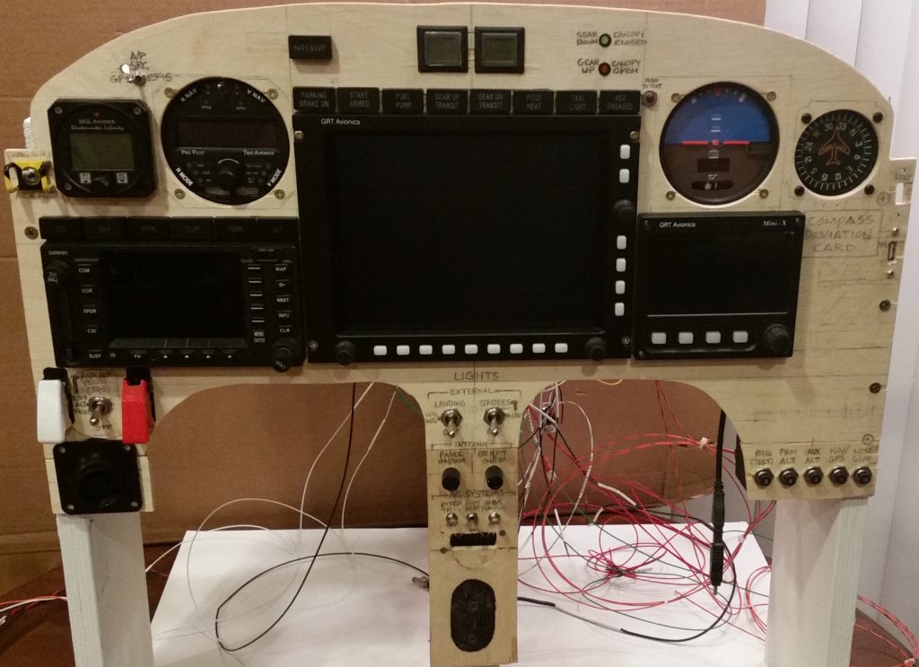
However, this got me to thinking seriously about my Vertical Card Compass and it’s relatively close quarters with my AP pitch servo not even a foot’s distance away. Yep, my compass is stuffed in the upper right hand corner of the panel and the pitch servo is mounted forward of that on the right side wall.
This potential issue got me researching and resulted in a phone call to Trio Avionics to confer with Jerry and Chuck on the matter. I learned that the Trio autopilot servos are primarily made of aluminum, with some plastic in the mix as well… which may be different than GRT or Dynon AP servos. Moreover, both Chuck and Jerry fly Long-EZs with both Trio autopilots AND vertical card compasses mounted in their respective panels, and neither of them have had issues with negative servo influences on their compasses.
They did however of course recommend that I install both compass and pitch servo and test out my configuration. That being said, I’m fully expecting to have to mount the compass in the upper left hand corner in a swap-out with my MGL clock/timer.
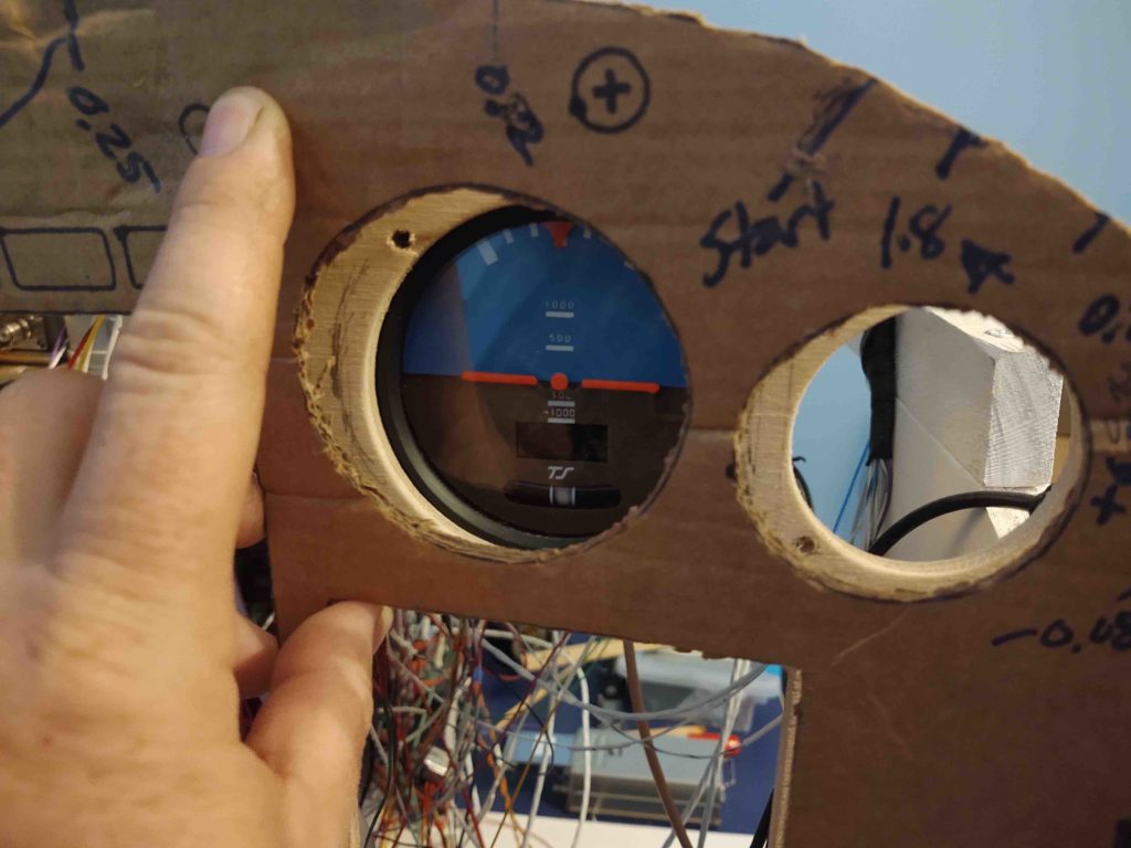
As I was assessing the probable position swap of my clock/timer and compass to opposite sides, I noted the minimal amount of space I had for anything in the upper right corner of the panel. It was then that I remembered that after making the decision to mount the Trig TT22 transponder in the right outboard strake, that I had moved the panel positions of both the TruTrak ADI and the Vertical Card Compass inboard about 1/4″. I grabbed an older (not the latest) cardboard panel to test if I was remembering correctly: Yep, I was.
I then spent the next couple of days –when I had a moment to think– pondering my courses of action. First, I could easily just move the TruTrak ADI and the Vertical Card Compass back outboard to their original positions. But to be honest, I like the better symmetry of these instruments’ new positions and don’t want to change that.
Then, upon further inspection it appeared that the real problem for fitting the Trig TT22 transponder was the GRT serial adapter. I then considered making up a 25-pin DSub to 25-pin DSub cable to allow the serial adapter to be placed somewhere other than on the front jack physically connected to the transponder unit. But that would require A LOT of work and a good bit of money for all those D-Sub connectors.
Thus, my final course of action and the solution I plan to go with will be to simply build and install a 90° bracket to allow the Trig TT22 transponder unit to be mounted on the right side of the TriParagon’s top shelf. I still have to check final clearances, but so far this is my plan. In addition, if I ever swap out my TruTrak ADI in the future, the screw pattern I’ll use for the bracket mount to the top shelf will be the same as the transponder bracket… allowing me to mount the transponder unit back in place on the top shelf whenever space allows.
Don’t go anywhere… there’s more!
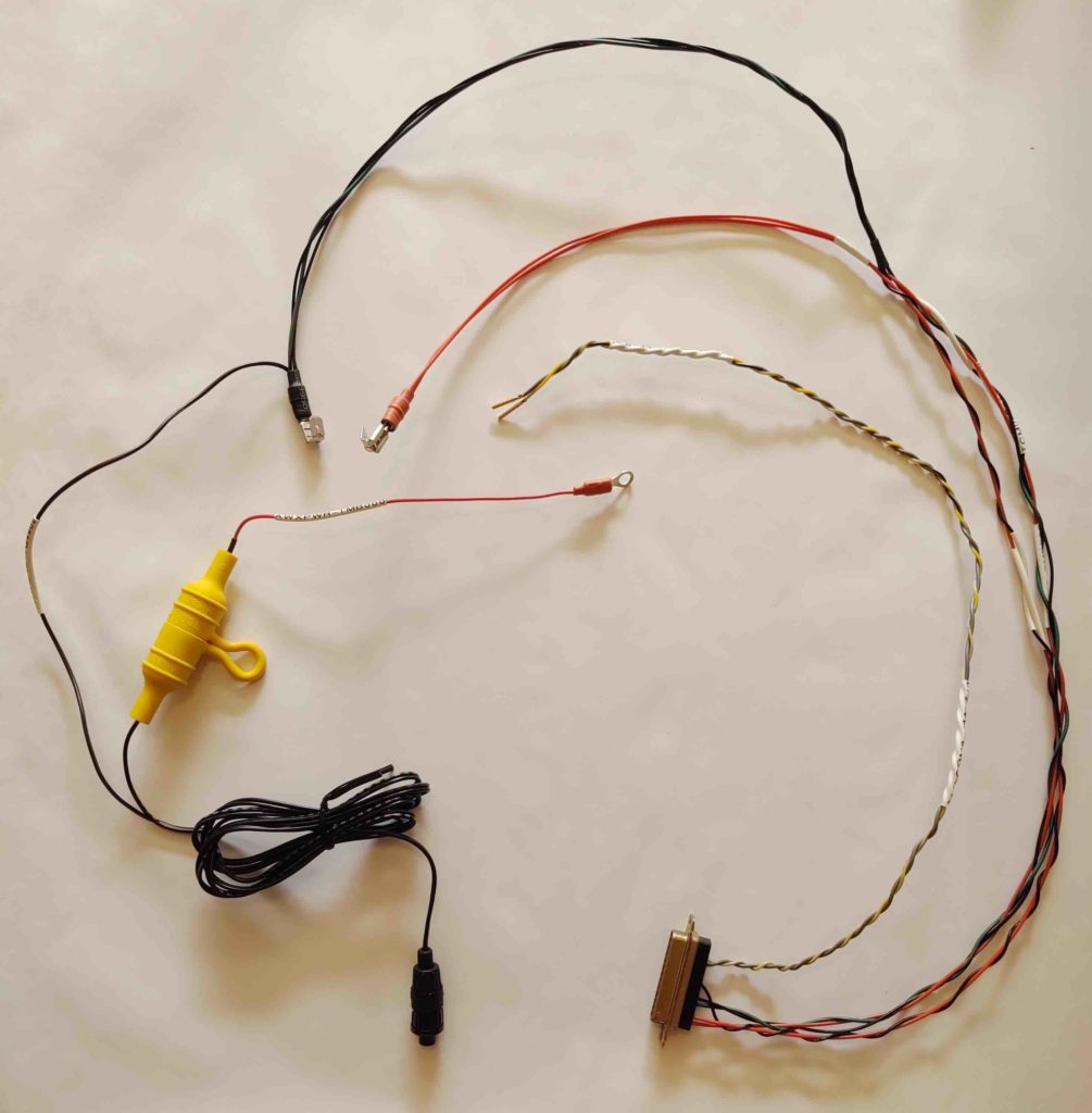
Over the past few days I’ve also been locating and collecting up all my tools, gadgets and consumables to allow me to build the wiring harness for the Trig TY91 COM2 radio (minus the 4 wires to the intercom). This will allow me to fire up the TY91 and have it connected to the GRT HXr EFIS so I can configure the COM2 control functions.
In addition to instituting a major switchology reconfiguration and doing a bunch of wiring diagram updates, I’ve also been taking a hard look at my ground busses and scrubbing those to make room for all the connections. I mention this because below is the WxWorx box power connections (left) included with the Trig TY91 COM2 harness (right). You may note that the ground wires of each component are combined together in, again, an effort to optimize my ground buss connections.
Over the next few days I will try to get my panel mockup repopulated and specifically the Trig TY91 COM2 radio connected and configured for control via the HXr EFIS. In addition, I do plan on firing up the WxWork system (although I don’t have a wx data subscription yet) to test out the Bluetooth connection with the Bendix/King AV8OR GPS unit.
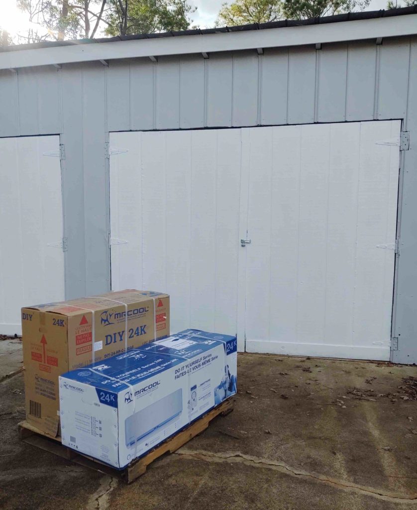
I ran around this morning to pick up more supplies and then returned home as I awaited the delivery of my mini-split HVAC system… which arrived mid-afternoon.
I then stowed it away in the work shop and ran out to get even more supplies, including more OSB sheeting for the next segment of wall that I intended on insulating and covering.
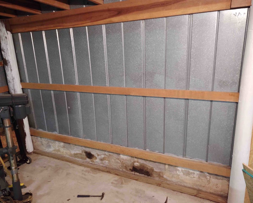
My first task was to remove all the nails and an entire row of wire hooks installed on the top board, with many of them having ropes hanging down off of them.
And yes, the stains look pretty nasty on the lower portion of the walls. I’m not sure what material they used, but it seems to be holding up well even though they all look terrible… and as a point of note it’s not mold.
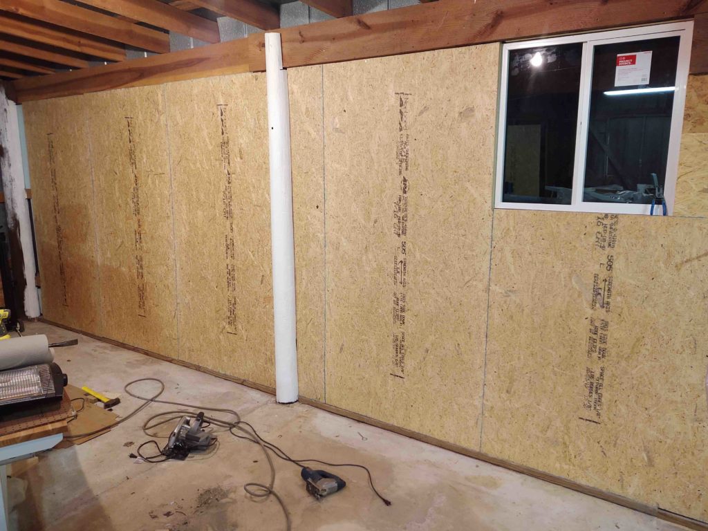
I then cut the 2″ thick foam pieces and inserted them in-between the wall purlins (boards). After the insulation was in place I simply installed three 4×8′ OSB panels in a row. I still have the very corner strip to finish, but this was a good stopping point for the evening . . . except…
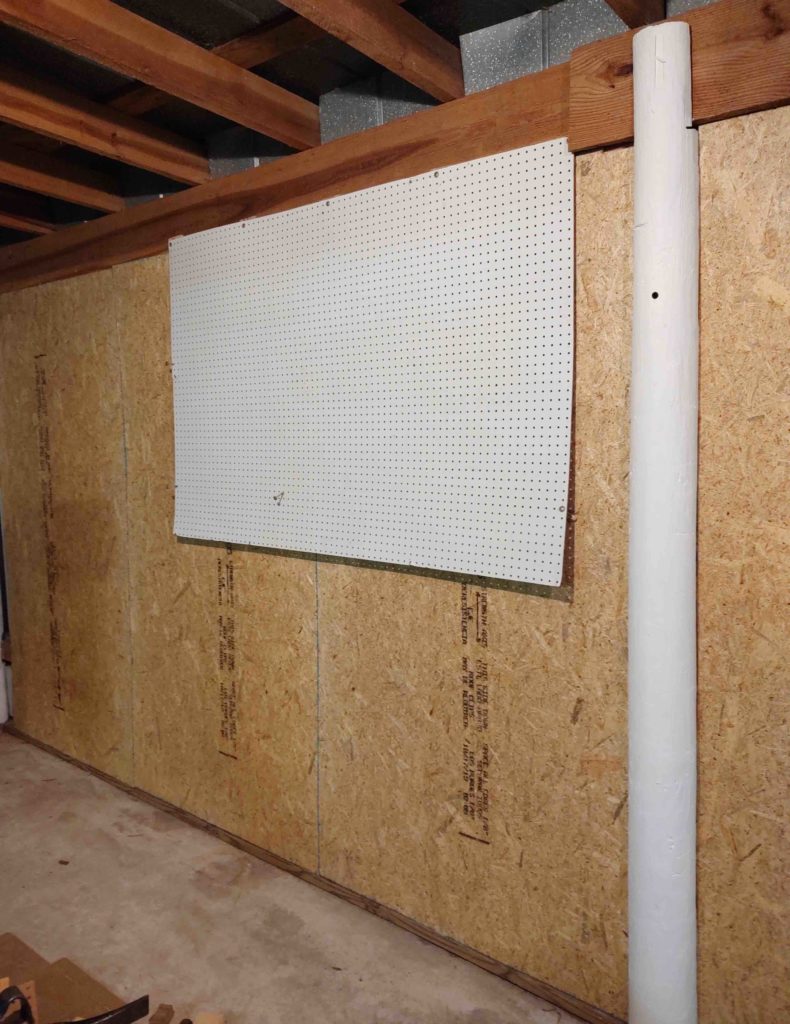
I then spent a good 30 minutes prepping and then mounting my peg board —which survived the tornado, but looked like a pretzel when I found it in the hangar— on the wall. Actually, I only ensured it was level and then mounted just the top screws. I’ll get the lower screws installed later.
If the weather is good tomorrow I’ll spend a good amount of time prepping and then start on replacing the workshop roof panels. Once the roof is done (as much as I can do over the next few days…to a week) I’ll get back to installing the mini-split HVAC system and then the air compressor.