Chapter 22 – Low Hanging Fruit

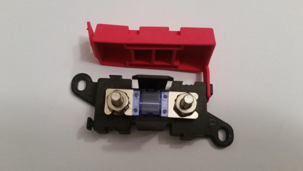
Today I started off by printing off 3 batches of electrical wire labels, which included the label for the large (12 AWG) power feed wire from the SD-8 backup alternator-to-E-Bus control relay (RL018) to the mini-ANL15 current limiter (fancy name for “fuse”, IF010).

After heat shrinking the label in place, I then re-terminated the wire with a ring connector vs the previous FastOn connector I removed.
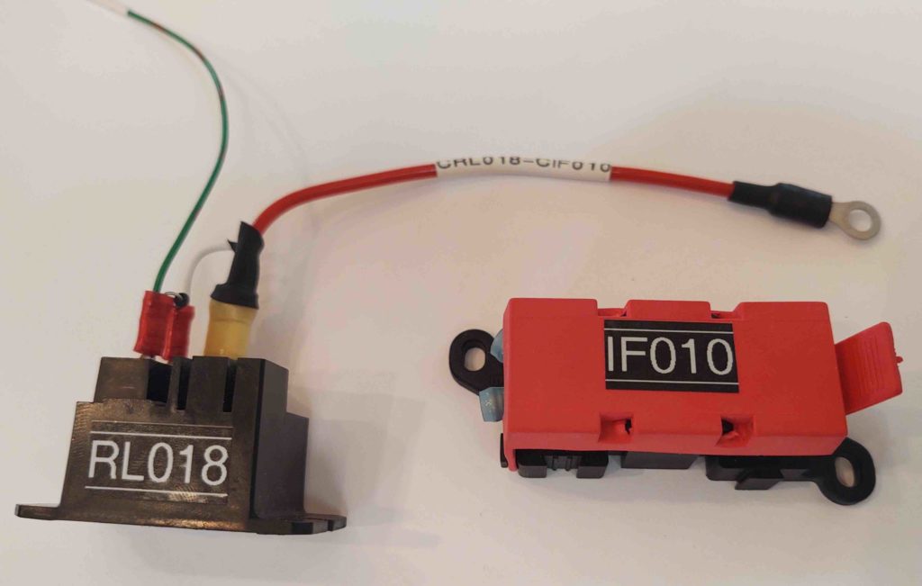
I then connected the wire to the ANL15.
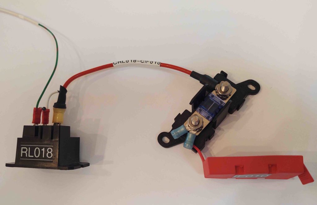
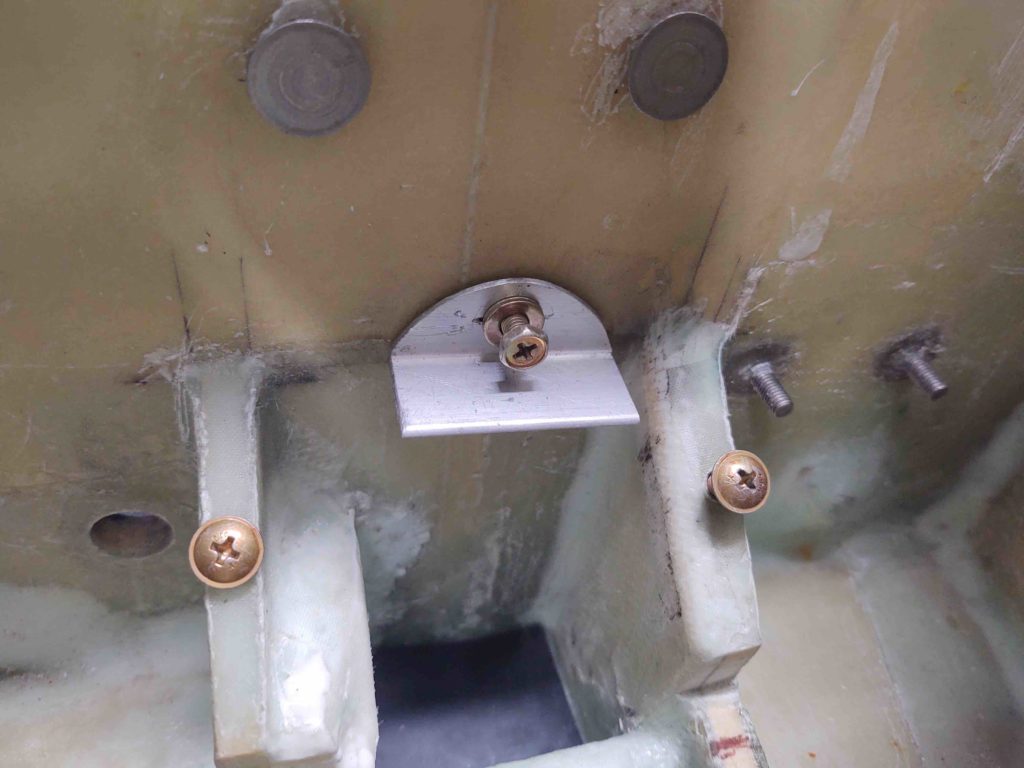
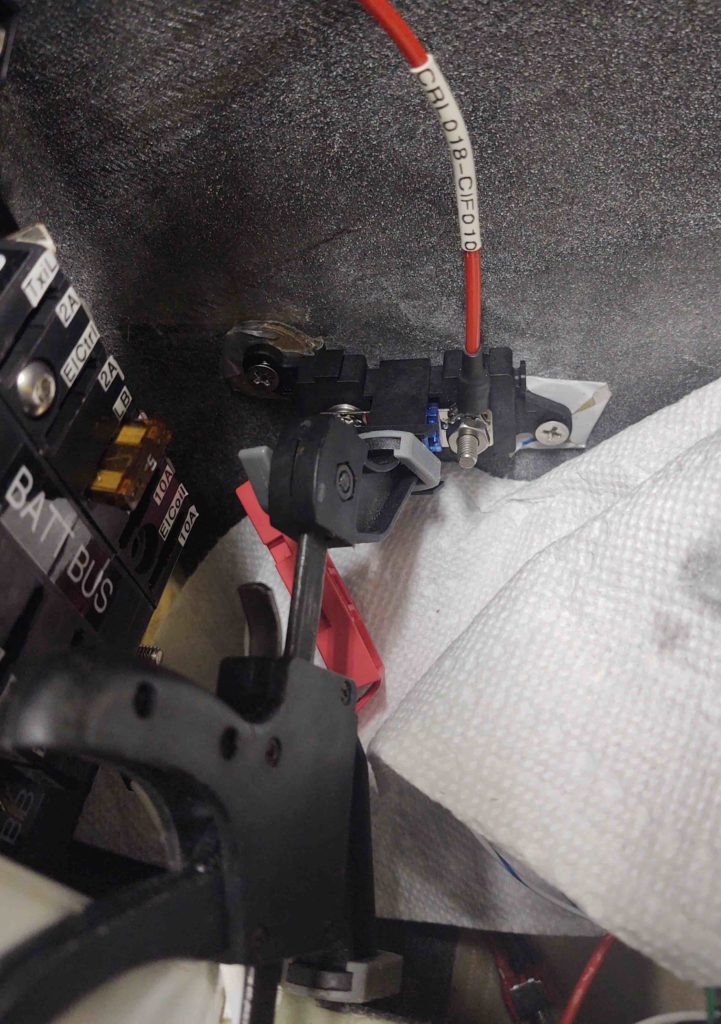
I then figured out where I wanted IF010 placed on the right interior nose, and drilled two holes for the RivNuts that I’ll flox embed into the sidewall.
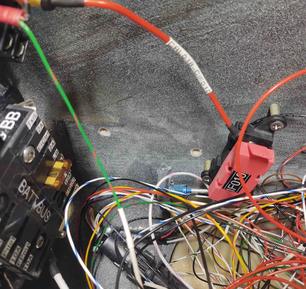
I then floxed the RivNuts that were temporarily attached to IF010 into the holes in the sidewall.
I then got to work on the GIB right armrest storage bin hinged cover.

I first needed to notch the outboard edge of the cover to allow for the hinge assembly. As you can see I used my small bandsaw for this task.
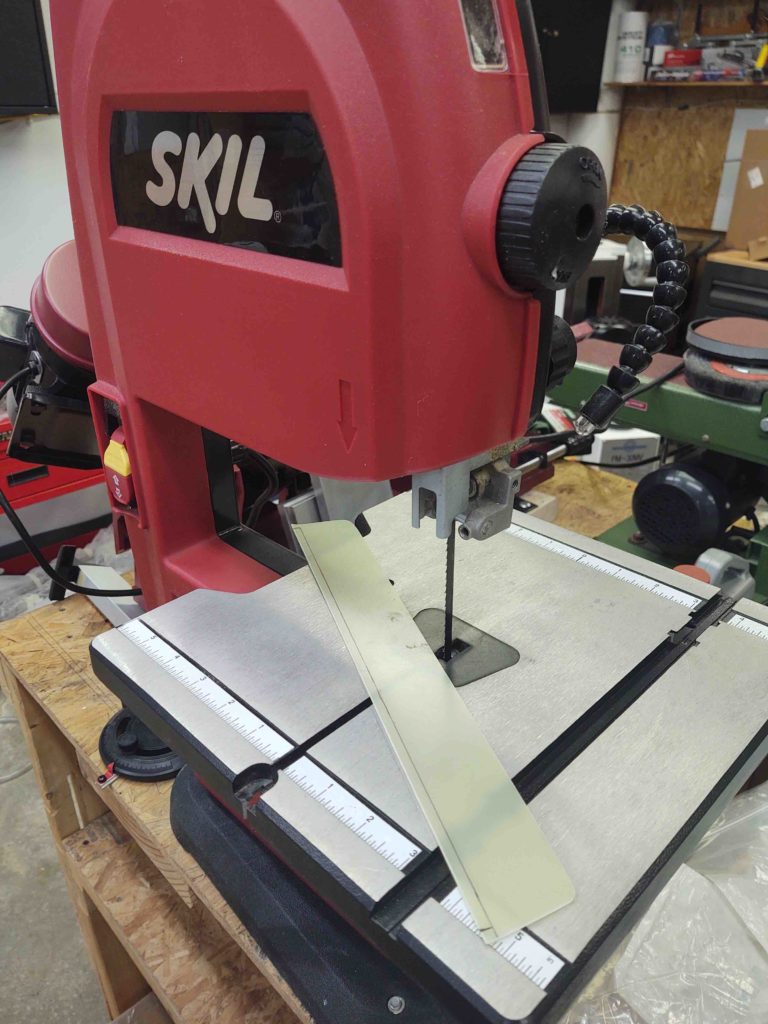
And here’s the result.
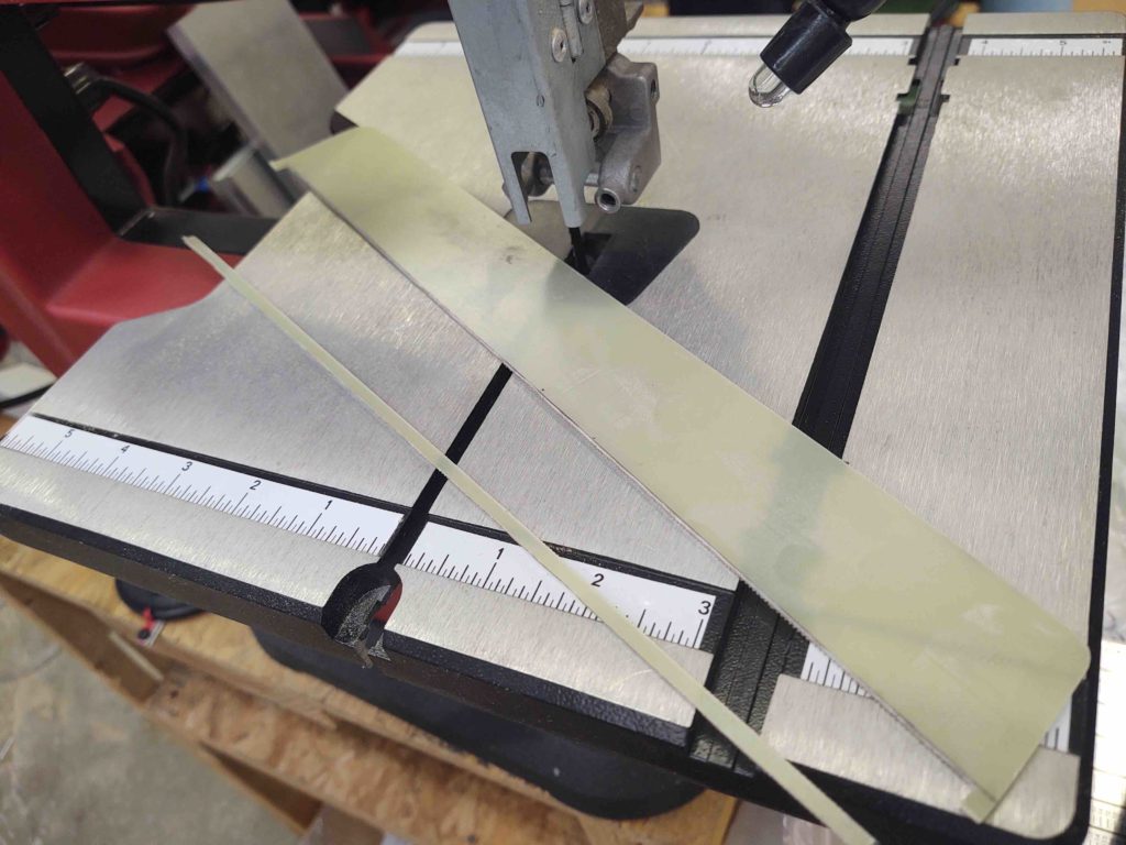
After filing and sanding the above edge straight and smooth, I then drilled some flox holes into the lower hinge half, and then drilled rivet holes in the cover and upper hinge half.
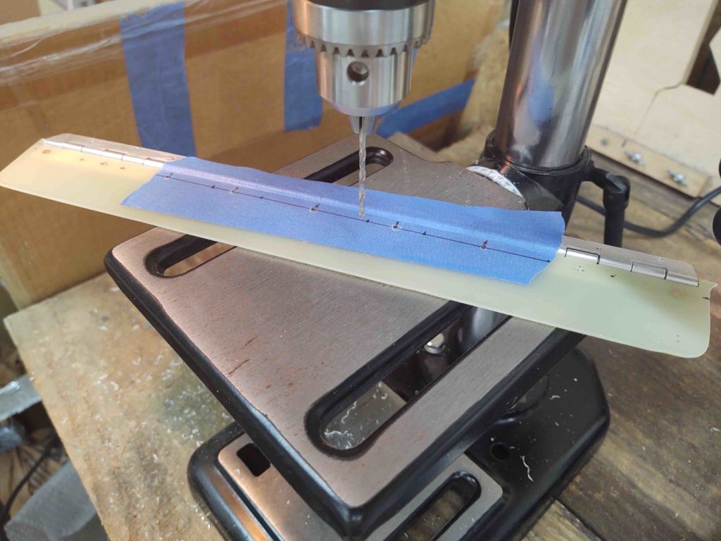
I then riveted the cover to the upper hinge half.
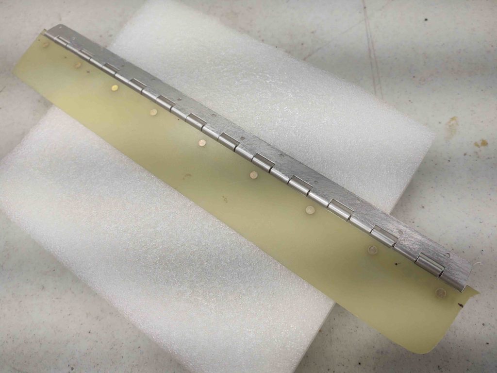
An underside view.
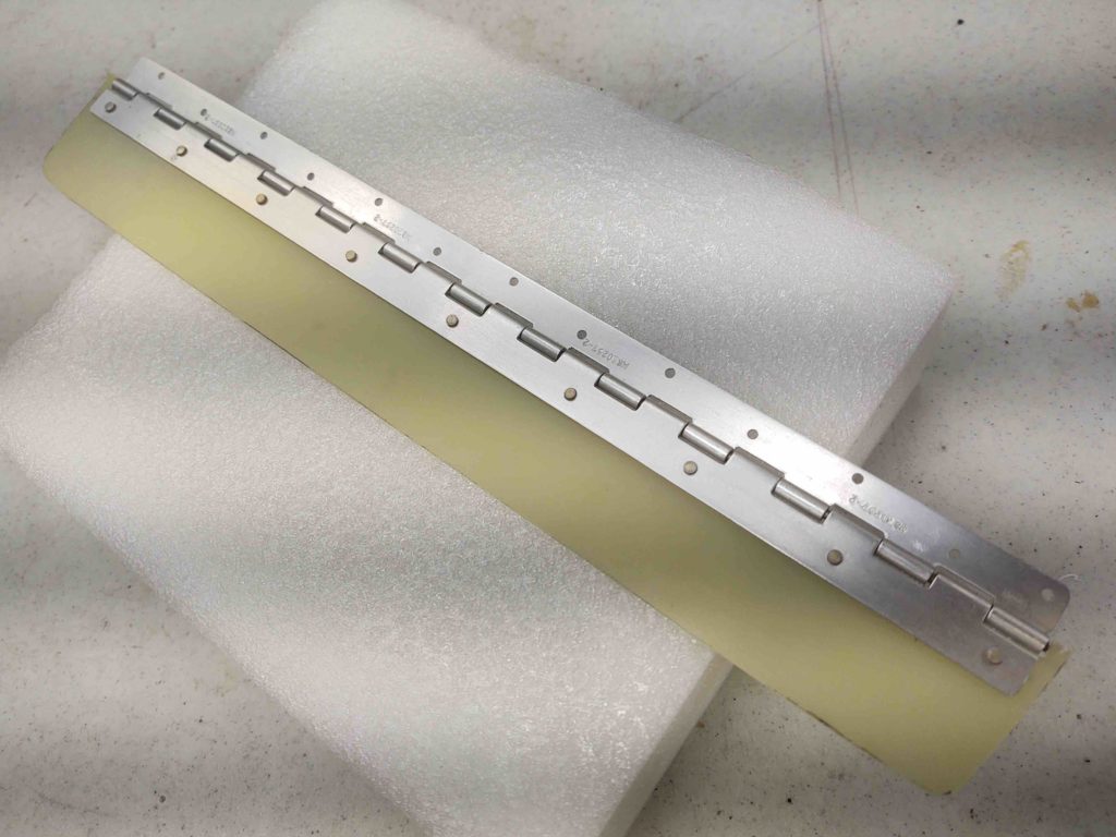
Then using flox and a few dabs of 5-min glue I floxed the lower hinge half onto the right fuselage sidewall.

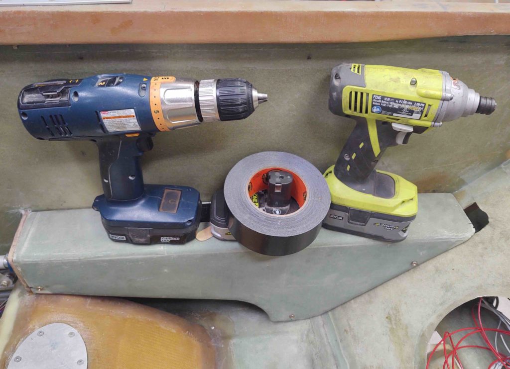
I Gorilla-duct-taped popsicle sticks to the top of the cover overhanging onto the armrest top to create an even plane between the cover and armrest surfaces. I then weighed the edges down with my drills, etc. to ensure it all stayed flat and even.
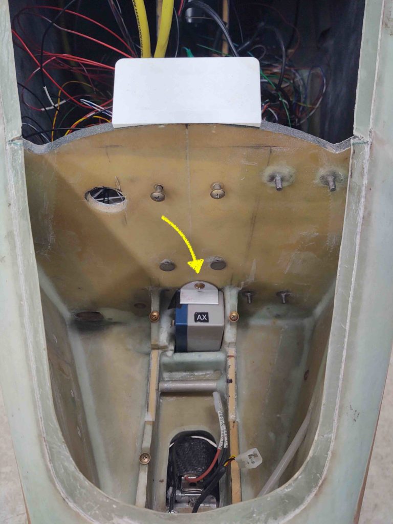
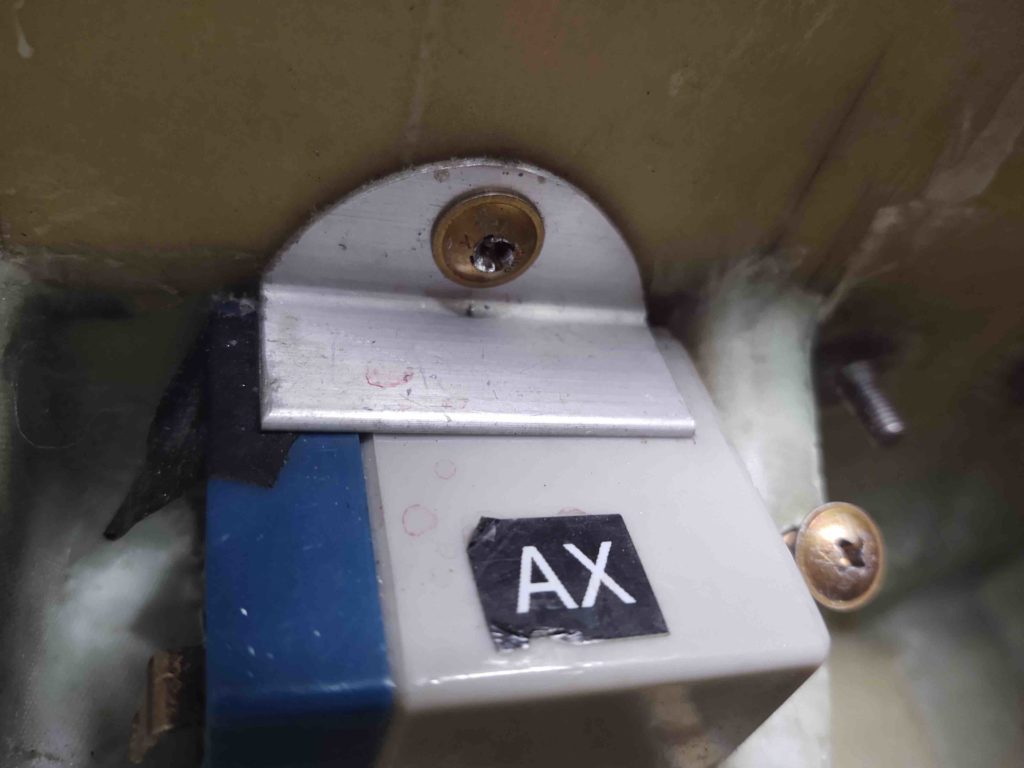
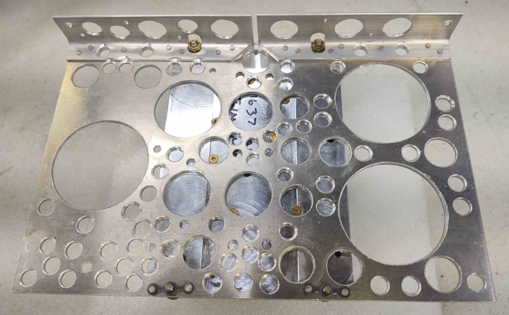
As my flox projects were curing, I then got to work mounting the GRT AHRS to the top shelf of the Triparagon. On the aft side of the shelf I used 2x #6 nutplates.
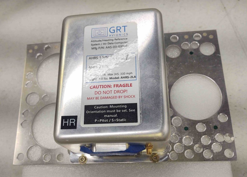
Due to the lip on the front of the shelf, I’m simply using 2x traditional nut & bolts.
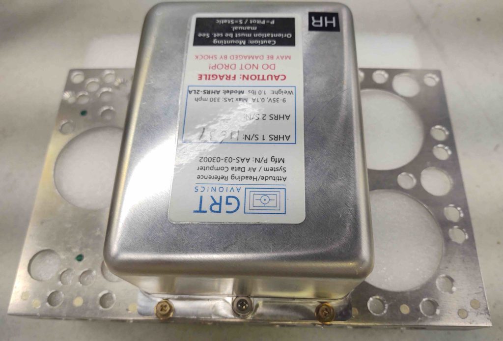
The bottom side shows all this more clearly.
I then got to work installing a Bose headset LEMO jack for the GIB. I thought about this a bit late last year and figured if I was ever going to use a Bose headset for the back seat –which I intend to– then I should install the LEMO jack before I build the strakes… after which working in the back seat area gets infinitely more difficult.
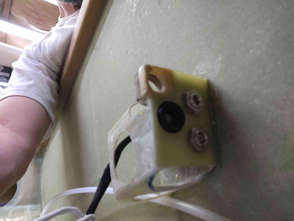
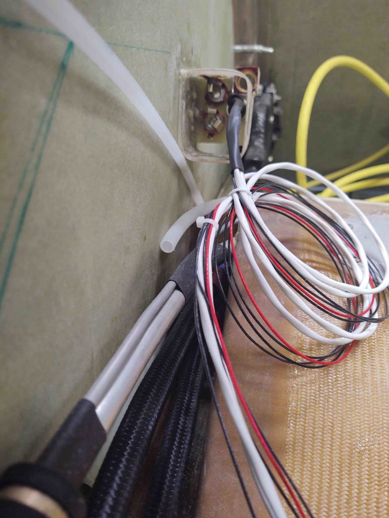
The installation hole isn’t perfect, or overly high craftsmanship, but it works and fits, and looks to be a secure installation. . . so I’m calling it a win. Especially since it just barely fit in there with the existing traditional headphone jacks.
I worked on cleaning up about a third of the inside glass edge of the canopy for about 45 minutes before going back to my initial task of the day: installing the mini-ANL15 base onto the right nose sidewall. Again, just aft of the Napster bulkhead.

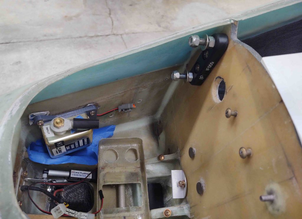
Here are the ANL15 base embedded RivNut hard points after I cleaned them up a bit.
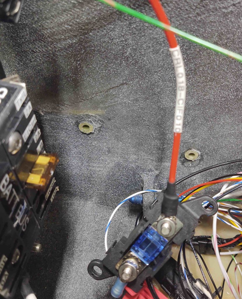
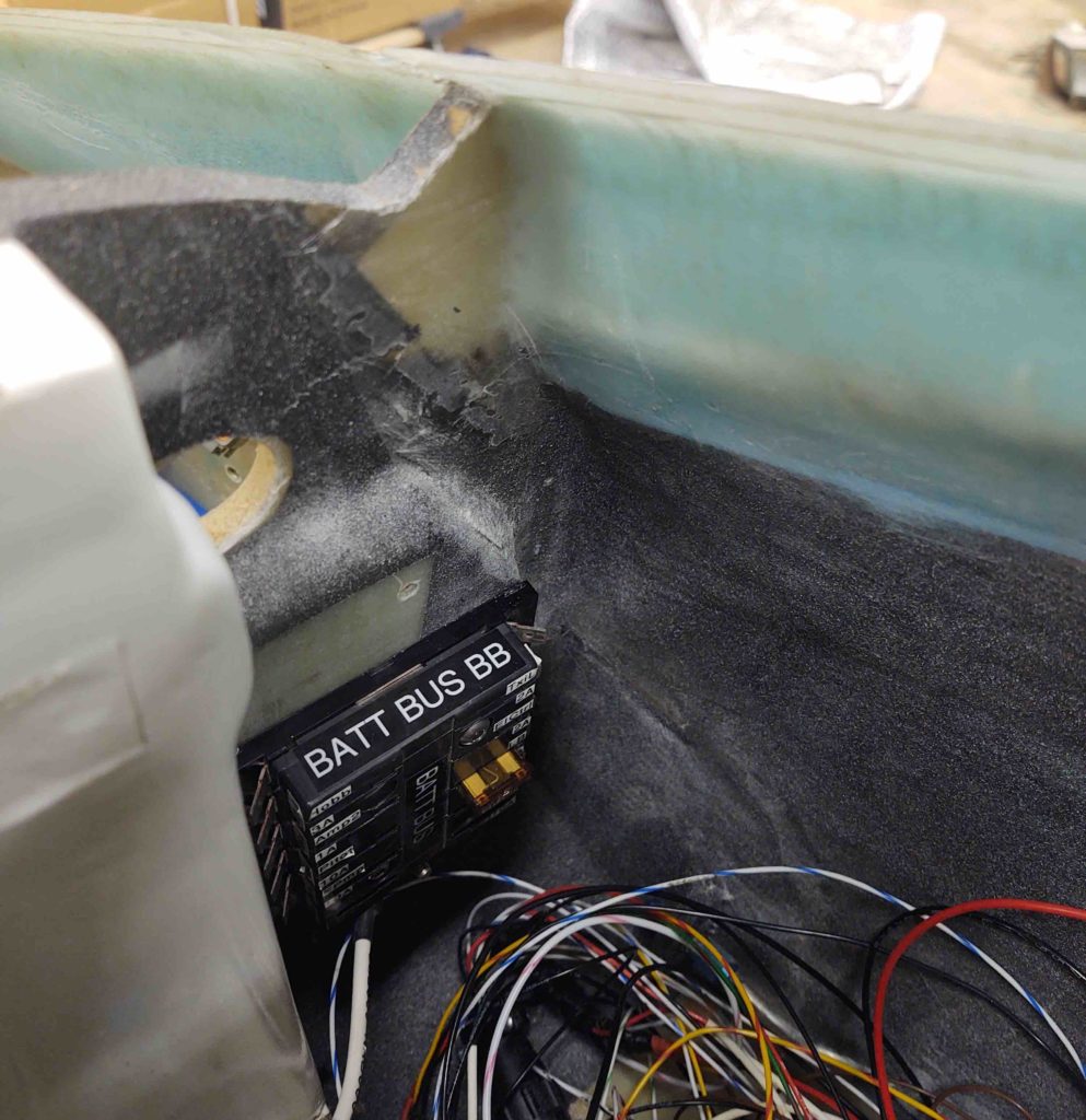
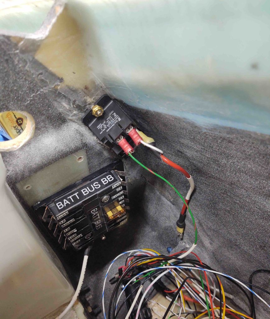
Earlier I made up a cross-connect cable between the Battery Bus post and the other post on the mini-ANL15 current limiter, which I installed at this point.
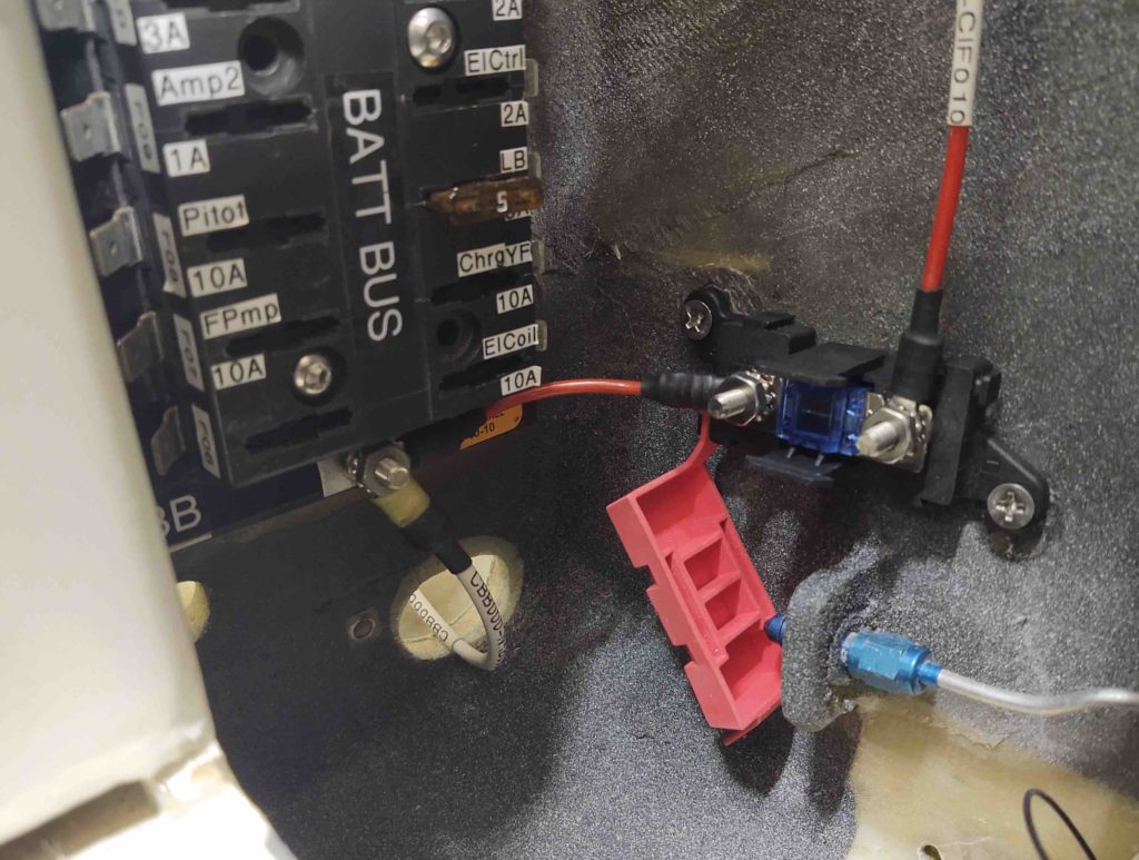
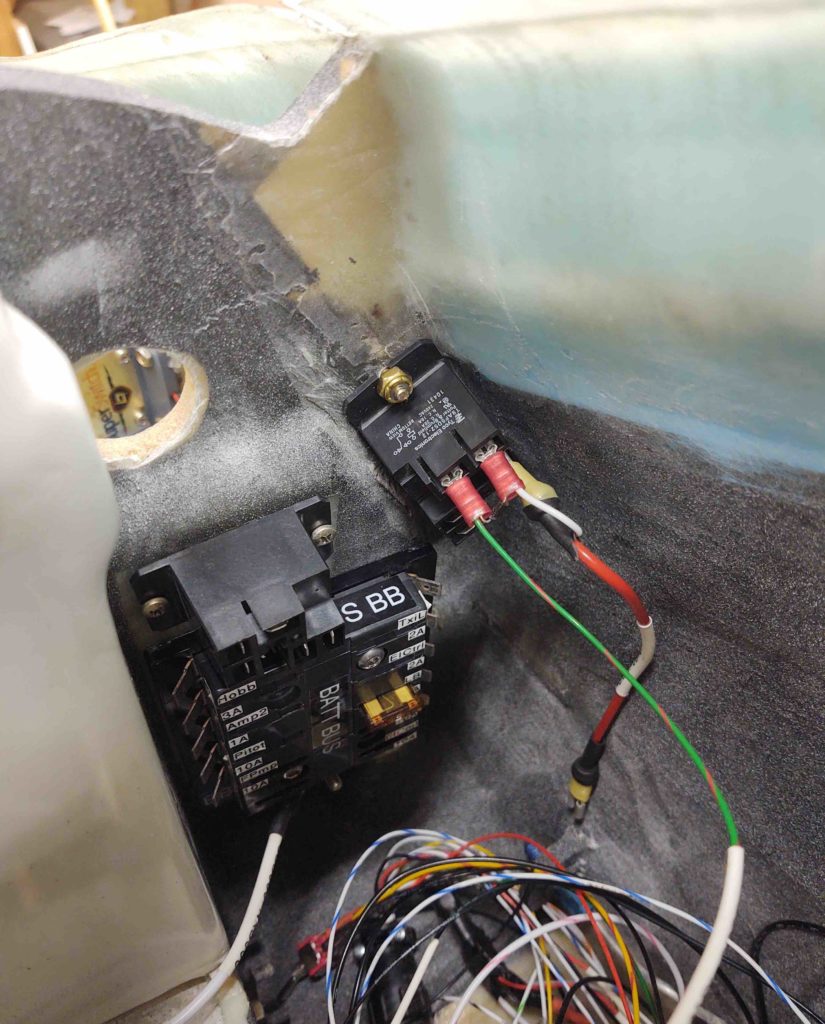
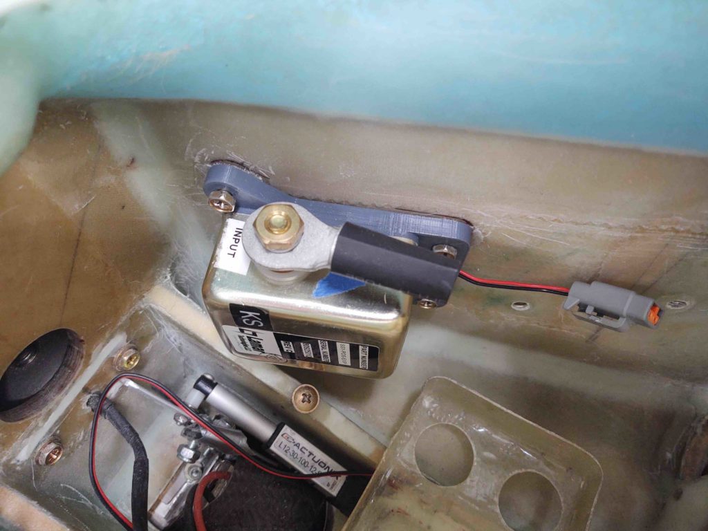
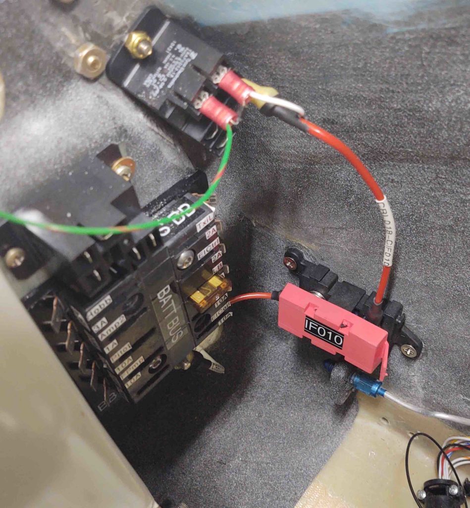
Here we have the finished install of IF010, the mini-ANL15 current limiter.
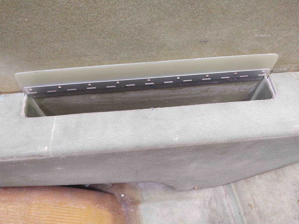
And finally, to cap off the evening I unencumbered the top of the GIB armrest storage bin cover and removed the tape to reveal how it looks. I have to say that I’m super happy with how it turned out.
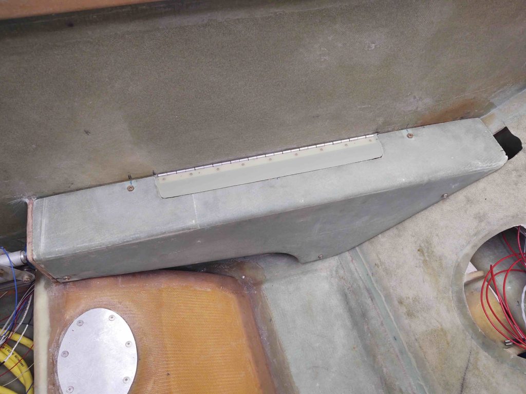
And of course a shot with it open… ready for business!
I suspect I have at least another few days of getting some of this odd ‘n end stuff knocked out before I start sinking my teeth into some bigger build tasks.
Chapter 9 – Look Ma, no Clecos!

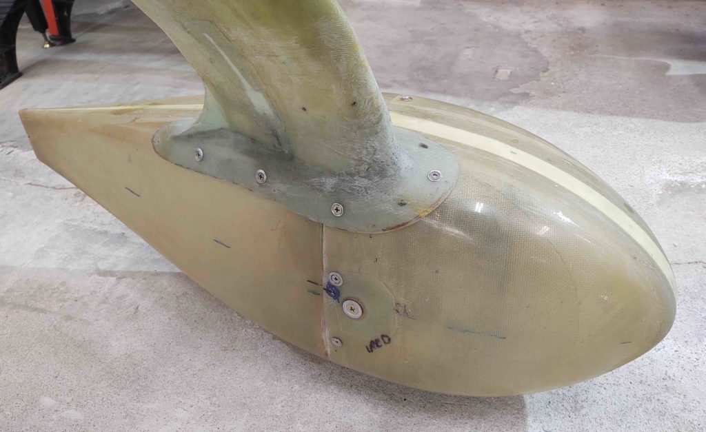
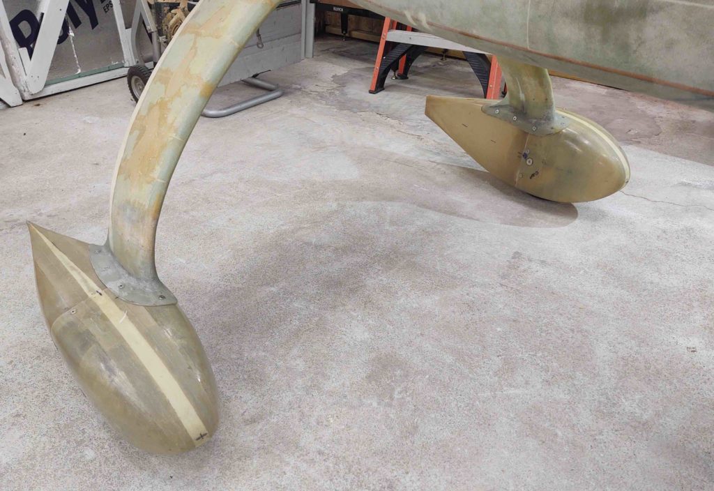
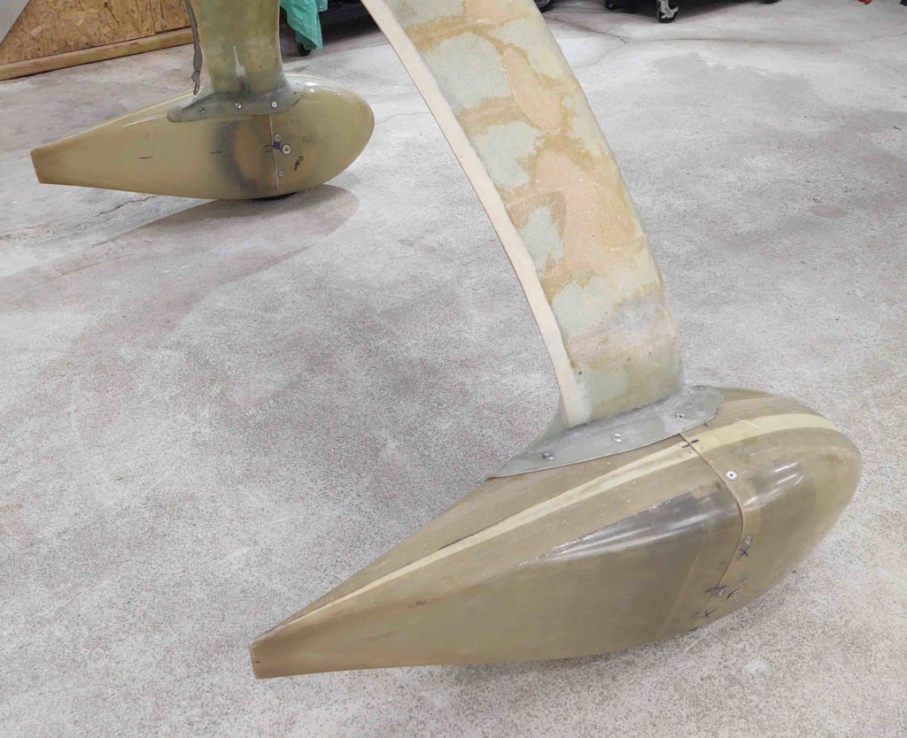
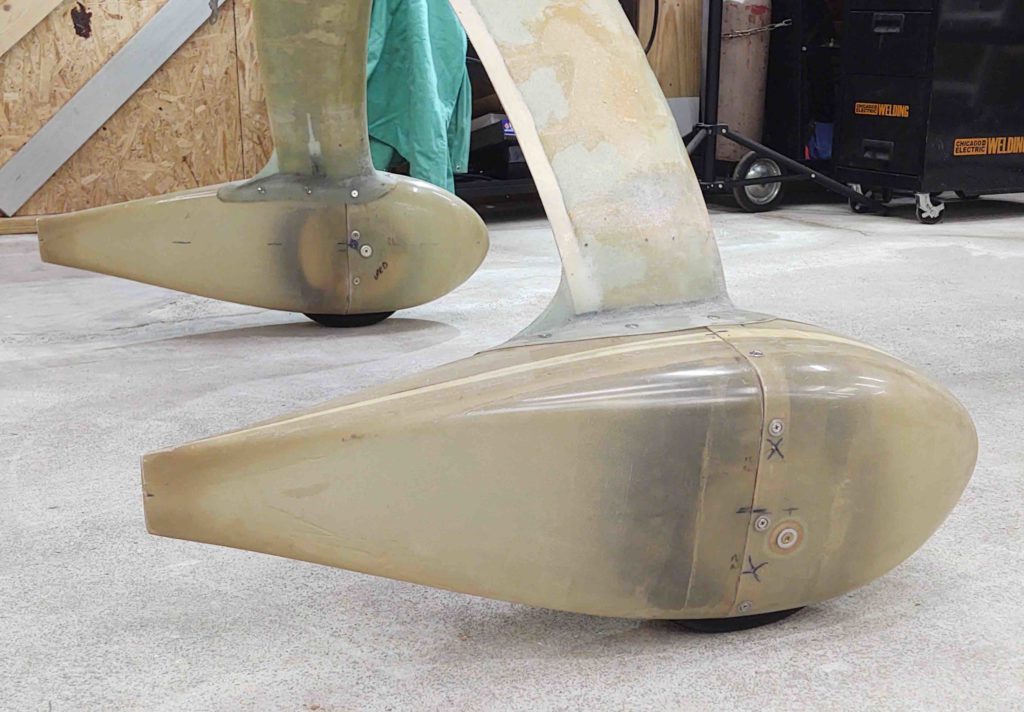
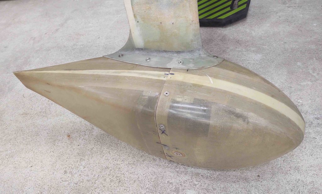
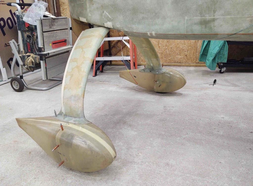
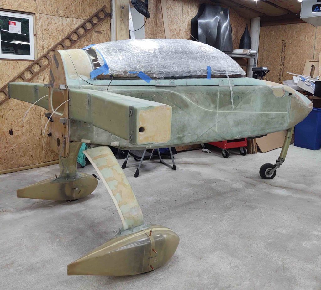
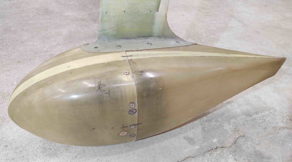
Today I finished the installation of the wheel pants… at least the major heavy lifting as far as the hardware installation is concerned. I still have one more CAMLOC assembly to install (maybe 2 even) and some minor tweaks with pant-to-tire clearance at the bottom wheel openings.
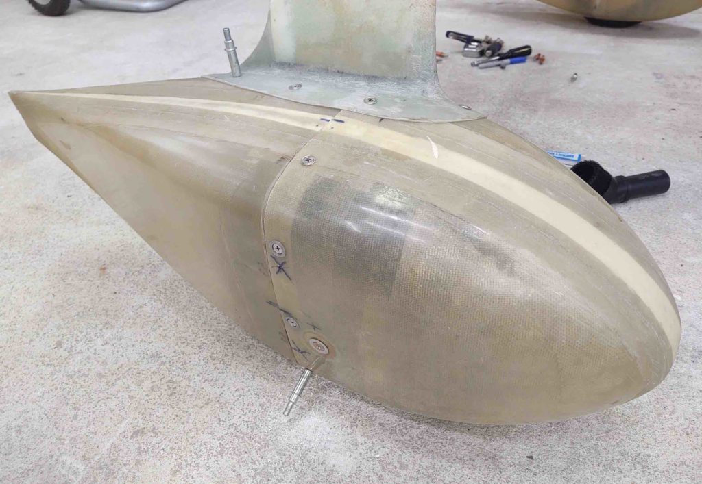
Here is my finishing up the left side wheel pant mid-hardware install.
And a shot of the finished left wheel pant, replete with installed screw and CAMLOC attach points.

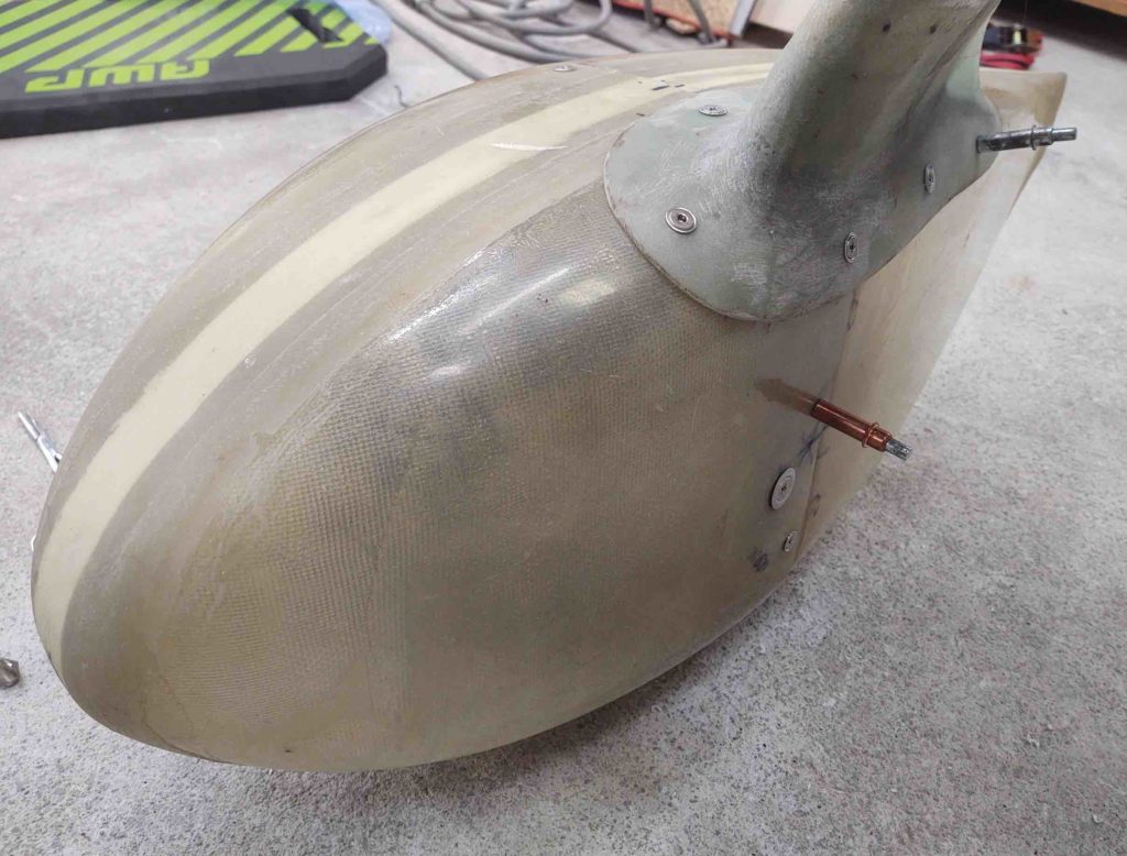
And an inboard look at the left wheel pant.

Can’t let an event like this go to waste, so a couple shots of both wheel pants together.

With this task out of the way, I can obviously focus my time on other parts of the build.

I have to say I’m extremely pleased with how the wheel pants turned out. Of course I think they’ll look even better once they’re finished and painted!

Chapter 9/22 – Right Pant done

But first…. a few things.

As I mentioned before, as I go about the wheel pant install I’m trying to get some components installed… preferably ones that require epoxy/flox to secure them in place. That way as I continue my wheel pant install machinations –which can be a bit slow and tedious– I’ll have something “baking in the oven,” if you will, concurrent to my specific efforts.

Well, today was a setup for that, but I didn’t get to the flox part just yet.

However, I did get a couple of electrical components installed, and as benign as that seems, anything mounted and placed (typically) is another item off the list for mounting, and one less decision that has to be made (admittedly, this is mounting #2 for the ANL40 fuse device… previously mounted in the Hell Hole).

So the goal is to flox in a couple of RivNut hard points to mount this guy here, a mini ANL15 slow blo fuse that protects the Battery Bus-to-E-Bus circuit if the SD-8 backup alternator is feeding the E-Bus directly. Incorporating this was one of the latest significant changes I did to my electrical system and was based on a fairly new system architecture that Bob Nuckolls devised.

BTW, looking up the circuit configuration for this device on my Charging System wiring diagram highlighted that I hadn’t updated the diagram with this new mod…. so I did so before heading to bed.

Back to it.

To figure out where to mount the ANL15 fuse above, I would need to understand my spacing requirements. I plan on mounting it on the right nose sidewall just aft of the Battery Bus.

So I rounded up the Battery Bus and temp installed it.

Since I am once again using a S704-1 relay to control the SD-8 straight power feed to the E-Bus (I had removed it on the advice of Bob Nuckolls when he reviewed my electrical system architecture), since it is now back in play with this new E-Bus feed schema.

So I needed to mount this relay for two distinct purposes:

A) Since this relay controls the E-Bus power feed (AKA on/off switch) it connects directly to the ANL15 fuse. Thus I need to know the relay’s required distance from the ANL15 as determined by the length of the pre-existing power wire (big red wire) that will run between the two devices.

B) Since I’ll be mounting the ANL40 fuse base on the front side of the Napster bulkhead close to opposite the position of this relay, this relay getting mounted is a prerequisite task to then mounting the ANL40 base… since screw clearances through the bulkhead can be maintained.

As you can see below, I then proceeded to drill & countersink (front side of bulkhead) the required holes and then mount the S704-1 relay.

Since I had the Heated Pitot Tube S704-1 relay on hand I went ahead and temp mounted it in place above the Battery Bus.

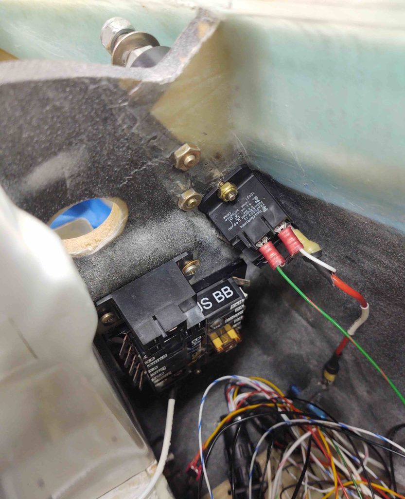
With the E-Bus feed relay mounted in place, I then mounted the ANL40 fuse base on the front side of the Napster bulkhead while ensuring its mounting screws missed the components on the back side of the bulkhead.

As you can see here with the two ANL40 fuse base screws poking through the backside of the Napster bulkhead.

With this all done, I will cut off the red wire’s Fast-On connector, re-lable the wire and then terminate with a ring connector. I’ll actually fasten the ring connector to the ANL15 fuse block and leave it connected as I mount the ANL15 on the side wall.

Yes, all this fuss for pretty much simply drilling 2 holes and flox-embedding a couple of RivNuts into the sidewall for a fuse block!

Ok, now for the fun stuff!

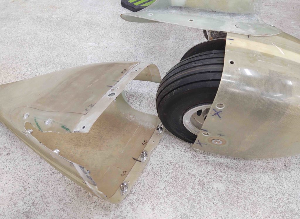
I finished mounting the CAMLOC hardware on the right wheel pant. It really is a time-consuming process, but I’m really happy with the results.

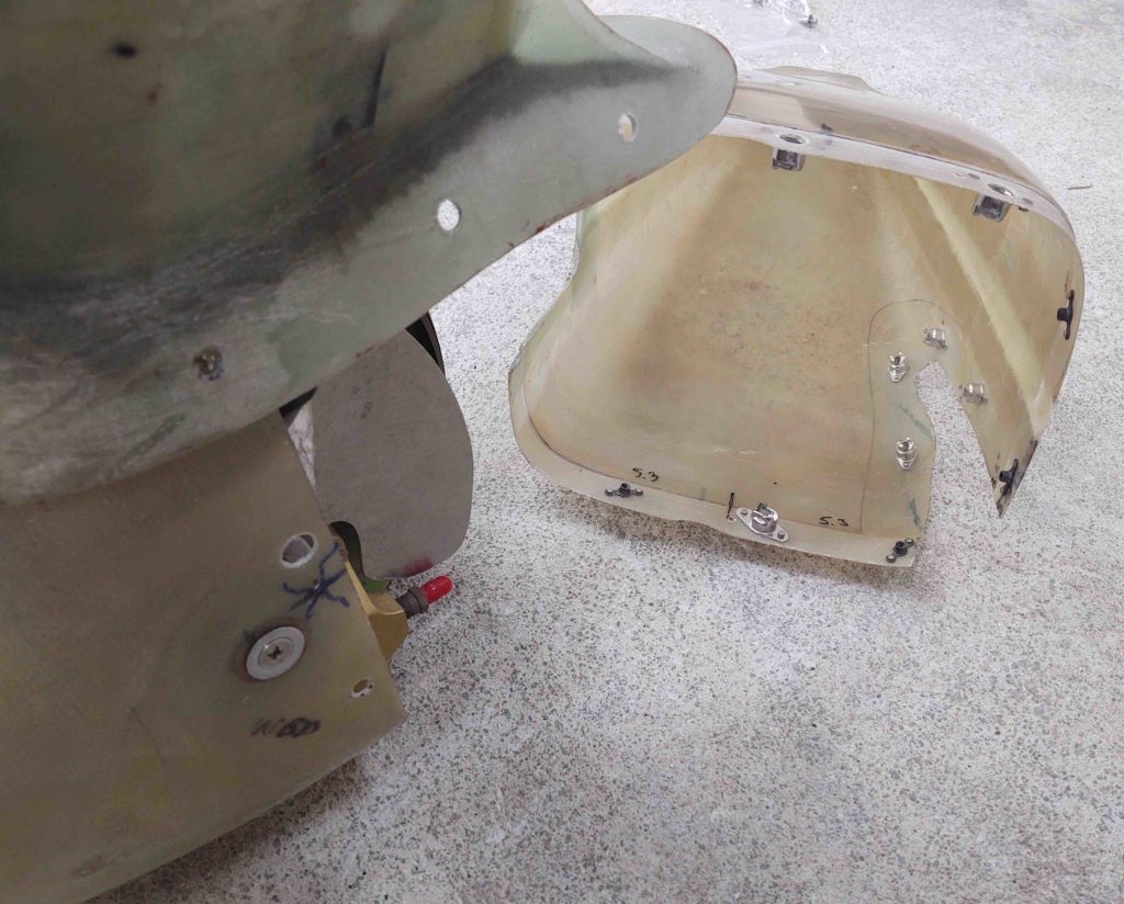
Here’s a shot showing some of the interior hardware on the back half of the wheel pant, and the through holes in the front of the pant.

And same here on the inboard side.

Here’s the right wheel pant in all its mounted and finished glory!

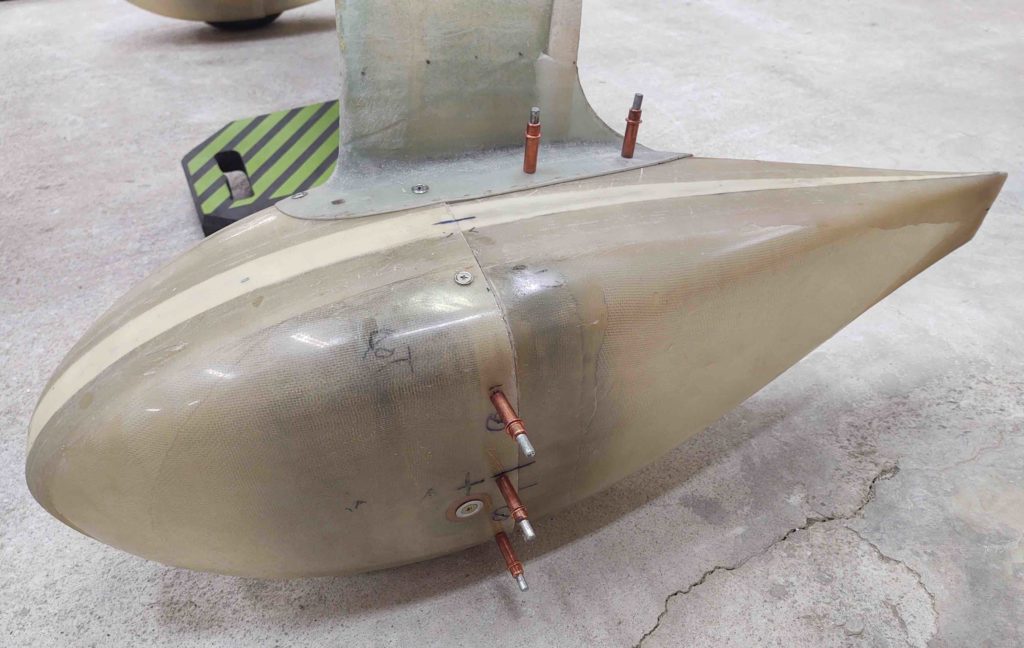
A closer-up shot of the hardware. Again, all told to take off the aft pant section to gain access to the wheel requires removing 4 screws and 8 CAMLOCs.

The outboard side of the right wheel pant showing 3 CAMLOCs.

And a closer-up shot of the inboard side, with 2 screws (top/apron & bottom centerline) and 3 CAMLOCs (one midpoint centerline, and 2 on the aft apron).

Entire inboard pant view.

I then relocated and re-drilled the screw/CAMLOC attach points on the left wheel pant, following the same pattern I implemented on the right wheel pant. Again, this adds one more securing point on each side of the pant.

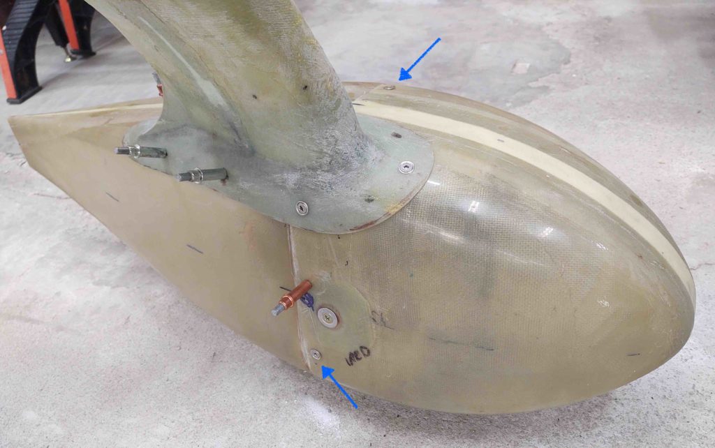
To close out the evening, I drilled and riveted 2 nutplates in place to add the last screws that will be installed on these wheel pants {blue arrows}. The remaining installs will all be CAMLOCs from here on out.

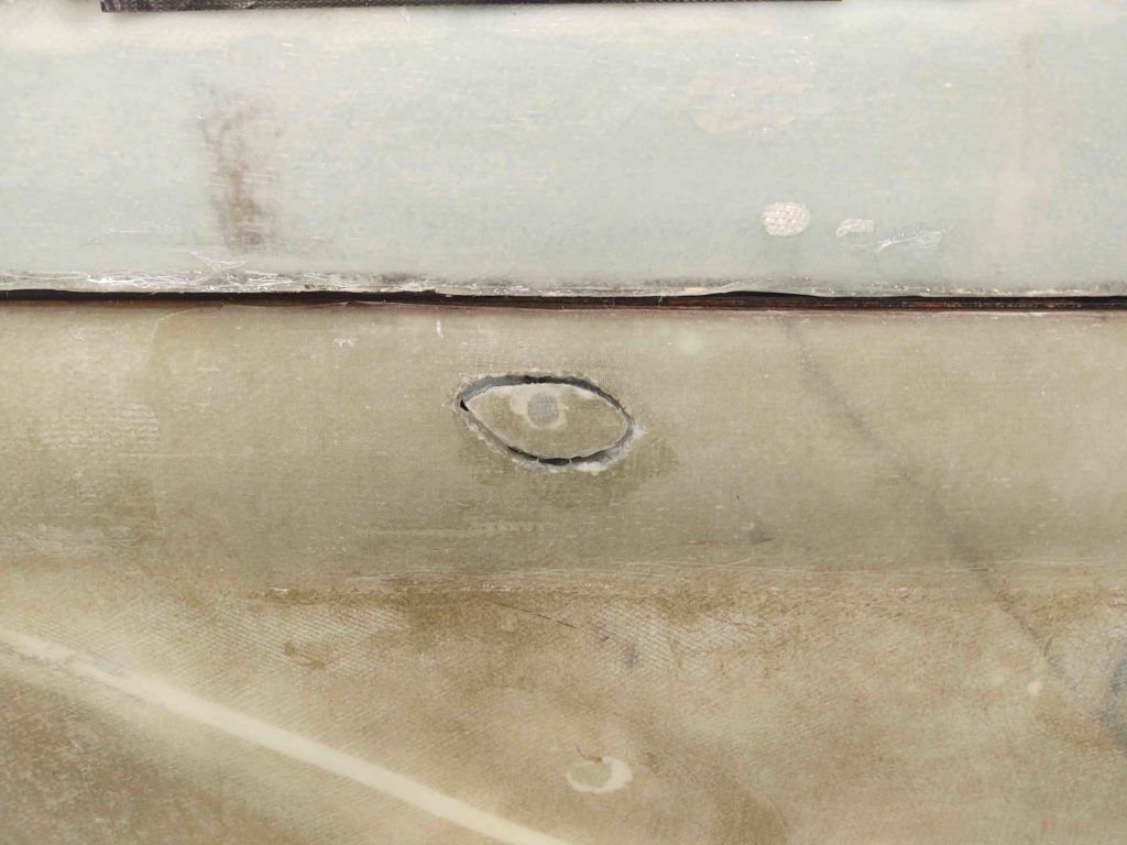
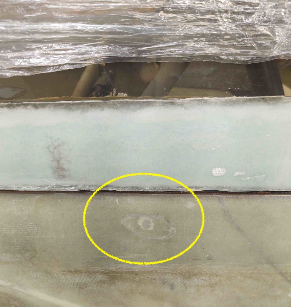
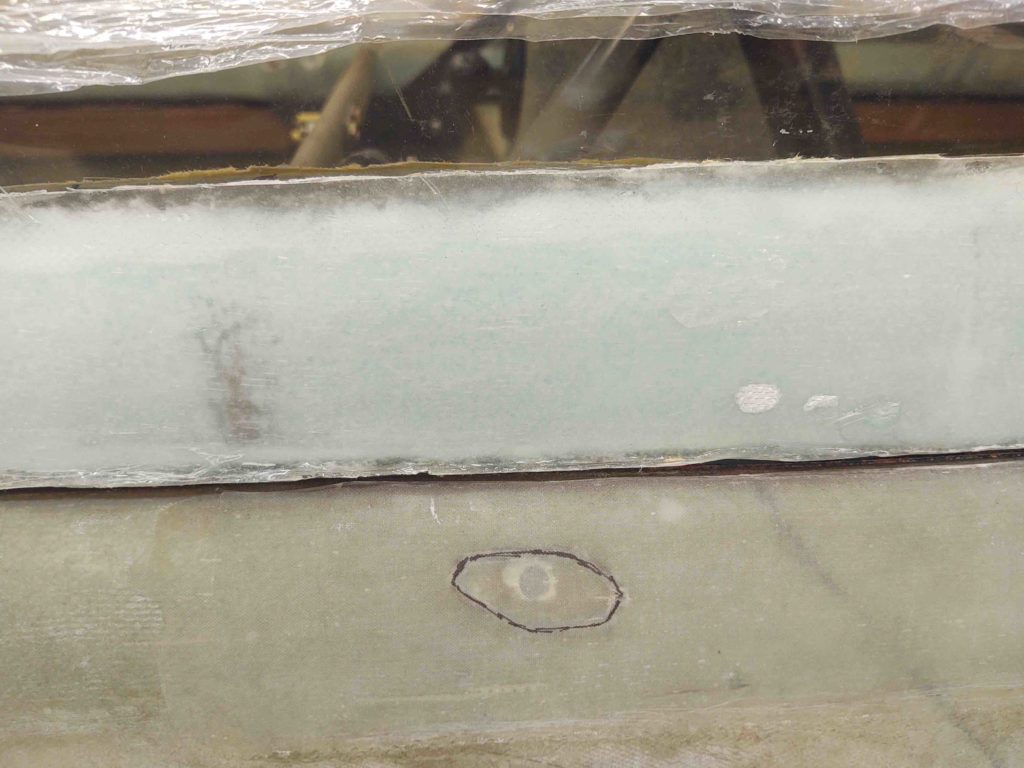
Since I was remiss in not showing the removal of the access plug I made to assess the rollbar bolt securing nutplate, here’s a shot of it after I floxed it back into place. I’ll fill the gap in with micro and glass over it with BID tapes when I build the strakes.

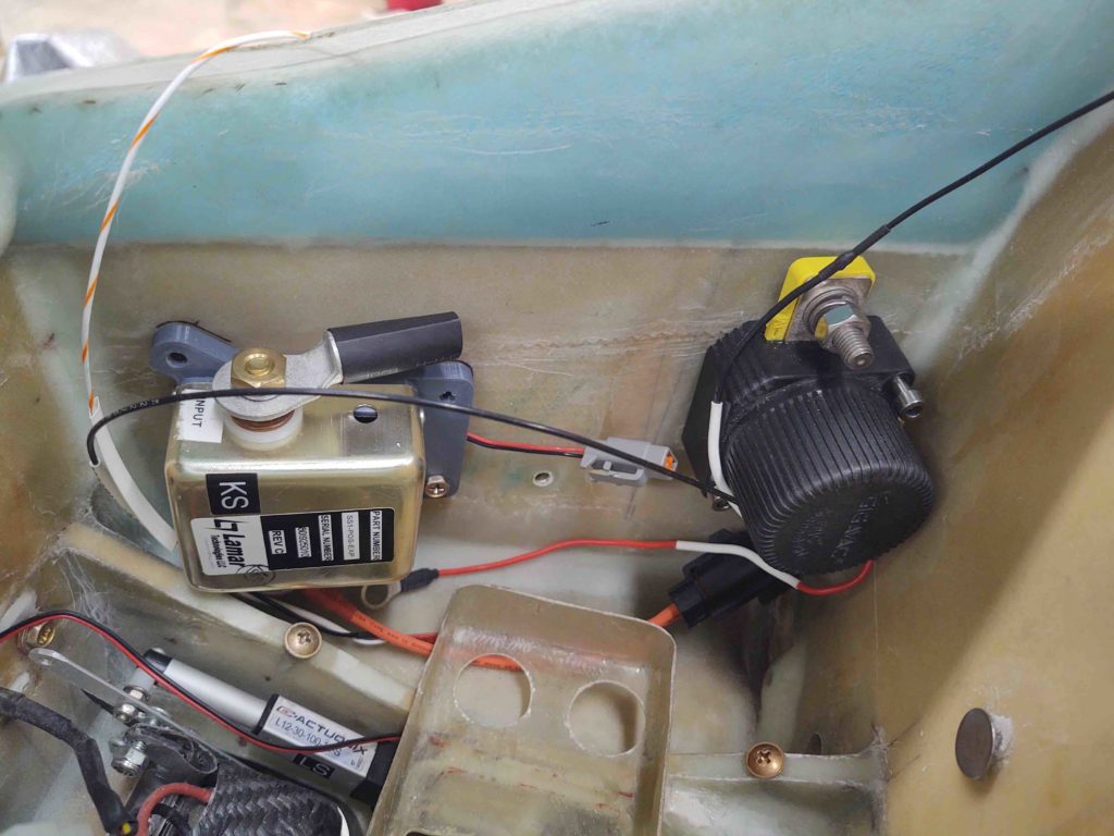
Here we have the Starter Contactor installed. The embedded RivNut bolt hard points came out nicely and I can check this component off the list as positioned and installed.

I will continue my madness of wheel pant install intermingled with other odd tasks for the upcoming week. I plan on working essentially the centerline of the plane, and specifically the GIB area before I build the strakes (note, first will come winglet installs).

As a point of note, I finished off my time in the shop this evening with another 45 mins of cleaning duct tape residue off the very inboard area of the right CS spar and fuselage. I’m thinking 1-2 more cleaning sessions and I’ll have all the tape residue, etc. removed from the bird.

Chapter 9 – Wheel Pant Slog

A couple of things before we get to the wheel pants, since I’m going chronologically here.

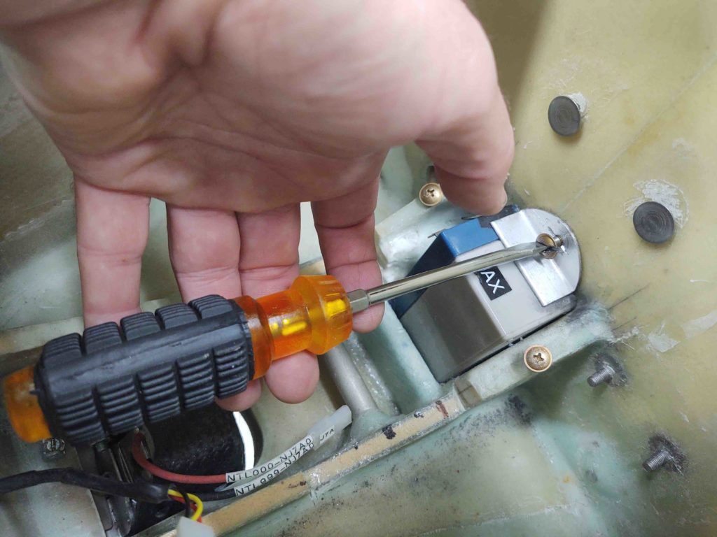
Realizing I wasn’t getting that darn button head screw out in normal fashion, I had to resort to using the Dremel Tool to turn the phillips head screw into a slotted one.

With even more PB Blaster, it was still quite a pain to finally get it to budge. But then it finally gave up and came out.

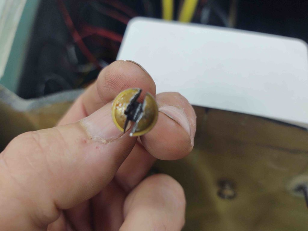
Here’s the destruction of the screw….

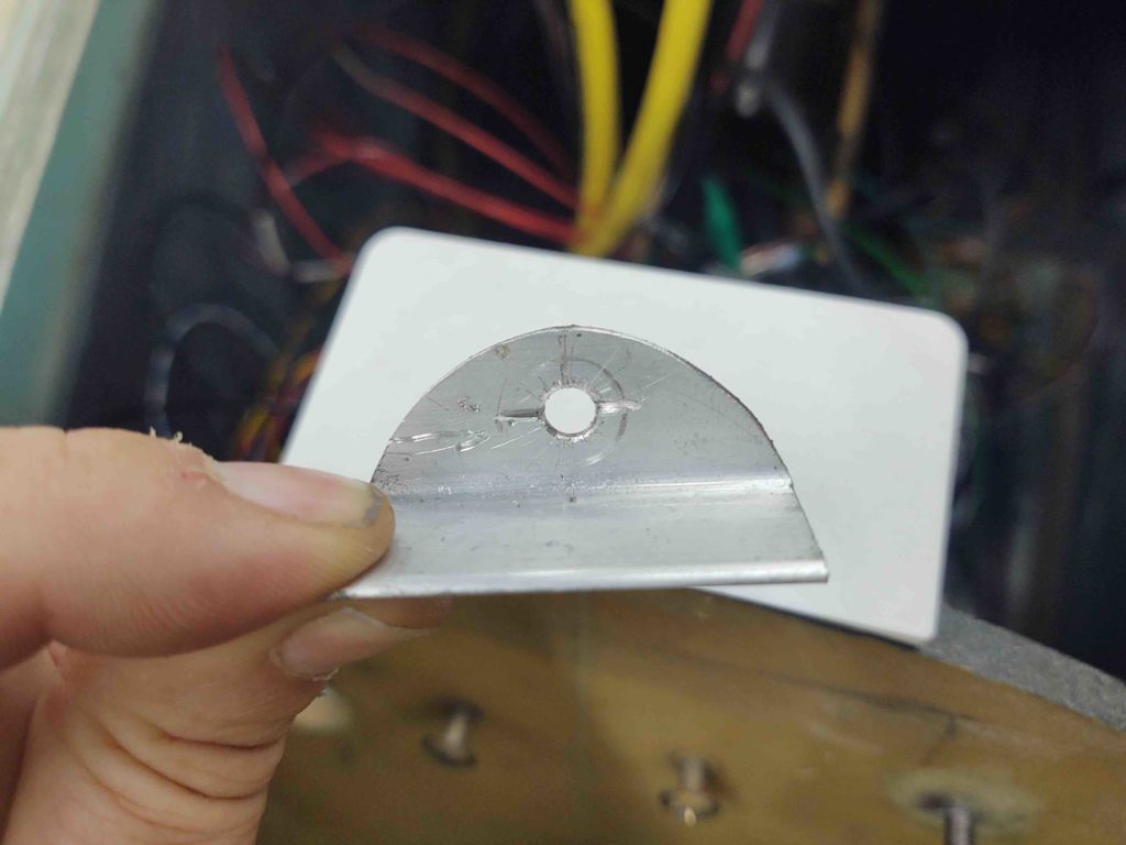
I even nicked the battery retaining bracket a bit . . .

Yep, lesson learned. Although there are a couple button head screws in this pic, they will be from here on out greatly minimized in my plane!

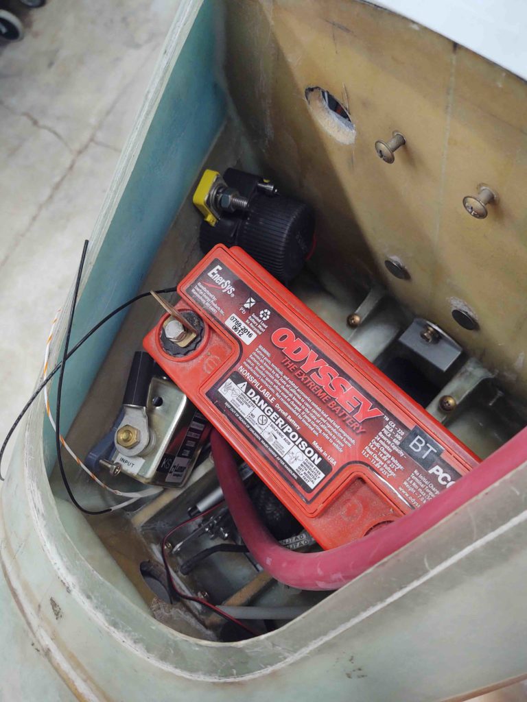
With the nose gear backup battery getting charged, I then set my sights on the battery compartment. I assembled the starter contactor (attached to its 3D-printed mount), the battery contactor, and the battery. I mounted them in place (repurposing one cable clamp hardpoint for the starter contactor) and then assessed cable runs and configurations to ensure all would fit.

After figuring out the big cable runs, I then zeroed in the final position of the starter contactor (I also dialed in the position of the ANL40 alternator fuse bracket — not shown).

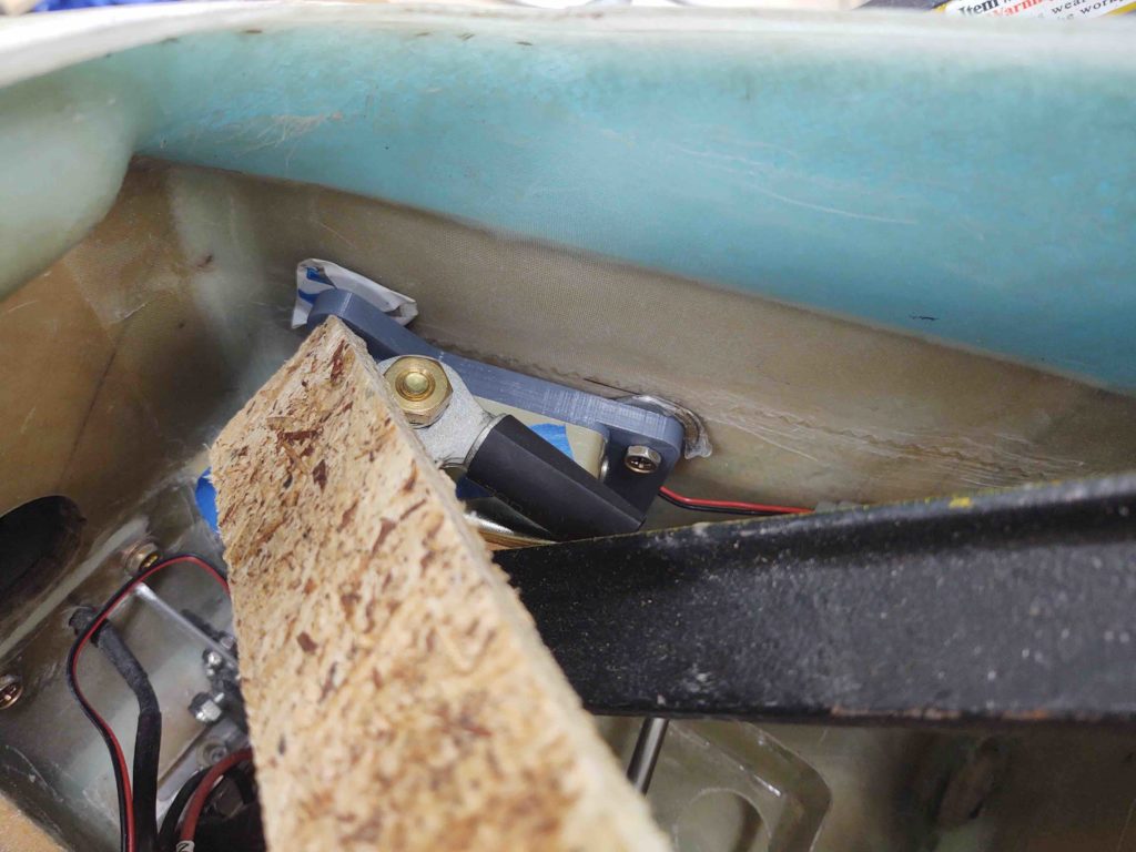
I drilled holes for the starter contactor mount bolts, prepped some RivNuts and floxed them into place on the front right sidewall of the battery compartment. The wood strip wedged into place and black steel part of a clamp are holding it all tightly into place as it cures.

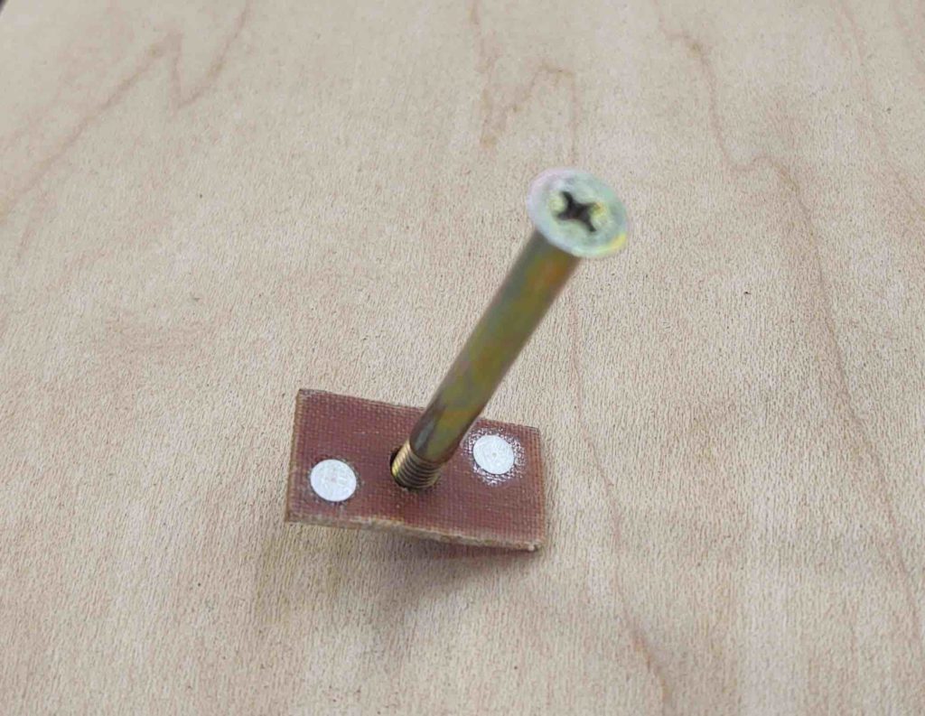
Using flox from the same batch, I then floxed in the phenolic nutplate assembly onto the bottom of the longeron for the aft RHS rollbar frame reinforcement screw.

I used a thin washer under the screw head to ensure I could get the screw out after the flox cures, although I did apply a thin coat of grease to the end of the screw threads.

Finally having some flox components curing, I got back to working on the right wheel pant. I’ve been slowing averaging a couple of hardware (screws or CAMLOCs) installs per day over the past few days.

My method has been to install the hardware points in pairs, with one high on one side and one low on the opposite side, then switch the next time around. Shooting for around 180º as if tightening bolts in a radial pattern.

Here you can see I only have 2 positions remaining to complete on the outboard side.

And 2 positions remaining on the inboard side.

I know I’ll be short hardware for the left wheel pant, but I want to go as far as I can before placing an order with ACS simply to ensure I account for all the hardware I’ll need for both the wheel pants and possibly other components.

Chapter 8/18 – Rollbar vs Canopy

As I physically install hardware on the wheel pants (will discuss in following post) my goal is to get some tasks requiring floxed parts completed so they’ll be curing as I go about my wheel pant install business.

Well, getting back into the plane building game after the big move is proving somewhat challenging just in finding tools, components, hardware, build notes, install instructions, etc. Believe you me there’s a lot more searching for stuff going on than building at this point. But of course as I find and organize stuff I’m slowly getting back into the groove of things.

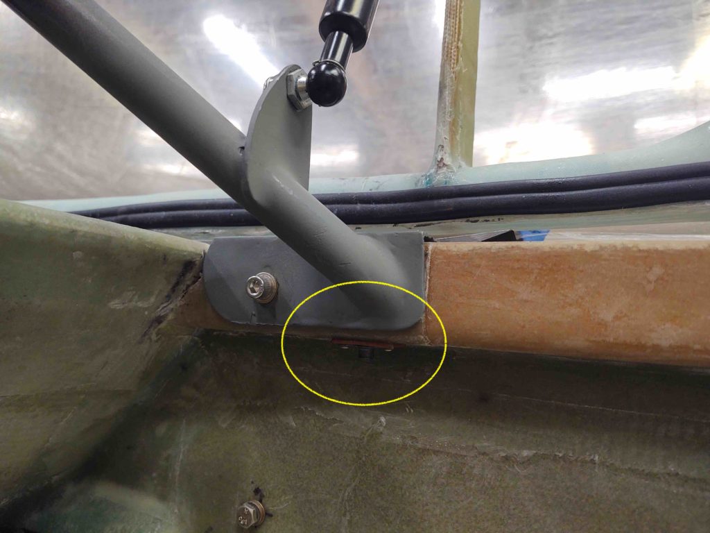
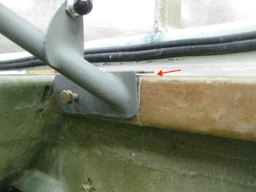
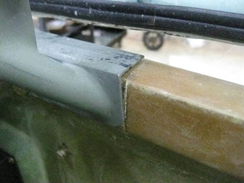
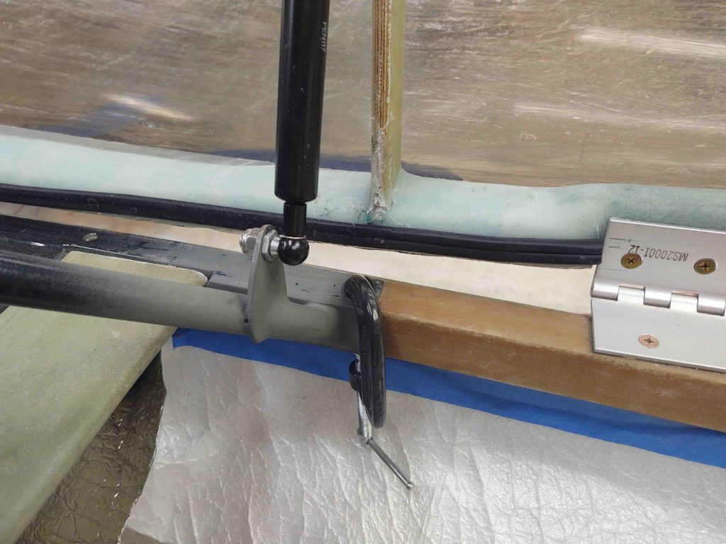
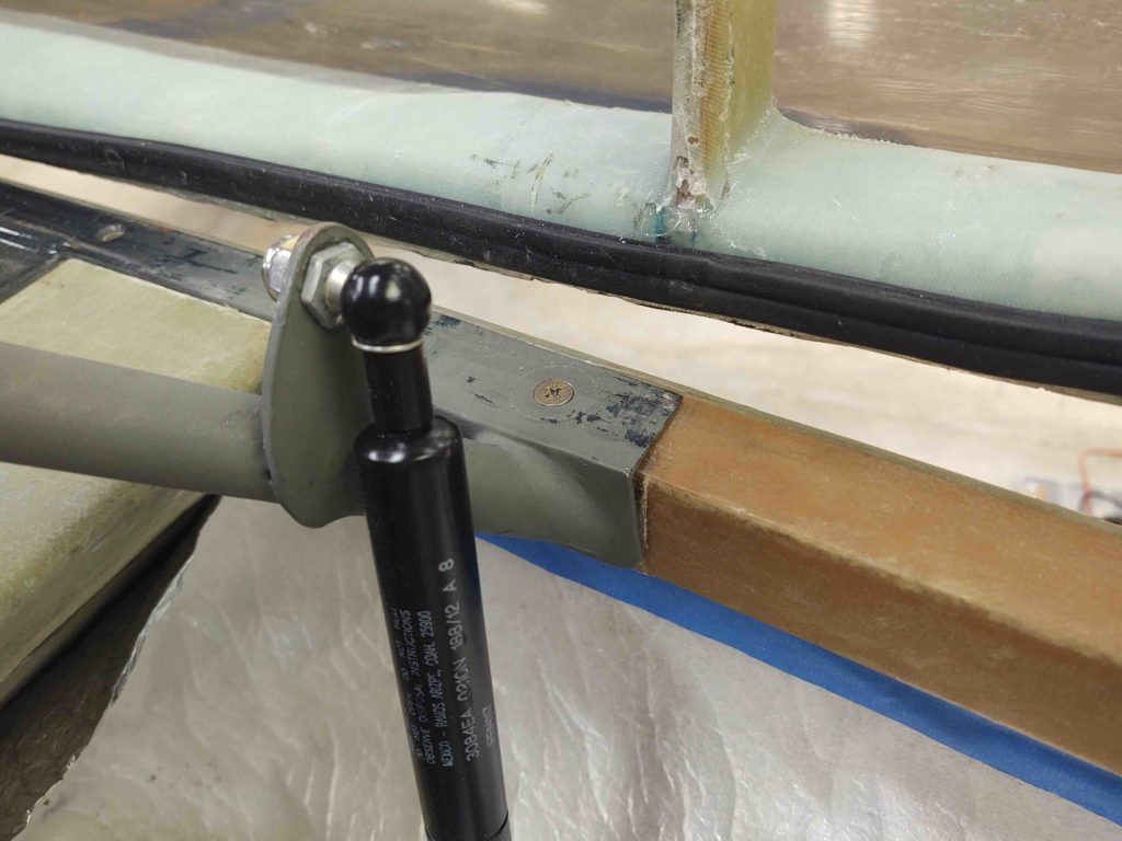
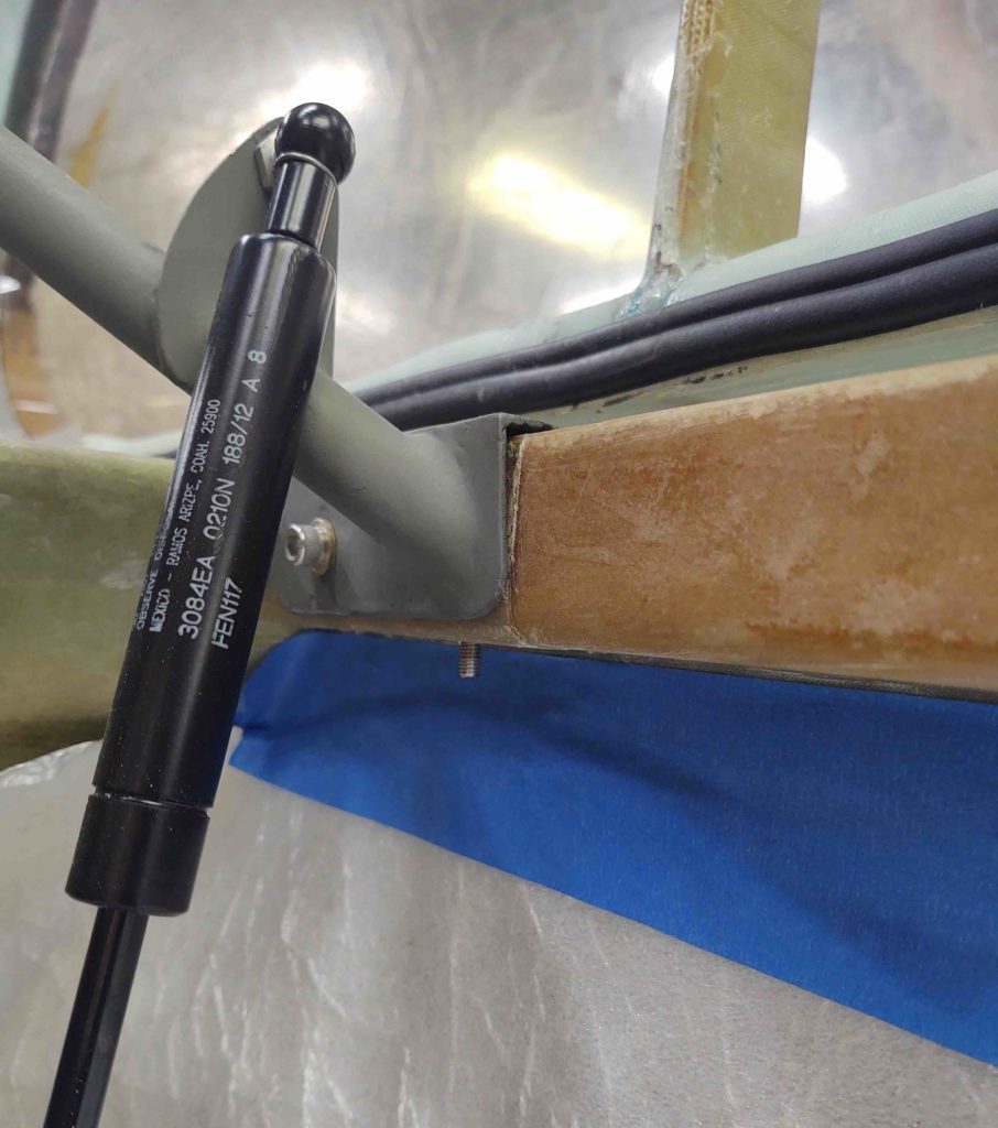
One such flox task is the minor issue I’ve noted with the canopy gas spring attach point. Not an issue with the gas spring or geometry or operation itself, but the fact that the hefty mo-jamma canopy is pulling the back end of the rollbar rail up slightly when the canopy is open. Note the visible gap I have the red arrow pointing to in the pic below.

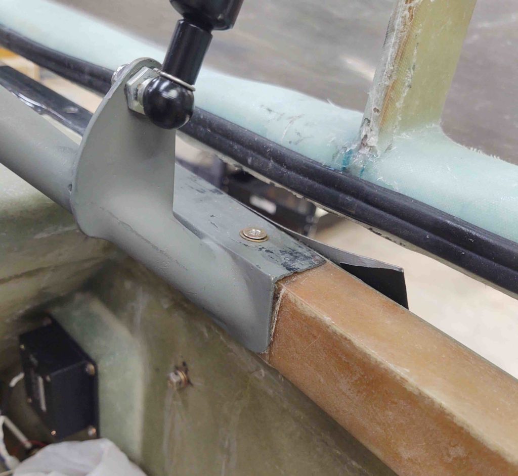
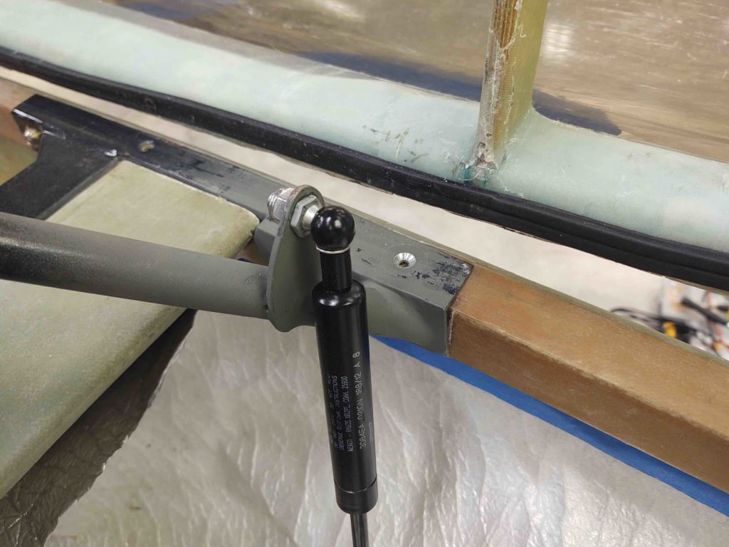
Here’s a view of the top of the rollbar attach rail, aft end,

Now, Murphy always seems to extract his commission on what appears to be a simple screw installation on the rollbar rail…. But here’s where protracted builds start showing their ugly side.

My thinking was that before I drill a hole DOWN through the longeron I wanted to ensure the roll bar rail was installed SNUGGLY to the longeron with all the bolts in place. I had on hand some fancy stainless steel hex-drive cap screws for the final install of the rollbar. I even had 4 of them (2 front, 2 aft) in a baggy marked for that purpose.

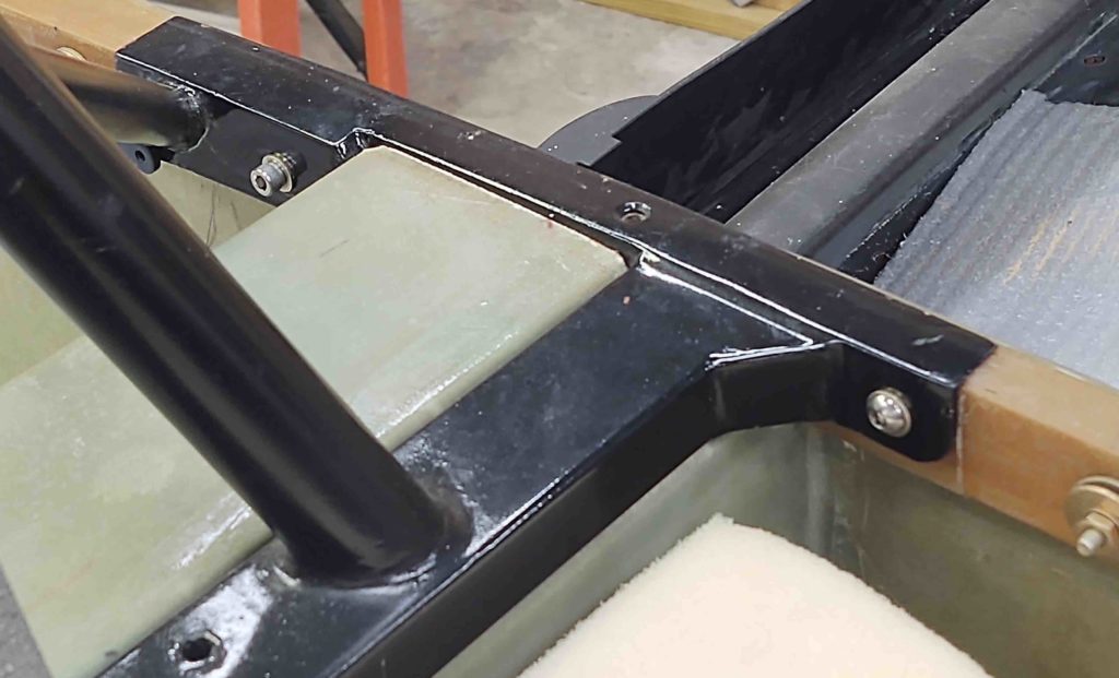
I’m going to jump ahead here pic wise to show the bolt configuration of my rollbar: one 1/4″ bolt on the front side of each rail, one 1/4″ bolt on the back side of each rail, and one 3/16″ CS screw in the middle area going vertically down into the longeron.
Note different style bolts… key to the story later on.

Well, as I kept trying to completely thread in the existing bolt (I had in “finger” tight) and then one of the pre-identified cap head screws into the aft rear bolt hole, I was getting it to thread in, but then at the point to tighten it appeared to be stripped. The bolt would just spin.

I compared the length but must have justified it as correct in my mind since I had identified these bolts as the correct ones. I had used a 1/16″ aluminum plate with the nut plated attached buried into the foam on the external side of the longeron… had it failed?

After messing around with it I knew I had to confirm the rollbar mounting point nutplate was good, had not broken loose or was somehow stripped.

So I marked the spot, and then opened it up (sorry, no pic of that).

After messing about for awhile what I found was that the nutplate rollbar attach hardpoint was perfectly in-tact and strong… no failure. It hadn’t stripped out either. So what was the culprit?

The bolt was simply TOO SHORT! It was “threading” into the wood of the longeron, making me think it was engaging the nutplate, when it fact it was short of it.

As I point out above, the cap head bolts are 1-1/4″ long for the front. Almost a perfect length (one side was about 1/16″ too long), while the aft bolts required are 1-1/2″ long. This info is probably buried in my notes somewhere, but I found out the hard way.

At least now –after having opened one up after years of use– I have renewed confidence in my rollbar attach hard points though!

Back to my original issue at hand . . .

I gathered up all my nutplate assembly tools and ginned up a phenolic nutplate for a 3/16″ screw.

I then clamped down the aft end of the right side rollbar attach rail.

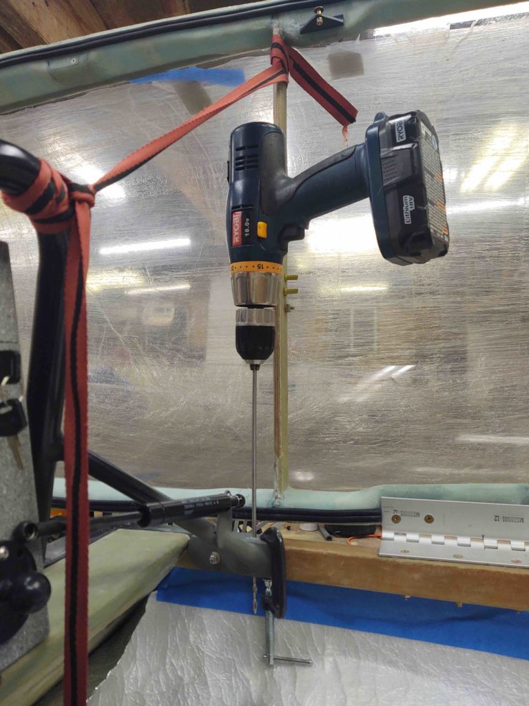
After securing the canopy with a tie down strap so I could get access behind the gas strut, I then drilled a #10 hole down vertically into the longeron, through the top plate of the rollbar attach rail.

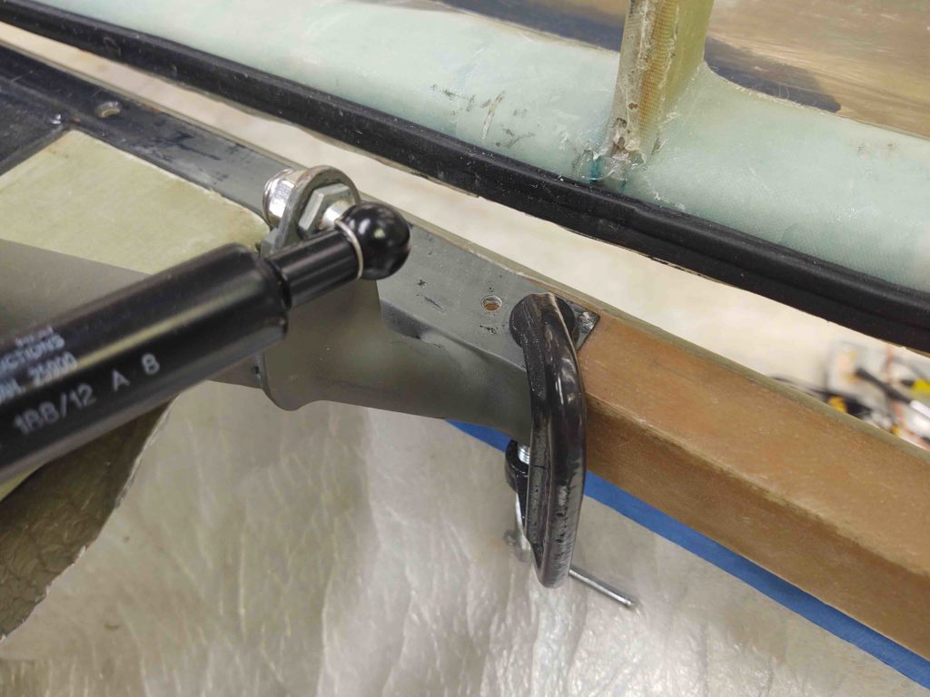
Here we have the resulting #10 hole . . .

After which, I countersunk the hole.

And then test-fitted the screw.

Here you can see a good amount of the screw poking out below the longeron.

Since I didn’t have my epoxy station operational just yet, along with wanting to mix up flox for multiple component installs, I stopped at this point and moved on to working on the wheel pants, organizing the shop more, and spending another good 45 minutes cleaning dead tape and bondo off the fuselage.

In part of my cleaning spree, I started working on the inside of the plane as well, starting with the nose.

I figured I should remove the small nose gear back-up battery and charge it…. well, a frozen button-head screw retaining the battery bracket had other ideas about that.

I even hit it with PB Blaster a couple of times and let it soak for about 30 minutes, then tried my cordless impact drill to remove it. This resulted in nothing more than a now stripped button head screw (they suck BTW!), so I hit it again with PB Blaster and let it soak overnight.

I’m hoping tomorrow I’ll spend more time working and less time hunting for stuff!

Chapter 9 – Wheel Pants

Today I started off early by getting my FAA Class III flight physical completed… another 2-year ticket to fly.

I then remounted the wheel pants using clecos in the alignment/hardware holes.

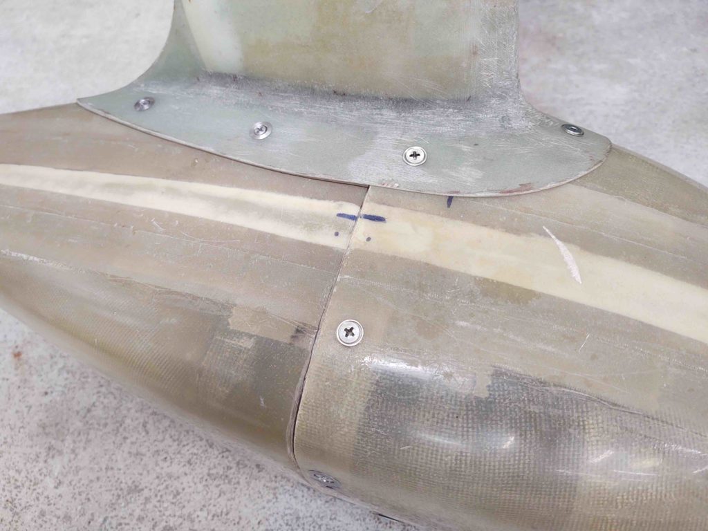
Thankfully everything went back together fairly smoothly. I would say that the skirt (wheel pant flange) on the gear seems to be pulling the aft end of each pant up about 1/8″, but beyond some minor requirements for trimming the interfaces, all looks pretty good!

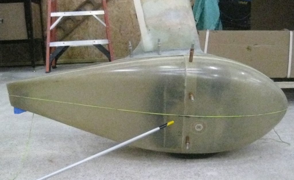
Although not exact or scientific, after a bit of fanagaling I ran a string from the front center point to the aft center point… I could manipulate the string up or down, but it did naturally rest on the midpoint centerline when I initially pulled the string tight. Close enough for me . . .

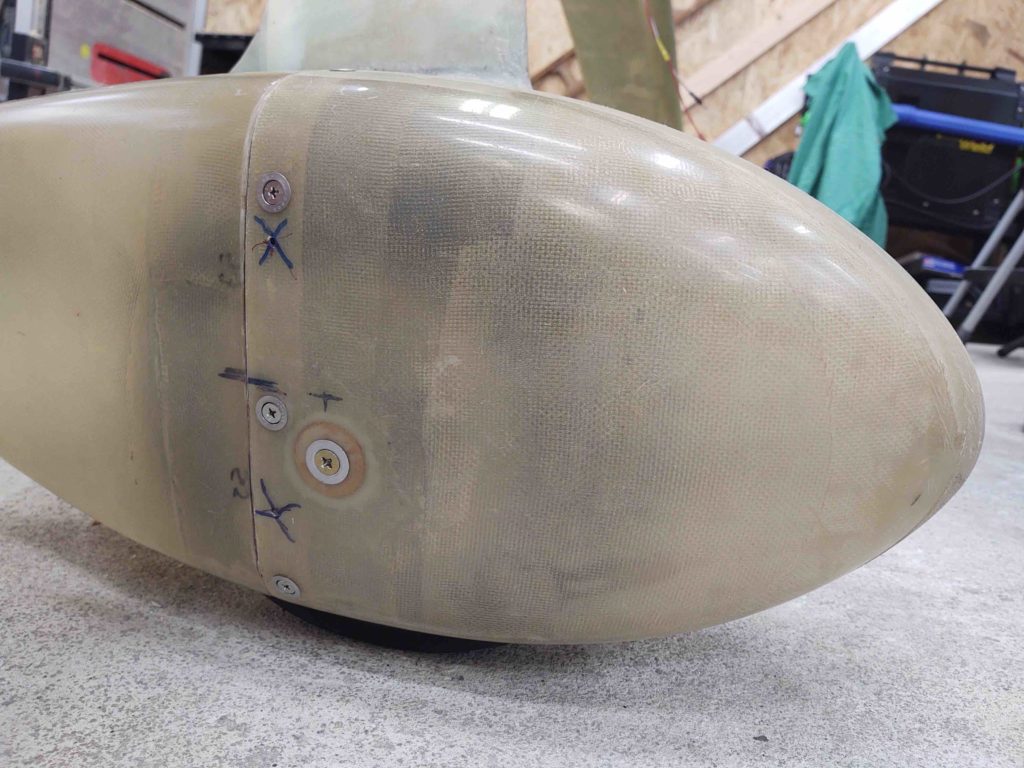
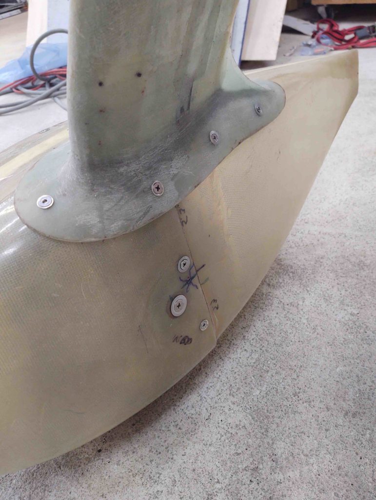
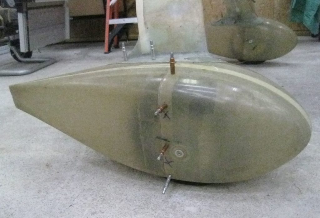
I then spent a good bit of time re-spacing and re-drilling the screw/CAMLOC positions. The net result is the addition of one screw/CAMLOC on each side.

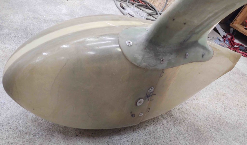
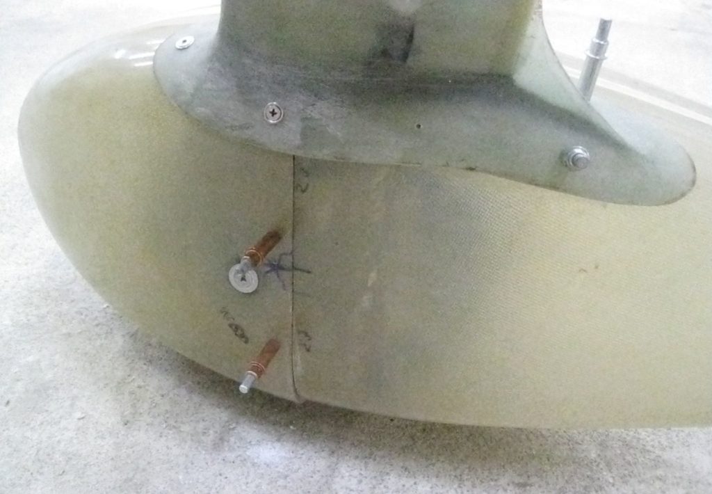
Note the X’s on the outboard (2x above) and inboard (1x below) where the old attach points were located.

There are some minor fit and finish issues that I need to deal with [note gap at junction] and I’ll dial those in as I finalize the wheel pants install.

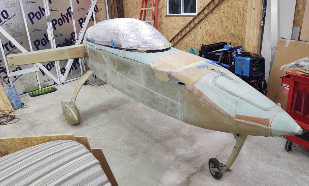
Here’s a shot of the fuselage –with the wheel pants installed– in its current state. Albeit its current state is a bit of mess, with quite a bit of duct tape pieces and residue adhered semi-permanently to the surfaces.

I’ll note I’ve been closing out each evening this week with a good 45-minute or so cleaning session to get all the tape residue removed. In addition, each night I’ve been working 1-2 bondo spots still remaining on the bottom aft corner of the CS spar from when I mounted the wings to the spar and drilled out the wing mounting bolts…. yes, the sins of the past! The good news is I’m close to having a clean slate (pun intended) on the external fuselage. Next will come some much needed internal fuselage cleanup.

The next step will be finalizing the actual wheel pant hardware install.

Chapter 18 – Turtledeck Check

As I get my “sea legs” underneath me, moving back into the realm of airplane building, I both want to get some low hanging fruit knocked out as I also assess my plan of action.

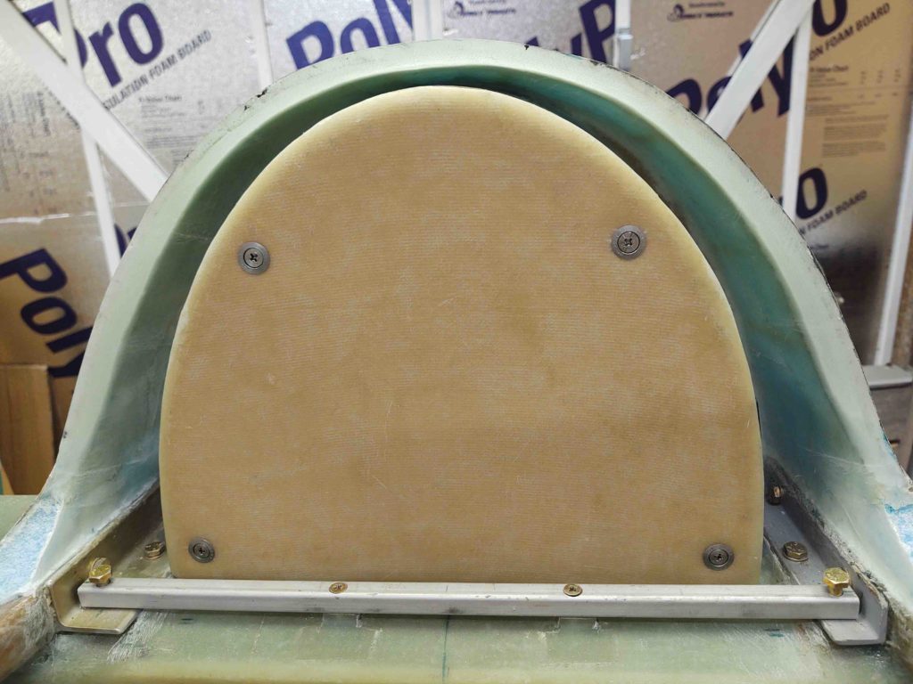
One thing I’ve really needed to do was to crack open the engine electrical components’ compartment (AKA: “GIB headrest”) to check for any corrosion from the many miles of road traveling this fuselage has done, and also its sitting inside non-temp controlled facilities during two different storms.

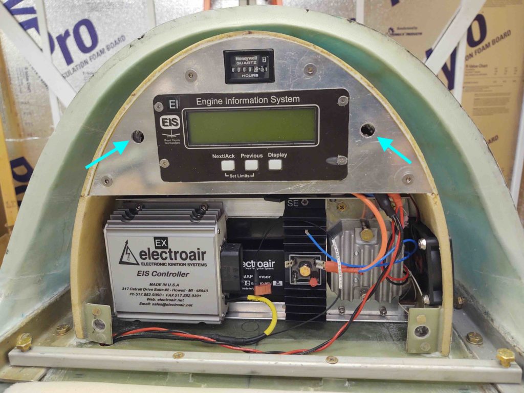
My #2 reason for cracking open the GIB headrest compartment is that you’ll note it is supposed to be attached in place by 4 CAMLOCs…. the upper 2 being MIA. That was simply because I had all 4 of the same length, but the top two needed to be just a tad longer. I had them on hand before I moved, but . . .

… the upper faceplate through-holes were too small {blue arrows}. I finally got around to using the Dremel Tool with a small sanding drum to widen each hole by about 0.050-0.070″ in diameter, at which point the CAMLOCs fit through and into their respective receptacles nicely.

Also note: although there was a bit of dust inside the compartment looked nice and clean with no noticeable corrosion anywhere.

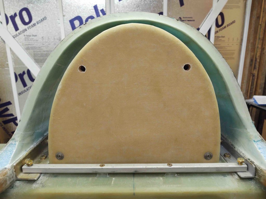
And here we have the upper CAMLOCs in place, making the GIB headrest compartment plate attachment official ….

Task complete . . . moving on!

Shop walls complete!

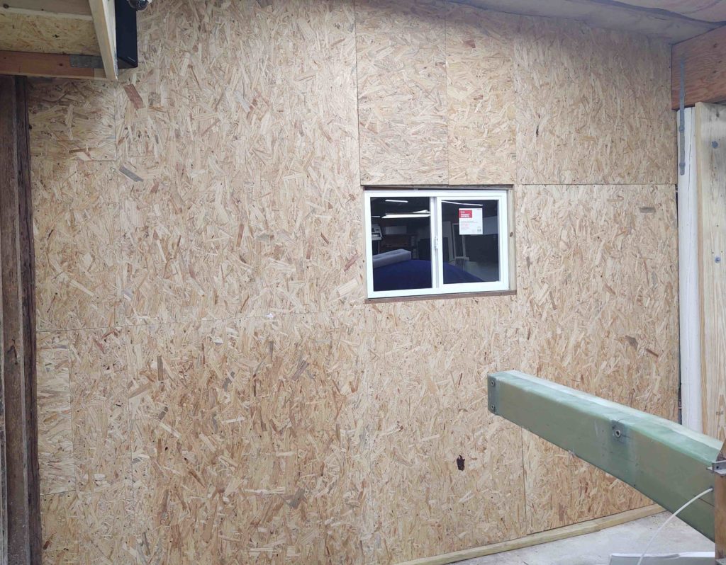
Over the last couple of days I was able to finish insulating and paneling the last segment of wall in the workshop.

Yes, I’m glad it’s over and I can now move on to bigger and better things, including getting back to work on the airplane!

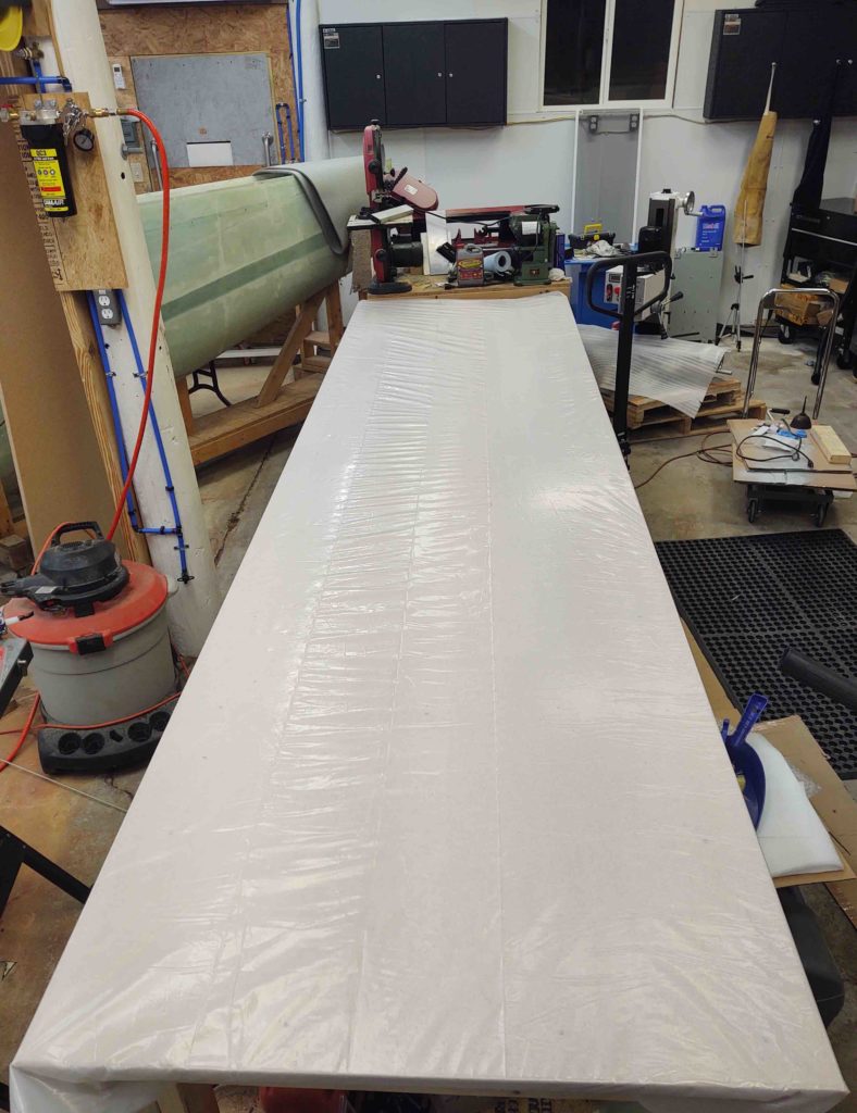
In addition to finishing the workshop walls, I finally got around to clearing off the workbench and getting it appropriately covered with plastic to protect it. A seemingly minor task that of course took nearly an hour to complete . . .

And with that, onward and upwards!

Workshop – Last window!

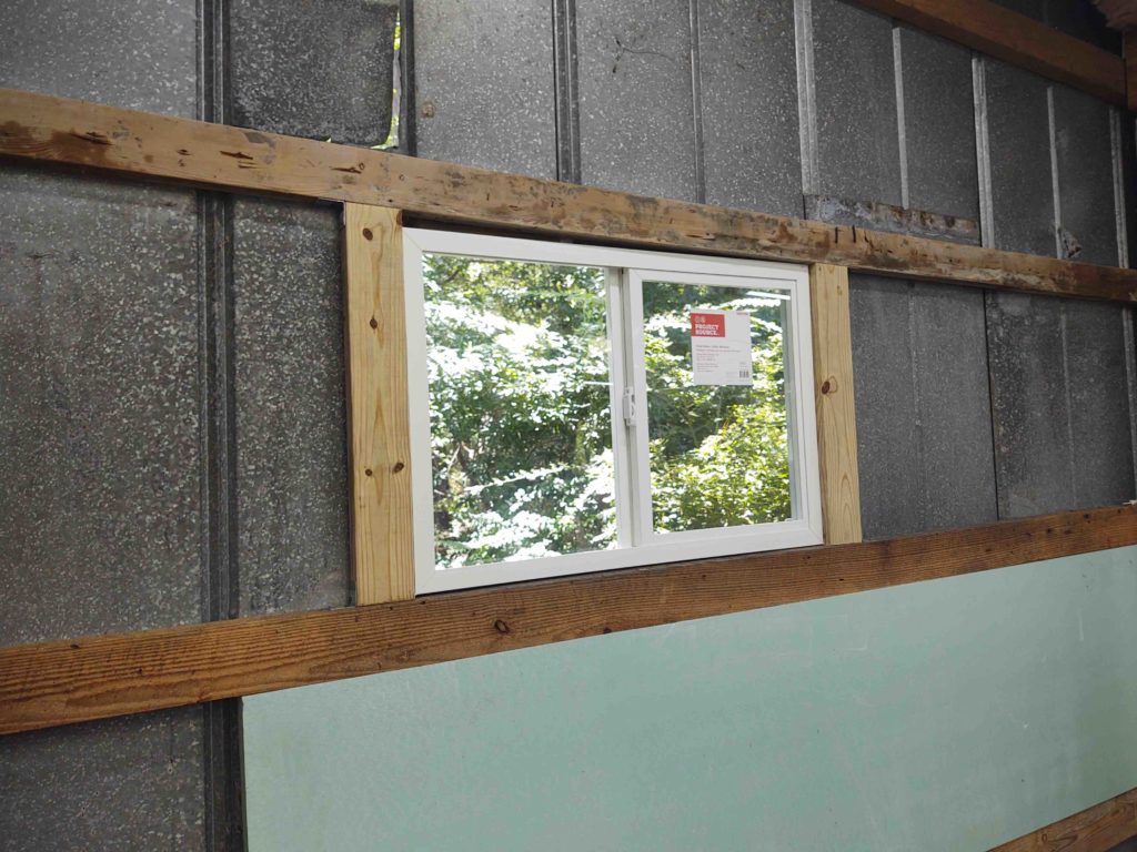
Today I got busy on installing the last window in the workshop. I would say “replace” but this is more of a new window install… replacing a semi-permanent patch of I’m guessing some type of past window.

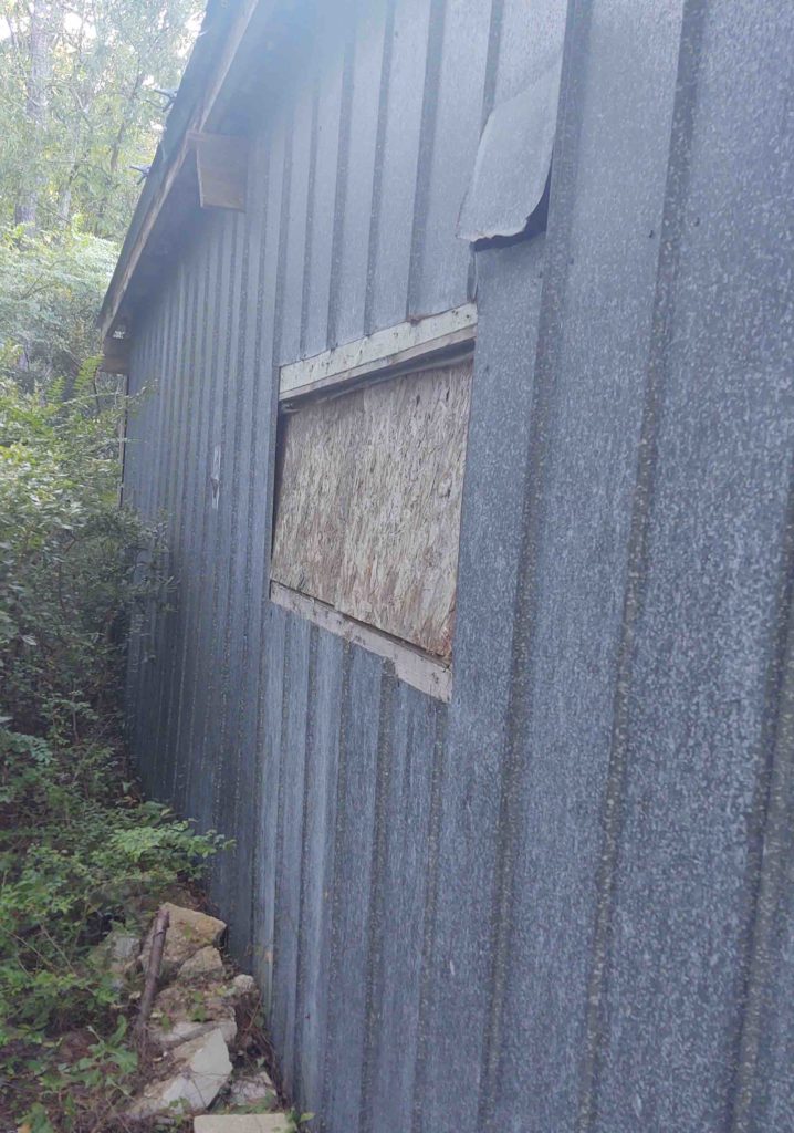
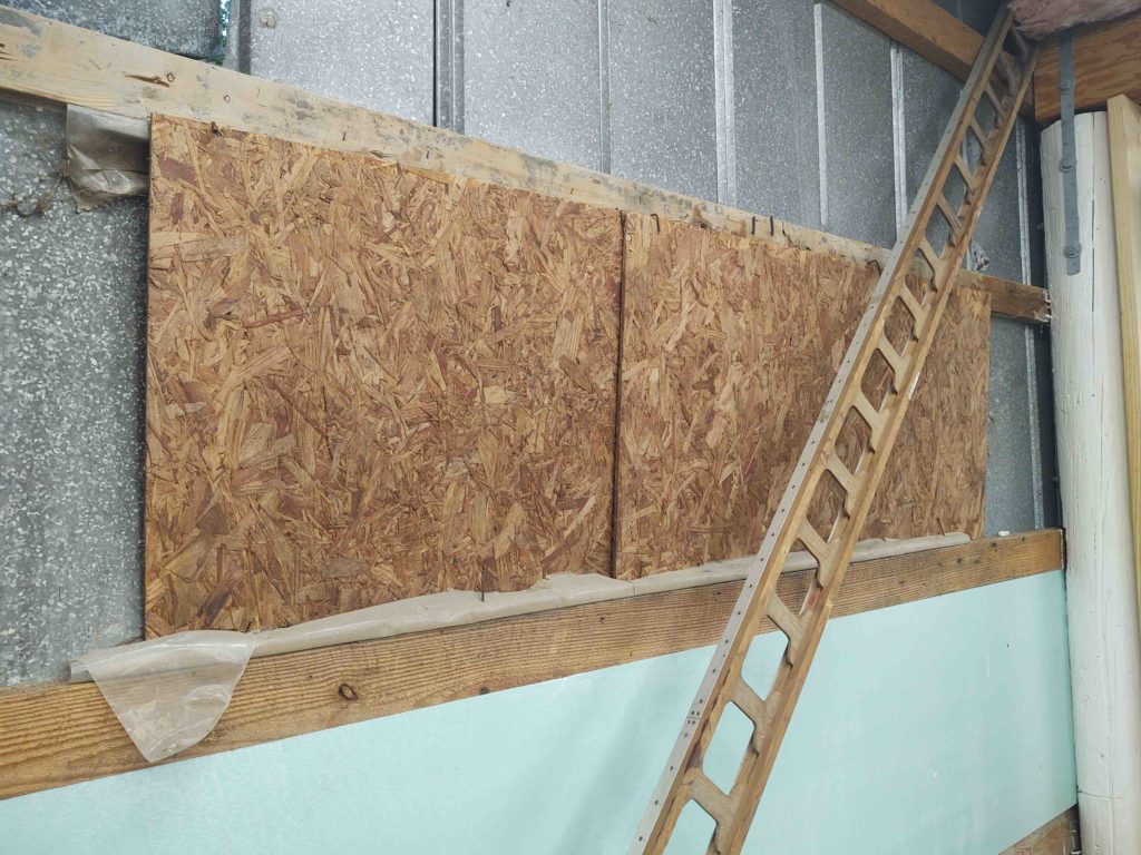
As you can see below, the window-shaped opening at the left end of the workshop was plugged with 2 pieces of OSB flooring paneling.

This is the view from the inside.

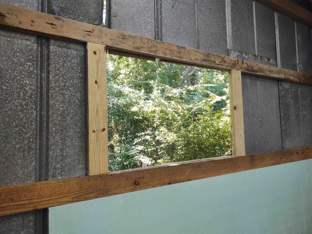
And after I removed the OSB panels, patched in the far end of the opening with a piece of metal siding and then framed in the window opening.

As with the other windows, to allow for mounting a flat-framed window to the ridged metal siding, I needed to create a frame around the opening.

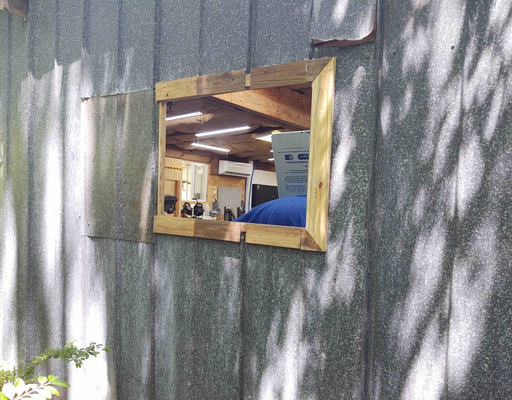
Here’s the last workshop window mounted (finally!)

Of course the next step is to finish insulating this segment of wall and then covering it with OSB paneling.

Workshop – Rain is back

I wasn’t going to post anything about my mundane shop actions over this last week, but since the rain has started back up I thought I would submit a report.

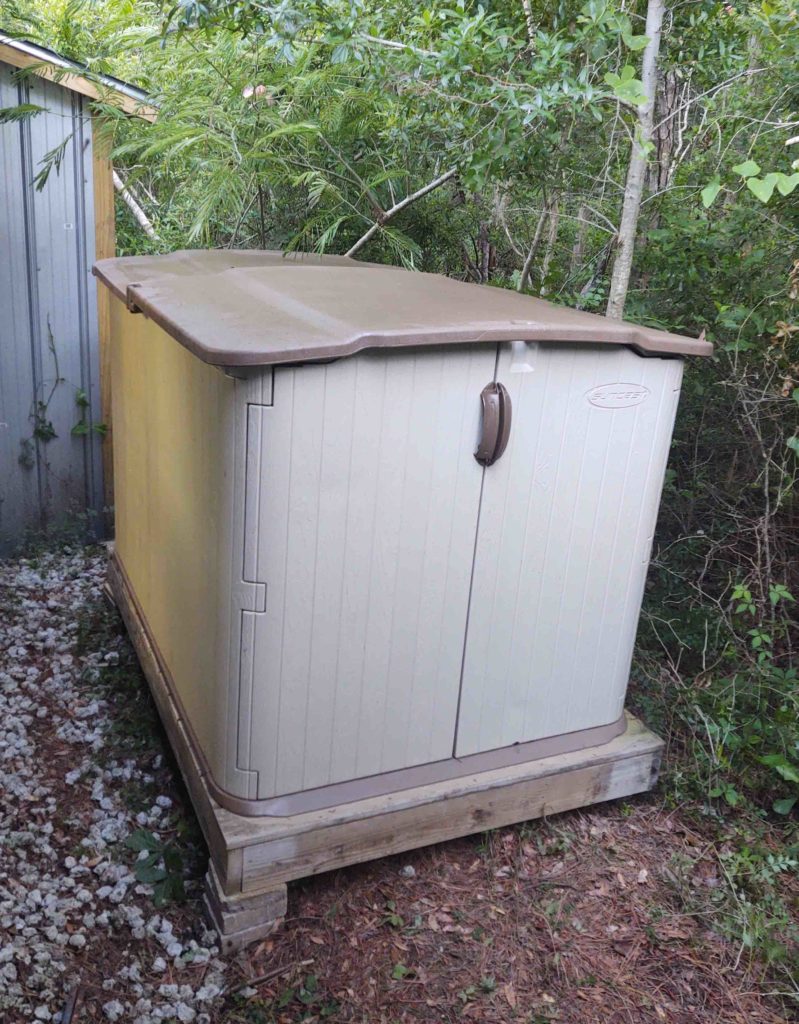
When I moved down here to NC from northern Virginia, I brought with me the base I built for a rather decent sized “Rubbermaid” storage shed. Incidentally, at my previous house this was about the largest sized shed I was “authorized” from the Home Owner’s Association –who have more authority up there than any entity on this planet. Thankfully, common sense and self-determination are more of the rule down here and keep BS Big Brother watchdogs out of one’s hair . . . but I digress.

In a string of prerequisite tasks to get the excess pile of 2x4s out of the front corner of my shop, and thus allow me room to get to work on the last segment of wall, I decided to do a bit of work on the area in and around the carport overhang (situated at the right end of the workshop).

Moreover, to get the area cleaned up and organized for yet even more stuff to be jammed underneath, I decided to re-assemble my shed in a location on the back side of the shop, which was essentially free, unused space previously.

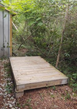
Thus, I cleared out some brush and then set up the (quite heavy) platform. I then leveled it.

Besides merely assembling the shed, I also cleaned off the months’ worth of spiders, webs, leaves and dirt from the respective panels.

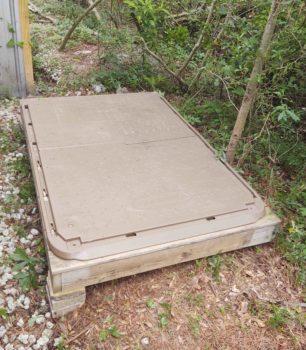
Here I’ve set the shed floor panels into place and secured them together.

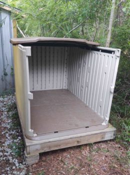
The walls and slide-opening top came next.

And finally the doors . . . and Voila! More storage to help un-encumber the carport area.

After the shed above was assembled (I still have to mount the front ramp back into place on the frame of the wood foundational base) I then uncrated and put the wheels on a decent-sized roll-around shop tool chest that I bought for the hangar. It has been sitting under my carport since early October taking up space and unused. After assembling (ie getting it out the way) I put it in my now somewhat organized garage.

I had big plans for finalizing the organization of the carport to allow all the unrequired stuff to come out of the workshop when the rain started back up. It’s been a bit sporadic, but definitely enough episodes and volume to have really gummed up any more serious work on the shop over the last number of days.

That being said, in the next day or so I plan on throwing myself wholeheartedly into getting the milling machine installed and online. If there are periods of no rain, I will also focus on getting the stack of 2x4s stored under the carport and start back in on completing the final segment of the workshop wall.